Case Study of Building Service in Public buildings
100
-
Upload
chong-chin-pin -
Category
Education
-
view
149 -
download
4
Transcript of Case Study of Building Service in Public buildings


1
Introduction to Building
1.1. Building History
1.2. Building Floor Plans
3~4
5
6
2
Fire Protection System (Active & Passive)
2.1. Introduction
2.2. Report Review
2.3. Case Study
2.4. Conclusion
7
8
9~10
11~29
30~32
3
Air Conditioning System
3.1. Introduction
3.2. Report Review
3.3. Case Study
3.4. Conclusion
33
34
35~37
38~54
55
4
Mechanical Ventilation System
4.1. Introduction
4.2. Report Review
4.3. Case Study
4.4. Conclusion
56
57
58~61
62~74
75~76
5
Mechanical Transportation System
5.1. Introduction
5.2. Report Review
5.3. Case Study
5.4. Conclusion
77
78
78~81
82~91
92
6 Summary / Conclusion93~96
7 References 97~100
CONTENT

1
INTRODUCTIONBUILDING HISTORY | BUILDING FLOOR PLANS
by
TAN JINGWEI
LIEW MIN YEE

1. INTRODUCTION
1.1. Building History
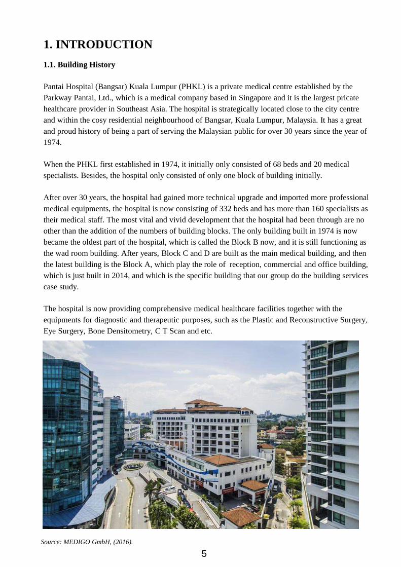
Pantai Hospital (Bangsar) Kuala Lumpur (PHKL) is a private medical centre established by the
Parkway Pantai, Ltd., which is a medical company based in Singapore and it is the largest pricate
healthcare provider in Southeast Asia. The hospital is strategically located close to the city centre
and within the cosy residential neighbourhood of Bangsar, Kuala Lumpur, Malaysia. It has a great
and proud history of being a part of serving the Malaysian public for over 30 years since the year of
1974.
When the PHKL first established in 1974, it initially only consisted of 68 beds and 20 medical
specialists. Besides, the hospital only consisted of only one block of building initially.
After over 30 years, the hospital had gained more technical upgrade and imported more professional
medical equipments, the hospital is now consisting of 332 beds and has more than 160 specialists as
their medical staff. The most vital and vivid development that the hospital had been through are no
other than the addition of the numbers of building blocks. The only building built in 1974 is now
became the oldest part of the hospital, which is called the Block B now, and it is still functioning as
the wad room building. After years, Block C and D are built as the main medical building, and then
the latest building is the Block A, which play the role of reception, commercial and office building,
which is just built in 2014, and which is the specific building that our group do the building services
case study.
The hospital is now providing comprehensive medical healthcare facilities together with the
equipments for diagnostic and therapeutic purposes, such as the Plastic and Reconstructive Surgery,
Eye Surgery, Bone Densitometry, C T Scan and etc.
Source: MEDIGO GmbH, (2016).
5

1. INTRODUCTION
1.2. Building Floor Plans
Block A Ground Floor, Pantai Hospital Kuala Lumpur, Public area.
Pantai Hospital is build on a slope area beside residential area. The whole design of the building is
heading towards environmental friendly. As looking from the plan, the arrangement of the whole
building is facing inwards creating a central space between the buildings. In this project, we will be
looking into Block A, which is the newest building constructed in 2014. The usage of Block A is
mainly for Clinics and offices. Unlike the other blocks, it does not construct specific technology for
hospital. The ground floor is open to public use and the other floors are for shareholders and clinics
departments.
Source: PHKL, (2017).
Ground Floor Landscape & Building Plan, Pantai Hospital, 2014
6

2
FIRE PROTECTION
SYSTEMINTRODUCTION | REPORT REVIEW | CASE STUDY |
CONCLUSION
by
TEH CHIE YANG

2. FIRE PROTECTION SYSTEM
2.1 INTRODUCTION
Fire is a special kind of oxidation known as combustion. Combustion occurred when rapid
combination of a substance with oxygen, involving the production of light and heat.
Fire has a triangle of needs: fuel, oxygen and high temperature. Without any element between this
three, building fire will be extinguished.
As the fire needed the triangle to produce fire, is is also influence on building design. The building’s
structure act as the fuel. The designer controls the choice of structural and finish materials, but rarely
final contents. The temperatures achieved in fires are well beyond the ability of building cooling
system to control. Lastly, Oxygen may be denied to a fire partly due to the limitation of ventilation.
Hence, to properly extinguish the fires, we have to fulfilled 3 objectives:
- Cool the fuel below the ignition point.
- Remove the oxygen supply.
- Separate the fuel from the oxygen.
Fire protection is playing a very important role to prevent this kind of situation happens. Prevention
of the heavy damages can be achieved by installing mechanical fire protection systems in the
building. FIre protection has been splitted into 2 categories: Active and Passive. Active and passive
fire protection system should be intended to intended to join the proficient of in new offices and
redesign ventures.
8

2. FIRE PROTECTION SYSTEM
2.2 REPORT REVIEW
2.2.1 Active Fire Protection
Active Fire Protection (AFP) is a group of systems that require some amount of action or motion in
order to work efficiently in the event of a fire. Actions may be manually operated, like a fire
extinguisher or automatic, like a sprinkler, but either way they require some amount of action. AFP
includes fire/smoke alarm systems, sprinkler systems, and fire extinguishers as well as firefighters.
Fire/smoke alarm systems are used to detect whether there is fire and/or smoke in a building.
Sprinkler systems are used to help slow the growth of the fire. Fire extinguishers and firefighters are
used to help put out the fire altogether.
Fortunately, recent decades have seen considerable developments in the area of active fire
protection, with systems becoming more sensitive and equipped with state-of-the-art technology, to
ensure maximum efficiency. This, in turn, has resulted in the number of serious indoor fire-related
incidents across the western world decreasing over the years, providing a safer and more protected
environment for modern citizens to live, work and shop in.
Having gained a basic understanding of what constitutes active fire protection, it is important that
property managers and layman citizens alike be aware of some of the most common measures for
fire detection and prevention which can be considered to fit into the umbrella term ‘active fire
prevention.’
Following is the example of active fire protection:
Water based system
Non-water based system
Alarm and detection system and devices
Smoke alarm system
9

2. FIRE PROTECTION SYSTEM
2.2.2 Passive Fire Protection
Passive Fire Protection (PFP) is a group of systems that compartmentalize a building through the use
of fire-resistance rated walls/floors. Compartmentalizing your building into smaller sections helps to
slow or prevent the spread of fire/smoke from one room to the next. PFP helps to limit the amount of
damage done to a building and provides its occupants more time for evacuation. PFP includes
fire/smoke dampers, fire doors, and fire walls/floors. Dampers are used to prevent the spread of
fire/smoke throughout the building through its ductwork. Fire doors help to compartmentalize a
building. Firestopping helps to separate the building into compartments. Photoluminescent egress
path markers help light the way to safety.
Passive Fire Protection begins at the designing and concept stages of any construction. It is built into
the buildings that will ensure the protection of occupants even in the event of the failure of the active
protection. The requirement for passive fire protection are structured in Uniform Building By-Law
(UBBL) 1984.
Passive Fire Protection can be used to delay the speeds of combustion and smoke spreading and at
the same time protecting the escape routes in order to prolong the time for the people to escape.
Example of the passive fire protection that is shown in Pantai Hospital is fire wall, fire exit door,
emergency exit signage, fire emergency staircase and fire evacuation route.
10

2. FIRE PROTECTION SYSTEM
2.3 Case Study
2.3.1 Active Fire Protection
2.3.1.1 Fire Hose Reel System
Hose Reel are firefighting equipment for use for a first-aid measure for building occupants.
They should be located somewhere users that are least likely to be endangered by fire. Hose-
reel installations are only for first aid fire-fighting only, but it is a good enough to extinguish
the initial stage of the fire. The hose reel drums are located in specific location that are more
require to be secured in Pantai Hospital. It is in red colour as to meet requirement.
Hose reel Drum
‘
Diagram of the hose reel system
11
2. FIRE PROTECTION SYSTEM
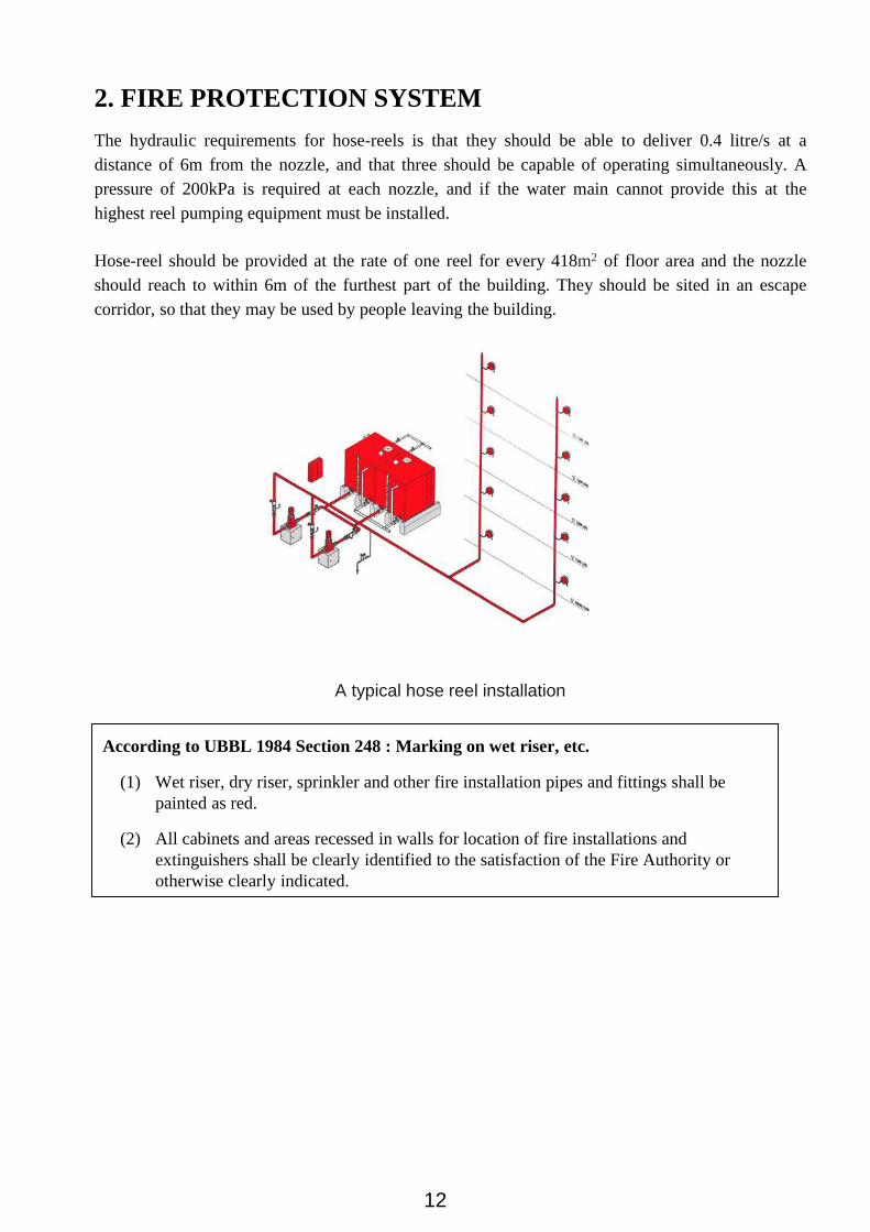
The hydraulic requirements for hose-reels is that they should be able to deliver 0.4 litre/s at a
distance of 6m from the nozzle, and that three should be capable of operating simultaneously. A
pressure of 200kPa is required at each nozzle, and if the water main cannot provide this at the
highest reel pumping equipment must be installed.
Hose-reel should be provided at the rate of one reel for every 418m2 of floor area and the nozzle
should reach to within 6m of the furthest part of the building. They should be sited in an escape
corridor, so that they may be used by people leaving the building.
A typical hose reel installation
According to UBBL 1984 Section 248 : Marking on wet riser, etc.
(1) Wet riser, dry riser, sprinkler and other fire installation pipes and fittings shall be
painted as red.
(2) All cabinets and areas recessed in walls for location of fire installations and
extinguishers shall be clearly identified to the satisfaction of the Fire Authority or
otherwise clearly indicated.
12

2. FIRE PROTECTION SYSTEM
2.3.1.2 Pump Controlling System
The pump controlling system in Pantai Hospital is used to supply water to the sprinklers and hose
reelss. Water pump is very important to fire protection system because it used diesel to operate
instead of electricity because electricity might not working during fire.
The water supply is distributed via several pipelines and each of the pipelines is supported by high
power pump so the water can move in high speed and immediately extinguish the fire.The fire pump
starts when the pressure in the fire sprinkler system drops below a threshold.
Pump Controlling System
A jockey pump is a pump connected to a fire sprinkler system and is intended to maintain pressure
in a fire protection piping system to an artificially high level so that the operation of a single fire
sprinkler will cause a pressure drop which will be sensed by the fire pump automatic controller,
causing the fire pump to start. The jockey pump is essentially a portion of the fire pump's control
system.
Jockey pump
13

2. FIRE PROTECTION SYSTEM
A duty pump will will pressurizes the water to maintain the system when the pressure pipe is not
functioning anymore. While standby pump is triggered when both duty pump and pressure pipe are
not working anymore. It will activated automatically. However, it can be switched off manually by
the nearby control panel.
Duty pump and standby pump
Control panel for duty pump and standby pump
According to UBBL 1984 Section 253 (2) : Emergency power system
Emergency power system shall be provided power for smoke control system, illumination,
fire alarm systems, fire pumps, public address systems, fire hits and other emergency system.
14

2. FIRE PROTECTION SYSTEM
2.3.1.3 Fire Alarm System
A fire alarm system serves primarily to protect life and secondarily to prevent property loss. Because
buildings vary in occupancy, flammability, type of construction, and value, a fire alarm system must
be tailored to the needs of a specific facility. One of the type of alarm system that is used in Pantai
Hospital is Manual-electrical alarm. Electrically operated alarms may be operated from break-
glass call points and, once operated, the alarms will continue to sound automatically. The usual
maximum travel distance to operate the alarm is 30m and the call points should be fitted at a height
of about 1.4m above the floor. The call point contains a depressed plunger pressing against a glass
front. When the glass is broken the plunger is released and operates the alarm system.
One of the many fire triggers in Pantai Hospital.
Break-glass call point Diagrammatic arrangement of system
15

2. FIRE PROTECTION SYSTEM
Another fire alarm system is applied by alarm bell. A fire alarm bell may use audible, visible, or
other stimuli to alert the occupants of a fire or other emergency condition requiring action. Audible
appliances have been in use longer than any other method of notification. The alarm bell produces
sound pressure levels between 45 and 120 decibels at ten feet. The signal can be triggered both
automatically or manually through manual call point or smoke detector.
Fire alarm bell
According to UBBL 1984 Section 155 : Fire mode of operation
(1) The fire mode mode of operation shall be initiated by a signal from the fire alarm
panel which may be activated automatically by one of the alarm devices in the
building or manually.
UBBL 1984 Section 237 : Fire Alarm
(1) Fire alarms shall be provided in accordance with the Tenth Schedule to these By-laws.
(2) All premises and building with gross floor area excluding car park and storage area
exceeding 9290 square metres or exceeding 30.5 metres in height shall be provided
with a two-stage alarm system with evacuation (continuous signal) to be given
immediately in the affected section of the premises while an alert (intermittent signal)
be given adjoining section.
(3) Provision shall be made for the general evacuation of the premises by action of a
master control.
16
2. FIRE PROTECTION SYSTEM
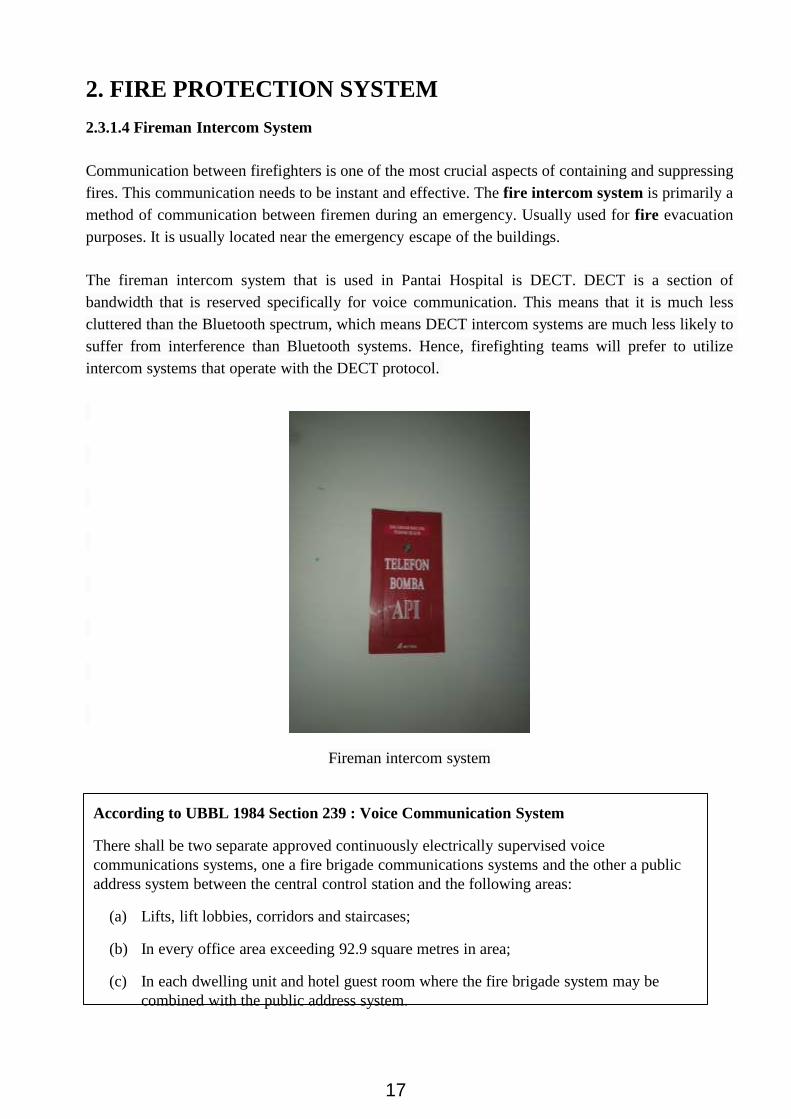
2.3.1.4 Fireman Intercom System
Communication between firefighters is one of the most crucial aspects of containing and suppressing
fires. This communication needs to be instant and effective. The fire intercom system is primarily a
method of communication between firemen during an emergency. Usually used for fire evacuation
purposes. It is usually located near the emergency escape of the buildings.
The fireman intercom system that is used in Pantai Hospital is DECT. DECT is a section of
bandwidth that is reserved specifically for voice communication. This means that it is much less
cluttered than the Bluetooth spectrum, which means DECT intercom systems are much less likely to
suffer from interference than Bluetooth systems. Hence, firefighting teams will prefer to utilize
intercom systems that operate with the DECT protocol.
Fireman intercom system
According to UBBL 1984 Section 239 : Voice Communication System
There shall be two separate approved continuously electrically supervised voice
communications systems, one a fire brigade communications systems and the other a public
address system between the central control station and the following areas:
(a) Lifts, lift lobbies, corridors and staircases;
(b) In every office area exceeding 92.9 square metres in area;
(c) In each dwelling unit and hotel guest room where the fire brigade system may be
combined with the public address system.
17

2. FIRE PROTECTION SYSTEM
2.3.1.5 Fire Extinguisher
Fire extinguishers are designed to tackle specific types of fire. There are six different classes of fire
and several different types of fire extinguishers. They are extremely valuable for extinguishing fires
at the early stages, but they cannot be used successfully to deal with large fires.
Pantai Hospital uses Portable fire extinguishers for their building. The term “portable fire
extinguishers’ generally covers first-aid fire fighting appliances which can be carried by hand from
which the extinguishing agent can be expelled, usually under pressure. There are 2 types of fire
extinguishers found in the building : Dry powder extinguishers and carbon dioxide extinguishers.
18

2. FIRE PROTECTION SYSTEM
a. Dry powder extinguisher
General-purpose dry powder is suitable for all classes of fire risks and is particularly suitable for
fires in flammable liquids. The powder consists of a finely divided, non-conducting, non-toxic,
water-repellent material which cools the flames,separates them from the burning material and
exclude oxygens. It also acts as a form of screen, thus enabling the operator to approach close the
fire. The dry powder stored in the body of the extinguisher is pressurised by nitrogen or air, which
expels the powder when the release valve is opened.
Alternatively, the dry powder may be expelled from the container by carbon dioxide gas after
breakage a seal of a cartridge.
Dry powder fire extinguisher Diagram of dry powder fire extinguisher
19

2. FIRE PROTECTION SYSTEM
b. Carbon dioxide fire extinguisher
Carbon dioxide is pressurised as a liquid inside a cylinder. Striking a knob at the top of the cylinder
pierces a disc to release the carbon dioxide which converts to a gas as it depressurises through the
extinguisher nozzle.
CO2 fire extinguisher Diagram of CO2 fire extinguisher
According to UBBL 1984 Section 227 : Portable extinguishers
Portable extinguisher shall be provided in accordance with relevant codes of practice and
shall be sited in prominent positions on exit routes to be visible from all directions and similar
extinguishers in a building shall be of the same method of operation.
20

2. FIRE PROTECTION SYSTEM
2.3.1.6 Sprinkler system
Water sprinklers provide an automatic spray dedicated to the area of fire outbreak. Each closed-head
sprinkler is held closed by either a heat-sensitive glass bulb or a two-part metal link held together
with fusible alloy.Sprinkler heads have temperature-sensitive elements that respond immediately to
heat, discharging the contents of the water main to which they are attached. It does less water
damage than fire hose due to it use less water to control a fire than the firefighting service. Therefore
it does preventing further damage from excess water.
Upright water sprinkler seen in Pantai Hospital
a. Upright Sprinkler
One of the water sprinklers that is used in Pantai Hospital is upright sprinklers. Upright sprinkler
heads project up into a space and have deflectors that spray the water downward. They are generally
used in mechanical rooms or other inaccessible areas to provide better coverage between
obstructions like beams or ducts. They also provide a circle spray pattern.
Diagram about upright water sprinkler Components of upright water sprinkler
21

2. FIRE PROTECTION SYSTEM
b. Recessed Pendent Sprinkler
Another type of sprinkler is recessed pendent sprinkler. It is different from upright sprinkler as it
shoots the water downward from the ceiling instead of upward. However, They are both shoot out
the water in a circle. As the recessed pendent sprinkler is built inside the ceiling, the pipes that
connecting the water will be hidden from our eyesight to avoid the unappealing appearance.
Recessed pendent sprinkler Diagram of the pendent sprinkler
According to UBBL 1984 Section 228 : Sprinklers valve
(1) Sprinkler valves shall be located in a safe and enclosed position on the exterior walls
and shall be readily accessible to the Fire Authority.
(2) All sprinkler systems shall be electricity connected to the nearest fire station to
provide immediate and automatic relay of the alarm when activated.
22
2. FIRE PROTECTION SYSTEM
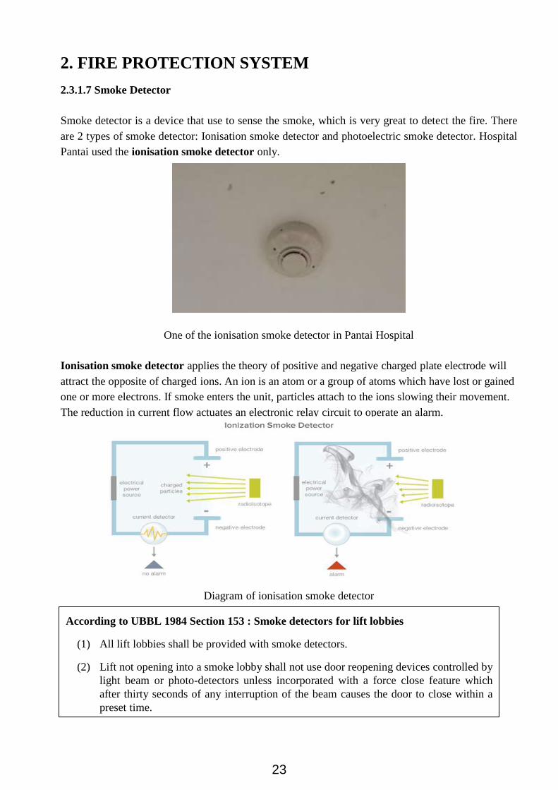
2.3.1.7 Smoke Detector
Smoke detector is a device that use to sense the smoke, which is very great to detect the fire. There
are 2 types of smoke detector: Ionisation smoke detector and photoelectric smoke detector. Hospital
Pantai used the ionisation smoke detector only.
One of the ionisation smoke detector in Pantai Hospital
Ionisation smoke detector applies the theory of positive and negative charged plate electrode will
attract the opposite of charged ions. An ion is an atom or a group of atoms which have lost or gained
one or more electrons. If smoke enters the unit, particles attach to the ions slowing their movement.
The reduction in current flow actuates an electronic relay circuit to operate an alarm.
Diagram of ionisation smoke detector
According to UBBL 1984 Section 153 : Smoke detectors for lift lobbies
(1) All lift lobbies shall be provided with smoke detectors.
(2) Lift not opening into a smoke lobby shall not use door reopening devices controlled by
light beam or photo-detectors unless incorporated with a force close feature which
after thirty seconds of any interruption of the beam causes the door to close within a
preset time.
23

2. FIRE PROTECTION SYSTEM
2.3.2 Passive Fire Protection
2.3.2.1 Fire Escape Plan
It is important to have a fire escape plan in a building as it provide a guidance for the people
when the fire is occurred. It is usually found beside the elevators. The fire escape plan shows
that it is important to know that people shouldn’t use the elevators during the fire happens.
The highlighted yellow shows the walkway to escape. The width of the walkway must be
wide enough for the people to escape .
Fire escape plan Assembly point
According to UBBL 1984 Section 169 : Exit Route
No exit route may reduce in width along its path of travel from the storey exit to the final exit.
According to UBBL 1984 Section 178 : Exist for institutional and other place of assembly
In buildings classified as institutional or places of assembly, exits to a street or large open
space, together with staircases, corridors and passages leading to to such exits shall be
located, separated or protected as to avoid any undue danger to the occupants of the place of
assembly from the fire originating in the other occupancy or smoke therefrom.
24

2. FIRE PROTECTION SYSTEM
2.3.2.2 Fire Switch
The fireman switch is a switch-disconnector/ isolator for special applications. They are designed to
be easy to spot and are used by firemen to turn off neon-lighting or other hazardous electrical
equipment in case of fire. The enclosure is made of nonflammable material. It is painted red in order
to be easy to spot. The on and off positions are clearly indicated on the front side with “I” and “O”.
The operating handle is designed in such a way that a fireman hook or axe can be used to switch off.
According to UBBL 1984 Section 240 : Electrical isolating switch
(1) Every floor or zone of any floor with a net area exceeding 929 square metres shall be
provided with an electrical isolation switch located within a staircase enclosure to
permit the disconnection of electrical power supply to the relevant floor or zone
served.
(2) The switch shall be of a type similar to the fireman’s switch specified in the Institution
of Electrical Engineers Regulations then in force.
25

2. FIRE PROTECTION SYSTEM
2.3.2.3 Fire Door
Fire doors have two main functions when fire breaks out. It is used to contain fire and smoke and
allow easy escape from the building. It is a specially made door with a fire-resistance rating. It can
reduce the spread of fire and smoke between separate compartments of a structure. Fire doors can be
seen in Pantai Hospital that near the to exit route as it is reasonably be built at there.
Fire door at one of the exits
According to UBBL 1984 Section 162 : Fire doors in compartment walls and separating
walls
(1) Fire doors of the appropriate FRP shall be provided.
(2) Openings in compartment walls and separating walls shall be protected by a fire door
having a FRP in accordance with the requirements for that wall specified in the Ninth
Schedule to these By-laws.
(3) Openings in protecting structures shall be protected by fire doors having FRP of not
less than half of requirement for the surrounding wall specified in the Ninth Schedule
to these By-laws but in no case less than half hour.
(4) Opening in partitions enclosing a protected corridor or lobby shall be protected by fire
doors having FRP of half-hour.
(5) Fire doors including frames shall be constructed to a specification which can be shown
to meet the requirements for the relevant FRP when tested in accordance with section
3 of BS476:1951.
26

2. FIRE PROTECTION SYSTEM
2.3.2.4 Fire Staircase
Fire staircase is the most common element in the escape route. It is basically connected together
with the fire door at every level. Pantai Hospital using the U-shaped staircase as the fire staircase
with material of concrete. There should be no obstacle in any staircase from the highest level to the
lowest level. Furthermore, the staircase should be wide enough for people to run through.
Fire staircase
According to UBBL 1984 Section 168 : Staircases
(1) Except as provided for in law 194 every upper floor shall have means of egress via at
least 2 separate staircase.
(2) Staircase shall be of such width that in event of any one staircase not being available
for escape purposes the remaining staircases shall accommodate the highest
occupancy load of any one floor discharging into it calculated in accordance with
provisions in the Seventh schedule to these By-laws.
(3) The required width of a staircase shall be the clear width between walls but handrails
may be permitted to encroach on this width to a maximum of 75 millimetres.
(4) The required width of a staircase shall be maintained throughout the length including
landings.
(5) Doors giving access to staircases shall be so positioned that their swing shall at no
point encroach on the required width of the staircase or landing.27

2. FIRE PROTECTION SYSTEM
2.3.2.5 Emergency Exit Signage
Emergency exit signage provides clear visual guidance to the nearest exit, which could prove
invaluable in an emergency. The exit signs are indicated with the neon green colour as it easily be
noticeable during dark. These signs are always lit up at night and remain light off during morning in
Pantai Hospital.
Emergency exit signage
According to UBBL 1984 Section 172: Emergency exit signs
(1) Storey exits and access such exits shall be marked by readily visible signs and shall
not be obscured by any decorations, furnishings or other equipment.
(2) A sign reading “KELUAR” with an arrow indicating the direction shall be placed in
every location where the direction travel to reach the nearest exit is not immediately
apparent.
(3) Every exit sign shall have the word “KELUAR” in plainly legible letter not less than
150 millimetres high with the principal strokes of the letters not less than 18
millimetres wide. The lettering shall be in red against a black background.
(4) All exit signs shall be illuminated continuously during periods of occupancy.
(5) Illuminated signs shall be provided with two electric lamps of not less than fifteen
watts each.
28

2. FIRE PROTECTION SYSTEM
2.3.2.6 Emergency Light
Emergency lighting is one component of the means-of-egress illumination and is part of a building’s
life safety systems. Emergency lighting can be described as any approved illuminating device and
appurtenance designed to automatically turn on when the primary power goes out. Exit signs are
used in combination with emergency lighting to provide means of egress lighting.
Emergency light
29
2. FIRE PROTECTION SYSTEM
2.4 Conclusion
In conclusion, fire protection is necessary in every building. Pantai Hospital has successfully
fulfilled the requirements about fire protection. As the building is relatively new, every fire
protection equipments are in a good condition. They have consider many aspects before they design
the layout of the building especially for the active fire protection system.
Design for active fire protection system is pretty hard compared to the passive fire protection as you
have to consider much when you are trying to place in certain area. Active fire protection provides a
very good way to control and extinguish fire, either automatically or manually. All active fire
protection systems are required to be installed and maintained in accordance with strict guidelines in
order to maintain compliance with the local building code and the fire code.
However, passive fire protection system is equally important to active fire protection system. Their
main function is to slow the spread and contain the fire as well as educating the occupants and
operators of the facility, ship or structure concerning operation and maintenance of fire-related
systems for correct function, and emergency procedures including notification for fire service
response and emergency evacuation. In Pantai Hospital, they have successfully provide a complete
passive fire protection system which can be very useful if the fire occurred.
To summarize the fire protection system, it is important in mitigating the unwanted effects of
potentially destructive fires. If a building doesn’t have a proper fire protection system, it will be a
large issue when the fire is actually happened. Pantai Hospital attaches great importance to fire
protection system which is very good as they care about the safety of the patients, visitors and
workers.
The Pantai Hospital has achieved the following requirements and regulations:
According to UBBL 1984 Section 248 : Marking on wet riser, etc. Wet riser, dry riser, sprinkler
and other fire installation pipes and fittings shall be painted as red. All cabinets and areas
recessed in walls for location of fire installations and extinguishers shall be clearly identified
to the satisfaction of the Fire Authority or otherwise clearly indicated.
According to UBBL 1984 Section 253 (2) : Emergency power system, emergency power system
shall be provided power for smoke control system, illumination, fire alarm systems, fire
pumps, public address systems, fire hits and other emergency system.
According to UBBL 1984 Section 155 : Fire mode of operation, the fire mode mode of operation
shall be initiated by a signal from the fire alarm panel which may be activated automatically
by one of the alarm devices in the building or manually.
30

2. FIRE PROTECTION SYSTEM
2.4 Conclusion
UBBL 1984 Section 237 : Fire Alarm, fire alarms shall be provided in accordance with the Tenth
Schedule to these By-laws. All premises and building with gross floor area excluding car
park and storage area exceeding 9290 square metres or exceeding 30.5 metres in height shall
be provided with a two-stage alarm system with evacuation (continuous signal) to be given
immediately in the affected section of the premises while an alert (intermittent signal) be
given adjoining section. Provision shall be made for the general evacuation of the premises
by action of a master control.
According to UBBL 1984 Section 239 : Voice Communication System, there shall be two
separate approved continuously electrically supervised voice communications systems, one a
fire brigade communications systems and the other a public address system between the
central control station and the following areas:
a. Lifts, lift lobbies, corridors and staircases;
b. In every office area exceeding 92.9 square metres in area;
c. In each dwelling unit and hotel guest room where the fire brigade
system may be combined with the public address system.
According to UBBL 1984 Section 227 : Portable extinguishers, portable extinguisher shall be
provided in accordance with relevant codes of practice and shall be sited in prominent
positions on exit routes to be visible from all directions and similar extinguishers in a
building shall be of the same method of operation.
According to UBBL 1984 Section 228 : Sprinklers valve, sprinkler valves shall be located in a
safe and enclosed position on the exterior walls and shall be readily accessible to the Fire
Authority. All sprinkler systems shall be electricity connected to the nearest fire station to
provide immediate and automatic relay of the alarm when activated.
According to UBBL 1984 Section 153 : Smoke detectors for lift lobbies All lift lobbies shall be
provided with smoke detectors. Lift not opening into a smoke lobby shall not use door
reopening devices controlled by light beam or photo-detectors unless incorporated with a
force close feature which after thirty seconds of any interruption of the beam causes the door
to close within a preset time.
According to UBBL 1984 Section 169 : Exit Route, no exit route may reduce in width along its
path of travel from the storey exit to the final exit.
According to UBBL 1984 Section 178 : Exist for institutional and other place of assembly, in
buildings classified as institutional or places of assembly, exits to a street or large open
space, together with staircases, corridors and passages leading to to such exits shall be
located, separated or protected as to avoid any undue danger to the occupants of the place of
assembly from the fire originating in the other occupancy or smoke therefrom.31

2. FIRE PROTECTION SYSTEM
2.4 Conclusion
According to UBBL 1984 Section 240 : Electrical isolating switch, every floor or zone of any
floor with a net area exceeding 929 square metres shall be provided with an electrical
isolation switch located within a staircase enclosure to permit the disconnection of electrical
power supply to the relevant floor or zone served. The switch shall be of a type similar to the
fireman’s switch specified in the Institution of Electrical Engineers Regulations then in
force.
According to UBBL 1984 Section 162 : Fire doors in compartment walls and separating walls,
fire doors of the appropriate FRP shall be provided. Openings in compartment walls and
separating walls shall be protected by a fire door having a FRP in accordance with the
requirements for that wall specified in the Ninth Schedule to these By-laws. Openings in
protecting structures shall be protected by fire doors having FRP of not less than half of
requirement for the surrounding wall specified in the Ninth Schedule to these By-laws but in
no case less than half hour. Opening in partitions enclosing a protected corridor or lobby
shall be protected by fire doors having FRP of half-hour. Fire doors including frames shall be
constructed to a specification which can be shown to meet the requirements for the relevant
FRP when tested in accordance with section 3 of BS476:1951.
According to UBBL 1984 Section 168 : Staircases, except as provided for in law 194 every upper
floor shall have means of egress via at least 2 separate staircase. Staircase shall be of such
width that in event of any one staircase not being available for escape purposes the remaining
staircases shall accommodate the highest occupancy load of any one floor discharging into it
calculated in accordance with provisions in the Seventh schedule to these By-laws. The
required width of a staircase shall be the clear width between walls but handrails may be
permitted to encroach on this width to a maximum of 75 millimetres. The required width of a
staircase shall be maintained throughout the length including landings. Doors giving access
to staircases shall be so positioned that their swing shall at no point encroach on the required
width of the staircase or landing.
According to UBBL 1984 Section 172: Emergency exit signs, storey exits and access such exits
shall be marked by readily visible signs and shall not be obscured by any decorations,
furnishings or other equipment. A sign reading “KELUAR” with an arrow indicating the
direction shall be placed in every location where the direction travel to reach the nearest exit
is not immediately apparent. Every exit sign shall have the word “KELUAR” in plainly
legible letter not less than 150 millimetres high with the principal strokes of the letters not
less than 18 millimetres wide. The lettering shall be in red against a black background. All
exit signs shall be illuminated continuously during periods of occupancy. Illuminated signs
shall be provided with two electric lamps of not less than fifteen watts each.
32

3
AIR CONDITIONING
SYSTEMINTRODUCTION | REPORT REVIEW | CASE STUDY |
CONCLUSION
by
CHONG CHIN PIN
LIEW MIN YEE

3. AIR CONDITIONING SYSTEM
3.1 Introduction
Air conditioning system is composed of a group of components and arrange in sequence to
perform many functions simultaneously. It controls and maintains the temperature, humidity, air
movement, air cleanliness, sound level, and pressure differential in a space to maintain the
occupants' thermal comfort. The purpose of installing air conditioning system to a building is to keep
the indoor space comfort level higher than the outdoor. Comfort Requirements that are typically
impacted by the air conditioning system are Dry-bulb temperature, humidity, cleanliness of air and
noise levels.
3.1.1 Refrigeration Cycle
Refrigeration Cycle. Pete Hoffman, (2006).
For the economic purpose, the refrigerant will be used repeatedly. The refrigerant is used to
remove the heat from one area to cool this area and to expel this heat in another area.
Refer to the Refrigeration cycle diagram above:
1. The refrigerant comes into the compressor as a low-pressure gas. The gas has been
compressed and then moves out of the compressor as a high-pressure gas.
2. The gas then flows to the condenser. It condenses to a liquid and releases its heat to the
outside air.
3. The liquid then moves to the expansion valve under high pressure. This valve restricts
the flow of the fluid and lowers its pressure.
4. The low-pressure liquid then moves to the evaporator, where heat from the inside air is
absorbed and changes it from a liquid to a gas.
5. The low-pressure liquid then moves to the evaporator. The heat from the inside air will
be absorb and change it from a liquid to a gas.
6. The refrigerant as a hot low-pressure gas moves back to the compressor. The entire cycle
repeats again.
A refrigeration cycle is a means of transferring heat source from high-temperature region to low-
temperature region to decrease its temperature. However, the reverse process cannot occur itself, it
needs to include the refrigerator. The four stages of the cycle includes compression, condensing,
expansion and vaporization at a constant pressure.
Principles of Refrigeration Cycle
● Liquids absorb heat when
changed from liquid to gas
● Gasses give off heat when
changed from gas to liquid.
34

3. AIR CONDITIONING SYSTEM
3.2 Report Review
There are different type of common air condition system in high-rise building, Centralised Air
Conditioning System, District Cooling System(DCS) and chilled beam system. The focal point in
this report will be in Malaysia, a tropical country which only only require cooling system.
3.2.1 Centralised Air Conditioning
Centralised Air Condition system can be use in both high-rise and low-rise building which spaces
that needs to be completely air conditioned. This system comprised by a huge compressor which
can produce high tons of chilled air. Along with refrigerator principle, AC contain three main parts:
condenser, evaporator and compressor.
The centralised air duct draw room’s air through return ducts, then transfers cool air through a filter
and follow by air-supply duct, chilled air is route to different rooms. However, it is not suitable to
cool down a big space such as auditorium. It is only feasible with a central conditioning unit. The
condenser and compressor are placed in an outdoor unit. The function of centralised air conditioning
does not create heat or cool air, it transfer the heat from undesirable area to a specific space through
a furnace.
3.2.2 District Cooling System
District Cooling System (DCS) is a system using water plant to distribute chilled water to multiple
buildings through underground insulated pipelines.This system can be apply to industrial and
residential buildings. This system only require one cooling plant to cool down multiple buildings in
one district by running water to lower down air temperature of a bigger building.
Centralised Air Conditioning used in residential Centralised Air Conditioning cycle plan
35

3.2.2 District Cooling System Cont’
3.2.3 Chilled Beam System
Chilled Beam System is one of the most common HVAC system designed to heat or cool high-rise
building, mainly for cooling building. There are two main types of chilled beams in this system :
active and passive. The main components of this system are copper tubing, bonded to aluminium
fins, tubes and water plant. Usually placed at ceiling level. This system are more quiet than the other
system and does not require mechanical room or large ductwork. However, this system works better
to building based on heating and cooling instead of ventilating.
3.2.3.1 Passive Chilled Beam(PCB)
A PCB works by leading chilled water through the tube and cool down the warm air that rises
towards the ceiling. After the warm air cooled down, it descends back to the room, creating
convection air motion to cool down space without using any fan. However, PCB require ventilation
air to be delivered by a separate furnace.
3.2.3.2 Active Chilled Beam(ACB)
The usage of ACB are more common than PCB due to the cooling efficiency. ACB contains an
integral air supply which induce air from space up through cooling coil. This process allow ACB to
provide much more cooling capacity.
3. AIR CONDITIONING SYSTEM
The components in District Cooling System(DCS) are more simple than other system for high-
rise. It requires a Central Chiller Plant, a distribution network and a user station. Central Chiller
Plant generate cooling water, then distribute the water through pipelines to user station.
District Cooling System is one of the newest system design that covered various consideration,
the system can be powered by electricity or natural gas. For liquid source it can use either sea
water,water or other media. It cuts down uses of electricity and maintenance costs dramatically.
Hence, it becomes one of the economical and environment friendly system in tropical country.
District Cooling System(DCS), Putrajaya, Malaysia Diagram of District Cooling System(DCS)
36

3.2.3.2 Active Chilled Beam(ACB) cont’
3. AIR CONDITIONING SYSTEM
Circulation of Chilled Beam SystemComparison of PCB and ACB
37

3.3 Case Study
3.3.1 Introduction
Pantai Hospital is located at tropical country, which ventilating and air-conditioning(VAC) are
only needed in the system. Consider the large cooling capacity, cost efficiency and environment
friendly of the building, Pantai Hospital is running with Chilled Water Central Air-Conditioning
System, commonly known as Chilled Water System.
3.3.2 Chilled Water System
A chilled-water air handler is located in an equipment room on each floor of the building.
Each air handler is equipped with a variable volume supply fan and discharges conditioned supply
air into ductwork located in the ceiling plenum above each floor. The supply ductwork is connected
to the variable-air-value system (VAV) terminal units that serve each zone. Air returns from the
zones through the open ceiling plenum into the equipment room, where it is drawn back into the air
handler. The chilled water is provided by a water-cooled chiller that is located in the basement,
along with the chilled water and condenser water pumps. A cooling tower is located on the roof.
For the Pantai Hospital, heating is provided by a hot-water boiler in the basement and hot-
water heating coils located at the discharge of each VAV terminal unit. Then, the system-level
controller ties the unit controllers on each of the VAV terminal units to the controllers on the air
handlers and also coordinates the operation of the chiller, the cooling tower, the pumps, the hot-
water boiler, and the central exhaust fan.
3. AIR CONDITIONING SYSTEM
38

3.3.2 Chilled Water System Cont
3.3.2.1 Centrifugal Water Chiller
Centrifugal water chillers can divide into two types which are water-cooled or air-cooled.
Pantai Hospital is using the water cooled centrifugal compressor package in sizes of 150 tons(350
kW) or more. These complete package chillers will include the compressor, condenser, evaporator,
internal piping and capacity controls. The centrifugal water chiller is located in the basement, a heat
remover using vapor-compression refrigeration cycle. The function is to cool down water that flows
through pipelines in the building and passes through the system and dehumidify the air in the
building. In Pantai Hospital, there is four chiller placed behind the pumps.
These particular centrifugal water chillers make use of a shell-and-tube evaporator.
The refrigerant absorbs heat from the water flowing through the tubes. A second shell-and-tube heat
exchanger serves as the water-cooled condenser, where the refrigerant is condensed inside the shell
and water flows inside tubes. The refrigerant is metered through the system using an expansion
device such as a fixed orifice plate. Economizer has used to enhance the efficiency of the chillers
with multiple compressor impellers.
3. AIR CONDITIONING SYSTEM
Chilled water system. Source: Convergence Training, (2016).
UBBL-SECTION 41
(3) The provisions of the Third Schedule to these By-laws apply to buildings which are
mechanically ventilated or air-conditioned.
39

3.3.2.1 Chilled Water System Cont
3. AIR CONDITIONING SYSTEM
Diagram of water chiller, Pantai Hospital Chillers behind pumps, Pantai Hospital
Centrifugal Water Chiller, Pantai Hospital
MS 1525:2014
8.2.1 Air conditioning systems and equipment shall be sized to provide no more than the space and
system loads calculated in accordance with 8.1 above, consistent with available equipment
capacity. Redundancy in the capacity of equipment, if incorporated into the sizing of the duty
equipment, should include efficiency devices such as variable speed drive, high-efficiency motor,
efficient unloading devices, multi compressors etc. so as not to diminish the equipment/system
efficiency when operating at varying loads.
8.2.2 Where chillers are used and when the design load is greater than 1000 kWr, a minimum of
either two chillers or a single multi-compressor chiller should be provided to meet the required
load.
40

3.3.2.1.1 Water Chiller Components
1. Air Switch
2. Non-airborne Starting Cabinet
3. Motor Terminal Box
4. Oil Pump Control Box
5. Swith Box
6. Air Vent
7. Pressure Gauge
8. Cool Water Pump
9. Cooling Water Pump
10. Cooled Water Pump Starter
11. Cooling Water Pump Starter
12. Cooling Tower Starter
3. AIR CONDITIONING SYSTEM
Evaporator
Condenser
Pipelines and Connection Figure of Chilled Water System. Dunham-Bush, (n.d.).
1# Main Power Entering Starting Cabinet
2# From Switch Box to Cooling Tower
Starter
3# From Switch Box to Cooling Pump Starter
4# From Switch Box to Cooled Pump Starter
5# From Main Power to Oil Pump Control Box
6# From Starting Cabinet to Control Box
7# From Starting Cabinet to Main Motor
41

3.3.2.1.1 Water Chiller Components
Flooded Shell-and-Tube Evaporator
The flooded shell-and-tube evaporators are used in chiller systems of Pantai Hospital. The
evaporator consists of a shell which is a large pressure vessel with a large number of tubes
compressed and inserted in it. However, the shell is not filled entirely with tubes. This is to maintain
the refrigerant level below the top of the shell so that liquid droplets settle down due to gravity and
are not carried by the vapor leaving the shell. If the shell is completely filled with tubes, then a surge
drum is provided after the evaporator to collect the liquid refrigerant.
At this stage, heat is transferred from the relatively warm water to the refrigerant, causing the
liquid refrigerant to boil and resulting vapor. The refrigerant flows along the shell side to absorb heat
from the relatively warm water that flowing through the tube bundle. Then, fluid to be chilled flows
along the tube. It has passed through an eliminator to prevent liquid from being drawn upward. The
float valve which acts as float valve maintain the level of the refrigerant. In order to transfer heat
efficiently, a large heat transfer area should be used, leading to the use of many tubes. In this way,
waste heat can be put to use. This is an efficient way to conserve energy.
3. AIR CONDITIONING SYSTEM
Evaporator component section diagram
42

3.3.2.1.1 Water Chiller Components
Centrifugal Compressor
In the refrigeration cycle, the compressor is a pump which provides the work energy to move
the vaporized refrigerant from low-pressure region (evaporator) to high-pressure region
(compressor) through the system. It uses the principles of dynamic compression which involves
converting energy from one to another. This helps to increase the pressure and temperature of the
gaseous refrigerant from low pressure and cooled temperature to high-pressure and high-temperature
gas. Then, the refrigerant will be pumped to the condenser.
The type of the compressors in Pantai Hospital is the centrifugal compressor. This type of
compressors is normally used in large water chillers. It is low in sound level, low-cost and has great
reliability. Centrifugal compressors are generally available in prefabricated chillers from 100 to
3,000 tons [350 to 10,500 kW], and up to 8,500 tons [30,000 kW] as built-up machines.
√
3. AIR CONDITIONING SYSTEM
Centrifugal Compressor Section Diagram
Rotating impeller is the core component of the centrifugal compressor. The rotation of the
impeller increases the velocity and kinetic energy of the refrigerant vapor. Centrifugal compressors
use 1 or more impellers to increase the pressure of the refrigerant. After the accelerated refrigerant
vapor leaves the last impeller, it collects in the compressor volute and transfers to the condenser.
Part of the Centrifugal Compressor.
TRANE, 2012.
Multistage compressor. TRANE, 2012.
43

3.3.2.1.1 Water Chiller Components
Water-Cooled Condenser
A Water-Cooled Condenser is a heat exchanger that rejects the heat of refrigerant, it converts
gas to the liquid flowing through it.
After compress into high-pressure and hot temperature, the vaporized refrigerant is then
discharged from the compressor into the condenser. In the water-cooled condenser, water is pumped
through the tubes while refrigerant vapor fills the shell space surrounding the tube bundle to transfer
the refrigerant vapor to water. After the heat transfers from the hot, high-pressure refrigerant vapor
to the water, refrigerant condenses on the tube surfaces. There has a baffle inside the condenser
which helps distribute the refrigerant evenly. Then, the condensed liquid refrigerant will continue
flow through the expansion devices and economizer.
An economizer can be used in conjunction with multiple expansion devices to improve the
efficiency of a multi-stage chiller. Before entering the evaporator, the liquid refrigerant from the
condenser flows through the expansion device that reduces its pressure and temperature to
evaporator conditions.
3. AIR CONDITIONING SYSTEM
Water-Cooled Condenser Section Diagram
Economizer. TRANE, (1012).
44

Expansion Valve
Expansion Valve helps liquid refrigerant lower the pressure before flowing through the
evaporator which changes the state from liquid to gas. Additionally, the heat is not removed from the
valve, only the pressure has been lower down. At this time, the refrigerant is at its coolest when it
leaving the expansion valve to enter the evaporator.
3.3.2.2 Chilled Water Pump
The water pump is located in the basement along with the chiller. The pump set is to keep the
pressure in the chilled water network constant and to channel the chilled water from the chillers to
the cooling tower. All the pumps will be working based on the reading from the differential pressure
sensor placed between the header supply and return lines. When one pump is running at full speed
another pump will be turned on and its speed is increased so that the pressure difference setpoint is
achieved. The pumps are operated in a sequence, the pump that has been running the least should
become the pump that is turned on first, and so on.
3. AIR CONDITIONING SYSTEM
Expansion Valve Section Diagram
Chilled Water Pump, Pantai Hospital
45

3. AIR CONDITIONING SYSTEM
3.3.2.3 Variable-Air-Value System (VAV)
A variable-air-volume (VAV) system varies the quantity of constant- temperature supply air
in response to the changing cooling load in the space.
Each conditioned space, or zone ( a group of similar spaces) in Pantai Hospital has a separate
VAV terminal unit that delivered the different quantity of supply air to that space or zone. A
thermostat will compare the dry-bulb temperature in the conditioned space to a setpoint. It then
modulates the quantity of supply air needed to be delivered to space by changing the position of the
airflow modulation device in the VAV terminal unit to maintain a constant supply air temperature.
3.3.2.4 Air Handler
The central air handler for Pantai Hospital is installed in a dedicated mechanical room. The
return-air dampers draw the return air from the space into the unit and mixes with outdoor air that
enters through another set of dampers. This mixed air passes through the filters, the supply fan, and
the cooling coil before being discharged from the air handler.
Central Air Handler Source: TRANE, (2012)
Variable- air-volume system. Source: TRANE, (2012)
46

3. AIR CONDITIONING SYSTEM
3.3.2.5 Supply Air Distribution System
Supply air distribution system is used to distribute the supply air from the central air handler
to the conditioned spaces. There are a central air handler and ductwork to deliver supply air to
multiple VAV terminal units. From each unit, the supply air travels to the diffusers through a section
of flexible duct. Diffusers are used to direct the supply air effectively to the conditioned space.
There are a wide variety of environmental conditions required in various departments for
hospitals. For example, the operating suites of Pantai Hospital must have clean supply air which
filtered through high-efficiency filters and needs a high airflow rate. Additionally, air will not
recirculate from patient's rooms so individual fan-coil units are combined with a small central
ventilation system which provides makeup air for exhaust. Then, offices, public areas, cafeterias,
shops and other support areas of Pantai Hospital also had taken a proper air diffusion into
consideration to avoid dumping cold supply air on the occupants of the space.
Supply Air Distribution System. Source: TRANE, (2012)
3.3.2.6 Ceiling Plenum Return
Ceiling plenum is a separate space provided for air circulation for heating, ventilation and
air-conditioning. It typically located between the ceiling and the roof, or floor. Air returns from the
conditioned space to the central air handler through an open ceiling plenum. Alternatively, a
separate return-air duct system could be used to direct the return air back to the air handler. Pantai
Hospital is using the open ceiling plenum.
Supply Air Distribution System. Source: TRANE,
(2012)
47

3. AIR CONDITIONING SYSTEM
3.3.2.7 Cooling Tower
The cooling tower is located at the rooftop, used to cool down the water that absorbs excess heat
leaked from the compressor and condenser. It may either use the evaporation of water to cool down
or reply solely on air to cool down. When water flows through these components some water gets
evaporated, to make up this loss some water is also added in the cooling tower.
3.3.2.7.1 Main component of Cooling Tower
Firm Fill
Firm fill is also known as wet deck, made out of PVC. The purpose of the fill is to maximize the
contact between air and water to enhance evaporation process. The fills are covered in textured
pattern to leave spaces for water and air to channel through.
Cooling Tower, Pantai Hospital(2016) Cooling Tower Section Diagram
Firm Fill close up, Pantai Hospital(2016)
48

3. AIR CONDITIONING SYSTEM
3.3.2.7.1 Main component of Cooling Tower Cont’
Louvre
Louvre are build to retain circulating water within the tower and to ensure the equality of air flow
distribution into the fill.
Cooling Tower Fan Motor
Explosion proof motors are preferred for use in Petrochemical & Refinery cooling tower
applications. As the Hot Cooling water from exchangers may have explosive gas if a heat exchanger
is leaked. Motor is to be provided with Protection systems like Earth fault relay.
Fan Motor above the cooling tower, Pantai
Hospital(2016)
Louvre around the cooling tower, Pantai
Hospital(2016)
Cooling Tower Fan Motor, Pantai Hospital, 2016
49

3.3.2.7.1 Main component of Cooling Tower Cont’
Drift Eliminator
Drift eliminators are installed above the distribution system, designed to capture large water
droplets caught in the cooling tower air stream, the cooling tower very have leaked vapour ascending
towards the fan, the play of eliminators is to help lower down the chance of water droplets and mist
from escaping the cooling tower. The drift eliminators are made by PVC. More passes through the
drift eliminator will decrease the amount of drift loss while also increasing the pressure drop which
increases the fan power consumption.
Water Distribution System(Nozzle)
Nozzles are manufactured using PVC to prevent corrosion and clogging, it is used to provide
uniform distribution of hot water inside a cell of a cooling tower.
3. AIR CONDITIONING SYSTEM
Drift Eliminator, Pantai Hospital, 2016
Sample of Nozzle photo
50

3. AIR CONDITIONING SYSTEM
3.3.2.7.1 Main component of Cooling Tower Cont’
Cooling Tower Fan
Cooling Tower is the largest component in the cooling tower, it is out of hot-dipped galvanized steel,
Glass Fiber, (FRP) Fiber Reinforced Plastic, and Aluminum. It plays one of the most important role
in cooling down water and distribute heat evenly. In this case, tropical country, the pitch of the fan
blade are higher than four season country to enhance the cooling performance.
Cold Water Basin
Cold Water Basin is the main part of cooling tower, constructed with Reinforcement Cement
Concrete. It act as a storage and capture cold water in the tower. Also, cold water basin is the
foundation of cooling tower itself in the cycle. The water are treat with special chemical to avoid
corrosion and mudding in the cooling tower.
Cooling Tower Fan, Pantai Hospital, 2016
Cold Water Basin, Pantai Hospital, 2016
51

3. AIR CONDITIONING SYSTEM
3.3.2.7.1 Main component of Cooling Tower Cont’
Distribution Valve
Distribution Valve helps distribute hot water in the cell evenly, the pressure in the valve are low.It is
manufactured to be corrosion resistant.
Water Distribution Pipes
Water distribution pipes supported by different bars on ground to avoid thrust loading of the tower
due to self weight and water pressure inside the pipe.
Distribution Valve, Pantai Hospital, 2016
Water distribution pipe, Pantai Hospital, 2016
MS 1525: 2014
8.8 The system design should provide means for balancing the air and water system such as but not
limited to dampers, temperature and pressure test connections and balancing valves
52
3. AIR CONDITIONING SYSTEM
3.3.2.8 Water Treatment
Consider the performance of the cooling tower, every cooling tower must have a water
treatment program to prevent corrosion, bacteria prevention and freeze protection. Fouled or
corroded tubes can reduce chiller efficiency and lead to premature equipment failure.
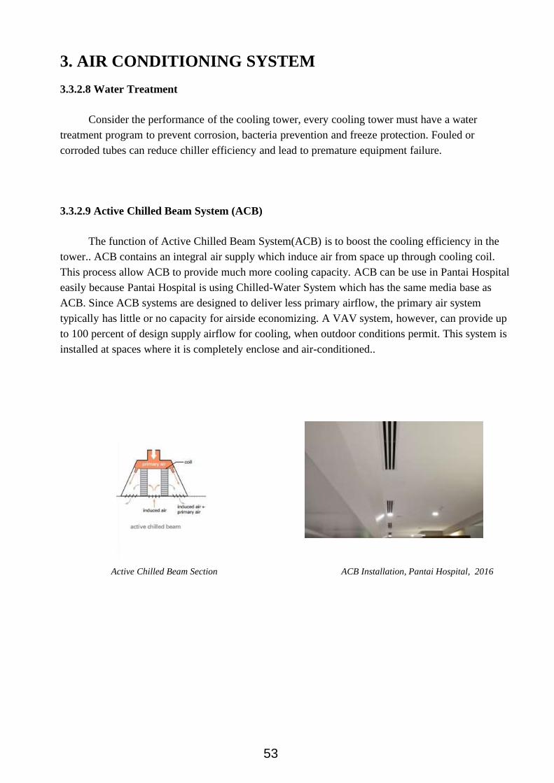
3.3.2.9 Active Chilled Beam System (ACB)
The function of Active Chilled Beam System(ACB) is to boost the cooling efficiency in the
tower.. ACB contains an integral air supply which induce air from space up through cooling coil.
This process allow ACB to provide much more cooling capacity. ACB can be use in Pantai Hospital
easily because Pantai Hospital is using Chilled-Water System which has the same media base as
ACB. Since ACB systems are designed to deliver less primary airflow, the primary air system
typically has little or no capacity for airside economizing. A VAV system, however, can provide up
to 100 percent of design supply airflow for cooling, when outdoor conditions permit. This system is
installed at spaces where it is completely enclose and air-conditioned..
Active Chilled Beam Section ACB Installation, Pantai Hospital, 2016
53
3. AIR CONDITIONING SYSTEM
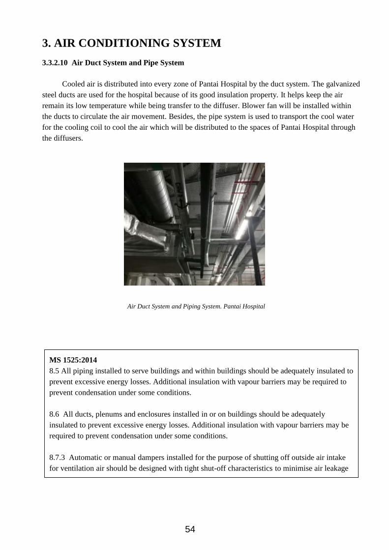
3.3.2.10 Air Duct System and Pipe System
Cooled air is distributed into every zone of Pantai Hospital by the duct system. The galvanized
steel ducts are used for the hospital because of its good insulation property. It helps keep the air
remain its low temperature while being transfer to the diffuser. Blower fan will be installed within
the ducts to circulate the air movement. Besides, the pipe system is used to transport the cool water
for the cooling coil to cool the air which will be distributed to the spaces of Pantai Hospital through
the diffusers.
Air Duct System and Piping System. Pantai Hospital
MS 1525:2014
8.5 All piping installed to serve buildings and within buildings should be adequately insulated to
prevent excessive energy losses. Additional insulation with vapour barriers may be required to
prevent condensation under some conditions.
8.6 All ducts, plenums and enclosures installed in or on buildings should be adequately
insulated to prevent excessive energy losses. Additional insulation with vapour barriers may be
required to prevent condensation under some conditions.
8.7.3 Automatic or manual dampers installed for the purpose of shutting off outside air intake
for ventilation air should be designed with tight shut-off characteristics to minimise air leakage
54

3. AIR CONDITIONING SYSTEM
3.4 Conclusion
In conclusion, air conditioning which often referred as air con or A/C is the process of altering
the properties of air like temperature and humidity to more favorable conditions by cools, (or heat),
cleans, freshens the air and controls its moisture content simultaneously. This helps hospitals to
provide a comfortable environment to the occupants especially patients. The doctors and staff will
also be able to work more comfortably and concentrate on their duty in a better manner.
There are various types of air conditioning systems for different applications such as the
centralized air conditioning system, the district cooling system and the chilled beam system. As
Pantai Hospital is a huge high-rise building, it utilizes the water system which the system uses
chilled water to transport heat energy between the airside, chillers and the outdoors for efficiency
and economic advantages. The centrifugal water chillers include the evaporator, compressor,
condenser and expansion device. Due to the units being placed in the isolated area of the floor or on
top of the building, there is minimum noise production which suits the requirements of the hospital.
Pantai Hospital Kuala Lumpur compiles with the by-law in terms of air distribution. Air
conditioning system has helped in making the environment of the Pantai Hospital livable and
comfortable. It also helps in keeping the environment of the hospital clean and hygienic. The rules
and regulation that they had achieved are :
UBBL-SECTION 41(3) : The provisions of the Third Schedule to these By-laws apply to
buildings which are mechanically ventilated or air-conditioned.
MS 1525:2014 (8.2.1): Air conditioning systems and equipment shall be sized to provide no more
than the space and system loads calculated in accordance with 8.1 above, consistent with
available equipment capacity. Redundancy in the capacity of equipment, if incorporated into
the sizing of the duty equipment, should include efficiency devices such as variable speed
drive, high-efficiency motor, efficient unloading devices, multi compressors etc. so as not to
diminish the equipment/system efficiency when operating at varying loads.
MS 1525:2014 8.2.2 Where chillers are used and when the design load is greater than 1000 kWr,
a minimum of either two chillers or a single multi-compressor chiller should be provided to
meet the required load.
MS 1525: 2014 (8.8) The system design should provide means for balancing the air and water
system such as but not limited to dampers, temperature and pressure test connections and
balancing valves
55

4
MECHANICAL
VENTILATION
SYSTEMINTRODUCTION | REPORT REVIEW | CASE STUDY |
CONCLUSION
by
LOONG BO LIN
TAN JINGWEI

4. MECHANICAL VENTILATION SYSTEM
4.1. Introduction
Ventilation is commonly used to control indoor air quality by diluting and displacing indoor
pollutants. Outdoor air is brought into an enclosed space or an indoor space, and it is distributed
within the space. Besides from diluting the pollutants originating in the indoor space, ventilation in
indoor spaces also provides healthy air for breathing. Ventilation can also be used on thermal
comfort purposes or dehumidification by bringing in outside air to achieve desired indoor
psychrometric conditions. In another word, ventilation can make a huge difference on the
temperature inside an indoor space, it can reduce heat inside an indoor space and provide a cooler air
and provide comfort for the user of the space.
The intentional adoption of the outdoor air can be categorized into either natural ventilation or
mechanical ventilation.
4.1.1. Natural Ventilation System
Natural ventilation is the passive air flow of the outdoor air into an indoor space through designated
openings, such as louvers, windows, doors and etc. Natural ventilation does not require mechanical
component to force air flow from outdoor, it totally depends on passive physical phenomena, such as
wind pressure, velocity, thermal buoyancy force, diffusion, stack effect and etc. Natural ventilation
also depends on climate, building design, human behaviour and etc.
4.1.2. Mechanical Ventilation System
Mechanical ventilation basically uses fans to drive the flow of outdoor air into an indoor space by
pressurization or extracting the indoor air to outside by depressurization. Pressurization can be done
in the case of positively pressurized buildings, while depressurization can be done in the case of
exhaust ventilation systems. In other words, mechanical ventilation works either on supplying air
into an indoor space, or extracting air from an indoor space to the outside. Most mechanical
ventilation combined them both to achieve the desired diluting or cooling effect.
Natural ventilation system. Source: Bilco,
Kenilworth Media Inc., (2017).
Natural ventilation system. Source: American
Institute of Architects, (2012).
57

4. MECHANICAL VENTILATION SYSTEM
4.2. Report Review
The mechanical ventilation system can be categorized into various type of system. The three
categories of the mechanical ventilation system are the supply ventilation system, the extract
ventilation system and the balanced or combined ventilation system.
4.2.1. Supply Ventilation System
The supply ventilation system is a system with mechanical inlet air and natural air extract. The
outdoor air is forced into the indoor space mechanically by using fan, pressurizing the indoor space.
While the air leaks out from the indoor space naturally, it can be leak through the holes in the shell,
bath, range fan ducts and existing intentional fan.
The supply ventilation system has a fan and duct system, it may include adjustable window or wall
vent s in other room. Yet, this system is inexpensive and simple to install. In some sense or cases,
this system is better than an exhaust system since it allows a better control of the air that enters the
indoor space than the exhaust system do. The supply system minimizes the outdoor pollutants in the
indoor spaces. It prevents backdrafting of combustion gases from fireplaces and appliances. It also
allows outdoor air that is introduced into the indoor spaces to be filtered in order to remove pollen
and dust or dehumidified. This step is carried out in order to ensure and provide the humidity
control.
Supply ventilation system. Source: U.S.
Energy Department, (n.d.).
58

4. MECHANICAL VENTILATION SYSTEM
The supply ventilation system pressurizes the indoor spaces, hence it has a potential to cause
moisture problem in cold climate. During winter time, this system can cause warm indoor air to leak
out through the random openings in the exterior walls and ceiling. If the indoor air is humid enough,
moisture may condense in the attic or cold outer parts of the exterior walls, resulting in mildew,
mold and even in decaying. In other words, this system works best in hot and mixed climates.
4.2.2. Extract Ventilation System
The extract ventilation system works by depressurizing the indoor spaces. It exhaust air from the
indoor spaces while make up for the infiltration of air through leaks in the building shells and
intentional passive vents.
Same with the supply ventilation system, the exhaust ventilation system is also simple and
inexpensive to install. This system consists of a single fan connected to a centrally located, single
exhaust point of in the indoor spaces. There might be a better designated exhaust system which is by
connecting the fans to ducts from several rooms where the pollutants are generated, such as
bathrooms. Passive vents through windows or walls can be installed adjustably in other rooms to
introduce fresh air rather than rely entirely on leaks in the building envelope. Passive vents may
require a larger pressure differences than those induced by the ventilation fan to work properly.
Yet, this system may brings in a concern on the pollutants that it might draw in along with the fresh
air, including the radon and mold from a crawl space, dust from an attic, fumes from an attached
garage, flue gases from a fireplace or fossil-fuel-fired water heater and furnace. These pollutants are
a particular concern when bath fans, range fans, clothes dryers are run when an exhaust ventilation
system is also operating.
Extract ventilation system. Source: U.S.
Energy Department, (n.d.).
59

4. MECHANICAL VENTILATION SYSTEM
The exhaust ventilation system does not temper or remove moisture from the make up air before it
enters the indoor spaces. As a result, it contributes to a higher heating and cooling costs compare
with energy recovery ventilation system.
In climate with warm and humid climates, depressurization can draw moist air into building wall
cavities, where it may condense and cause moisture damage to the building. Thus, this system is
most appropriate for cold climates.
4.2.3. Balanced Ventilation System
The balanced ventilation system is also known as the combined ventilation system. This system is
neither pressurize nor depressurize, if installed properly. It introduces and exhausts approximately
equal qualities of the fresh outdoor air and the polluted indoor air.
Usually, a balanced ventilation system has two fans and two duct systems, it could be said that it
actually is the combination of both supply and exhaust ventilation system. Due to the direct outdoor
air supply, some design uses single-point exhaust, since it allows the use of filters in order to remove
dust and pollen from outdoor air before entering the indoor spaces.
Fresh air supply and exhaust vents can be installed in every room, yet it is designed to supply fresh
air to the indoor spaces where the users mostly spend their time in, such as living rooms and
bedrooms. It also exhausts air from rooms where pollutants and moisture are mostly generated, such
as bathroom, kitchen and laundry room.
Balanced ventilation system. Source: U.S.
Energy Department, (n.d.).
60

4. MECHANICAL VENTILATION SYSTEM
This system can usually be found or used in the cinemas, theatres, sport centers, basements, attic,
crawl space and etc. This system achieves slight pressurization in the indoor spaces by using an
extract fan which is smaller than the inlet fan, to prevent dust, draughts and noises. It can supply
fresh air and picks up stale air at multiple point.
Same with both supply and exhaust ventilation system, the balanced ventilation system does not
temper or remove moisture from the make up air before it enters the indoor spaces. Thus, it can also
results in contributing to higher heating and cooling costs. Like the supply system, the outdoor air
needs to be mixed with the indoor air before delivery in order to avoid cold air drafts during winter
time, of course when the uses are located in cold climate places.
This system is appropriate for all climates since it requires two fans and two duct systems. And also,
since it has two fans and two duct systems, it is usually more expensive to install and operate than
the supply and exhaust ventilation system.
4.2.4. Fan Coil Unit
Fan Coil Unit (FCU) is a simple device consisting of a heating and/or a cooling heat exchanger or
coil and fan. This system is used to control the temperature in the indoor spaces where it is installed.
This system can be controlled in two different ways, which is either by manual switch or by a
thermostat. The thermostat controls the throughput of water to the heat charger using a control valve
and the fan speed. This system can be commonly found in residential, commercial and industry
buildings.
Fan Coil Unit. Source: Veris Industry, (2017).
61

4. MECHANICAL VENTILATION SYSTEM
4.3. Case Study
Pantai Hospital Kuala Lumpur uses the three types of mechanical ventilation as well as the FCU in
certain spaces. This is due to different functions, location and specifications of the spaces inside the
building/ The following shows the list of application of ventilation systems:
Fan Coil Unit (FCU)
Supply System
Exhaust System
Balanced / Combined System
4.3.1 Fan Coil Unit (FCU)
In Pantai Hospital, the fan coil are located in the parking lots. The fan coil unit (FCU) is a device
which consists of a heating and cooling coil and fan. It acts as a mechanical ventilation system that
control and regulate the temperature in the space where it's installed.
Due to their simplicity, fan coil units are more economical to install than ducted or central heating
systems with air handling units.
Foil Coil Unit (FCU) installation (As similar to Pantai Hospital)
The FCU at the Pantai Hospital uses a two-pipe fan coil unit. This consists of one supply and one
return pipe. As Malaysia’s climate is hot and humid, the supply pipe supplies cold water to the unit
all the time of the year. The FCU at the commercial area are concealed and installed at the ceiling
void.
62

4. MECHANICAL VENTILATION SYSTEM
4.3.2 Supply Ventilation System
Pantai Hospital uses pressurized system in staircase. Pressurized system is used to prevent smoke
leaking passed closed doors into stairs by inserting clean air into the stair enclosure. The
pressurization of staircase work as the fan located at the top of the staircase push the air through the
gaps around the door.
When there’s a fire, clean air from outside is forced by the Stair Pressurized Fan into the stairwell.
The pressurization is used to push back smoke, keeping the smoke out of the escape route.
The section of a typical pressurized system stairwell.
(As similar to Pantai Hospital)
Source: (“Building Operation WebHelp”, 2016)
According to UBBL 1984 Clause 202 : Pressurized system for staircases
All staircases serving building of more than 45.75 meters height where there is no adequate
ventilation are required shall be provided with staircase pressurization system designed and
installed in accordance with MS 1472.
63

4. MECHANICAL VENTILATION SYSTEM
The pressure relief damper installed on the wall near the staircase.
The fire rated doors can be found at each level of the building.
The door will affect the pressure and causes it drop when opened, sufficient air supply is needed to
ensure the pressure remains as same to prevent the entry of smoke.
64

4. MECHANICAL VENTILATION SYSTEM
4.3.3 Exhaust Ventilation System
The exhaust ventilation system in Pantai Hospital is used in the parking. The parking area at the
hospital has partial natural ventilation due to the absence of some walls, therefore it uses the
exhaust-only ventilation. The exhaust system is responsible to extract the stale air and harmful gases
from vehicles through ductwork. Fresh air is the natural replaced through the openings at the
parking.
The ductwork at the car park are evenly distributed out, connected with mechanical extraction at the
end. As the air condition underground is usually hot, humid and stuffy, the exhaust ventilation
system helps to remove the air out. The ductwork connect from the internal part of the carpark and
direct outwards to the entrance and exit of the basement to expel of air.
A lower level extraction point is also found at the parking, mainly for extraction of carbon monoxide
and other pollutant gases. The extract of air is run by the fan room which is located at the end of the
parking area.
The low extract point that found in the carpark..
The space in the basement carpark where the
aluminum ductwork can be spotted.
65

4. MECHANICAL VENTILATION SYSTEM
4.3.4 Smoke Spill System
Smoke control of a building is important in order to proceed emergency evacuation during fire.
Smoke Spill System is also known as Smoke Extract Ventilation System, this system is protected via
the passive fire protection system. This system will be used when a fire happens. It is used to
remove smoke from the building to enable emergency evacuation and also to improve firefighting.
The Pantai Hospital Kuala Lumpur has a properly constructed smoke spill system which is able to
sustain smoke free circumstances at all occupied levels. Hence, the possible risk of smoke
inhalation, injury and death can be reduced to the least amount.
Smoke Management System, Ceiling Jet Smoke Flow Pattern.
Source: National Research Council Canada, (2000).
The smoke exhaust system built on top of the
roof of the Pantai Hospital KL.
66

4. MECHANICAL VENTILATION SYSTEM
4.3.5 Combined Ventilation System
The kitchen and motor room at Pantai Hospital uses the combined ventilation system due to the
absence of openings in the spaces, hence no natural ventilation.
Ventilation needs to constantly be under control for proper operation of the machines. The lift motor
at Pantai Hospital has no openings. If the space gets overheated it will affect the operation of the
equipment and controls. Therefore, the room uses the combined ventilation system consisting of an
exhaust fan and make-up air for continuous cooling of the room. In addition, the room also uses a
split air conditioner for maximum cooling of the space.
Extract fan in the lift motor room.
Supply air grille in the lift motor room.
According to UBBL 1984 Clause 41 : Mechanical ventilation and air conditioning
Windows and openings allowing uninterrupted air passage are not necessary if the room are
equipped with mechanical ventilation or air conditions.
In case of air-conditioning failure, there should be alternative way to introduce fresh air into
the room within half an hour.
67
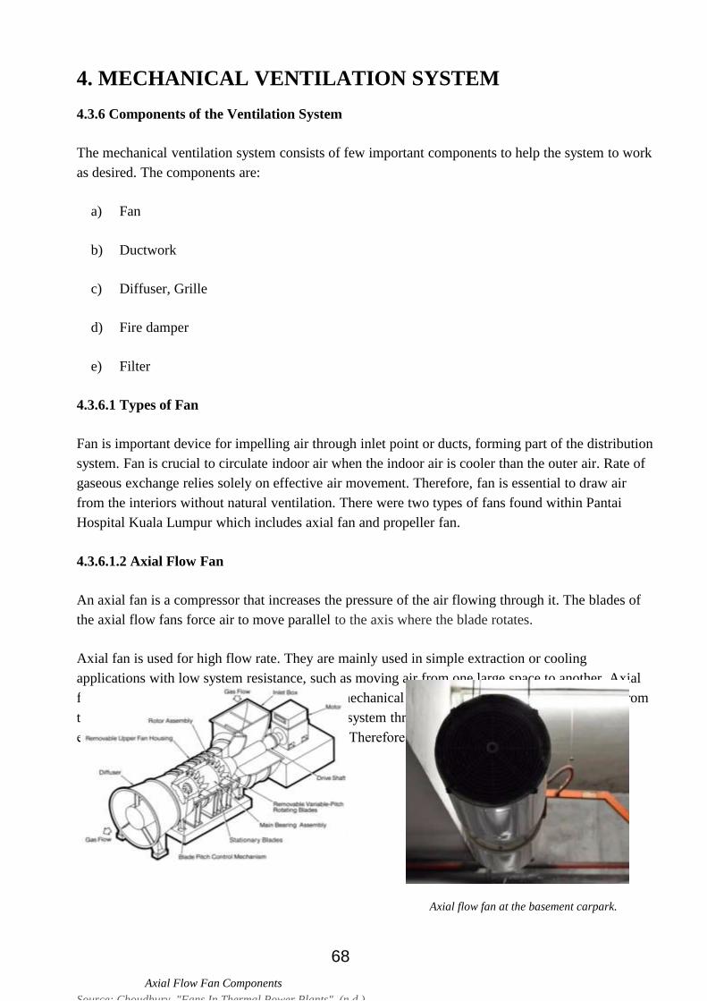
4. MECHANICAL VENTILATION SYSTEM
4.3.6 Components of the Ventilation System
The mechanical ventilation system consists of few important components to help the system to work
as desired. The components are:
a) Fan
b) Ductwork
c) Diffuser, Grille
d) Fire damper
e) Filter
4.3.6.1 Types of Fan
Fan is important device for impelling air through inlet point or ducts, forming part of the distribution
system. Fan is crucial to circulate indoor air when the indoor air is cooler than the outer air. Rate of
gaseous exchange relies solely on effective air movement. Therefore, fan is essential to draw air
from the interiors without natural ventilation. There were two types of fans found within Pantai
Hospital Kuala Lumpur which includes axial fan and propeller fan.
4.3.6.1.2 Axial Flow Fan
An axial fan is a compressor that increases the pressure of the air flowing through it. The blades of
the axial flow fans force air to move parallel to the axis where the blade rotates.
Axial fan is used for high flow rate. They are mainly used in simple extraction or cooling
applications with low system resistance, such as moving air from one large space to another. Axial
fan works in conjunction with the centralized mechanical ventilation system. It extracts hot air from
the basement and channels it to the centralized system through a series of ductwork. Axial fan
extract air work efficiently under low pressure. Therefore, it’s chosen in the basement.
Axial Flow Fan Components
Source: Choudhury, "Fans In Thermal Power Plants", (n.d.).
Axial flow fan at the basement carpark.
68

4. MECHANICAL VENTILATION SYSTEM
4.3.6.1.1 Propeller Fan
Propeller fan is a great device in freeing air discharge from wall and windows. Propeller fan is
commonly used in residential and commercial buildings without ducting. On the other hand,
propeller fan allows large volume of air to the exterior but not allowing air to be force through a
long duct because of low pressure. Propeller fan works better under a small area and its well-known
for economy friendly, ease of installation and low noise level.
Propeller fan can be found in small enclosure room.
Propeller fan can be found in the motor lift room.
According to MS 1525 Code 8.4.1: Temperature Control
Each system should be provided with at least one thermostat for the regulation of temperature.
Each thermostat should be capable of being set by adjustment or selection of sensors over a
minimum range of between 22c to 27c. Multi-stage thermostat should be provided for
equipment exceeding 35/65kWr in conjunction with 8.2.4.
69

4. MECHANICAL VENTILATION SYSTEM
4.3.6.2 Ductwork
Mechanical ventilation uses ductwork for air exchange. The required airflow includes supply air,
return air and exhaust air. As such, air ducts are one method of ensuring adequate indoor air quality
as well as comfort condition. The ductwork used is galvanized ductwork with fiberglass. Galvanized
steel is the most common material used in fabricating ductwork as it provides insulation. Poorly
designed ductwork may result in an opposite reaction, thus defeating its purposes and make air
quality worse. This will increases energy consumption by the machine, affecting building pressure
and having higher utility cost.
Ventilation ducts should not pass through smoke-stop or firefighting lobby less it be enclosed with
fire-resistant elements in which masonry is used or it be fitted with fire dampers. This is to prevent
fire from spreading into another room.
Normally, the ductwork system of carparks, kitchen, and toilets are separated. This is to prevent any
unnecessary foul smells from entering each other’s spaces.
Ductwork in the carpark of Pantai Hospital.
According to UBBL 1984 Clause 99: Cooking facilities in residential building
(2) Where a common vertical kitchen exhaust is provided, the riser shall be continued up
to a mechanical floor or roof for discharge to the open, and shall be constructed with
fire resisting material of at least 2 hours rating with BS476: Part 3.
70

4. MECHANICAL VENTILATION SYSTEM
4.3.6.3 Supply Air Diffuser, Grille
Diffusers are designed for air supply and exhaustion in mechanical ventilation system. They are
located at the edge of the ductwork where the air is being supplied into the room. The construction
gives the possibility of air distribution in various amount and in one or more directions with the help
of ductwork. The grilles are mounted on a dropped ceiling or directly on the air duct system where
the supplied air is released to the room. They do not require any generation of power and are used to
slow the air’s velocity and to enhance its mixing into the surrounding. Diffusers at Pantai Hospital
are concealed to either the ceiling or wall.
Square air diffuser installed on the ceiling in one of the office.
Circular jet outlet taken at the lobby of Pantai Hospital.
According to MS 1525 Code 8.3.1: Separate Air Distribution System
Zones which are expected to operate non-simultaneously for more than 750 hours per year
should be served by separate air distribution system. As an alternative off-house control
should be provided in accordance.
71

4. MECHANICAL VENTILATION SYSTEM
4.3.6.4 Return Air Grille, Fan
Air grilles and fans are designed to remove warm air from interiors at specific period of time to
prevent overheating. Grills installed are adjustable, allowing the person in charge to control the
amount of air going through and shut the room off so furance cannot pull air out out of it. A return
air grille is installed with a filter to trap smaller particulate materials preventing them to go through
ductwork. The limits of the amount of cleaning needed and keeps the system running smoothly,
reducing the risk of clogs caused by dust and other materials.
Return air grille that found in Pantai Hospital.
Return air grille that installed in the ductwork.
72

4. MECHANICAL VENTILATION SYSTEM
4.3.6.5 Fire Damper
Fire Damper is a device installed to prevent the spreading of fire through walls or ducts from one
space to another. Upon detection of heat, the fire damper closes automatically, thus resisting the
passage of flames into other spaces. It also used to interrupt migratory airflow and maintaining the
integrity of the fire rated separation. Fire dampers are usually installed at compartment walls, where
it is at the point of duct penetration from one space to another. Even if the ductwork collapses, the
damper will still attached to the wall, maintain the integrity of the wall.
Containment fire and smoke damper with smoke detector.
Source: Hickey, L. (n.d.). Modulating Control of Fire &
Smoke Dampers in Smoke Control
Fire dampers found at one of the wall of Pantai Hospital.
According to UBBL 1984 Clause 156: Protected shafts as ventilation duct
(1) If a protected shaft serves as, or contains, a ventilating duct-
(a) The duct shall be fitted with automatic fire dampers together with or without
subducts as Australian Standard 1668: Pt. 1:1974, so constructed at such
intervals and in such positions as may be necessary to reduce, so far as
practical, the risk of fire spreading from a compartment to any other
compartment, or such other provision shall be made as will reduce such risk so
far as practicable.
(b) The duct shall not be constructed of, or lined with, any material which
substantially increases such risk.
73

4. MECHANICAL VENTILATION SYSTEM
4.3.6.6 Filter
Filter plays a vital role as a component of the mechanical ventilation system. It is usually located
inside the ductwork or at the inlet grill, it is needed to filter the outdoor air before it is delivered into
the indoor spaces. Filtration is important to keep the air clean, especially for a building where the
health level come in as one of the major concern like Pantai Hospital Kuala Lumpur.
The filter trap and prevent the following components to enter the building:
a) Dust
b) Smoke
c) Bacteria
d) Radon and mold
e) Fumes
f) Fuel gases
Examples of viscous filter in mechanical ventilation system.
Source: M. Arkam C. Munaaim PhD, PEng, IntPE., (2009).
74
4.5 Conclusion
In summary, mechanical ventilation plays an important role in ensuring good indoor air quality as it
will ultimately affect the health of the user in the space. Mechanical ventilation system is a necessity
to ensure constant air exchange within indoor spaces in order to remove pollutants, odour, and water
vapour trapped in interior spaces. Mechanical ventilation system can be categorized into 3 types,
supply ventilation system, exhaust ventilation system and balanced ventilation system. The system
applied in the spaces varies according to the function, size and the capacity of a room. Appropriate
mechanical ventilation system should be assigned correctly to prevent the wastage of energy, cost of
installation and maintenance. Constant maintenance should also be conducted regularly to prevent
energy loss which in result increases utility cost.
The Pantai Hospital Kuala Lumpur has a complete mechanical ventilation system which consists of
the supply ventilation system, exhaust ventilation system, balanced ventilation system, smoke
extract system and FCA with the working components which are the fan, duct system, diffuser and
grille, fire damper and filter. The indoor air circulation improved and the indoor temperature is
controlled in order to ensure the breathing quality and the health of the patients, staffs, visitors and
other users in Pantai Hospital Kuala Lumpur. Hence, the Pantai Hospital Kuala Lumpur achieved the
sufficient mechanical ventilation system in the building.
The Pantai Hospital Kuala Lumpur has achieved the following requirements and regulations:
According to MS 1525 Code 8.4.1: Temperature Control, each system should be provided with at
least one thermostat for the regulation of temperature. Each thermostat should be capable of
being set by adjustment or selection of sensors over a minimum range of between 22c to 27c.
Multi-stage thermostat should be provided for equipment exceeding 35/65kWr in
conjunction with 8.2.4.
According to UBBL 1984 Clause 99: Cooking facilities in residential building, where a common
vertical kitchen exhaust is provided, the riser shall be continued up to a mechanical floor or
roof for discharge to the open, and shall be constructed with fire resisting material of at least
2 hours rating with BS476: Part 3.
According to MS 1525 Code 8.3.1: Separate Air Distribution System, zones which are expected to
operate non-simultaneously for more than 750 hours per year should be served by separate
air distribution system. As an alternative off-house control should be provided in accordance.
4. MECHANICAL VENTILATION SYSTEM
75

4.5 Conclusion
According to UBBL 1984 Clause 156: Protected shafts as ventilation duct, if a protected shaft
serves as, or contains, a ventilating duct-
a. The duct shall be fitted with automatic fire dampers together with or without subducts
as Australian Standard 1668: Pt. 1:1974, so constructed at such intervals and in such
positions as may be necessary to reduce, so far as practical, the risk of fire spreading
from a compartment to any other compartment, or such other provision shall be made
as will reduce such risk so far as practicable.
b. The duct shall not be constructed of, or lined with, any material which substantially
increases such risk.
In addition, according to UBBL regulation (UBBL 2012, Amendments on EE and MS 1525), each
mechanical ventilation system (supply and exhaust) might be furnished with a promptly open switch
or other means for shut off or volume decrease when ventilation is not required. The Pantai Hospital
Kuala Lumpur also achieved this requirement since most of the ventilation system inside the
building are connected to switches to let the user of the building to turn the system off when they are
not in use. Thus, by this current state of the mechanical ventilation system, the Pantai Hospital
Kuala Lumpur has achieved to become a sustainable building.
4. MECHANICAL VENTILATION SYSTEM
76
5
MECHANICAL
TRANSPORTATION
SYSTEMINTRODUCTION | REPORT REVIEW | CASE STUDY |
CONCLUSION
by
ERICA CHIN CHING

5. MECHANICAL TRANSPORTATION SYSTEM
5.1 Introduction
A mechanical transportation system in a building is an energy-using service for the people
and goods to travel from place to place more efficiently, either vertically or horizontally.
Three common mechanical transportation systems are elevators, escalators and travelators.
5.2 Report Review
5.2.1 Elevator (Lift)
Elevator is an example of vertical transportation system, which is a mechanism that lowers
and rises the people or goods to different floors in a multi-storey building. Elevator provides
a vertical circulation for disables particularly in tall buildings. Generally, they are driven by
traction cable and counterweight systems such as a hoist or a hydraulic pump powered by
electric motor. Elevators are installed according to hoist mechanism, building height,
building type, elevator location and special uses.
5.2.1.1 Hoist Mechanism
a. Hydraulic Elevators
Also known as push elevators which are supported by a piston at a bottom of the
elevator that pushes the elevator up. The machine room are usually located at the
lowest level beside the shaft. The 2 main types are holed hydraulic elevators
(conventional) and hole-less hydraulic elevators.
a. Pneumatic Elevators
Pneumatic elevators are raised and lowered are controlling air pressure inside the
chamber where the elevators sits
Hydraulic Elevator Pneumatic Elevator
78

5. MECHANICAL TRANSPORTATION SYSTEM
c. Climbing Elevators
Climbing elevators are normally used in construction sites.
d. Traction Elevators
Traction elevators(pull elevators) are lifted by metal ropes which pass over a pulley
wheel attached to an electric motor above the elevator shaft. A counterweight is
usually existed in in traction elevators to increase efficiency. There are 3 main types
as follows :
- Geared Traction Elevators (the gearbox is attached to the motor which drives the
wheel that moves the ropes, travel speeds up to 500 ft/min)
- Gear-less Traction Elevators (Wheel is attached directly to the motor, travel speed up
to 2000 ft/min)
- Machine-Room-less Elevator (Compact machine, travel speeds up to 590 ft/min)
Gear-less TractionGeared Traction Machine Room-less
79

5. MECHANICAL TRANSPORTATION SYSTEM
5.2.1.2 Building Height
a. Low-Rise building (1 to 3 storeys) - Typically uses Hydraulic Elevator due to their
initial low cost
b. Mid-Rise building (4 to 11 storeys) - Typically uses Geared Traction Elevator
c. High-Rise building (12 storeys and above) - Typically uses Gear-Less Traction
Elevations
5.2.1.3 Building Type
a. Hospital Elevators
b. Residential/ Domestic Elevators
c. Agricultural Elevators
d. Industrial Elevators
e. Commercial Elevators
f. Parking Buildings Elevators
5.2.1.4 Elevator Location
a. Outdoor Elevators
b. Indoor Elevators
5.2.1.5 Special Uses
a. Handicap Elevators
b. Grain Elevators
c. Double-deck Elevator
d. Sky Lobby
5.2.2 Escalator
Escalator is another type of transportation that responsible to move vast amount of people in
a quick and efficent way from one floor to another. Escalator usually does not require any
waiting time like elevator does. It is more practical than elevator. Escalator usually takes the
form of moving staircases80

5. MECHANICAL TRANSPORTATION SYSTEM
5.2.2.2 Configurations
5.2.2.3 Design Consideration
a. Vertical and horizontal distance to be spanned
b. Other building infrastructure
c. The location
d. Traffic pattern
e. Safety
f. Carrying capacity
5.2.2.4 Basic Components
Parallel Crisscross Multiple parallel
Escalators are positioned side by
side
Escalators that have one direction
circulation are ‘stacked’ hence it
minimised the space requirement.
A bank of 2 or more escalators with
differing directions
Vertical & Horizontal distance
81

5. MECHANICAL TRANSPORTATION SYSTEM
5.3 Case Study
The chosen site is the Block A of Pantai Hospital Kuala Lumpur (PHKL). It is an operating
administration office and commercial block of the building. The block consists elevators and
escalators for the convenience of the users there. There are 15 floors included basement in
this building. Ground floor is the commercial area and from 1st floor until 8th floor are the
specialist clinics. The administration offices are located from 9th to11th floors.
5.3.1 Elevators in Pantai Hospital
5.3.1.1 Position in Pantai Hospital Block A
Ground Floor Plan (NTS)
There are three(3) main positions of the elevator that can be identified from the ground floor
plan. Zone A and Zone B elevators are connected to the upper floors whereas the Zone C
elevators are linked to lower floors which are the basement carparks.
82

5. MECHANICAL TRANSPORTATION SYSTEM
a. Zone A
The elevators have access from the basement until the highest floor, the 11th floor.
The frequent users of Zone A are probably the staffs of the offices. Besides, Zone A
is also located nearer to the commercial area which convenient the staffs to grab some
foods during lunch time.
b. Zone B
The elevators have access from basement until the 8th floor only. The frequent users
are those who come to consult the specialists. Zone B also located nearer to the main
entrance and Zone C elevators which is much convenient for the users.
c. Zone C
The elevators can only access to the basement carparks. Zone C is located in between
Zone A and Zone B. The users could be the public users and the staffs.
UBBL 1984 clause 124
A lift shall be provided for non-residential building that exceed 4 storeys above or
below main access level at least one lift shall be provided.
83

5. MECHANICAL TRANSPORTATION SYSTEM
5.3.1.2 Grouping of Elevators
By grouping the elevators, it reduces the cost of installation. Due to its high number of
passenger elevators, they are usually grouped together instead of spreading up. There are few
kinds of grouping arrangement that are found in Pantai Hospital Block A. They are:
a. Single b. Four cars c. Five cars
From our observation, this
elevator is used to deliver
goods or medical wastes
From the plan we learnt that
this type of grouping is found
in Zone A and Zone C. The
human density from the
basement is distributed among
all Zones A, B and C.
According to what we
analysed is that these elevators
in Zone B have higher density
of public users. Furthermore,
it is also considered located at
the core of the circulation..
Hence, this group consist of
five cars.
84

5. MECHANICAL TRANSPORTATION SYSTEM
5.3.1.3 Types of Elevator
We were guided by those mechanical engineers of Pantai Hospital to the motor rooms. We
observed that there are 2 types of elevator’s motor in the same room. Through research, we
managed to identify the types of elevators by recognising a few features.
a. Identified Gear-less Traction Elevator Components
85

5. MECHANICAL TRANSPORTATION SYSTEM
b. Identified Machine Room-less Elevator Components (MRL)
86

5.3.1.4 Types of Elevator’s Door
There are 3 general types of elevator’s door which include two-leaf opening, two-leaf centre
opening and single-leaf side opening. From the observation through this site visit, we were
able to identified two (2) main types of elevator’s door. Those are :
a. Two-leaf Side Opening (provides wider entrance in proportion to width of shaft)
Zone C Elevator’s Door
Diagram shows how it works in a simplified way
5. MECHANICAL TRANSPORTATION SYSTEM
87

5. MECHANICAL TRANSPORTATION SYSTEM
b. Two-leaf Centre Opening
Zone A & Zone B Elevator’s Door
Diagram shows how it works in a simplified way
88

5.3.1.4 Emergency
It is very essential that fire safety and emergency features should be included in the elevator
system. There are few fire safety and emergency features that we found at the elevator area
of Pantai Hospital Kuala Lumpur (PHKL).
5. MECHANICAL TRANSPORTATION SYSTEM
a. Smoke detector b. Emergency Staircase Exit
UBBL 1984 clause 153 Smoke detectors for lift lobbies
(1) All lift lobbies shall be provided with smoke detectors.
c. Firemen Lift d. Emergency Alert
89

5. MECHANICAL TRANSPORTATION SYSTEM
5.3.2 Escalator in Pantai Hospital
5.3.2.1 Position in Pantai Hospital Block A
Ground Floor Plan (NTS)
The only set of escalators spotted in the building. It is located at the main entrance of
the Block A. It links ground floor to the 1st floor. First floor consist of specialist
clinics, endoscopy centre, health screening centre and the heart centre. These
escalators allow the people to have direct access to the upper floor and no waiting
time is needed.
5.3.2.2 Configurations
As there’s only one set of escalators is noticed, there’s only one configuration type is
found. The configuration of the escalators is parallel. The escalator on the left is for
going up and the right one is for coming down.
Escalators in PHKL
90

5. MECHANICAL TRANSPORTATION SYSTEM
5.3.2.3 Identified Components of PHKL’s Escalators
91

5. MECHANICAL TRANSPORTATION SYSTEM
5.4 Conclusion
Both the engineer and architects had worked well to create a great experience for the users by
providing transportation systems in order to let the users travel from one floor to another
safely and efficiently. Considering not only the efficiency of the access to different
mechanical transportation, the designers and constructors did thought about the choice of
technologies they will be using, leading them to lower the budget of maintenance and safety
of the system due to the long life-span of the system. Furthermore, the transportation system
also enhance the circulation of the building to an easy access which can reduce human
density in one place.
All transportation systems in Block A , PHKL
According to UBBL 1984 clause 124, for all non-residential buildings exceeding 4 storeys or
below main access level at least one lift shall be provided. Pantai Hospital Kuala Lumpur
(PHKL) has elevators going up until 11th floors and also elevators to the basement carparks.
This shows that the building has achieved the UBBL. Besides that, another law that was
taken under consideration by PHKL is the UBBL 1984 clause 153 (1), all lift lobbies shall be
provided with smoke detectors. In other words, PHKL building layout is approved lawfully.
To sum up, transportation systems in PHKL are definitely meet the requirement of UBBL
1984. Although we cannot say it is the best transportation systems, but it definitely is a good
design in terms of having few access to the upper floors.
92

6
SUMMARYCONCLUSION

6. SUMMARY
6.1 Conclusion
Since the building (PHKL Block A) is newly built in year 2014, all the equipment of all the systems
stated in the case study are all relatively new and are in good condition.
For the fire protection system alone, the fire protection equipments are proper and new, they also
considered every aspect before they design the building layout plan, in order to avoid more possible
injuries and death, and also to ensure the progression of fire fighting will proceed smoothly when the
fire happens. PHKL has provide complete active and passive fire protection system which will be
needed when fire occurs.
As for the air conditioning system, PHKL has provided a complete system which helps in making
the indoor environment livable and comfortable. This system also helps to make the indoor spaces
clean and hygienic at all time. In other words, the air conditioning system is an essential system to
keep the indoor spaces of the hospital clean and healthy in order to ensure the health of the patients,
staffs, visitors and other users.
The mechanical ventilation system of PHKL is also complete and effective. The mechanical
ventilation system improve the indoor air circulation and the breathing quality of the patients, staffs,
visitors and other users, since the mechanical ventilation system is essential to filter and remove the
bacteria, pollutants, water vapour, odour and other unwanted elements in the air of the indoor spaces
of the hospital. By ensuring the system is effective, the health of the users is also ensured.
As for the mechanical transportation system, PHKL provides complete system for each of the lift
and escalator. The function of the system is always ensured in order to transport the users in the
hospital at all time, especially during emergencies. The safety of the users is also considered in this
system.
The completed systems stated above is designed considering the safety and health of the users at all
times. The maintenance of all of the systems and the equipments are always ensured in order to keep
the users in the hospital safe and healthy as the hospital is a place where health is one of the most
sensitive topic.Therefore, all of the systems above has achieved the requirements and rules and
regulation that is stated and required by the UBBL and also MS1525.
95

6. SUMMARY
According to this case study report of the fire protection system, air conditioning system, mechanical
ventilation system and mechanical transport system in Pantai Hospital Kuala Lumpur (PHKL), we
acknowledge that the PHKL has achieved the following requirements and rules:
1) Fire Protection System (Active and Passive)
UBBL 1984 Section 248 : Marking on wet riser, etc.
UBBL 1984 Section 253 (2) : Emergency power system.
UBBL 1984 Section 155 : Fire mode of operation.
UBBL 1984 Section 237 : Fire Alarm.
UBBL 1984 Section 239 : Voice Communication System.
UBBL 1984 Section 227 : Portable extinguishers.
UBBL 1984 Section 228 : Sprinklers valve.
UBBL 1984 Section 153 : Smoke detectors for lift lobbies.
UBBL 1984 Section 169 : Exit Route.
UBBL 1984 Section 178 : Exist for institutional and other place of assembly.
UBBL 1984 Section 240 : Electrical isolating switch.
UBBL 1984 Section 162 : Fire doors in compartment walls and separating walls.
UBBL 1984 Section 168 : Staircases.
UBBL 1984 Section 172: Emergency exit signs.
Air Conditioning System
UBBL-SECTION 41(3) : Mechanical ventilation and air ventilation.
MS 1525:2014 (8.2.1): Air conditioning systems and equipment shall be sized to
provide no more than the space and system loads calculated in
accordance with 8.1 above, consistent with available equipment
capacity. Redundancy in the capacity of equipment, if
incorporated into the sizing of the duty equipment, should include
efficiency devices such as variable speed drive, high-efficiency
motor, efficient unloading devices, multi compressors etc. so as
not to diminish the equipment/system efficiency when operating
at varying loads.
MS 1525:2014 8.2.2 : Where chillers are used and when the design load is greater
than 1000 kWr, a minimum of either two chillers or a single
multi-compressor chiller should be provided to meet the required
load.
MS 1525: 2014 (8.8) The system design should provide means for balancing the air
95

6. SUMMARY
3) Mechanical Ventilation System
MS 1525 Code 8.4.1: Temperature Control.
UBBL 1984 Clause 99: Cooking facilities in residential building.
MS 1525 Code 8.3.1: Separate Air Distribution System.
UBBL 1984 Clause 156: Protected shafts as ventilation duct.
4) Mechanical Transportation System
UBBL 1984 Section 124 : for all non-residential buildings exceeding 4 storeys or below main
access level at least one lift shall be provided
UBBL 1984 Section 153 : Smoke detectors for lift lobbies
96

7
REFERENCESCITATIONS

References
History
Pantai Hospital Kuala Lumpur. (2011, June 21). Retrieved May 04, 2017, from
https://malaysiahealthcarecom.wordpress.com/partnering-facilities/pantai-hospital-kuala-lumpur/
Pantai Hospital Kuala Lumpur. (2011, June 21). Retrieved May 04, 2017, from
https://malaysiahealthcarecom.wordpress.com/partnering-facilities/pantai-hospital-kuala-lumpur/
Pantai Hospital (Bangsar) Kuala Lumpur (KL). (n.d.). Retrieved May 04, 2017, from https://onedaymd.blogspot.my/p/pantai-
hospital-bangsar-kuala-lumpur-kl.html
(n.d.). Retrieved May 04, 2017, from https://www.pantai.com.my/kuala-lumpur/contact-usocs/building_se
M. (n.d.). Pantai Hospital Kuala Lumpur. Retrieved May 04, 2017, from https://www.medigo.com/en/clinic/malaysia/kuala-
lumpur/pantai-hospital-kuala-lumpur-56e7e6c3832a0
Fire Protection System
Hall, F. (2015). Building Services Handbook. S.l.: Fred Hall & Roger Greeno.
Fire extinguisher types, uses and colours. (2015, February 23). Retrieved May 07, 2017, from
http://blog.sdfirealarms.co.uk/fire-extinguisher-types/
Fire Alarm Systems. (n.d.). Retrieved May 07, 2017, from http://www.firesafe.org.uk/fire-alarms/
Fireman Intercom System Malaysia | Fire Equipment & Training. (n.d.). Retrieved May 07, 2017, from
https://www.firefightingequipment.my/fireman-intercom-system/
Fire extinguishers. (n.d.). Retrieved May 07, 2017, from https://www.marsden-fire-safety.co.uk/resources/fire-extinguishers
Sprinkler Head Types. (n.d.). Retrieved May 07, 2017, from https://www.archtoolbox.com/materials-systems/fire-
supression/sprinklerheadtypes.html
S. (n.d.). Smoke Detector Alarms Save Lives-Which One Is Right For You? Retrieved May 07, 2017, from
http://simplisafe.com/blog/smoke-detector-alarms-guide
Fire and life safety: Emergency lighting. (n.d.). Retrieved May 07, 2017, from http://www.csemag.com/single-article/fire-and-
life-safety-emergency-lighting/924837a1eb33386283ffd5d151cf3701.html
Fire and life safety: Emergency lighting. (n.d.). Retrieved May 07, 2017, from http://www.csemag.com/single-article/fire-and-
life-safety-emergency-lighting/924837a1eb33386283ffd5d151cf3701.html
Air Conditioning System
Chilled Water Central Air Conditioning Systems. Retrived May05, 2017, from
http://www.brighthubengineering.com/hvac/50160-chilled-water-central-air-conditioning-systems/#imgn_1
Chilled Water Air Conditioning, Retrived May 05, 2017, from http://www.airconditioning-systems.com/chilled-water-air-
conditioning.html
98

References
Air conditioning system, Retrieved May 05, 2017, from
https://www.slideshare.net/NooruleInieOsman/air-conditioning-system
Air Conditioning Clinic, Trane, retrieved May 05 2017 from
http://www.tranebelgium.com/files/book-doc/10/fr/10.knzkne7v.pdf
Guestf11b52 Follow. (2009, July 03). Hvac presentation for beginers. Retrieved May 07, 2017, from
https://www.slideshare.net/guestf11b52/hvac-presentation-for-beginers
8 Key Factors That Affect The Selection Of A HVAC System. (n.d.). Retrieved May 07, 2017, from
http://www.myengineeringworld.net/2013/11/8-factors-affecting-hvac-system-selection.html
Guestf11b52 Follow. (2009, July 03). Hvac presentation for beginers. Retrieved May 07, 2017, from
https://www.slideshare.net/guestf11b52/hvac-presentation-for-beginers
Rusty Pipe Mechanical. (n.d.). Retrieved May 07, 2017, from http://www.rustypipe.ca/webapp/p/239/energy-efficiency-
regulations
Heating & Cooling 101. (n.d.). Retrieved May 07, 2017, from http://www.goodmanmfg.com/resources/heating-cooling-101/how-
central-ac-systems-work
Sumit Ranjan, architecture student Follow. (2015, March 09). Air Conditioning System. Retrieved May 07, 2017, from
https://www.slideshare.net/sumiran46muz/airconditioning-working-and-types
Ag Power Web Enhanced Course Materials. (n.d.). Retrieved May 07, 2017, from
https://www.swtc.edu/ag_power/air_conditioning/lecture/basic_cycle.htm
Trane air conditioning clinic. (1966). La Crosse, WI: Trane.
Murphy, J. (2011). Trane Engineers Newsletter volume (Vol. 38-4).
Lonix Building Connectivity. (2009). Example Appliaction Chilled Water Secondart Pumps.
Haines, Roger W., and C. Lewis Wilson. HVAC Systems Design Handbook. 3rd ed. United State of America, New York:
McGraw-Hill Company, 1998. Print.
Mechanical Ventilation System
Whole-House Ventilation. (n.d.). Retrieved May 05, 2017, from https://energy.gov/energysaver/whole-house-ventilation
SUPPLY VS. EXHAUST mechanical VENTILATION. (n.d.). Retrieved May 05, 2017, from http://www.house-
energy.com/House/SupplyVsExhaust.html
Atkinson, J. (1970, January 01). Concepts and types of ventilation. Retrieved May 05, 2017, from
https://www.ncbi.nlm.nih.gov/books/NBK143277/
Government of Canada. National Research Council Canada. (2000, December 25). Construction Technology Updates.
Retrieved May 05, 2017, from http://www.nrc-cnrc.gc.ca/ctu-sc/ctu_sc_n48
99

References
What Types of Ductwork Are There? (2013, August 22). Retrieved May 06, 2017, from http://www.shavitz.com/blog/what-
types-of-ductwork-are-there/
SHIVAJI CHOUDHURY, CHIEF ENGINEER at M P POWER GENERATING CO,JABALPUR Follow. (2012, October 12).
Fans in thermal power plants. Retrieved May 06, 2017, from https://www.slideshare.net/SHIVAJICHOUDHURY/fans-in-
thermal-power-plants
Fundamentals of Smoke Control. (n.d.). Retrieved May 06, 2017, from http://help.sbo.schneider-
electric.com/topics/show.castle?id=10753&locale=en-US&productversion=1.6
Mechanical Ventilation in Buildings - What You Need To Know - TheGreenAge. (2015). TheGreenAge. Retrieved May 06,
2017, from http://www.thegreenage.co.uk/mechanical-ventilation-in-buildings-what-you-need-to-know/
Mechanical ventilation of buildings - Designing Buildings Wiki. (2016). Designbuildings.co.uk. Retrieved May 06, 2017, from
http://www.designbuildings.co.ul/wiki/Mechanical_ventilation_of_buildings
Hickey, L. (n.d.). Modulating Control of Fire & Smoke Dampers in Smoke Control. Retrieved May 06, 2017, from
http://blog.belimo.com/Blog/bid/76528/Modulating-Control-of-Fire-Smoke-Dampers-in-Smoke-Control
Mechanical Transportation System
M. Arkam C. Munaaim PhD, PEng, IntPE., Director (North Office) at Mega Jati Consult Sdn Bhd. Follow. (2009, March 17).
Transportation Systems In Buildings. Retrieved May 6, 2017, from
https://www.slideshare.net/arkam_slideshare/transportation-systems-in-buildings
Transportation system in Lift, Retrieved from, May, 05, 2017
https://www.slideshare.net/NurulAdha2/lift-29150998
Elevators Types and Classification - Part One. (n.d.). Retrieved May 5, 2017, from http://www.electrical-
knowhow.com/2012/04/elevators-types-and-classification-part.html
Lifts for Building, Design Building Wiki, Retrieved from May, 05, 2017
https://www.designingbuildings.co.uk/wiki/Lifts_for_2buildings
Escalator, Design Building Wiki, Retrieved from, May, 05, 2017
https://www.designingbuildings.co.uk/wiki/Escalator
Escalators Basic Components - Part One. (n.d.). Retrieved May 6, 2017, from http://www.electrical-
knowhow.com/2012/04/escalators-basic-components-part-one.html
Hall, F. E. (1994). Building Services & Equipment (2nd ed., Vol. 2, pp. 113-128). England, Harlow: Longman Scientific &
Technical.
Uniform Building By-Laws (UBBL)
UBBL 1984 pdf, Retrieved from May, 05, 2017
https://www.slideshare.net/JoshuaLee68/ubbl-1984-pdf
100