By John W. Kopp · the development of permissible explosives in underground coal mining. This coal...
20
PLEASE DO NOT REMOVE FRCM LIBRARY Bureau of Mines Report of Investigations /1987 Stem m ing Ejection and Burden M ovem ents From Sm all B orehole B lasts By John W. Kopp UNITED STATES DEPARTMENT OF THE INTERIOR
Transcript of By John W. Kopp · the development of permissible explosives in underground coal mining. This coal...

PLEASE D O N O T REMOVE FRCM LIBRARY
B u r e a u o f M i n e s R e p o r t o f I n v e s t i g a t i o n s / 1 9 8 7
S t e m m i n g E j e c t i o n a n d B u r d e n M o v e m e n t s
F r o m S m a l l B o r e h o l e B l a s t s
By John W. Kopp
U N I T E D S T A T E S D E P A R T M E N T O F T H E INTERIOR

R e p o r t o f I n v e s t i g a t i o n s 9 0 8 0
S t e m m i n g E j e c t i o n a n d B u r d e n M o v e m e n t s
F r o m S m a l l B o r e h o l e B l a s t s
B y J o h n W . K o p p
U N I T E D S T A T E S D E P A R T M E N T O F T H E I N T E R I O R
D o n a l d P a u l H o d e l , S e c r e t a r y
B U R E A U O F M I N E S
R o b e r t C . H o r t o n , D i r e c t o r

Library of Congress Cataloging in Publication Data:
Kopp, John W.Stemming ejection and burden movements from small borehole
blasts.
(Report of investlgations/Unlted States Department of the Interior, Bureau of Mines;
9080)
Bibliography: p. IB.
Supt. of Docs, no.; 1 28.23:9080.
1. Blasting. 2, M i n e safety. I, Title, II, Seriss; Report of investigations (United States,
Bureau of Mines); 9080,
TN23.U43 [TN279] 622 s [622'.23] 86-607912

CONTENTS
Abs t r a c t ................... ................... ................................. .............. 1
Introduction.................................................................... ......... . 2
Acknowledgments .............. ......................................... ..................... 3Experimental design and procedure. ........................................................ 3
Results........................................................................................ 4Crater tests with 1-1/2-in-diameter blastholes.................... ................. 4
Other crater tests............................................................ . 9
Comparison of all crater d ata.................................. .............. . 10Conclusions................................... ................................. ........ . 14References........................... ...................................................... . 15
ILLUSTRATIONS
1. Stemming and burden movements of shot S-3............ ......... ................. 5
2. Relative movements of stemming and burden for shot S-3 and associated
explosive gas temperature...... ........ ........................................... 63. Relative movements of stemming and burden for shot S-4 and associated
explosive gas temperature.......................... .................. ........ . 7
4. Relative movements of stemming and burden for shot S - 6 and associatedexplosive gas temperature....... ........................... ................ . 8
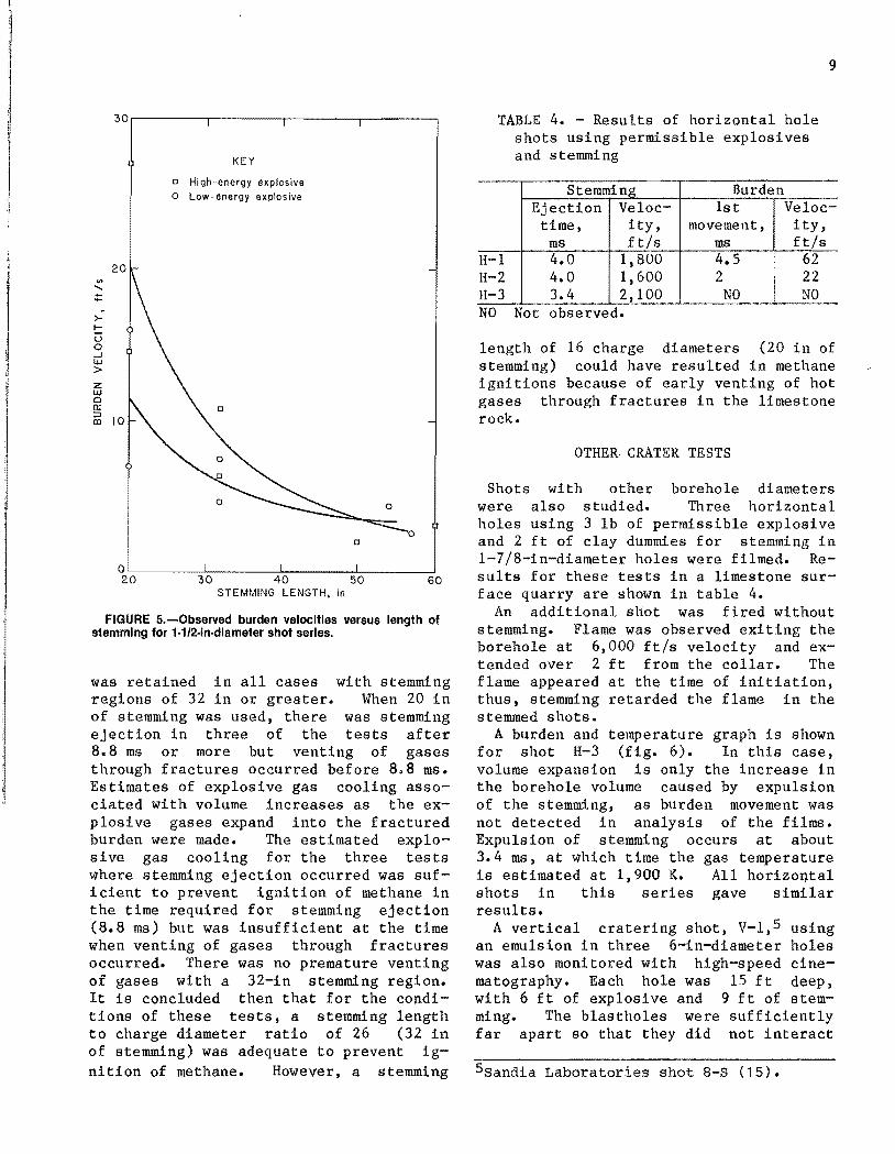
5. Observed burden velocities versus length of stemming for 1-1/2-in-diametershot series............... ............................................... 9
6 . Relative movements of stemming and burden for horizontal shot H-3 andassociated explosive gas temperature.......................... .............. 10
7. Stemming and burden movements for shot V-l . . . . ............. ..................... 10
8 . Relative stemming and burden movements for shot V - l ............................ 119. Burden velocity versus scaled stemming length.......................... 12
10. Rate of burden increase versus scaled charge depth................... . 12
11. S U F E R data from hole 3 of shot V - l ....... ................... ......... . 13
12. SLIFER data from figure 11 replotted to show crushing rate in stemmingr e g i o n . 13
TABLES
1. Properties of explosives used in test series.................................. 4
2. Experimental design and assignment of test numbers.......................... 4
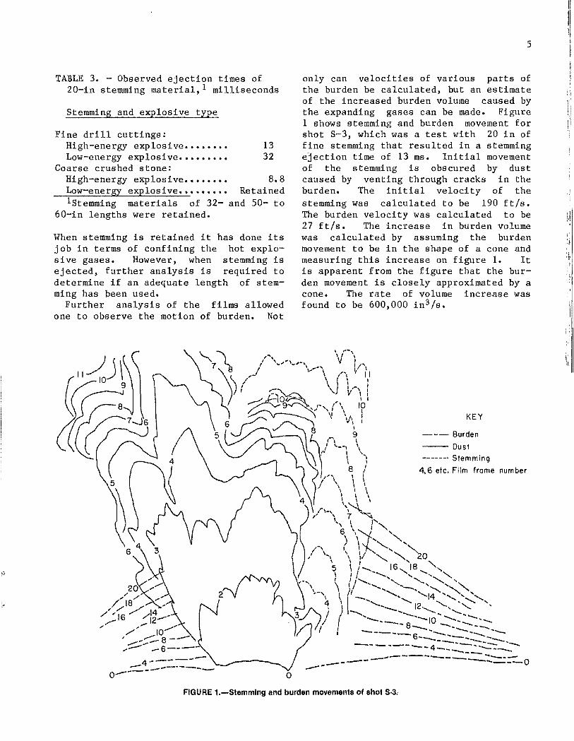
3. Observed ejection times of stemming material................ ................. 5
4» Results of horizontal hole shots using permissible explosivesand stemming. ...................................... .................. ........ 9
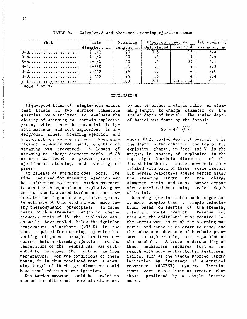
5. Calculated and observed stemming ejection times......................... . 14
Page

UNIT OF MEASURE ABBREVIATIONS USED IN THIS REPORT
atm atmosphere in3 cubic inch
°C degree Celsius in3 /s cubic inch per second
ft foot K Kelvin
ft/s foot per second lb pound
g gram mm millimeter
g/cm3 gram per cubic centimeter ms millisecond
in inch ms/ft millisecond per foot

STEMMING EJECTION AND BURDEN MOVEMENTS FROM SMALL BOREHOLE BLASTS
By John W. K op p1
ABSTRACT
Stemming is used in blasting operations to help contain explosive
gases as long as possible. Stemming can reduce airblast, improve frag
mentation, and reduce the chances of hot explosive gases igniting methane and dust explosions in underground mines. Stemming is required in
underground coal mines but is generally not used in underground metal
and nonmetal mines. Some underground metal and nonmetal mines are classified as gassy and can require special blasting procedures such as the
use of stemming to insure the safety of miners.
The types and amounts of stemming material that are desirable in
underground metal and nonmetal mine blasting to ensure good or improved fragmentation while containing the hot gases are largely unknown. This
Bureau of Mines research examined the effectiveness of differing lengths of stemming by measuring stemming ejection times as related to burden
movement. With properly stemmed blasts, stemming is contained until
some burden movement has occurred.Test blasts at two surface limestone quarries were evaluated using
high-speed photography. For the conditions of these tests, a stemming
length of at least 26 charge diameters was found to prevent premature
stemming ejection. In tests with stemming lengths of 16 charge diame
ters, the stemming was effective but there was early venting of hot gases through fractures in the rock. Further testing with other rock
types, hole diameters, explosive types, and stemming materials as they
affect incendivity is recommended.
1 Mining engineer, Twin Cities Research Center, Bureau of Mines, Minneapolis, MN.

2
INTRODUCTION
Methane emissions in underground mines
can present hazards especially when ignition sources such as explosives are present. The problems associated with blast
ing in underground coal mines have been
dealt with by use of permissible explosives and permissible procedures for
their use. However, methane also occurs
in some noncoal underground mines, particularly oil shale, trona, salt, potash,
copper, limestone, and uranium. At present, blasting operations In such mines
are conducted with a variance from Mine Safety and Health Administration (MSHA) regulations depending on the source of
methane, associated ore body, and the
method of mining. Conventional explosives and blasting agents, rather than
permissible explosives, are normally used
for both practical and economic reasons.A recent Bureau contract^ examined
blasting practices in gassy noncoal
mines. Most of these operations use conventional explosives in standard under
ground blasting practices. Safety is
sometimes insured by evacuating all per
sonnel to the surface during the blast.
However, this is often not practical for
large mines utilizing mining methods such as room-and-pillar. Some mines require
20 or more blasts per day involving large amounts of explosives. In order to main
tain production, blasts must be scheduled
while personnel are working in the mine.
Workman made a number of recommenda
tions for blasting underground with per
sonnel present in the mine. Important
among these was use of stemming to con
tain the hot gases and flame of the ex
plosive in the borehole until expansion
of the burden sufficiently cooled the
gases to prevent Ignition of methane.
Workman made some predictions of the
stemming behavior but this was based only on a simple mathematical model. He rec
ommended that his calculations be con
firmed by field studies.
Stemming is not normally used in non
coal mine underground blasting as its use
adds another step to the blasting
2Contract J0215031? Bauer, Calder, &Workman, Inc.
operation and increases expense. There
can be advantages to the use of stemming,
however, in terms of improved blasting results. Early laboratory tests by Snel-
ling (jO3 demonstrated that high explo
sives were more efficient with the use of stemming than without. Later tests by
the Bureau (2-_7) made in hard-rock drift
rounds also showed that stemming in
creased the efficiency of the explosives used. Sand was the most effective stem
ming material of those studied, although
clay worked well also.
Stemming is a requirement for blasting with permissible explosives in coal
mines. The most common stemming material
is tubes of fire clay. In the 1950's and
1960's, other material was tested by the Bureau (8”_9) including water bags and
special stemming devices. Water bags for stemming in coal mines were originally
developed in Europe in the 1950's
(10-11). A great deal of work on various
stemming materials was done in Europe at this time and is reported by Hofmeister
0 2 ).
Recent stemming research studied the
physical mechanisms involved and the
function of stemming during the blast.
Konya (1 3 ) related the minimum amount of stemming required to retain all blast
products to the pressures developed in the blasthole. This work was done for
the purpose of controlling airblast.
The study of stemming for control of
methane ignitions has been incidental to
the development of permissible explosives
in underground coal mining. This coal
mine research has thus been limited to
small charges of relatively low-energy
explosives. No adequate studies have been conducted of the use of stemming to
prevent methane ignitions in large blast
rounds using conventional explosives.
This Bureau of Mines study was conducted to measure the retention time of
various lengths of stemming in the bore
hole during normal blasting, and to re
late stemming retention time to the
^Underlined numbers in parentheses re
fer to items in the list of references at
the end of this report.

3
burden movement caused by the expanding
gases of the explosive. Tests were con
ducted at two surface limestone quarries, which allowed careful control of the test
blast design variables and adequate
lighting for high-speed photography. Twelve single vertical hole test blasts
(1- 1/2-in-diameter) were detonated in a
factorial experiment with two types of
stemming, two explosives, and three
lengths of stemming. Additional blasts were monitored using 1-7/8-in-diameter
horizontal holes drilled into the base of a highwall and also with 6-ln-dlameter vertical holes drilled into the quarry
floor.
ACKNOWLEDGMENTS
The author is grateful for the assistance of the J. L. Shiely Co. for use of its Carl Larsen quarry. The author also
wishes to thank Atlas Powder Co. and
Sandla National Laboratories for their
cooperation with the large-scale test
shots.
EXPERIMENTAL DESIGN AND PROCEDURE
The primary experimental method chosen for studying stemming behavior was high
speed cinematography. A series of labo
ratory scale tests were conducted to test camera and film analysis procedures and
to assess other methods of observing stemming movement.
The laboratory tests were conducted in
concrete blocks in a blasting shelter,
which limited the maximum charge weight
to 10 g. Drill holes of 1/2-in diameter
were used with depths varied from 5 to 17
in. A PETN-based detonating cord was used as the explosive with charge weights
ranging from 0.1 to 5 g plus the blasting
cap. These initial tests used silica sand for stemming material. Analysis of
these early test films showed that stem
ming movement could be adequately monitored. In addition, movement of burden
could also be calculated and compared
wi t h stemming movement. Set up of the
camera and procedures used to analyze the
films are similar to those discussed by
Blair (14).
Field experiments were filmed with two cameras, a 16-mtn rotating prism camera
capable of speeds up to 1 1 , 0 0 0 frames per
second and a 16-mm registering pin camera
with filming speeds up to 500 frames per second. The registering pin camera has
better resolution than the rotating prism
camera and thus provides a much clearer
picture.
The time of detonation of the explosive
was recorded on film with Nonel^ shock tubing. A known length of shock tubing
was attached to the explosive charge and
passed through the stemming to the surface and was coiled to allow the flash to
be recorded on film. Detonation of the
explosive will initiate the tubing, which
detonates at 6,000 ft/s. Thus the time
of detonation Is determined by noting the flash of the coiled tubing on the film and calculating the time required for the
detonation to reach the surface.
Full-scale field tests were performed at a surface limestone quarry in order to
eliminate lighting problems when filming
with the high-speed cameras. Twelve
cratering shots were detonated for a fac
torial experiment to test two types of
stemming material at three lengths of
stemming and with two explosive types.
A high-energy explosive and a rela
tively low-energy explosive were used for this series of tests. The low energy ex
plosive was chosen to produce results
similar to ANF0. Both explosives were in
1-1/4-in-diameter cartridges. Enough ex
plosive was used in each test to make a
charge 16 in long. The volume of explo
sive was not varied for this test series.
Properties of the explosives used are
shown in table 1.The blastholes were 1-1/2-in diameter
and varied from 36 to 72 in deep. The
holes were drilled vertically in a lime
stone quarry floor. This represents the
worst case for blasting efficiency,
^Reference to specific products does
not imply endorsement by the Bureau of
Mines«

4
TABLE 1. - P ro p e rt ie s of e xp lo s iv e s used in the te s t s e r ie s
Explosive type
Density,g / c m 3
Detoftationvelocity,
ft/s
Relative bulk strength1
Explosive
temperature,K
Borehole
pressure,atm
1.16 15,000 148 3,000 30,000
1.07 10,500 115 2,870 19,000
1.18 16,500 120 2,450 37,000
1.25 18,000 145 3,000 50,000
*ANF0 = 100.
allowing relief in only one direction, upward. Thus, stemming should be ejected more readily than in a normal blast
design.The stemming material consisted of
crushed limestone in one of two sizes. The material was either drill cuttings
screened to less than minus 10 Tyler series mesh size (0.0661 in), or lime
stone gravel between 3/8- and 3/16-in
size. The stemming material was added
above the explosive and filled the hole
to the collar. Table 2 shows stemming
length and type, explosive type, and assignment of shot numbers. The stemming was lightly tamped and had a density of
about 1.5 g / c m 3.
Additional tests were done on larger
diameter blastholes at another limestone
quarry in cooperation with Sandia National Laboratories and Atlas Powder Co.
Two types of blasting were involved. The
first type of blast used 1-7/8-in
diameter horizontal blastholes, 5 ft
long, and drilled into the base of the
highwall. Three 12-in cartridges of a
permissible explosive were loaded into each hole, followed by 2 ft of clay "dum
mies" as used in coal mine blasting. The
shot was monitored with a high-speed camera running at 500 frames per second.
The time of detonation was recorded on
film by use of Nonel shock tubing.
TABLE 2. - Experimental design and assignment of test numbers
Length of stemming..i n . . 20 32 56
Fine drill cuttings: High-energy explosive.
Low-energy explosive..
S-3
S- 6S-2S-12
S— 11
s-lCoarse crushed stone:
High-energy explosive.
Low-energy explosive..
S-4S-5
S- 8S-7
S-10
S-9
The second type of blast was a shot
with three vertical 6-in-diameter holes15 ft deep. An explosive charge of 60 lb
was placed in the bottom 6 ft of each
hole. The upper 9-ft-length was stemmed
with 3/8- to 1-in size crushed limestone
gravel. Each hole was marked with
shock tubing to indicate the time of
detonation.The second test also included San d i a’s
shorted length indication by frequency of
electrical resonance (SLIFER) detonation
velocity detection system in each hole (15). This system measures the rate of
crushing or ionization of a coaxial cable
buried in a blasthole by measuring electronically the length of cable remaining
intact as a function of time as the det
onation front proceeds up the explosive
column. The stemming material is also crushed or compacted, and this rate can
be measured with the SLIFER system.
RESULTS
CRATER TESTS WITH 1-1/2-IN
DIAMETER BLASTHOLES
Twelve cratering tests were conducted
according to the factorial design of
table 2. All shots were monitored with two high-speed cameras, one running at
500 frames per second and the other at
1,000 to 3,000 frames per second. Analy
sis of the films showed that stemming was
usually ejected from the shallow holes.
Results of this analysis are shown in
table 3. With stemming lengths of 20 in
or more, the stemming material was completely contained or it took at least
8 . 8 ms for stemming ejection to occur.
5
TABLE 3. - Observed ejection times of
2 0-in stemming material , 1 milliseconds
Stemming and explosive type
Fine drill cuttings:High-energy explosive......... 13
Low-energy explosive---- ----- 32
Coarse crushed stone:
High-energy explosive......... 8 . 8Low-energy explosive.......... Retained
S t e m m i n g materials of 32- and 50- to
60-in lengths were retained.
When stemming is retained it has done its
job in terms of confining the hot explo
sive gases. However, when stemming is ejected, further analysis is required to
determine if an adequate length of stemming has been used.
Further analysis of the films allowed
one to observe the motion of burden. Not
only can velocities of various parts of
the burden be calculated, but an estimate of the increased burden volume caused by the expanding gases can be made. Figure
1 shows stemming and burden movement for shot S-3, which was a test with 20 in of
fine stemming that resulted in a stemming
ejection time of 13 ms. Initial movement
of the stemming is obscured by dust caused by venting through cracks in the
burden. The initial velocity of the
stemming was calculated to be 190 ft/s.
The burden velocity was calculated to be
27 ft/s. The increase in burden volume
was calculated by assuming the burden
movement to be in the shape of a cone and
measuring this increase on figure 1. It is apparent from the figure that the bur
den movement is closely approximated by a cone. The rate of volume increase was found to be 600,000 i n 3/s.

6
A plot of stemming movement and burden
expansion versus time elapsed from initi
ation of detonation is shown in figure 2 for shot S-3. It is apparent from figure
2 that considerable burden movement occurred before the stemming was completely
ejected after 13 ms. In this case, some cooling of the hot explosive gases has occurred due to volume expansion as the
gasses work their way into the fractured burden region.
An estimate of the amount of explosive
gas cooling can be obtained as follows.
The thermodynamics of the expansion are
assumed to be adiabatic. The expansion
is rapid and allows little time for heat to be exchanged between the gases and
the surrounding rock. From the first law
of thermodynamics it can be shown that
temperature and volume of the gas are re
lated as follows:
1 1
Ti
1 r""" I
Is-*
Vi = t 2 T-lv 2 > (1 )
V i T-l■1- (2 )
where and T 2 are the initial and final
temperatures, Vj and V 2 are the initial and final volumes, and T is the ratio
of the heat capacities of the expanding gases. The actual value of T depends on
the molecular structure of the gases in
volved. Most of the gas products of the explosives used are diatomic and poly
atomic gases— nitrogen, carbon dioxide,
and water vapor. The average value of T for these gases is approximately 1.3.
The equation describing the gas tem
perature line on figure 2 becomes
Ziv
0.3-1 » (3)
which on rearranging becomes
where and Tj are the initial volume
and temperature of the explosive at detonation, V is the increase in volume, and
T is the temperature at that value of
volume. It is now assumed that the gas
2of<r3
(KÜJO.2UJ(-«<<3_l<(J
UJ£KoUJ
" b
10<Uio: o 2
O>
UJQ<r=3CO
TIME, ms
FIGURE 2.—Relative movements of stemming and burden for shot S*3 and associated gas temperature.

7
expands into all of the new volume
created by the expanding burden. The expanding gases may not fill all of the
new spaces created by fracturing of the burden. However, no allowance is made for expansion of the gases into existing
voids or for porosity of the rock. The estimated temperature is thus an approximation but provides some insight into the
phenomena involved.Figure 2 also shows the predicted gas
temperature decrease based on the use of
equation 3 and the burden volume Increase
as determined from analysis of high-speed
films. The stemming remained in the
borehole for 13 ms at which time the gas temperature is estimated to have cooled
from the detonation temperature of3,000 K (2,727° C) to 550 K (277° C),
which would be sufficient to prevent
ignition of a methane-air mixture. The
ignition temperature of methane is 905 K. '
However, from figure 1, it is evident
that venting, probably through a major fracture, occurred before expulsion of the stemming. This occurs at 3 . 8 ms
after initiation. Figure 2 shows that
the explosive gases would have cooled to1,300 K after 3.8 ms, not sufficient
cooling to prevent methane ignition. Be
cause of previous blasting, a significant
fracture pattern existed in this lime
stone rock.A similar analysis was performed for
shots S-4 and S - 6. Results are presented in figures 3 and 4. Figure 3 presents
the analysis of shot S-4 where 20 in of
coarse stemming was ejected using the high-energy explosive. At the time of
stemming expulsion at 8 . 8 ms, the explosive gasses were estimated to have
cooled to 650 K, within a safe tempera
ture range. However, venting of dust and smoke was observed at 3.5 ms after initi
ation. From figure 3, the estimated tem
perature of the gases would be 980 K, above the safe limit. Again, the venting
probably occurred through existing frac
tures in the rock. This shot, and the
previously discussed shot, used a high- energy explosive but different stemming
size. The finer material held longer.
Shot S- 6 had 20 in of fine stemming and
the lower volume-energy explosive. Stem
ming was ejected from shot S-6 , but not
FIGURE 3.—Relative movements of stemming and burden for shot S-4 and associated gas temperature.

8
as soon as with the higher energy explosive (fig* 4). The time for ejection was
32 ms and the estimated gas temperature at that time was 625 K. Venting of smoke
or dust was also observed starting at
4.8 ms after initiation. From figure 4, the estimated gas temperature at the beginning of venting is about 1,300 K, high
enough for a potential methane ignition.Four shots were fired with 32 in of
stemming in each hole. The stemming
remained intact for all these shots. The film analysis did not show any stemming
movement. Burden movement was slower
than in the previous shallower shots. With the exception of shot S-12, no vent
ing of smoke or dust occurred. Also, a
rubble zone of broken material was left at the surface of each hole. The zone
was about 2 ft in diameter for three of
these shots. The shots with 20 in of
stemming left a larger rubble zone on the surface, 2 to 5 ft in diameter. Thus,
the explosive was placed sufficiently close to the surface with 32 in of
stemming to allow fragmentation of the burden.
The final four shots of this series
used stemming lengths of 50 to 60 in. No
stemming movement was detected for any of
these shots. Burden movements were also
smaller than for the previous shots. Figure 5 shows a comparison between bur
den velocities and the length of stemming used in each hole. The type of explosive
used made a difference in burden velocity only at the two shortest stemming
lengths. Differences caused by stemming type were inconclusive.
In this crater test series with
1-1/4-in charges in 1-1/2-in-diameter
blastholes, it was found that stemming
to.
ÜJm3H<a:LUCLsLl )H
<O_J<yHUJce0LÜ1H
30
25
b h ' 2 0 zLd 2 UJ > o
15a
I 10to
— Burden— Stemming ■— Temperature
S t e m m i n g ejected
15 2 0 2 5 3 0TIME, m s
FIGURE 4.—Relative movements of stemming and burden (or shot S-6 and associated gas temperature.
9
S T E M M I N G L E N G T H , in
FIGURE 5.—Observed burden velocities versus length of stemming for 1-1/2-in-dlameter shot series.
was retained in all cases with stemming
regions of 32 in or greater. When 20 in
of stemming was used, there was stemming
ejection in three of the tests after8 , 8 ms or more but venting of gases
through fractures occurred before 8 . 8 ms. Estimates of explosive gas cooling asso
ciated with volume increases as the ex
plosive gases expand into the fractured burden were made. The estimated explo
sive gas cooling for the three tests
where stemming ejection occurred was suf-
lcient to prevent ignition of methane in the time required for stemming ejection
(8 . 8 ms) but was insufficient at the time
w hen venting of gases through fractures
occurred. There was no premature venting of gases with a 32-in stemming region.
It is concluded then that for the condi
tions of these tests, a stemming length to charge diameter ratio of 26 (32 in
of stemming) was adequate to prevent ig
nition of methane. However, a stemming
TABLE 4. - Results of horizontal hole
shots using permissible explosives
and stemming
Stemming Burden
Ejection
time,ms
Velocity, f t/s
1stmovement,
ms
Veloc
ity,ft/s
H-l 4.0 1,800 4.5 62
H—2 4.0 1,600 2 22H-3 3.4 2 , 1 0 0 NO NO
NO Not observed.
length of 16 charge diameters ( 2 0 in of stemming) could have resulted in methane
ignitions because of early venting of hot
gases through fractures in the limestone
rock.
OTHER CRATER TESTS
Shots with other borehole diameters
were also studied. Three horizontal
holes using 3 lb of permissible explosive and 2 ft of clay dummies for stemming in
1-7/8-in-diameter holes were filmed. Results for these tests in a limestone sur
face quarry are shown in table 4.
An additional shot was fired without
stemming. Flame was observed exiting the borehole at 6 , 0 0 0 ft/s velocity and ex
tended over 2 ft from the collar. The
flame appeared at the time of initiation, thus, stemming retarded the flame in the
stemmed shots.A burden and temperature graph is shown
for shot H-3 (fig. 6 ). In this case,
volume expansion is only the increase in
the borehole volume caused by expulsion of the stemming, as burden movement was
not detected in analysis of the films. Expulsion of stemming occurs at about
3.4 ms, at which time the gas temperature
is estimated at 1,900 K. All horizontal
shots in this series gave similar
results.A vertical cratering shot, V - 1 , 5 using
an emulsion in three 6-in-dlameter holes was also monitored with high-speed cinematography. Each hole was 15 ft deep,
with 6 ft of explosive and 9 ft of stem
ming. The blastholes were sufficiently
far apart so that they did not interact
^Sandia Laboratories shot 8-S (15).

1 0
and could be considered as three separate shots. Holes 1 and 2 in this test did not have expulsion of stemming. Hole 3
had stemming movement but not complete expulsion. Stemming and burden movements
for hole 3 are shown in figures 7 and 8 . The portion moving near the collar in
figure 7 is the stemming material and had an initial velocity of 38 ft/s. The bur
den had a velocity of 27 ft/s. Hole 1
behaved in a similar way, with a burden
velocity of 24 ft/s and stemming moving
w ith the burden. Hole 2 showed no burden movement. This was probably because of
escape of the explosive gases through fractures in the rock. No signs of e s
caping gases were evident in the films,
however.
COMPARISON OF ALL CRATER DATA
Comparisons were made between these
larger holes and the 1- 1/2-in-diameter cratering shots. In order to make fair
FIGURE 6.—Relative movements of stemming and burdenfor horizontal shot H-3 and associated explosive gastemperature.
comparisons of shots with differing hole
diameters, the stemming lengths and hole diameters must be normalized. Two methods were used. The first was to simply
divide the stemming length by the charge diameter. The maximum burden velocity
was compared in this way. The results
compared best when plotted logarithmi
cally (fig. 9). Figure 9 shows that the burden velocity data from the 1 - 1 / 2 - i n diameter tests, the horizontal hole
tests, and the 6-in-diameter crater shots can be grouped using a stemming length to charge diameter ratio normalization.
The second method used to compare data from different hole sizes was to plot the
rate of burden volume expansion versus
the scaled depth of burial of the explo
sive charge. The rate of this volume expansion was normalized to account for
differing amounts of explosive by dividing burden volume expansion by the volume
of the explosives in the borehole. This
parameter was found to correlate well
with the scaled depth of burial of each
shot. Scaled depth of burial was found
by dividing the depth in feet to the cen
ter of the top of the explosive charge by
the cube root of the weight in pounds of
the top eight borehole diameters of ex
plosive charge (16). Results of this are shown in figure 10. From figures 9 and
10 it is apparent that the larger hole
sizes fall within the trend of the data and thus the scale factors discussed are
appropriate.
FIGURE 7.—Stemming and burden movements for shot V-1, a 6-in-diameter vertical blasthole.

1 1
_c(DO
kJCD<UJocoz
UJ2z>_la>
UJatr3ID
FIGURE 8.—Relative stemming and burden movements foi shot V-1.
A simple physical model has been sug
gested to predict the time required to eject stemming . 6 This model depends only
on inertia of the stemming material and
not frictional forces to resist movement and thus the acceleration, a, of the
stemming is given by
M(4)
where F is the force exerted on the stem
ming by explosive g a s s e s , and M is the
mass of the stemming. The equation of motion is thus
S = V 0 t + 1/2 a t (5)
where S is distance traveled by the stem
ming, V Q is initial velocity, and t
(time) is seconds. Combining equations4 and 5 with V 0 = 0 gives
. / 2SMV F (6 )
®Work cited in footnote 2 .
The force, F, can be estimated from the
borehole pressure, P, times the cross
sectional area of the hole, A, or
F = PA, (7)
and the mass of stemming equals
M = p s A£, (8 )
where p s is the density of stemming mate
rial, A is the cross sectional area, and
I is the length of stemming. Substitut
ing givesI2S
t = s j --- (9)
This prediction method yields ejection
times for the shots in this investigation as shown in table 5. Also shown in table
5 is the time of first observed stemming
movement and observed time to ejection.
All observed times for ejection were
much longer than the calculated time. In all cases, no stemming movement was ob
served before the calculated time was
past. This method then should only be

12
R A T I O O F S T E M M I N G L E N G T H
T O C H A R G E D I A M E T E R
FIGURE 9.—Burden velocity versus scaled stemming length.
FIGURE 10.—Rate of burden increase versus scaled charge depth.

13
used to obtain an estimate of the minimum
stemming ejection time. Improved estimates will require the addition of fric
tional forces.
A clue to this late stemming movement is also provided by the instrumentation used in shot V - l . These blastholes were
Instrumented with the SLIFER system
to monitor the detonation rate of the explosive. This instrument also observed
the rate of crushing or compaction of the stemming in the borehole. The record for
hole 3 of shot V-l is shown in figure 11.
The first 6 ft of the record shows the
detonation of the explosive. The detonation velocity is approximately 19,000
ft/s. Above 6 ft, the record shows the crushing of the stemming. This crushing
extends to 12- 1 /2 ft from the bottom of * ’the hole, or 6- 1 / 2 ft of stemming, and takes 7.5 ms to complete. The crushing rate rapidly falls from near the detona
tion velocity of the explosive to a value
below the stress wave velocity and then drops to 0 as shown in figure 12. The
time taken for the crushing to propogate through the stemming (7.5 ms) is close to
but somewhat less than the observed time
for the start of stemming movement (10 ms). The stemming appears to be bridging in the hole and preventing move
ment until it is crushed by the pressure
FIGURE 11.—SLIFER data from hole 3 of shot V-1 showing detonation of the explosive column and the crushing rate of the stemming. (From Sandla National Laboratories.)
pulse in the stemming column and only
then does it start to move.
FIGURE 12.—SLIFER data from figure 11 replotted to show crushing rate In stemming region.
14
TABLE 5. - C a lcu la ted and observed stemming e je c t io n tim es
Shot Hole
diameter, in
Stemming length, in
Ejection time, ms 1st stemming
movement, msCalculated Observed
S—3. . . . . . . . . . . . . . . . . . . . 1- 1 /2 20 0.5 13 3.4
S—4.................... 1- 1 /2 20 .5 9 4.6
S—6 .................... 1- 1 /2 20 . 6 32 6 .1H - 1.................... 1-7/8 24 .5 4 2 . 2H— 2....... . . . . . . . . . . . . . 1-7/8 24 .5 4 2 . 0H— 3.................... 1-7/8 24 .5 4 2.4
V—I 1............*...... 6 108 2 .1 Retained 10lHole 3 only
CONCLUSIONS
High-speed films of single-hole crater
test blasts in two surface limestone quarries were analyzed to evaluate the
ability of stemming to contain explosive
gases, which have the potential to ignite methane and dust explosions in underground mines. Stemming ejection and
burden motions were examined. When sufficient stemming was used, ejection of
stemming was prevented. A length of
stemming to charge diameter ratio of 26 or more was found to prevent premature
ejection of stemming, and venting of gases.
If release of stemming does occur, the
time required for stemming ejection may
be sufficient to permit burden movement to start with expansion of explosive gas
es into the fractured burden and the a s
sociated cooling of the explosive gases. An estimate of this cooling was made us
ing thermodynamic principles. In three
tests with a stemming length to charge diameter ratio of 16, the explosive gas
es would have cooled below the ignition
temperature of methane (905 K) in the
time required for stemming ejection but
venting of gases through fractures oc
curred before stemming ejection and the temperature of the vented gas was esti
mated to be above the methane ignition
temperature. For the conditions of these
tests, it is thus concluded that a stemming length of 16 charge diameters could
have resulted in methane ignition.The burden movement could be scaled to
account for different borehole diameters
by use of either a simple ratio of stem
ming length to charge diameter or the scaled depth of burial. The scaled depth
of burial was found by the formula
s d = d/ "xTi,
where SD is scaled depth of burial; d is the depth to the center of the top of the
explosive charge, in feet; and W is the
weight, in pounds, of explosive in the top eight borehole diameters of the
loaded biasthole. Burden movements cor
related with both of these scale factors but burden velocities scaled better using
the stemming length to the charge diameter ratio, and total burden expansion correlated best using scaled depth
of burial.
Stemming ejection takes much longer and is more complex than a simple calcula
tion, based on inertia of the stemming
material, would predict. Reasons for this are the additional time required for
the stress wave to crush the stemming ma
terial and cause it to start to move, and
the subsequent decrease of borehole pres
sure through crushing and expansion of
the borehole. A better understanding of these mechanisms requires further re
search with more sophisticated instrumen
tation, such as the Sandia shorted length
indication by frequency of electrical resonance (SLIFER) system. Ejection
times were three times or greater than those predicted by a simple inertia
model.

15
REFERENCES
1. Snelllng, W. 0., and C. Hall. The
Effect of Stemming on the Efficiency of
Explosives. BuMinea Tech. Paper 17, 1912, 20 pp.
2. Johnson, J. A., W. G. Agnew, and
M. Mosler. Stemming in Metal Mines. Progress Report 1. BuMines RI 3509,1940, 27 pp.
3. _____ . Stemming in Metal Mines.Progress Report 2. BuMines RI 3528,
1940, 39 pp.
4. _____ . Stemming in Metal Mines.Progress Report 3. BuMines RI 3612,1942, 16 pp.
5. Agnew, W. G . , J. A. Johnson, andM. Mosier. Stemming in Metal Mines.
Progress Report 4. BuMines RI 3646,1942, 4 pp.
6 . Johnson, J. A., and W. G. Agnew.
Stemming in Metal Mines. Progress Re
port 5. BuMines RI 3673, 1942, 10 pp.
7. . Stemming in Metal Mines.Progress Report 6. BuMines RI 3693,1943, 38 pp.
8 . Hartmann, I., H. C. Howarth, and
J. Nagy. Experiments on Safety of Incom
bustible Plugs for Stemming Explosives. BuMines RI 4686, 1950, 13 pp.
9. Van Dolah, R. W . , N. E. Hanna, and
R. L. Grant. Relative Efficacy of Stemming Materials in Reducing Incendivity of
Permissible Explosives. BuMines RI 5863,1961, 8 pp.
10. Wood, W. A. Water Stemming Bags
for use With Explosives. Steel & Coal,
1962, v. 185, pp. 556-558.11. Colliery Guardian. Water as a
Stemming Material. V. 218, No. 5, 1970,
pp. 247-253.
12. Hofmeister, W. Der Einflus des
Besatzes und der Lage der Schlagpatrone
auf das Sprengengebnis (The Influence of Stemming and of the Position of the
Primer on the Efficiency of Blasting).
Nobel Hefte, July 1962, pp. 144-184(Engl. sum.).
13. Konya, C. J . , D. Skidmore, and
F. Otuonye. Control of Airblast and E x cessive Ground Vibration From Blasting by
Use of Efficient Stemming (BuMines) grant
G5195034, Oh State Univ.) BuMines OFR 884, June 1981, 199 pp.
14. Blair, B. E. Use of High-Speed
Camera in Blasting Studies. BuMines RI 5584, 1960, 32 pp.
15. Shirey, D. L., J. E. Uhl, and
R. L. Parrish. Atlas Cratering Tests. Ch. in Oil Shale Program QuarterlyReports, October 1984 through March 1985.
Sandla Rep. SAND 85-2768, Sandla National Laboratories, 1986, pp. 5-26.
16. Duvall, W. I., and T. C. Atchison.
Rock Breakage by Explosives. BuMines RI 5356, 1957, 52 pp.
U,S, GOVERNMENT PRINTING OFFICE: 1 9 8 7 • 6 0 5 -0 1 7 /6 0 0 2 9 1 7 9 INT.-BU.0F MlNES.PGH.,PA. 28447