Bluetooth Multi-Speaker Audio Applicationww1.microchip.com/.../BM64-Bluetooth-Multi-Speaker... ·...
47
2018 Microchip Technology Inc. DS00002645A-Page 1 INTRODUCTION Microchip’s Multi-Speaker Bluetooth Audio solution utilizes Microchip proprietary technology to connect a master speaker to one or multiple slave speakers through a modified Bluetooth protocol. Multi-speaker functionality is implemented using Microchip’s BM6x family of modules. One (master) speaker can either be connected to an audio streaming Bluetooth device (smartphone, tablet, laptop, etc.) or its own auxiliary input (AUX/LINE-In jack), and re-transmit either of the two audio sources to one or more speakers acting as a slave. Multi-speaker solutions can be used with Class 1 BM64 modules, which allow for extended range. This is a practical technology for applications such as PA conference systems or wireless audio throughout indoor or outdoor. Multi-speaker can be provisioned to Concert mode (three or more speakers) or in Stereo mode (two speakers). For more details, refer to “Demo Setup” and “Firmware Capabilities/Features”. Figure 1 illustrates a typical Concert mode application where the master speaker is connected to an audio streaming device through Bluetooth. FIGURE 1: CONCERT MODE: MASTER IS CONNECTED TO BLUETOOTH-ENABLED DEVICE THROUGH BLUETOOTH AN2645 Bluetooth ® Multi-Speaker Audio Application
Transcript of Bluetooth Multi-Speaker Audio Applicationww1.microchip.com/.../BM64-Bluetooth-Multi-Speaker... ·...

AN2645Bluetooth® Multi-Speaker Audio Application
INTRODUCTIONMicrochip’s Multi-Speaker Bluetooth Audio solutionutilizes Microchip proprietary technology to connect amaster speaker to one or multiple slave speakersthrough a modified Bluetooth protocol. Multi-speakerfunctionality is implemented using Microchip’s BM6xfamily of modules. One (master) speaker can either beconnected to an audio streaming Bluetooth device(smartphone, tablet, laptop, etc.) or its own auxiliaryinput (AUX/LINE-In jack), and re-transmit either of thetwo audio sources to one or more speakers acting as aslave.
Multi-speaker solutions can be used with Class 1 BM64modules, which allow for extended range. This is apractical technology for applications such as PAconference systems or wireless audio throughoutindoor or outdoor.Multi-speaker can be provisioned to Concert mode(three or more speakers) or in Stereo mode (twospeakers). For more details, refer to “Demo Setup”and “Firmware Capabilities/Features”.Figure 1 illustrates a typical Concert mode applicationwhere the master speaker is connected to an audiostreaming device through Bluetooth.
FIGURE 1: CONCERT MODE: MASTER IS CONNECTED TO BLUETOOTH-ENABLED DEVICE THROUGH BLUETOOTH
2018 Microchip Technology Inc. DS00002645A-Page 1

AN2645
Figure 2 illustrates a typical Concert mode applicationwhere the master is connected to an audio streamingdevice through AUX-In.FIGURE 2: CONCERT MODE: MASTER IS CONNECTED TO AUDIO STREAMING DEVICE THROUGH AUX-IN
Figure 3 illustrates a typical Stereo mode applicationwhere the master is connected to an audio streamingdevice through Bluetooth.
FIGURE 3: STEREO MODE: MASTER IS CONNECTED TO AUDIO STREAMING DEVICE THROUGH BLUETOOTH
2018 Microchip Technology Inc. DS00002645A-Page 2

AN2645
Figure 4 illustrates a typical Stereo mode applicationwhere the master is connected to an audio streamingdevice through AUX-In.FIGURE 4: STEREO MODE: MASTER IS CONNECTED TO AUDIO STREAMING DEVICE THROUGH AUX-IN
There is no limit for the number of slave speakerswhich can connect to the master in Concert mode.
REQUIREMENTS
Documentation• “BM64 EVB User’s Guide” (DS50002514)• “BM62/64 Bluetooth® 4.2 Stereo Audio Module
Data Sheet” (DS60001403)
Software• Firmware: MSPK V1.xx • MCU: PIC18 MSPK V1.x.x• EEPROM Table: Customized EEPROM table
(*.ipf)• Microchip Bluetooth Audio (MBA) App v1.xx
Hardware• BM64 EVB• MCU Programmer: MPLAB REAL ICE™/ICD 3/
PICkit™ 3• 15V power supply• Micro-USB cable• Bluetooth-enabled audio device such as
smartphone, tablet etc.• AUX-In enabled audio streaming device
• Speakers which accepts L+/- and R+/- as input• Android device 6.0 and higher
ToolsMSPK V1.xx package contains all the required tools.
DEMO SETUPIt is mandatory to program BM64 EVB with MSPKV1.xx software. If the BM64 EVB is not programmedwith MSPK V1.xx software before the demo, follow theprocedure from step 1 through step 5 to set up thedemo. If EVB has previously been programmed withMSPK V1.xx then skip step 1.
1. Software UpdateUpdate the firmware and MCU code from the MSPKV1.xx software package. For more information onfirmware and MCU update procedure, refer to “BM64EVB User’s Guide” (DS50002514), Section 3.6 andSection 3.7 respectively. To program the EEPROM,refer to Section 3.5 of “BM64 EVB User’s Guide”(DS50002514). Four EEPROM tables are provided inthe package. If a customer has more than four devicesor needs to customize the setting, then refer toAppendix B: “Customizing UI and DSPParameters”.
2018 Microchip Technology Inc. DS00002645A-Page 3

AN2645
2. ConnectionConnect a speaker to R/L+/- on the BM64 EVB. Onlyone speaker needs to be connected per EVB.3. Power-upConnect all the BM64 EVBs to 15 V supply and shortpress MFB on all the EVBs.
4. InstallationInstall the Microchip Bluetooth Audio App on Android6.0 or higher device. Refer to the procedure inAppendix A: “Android App Installation” to install theAndroid application.
5. ProvisioningTo provision multi-speaker into Concert/Stereo mode, aset of commands needs to be sent from MCU. Thesecommands are sent either through pressing the button
on the BM64 EVB or through Microchip BluetoothAudio App utilizing BLE UART Transparent modecommand.
FUNCTIONALITY OF BUTTONS ON BM64 EVBThe BM64 EVB provides various button functionality:• Short press MFB: To power-on/off BM64 EVB• Long press MFB: To enter into Pairing mode• Long press SW22: To enter into Master/Slave
mode in Concert mode• Short double press SW22: To add a new slave to
the master• Long press SW39: To enter into Master/Slave
mode in Stereo mode• Short press SW40: To toggle audio source
between AUX-In and Bluetooth audio
Figure 5 illustrates the functionality of all the buttonsavailable on the BM64 EVB.
FIGURE 5: BM64 EVB WITH VARIOUS BUTTON FUNCTIONALITY
Note: The Android version of the MicrochipBluetooth Audio App is available in theGoogle Play™ Store and the iOS versionof the app is available in the AppleiTunes® store. Note: Long press is longer than 3 seconds and
short press is shorter than 3 seconds.
2018 Microchip Technology Inc. DS00002645A-Page 4

AN2645
Concert ModeShort press MFB on all the BM64 EVBs. This willpower-on the EVB and initialization will be done. Aflashing LED indicates that the BM64 EVB is poweredup. A “power-on” voice prompt will also be played out.Long press SW22 on all EVBs. The EVB will haveeither solid red or blue LED flashing after a short timeperiod. The EVB with solid red LED is connected as aslave to the EVB with a flashing blue LED as master.The EVB on which SW22 is pressed first is provisionedas master and others are provisioned as slave.To connect the master with a Bluetooth streamingdevice, long press MFB on master (flashing blue LEDon the EVB) to enter into Pairing mode. A “ready topair” voice prompt is played out. Pair with Bluetooth-enabled audio streaming device. The “pairingcompleted” voice prompt will be played out after thepairing is completed with a Bluetooth-enabled devicesuch as smartphone, tablet etc., and flashing blue LEDwill become solid blue on the EVB. Now play music onthe audio streaming device. Music will be heard onmaster and slave speakers.To add a new slave, short double press SW22 on themaster and then long press SW22 on the new slave.The new slave will have solid red LED indicating that itis added in the group. Music will be heard on the newlyadded slave along with master and slave speakers.To play the audio through AUX-In, connect the master(flashing/solid blue LED) with the audio streamingdevice through the AUX-In cable. Play music on theaudio streaming device and the audio will be heard onboth master and slave speakers. If Bluetooth audio wasplaying before inserting the AUX-In, it will pause theBluetooth audio and AUX-In audio will start playing.Press SW40 on the EVB to toggle the audio sourcebetween AUX-In and Bluetooth. When the AUX-Incable is removed, the Bluetooth audio will resume inprevious state.A short press MFB on the master device will power-offmaster and connected slave devices.Stereo ModeShort press MFB on all BM64 EVBs. This will power-onthe EVB and initialization will be done. A flashing LEDindicates that the BM64 EVB is powered-up. A “power-on” voice prompt will also be played out. Long pressSW39 on all EVBs. Initially red LED will flash on allEVBs. The EVB will have either solid red or flashingblue LED after some time period. The EVB with solidred LED is connected as a slave to the EVB withflashing blue LED as master. The EVB on which SW39is pressed first is provisioned as master and theremaining are provisioned as slave.To connect the master with Bluetooth streaming device,long press MFB on master (flashing blue LED) to enterinto pairing mode. A “ready to pair” voice prompt will beplayed out. Pair with Bluetooth-enabled streaming
device, and a “pairing completed” voice prompt will beplayed out. In addition, a flashing blue LED will becomesolid blue on the EVB. Now play music on the audiostreaming device. Music will be heard on master andslave speakers.To play the audio through AUX-In, connect the master(flashing/solid blue LED) with the audio streamingdevice through AUX-In cable. Play music on audiostreaming device, the audio will be heard on bothmaster and slave speakers. If Bluetooth audio isplaying before inserting the AUX-In, it will pause theBluetooth audio and AUX-In audio will start playing.Press SW40 on the EVB to toggle the audio sourcebetween AUX-In and Bluetooth. When the AUX-Incable is removed, the Bluetooth audio will resume in itsprevious state.A short press MFB on the master device will power-offthe master and connected slave device.
CONCERT MODE PROVISIONING USING MICROCHIP BLUETOOTH AUDIO APP1. Press MFB on all the BM64 EVBs. The Android
app can also be used to power on individualBM64 EVB. For more details, refer to AppendixD: “Android App Power Mode”.
2. Open Microchip Bluetooth AudioAndroid App on an Android phone. The fol-lowing screen is displayed, see Figure 6.
2018 Microchip Technology Inc. DS00002645A-Page 5

AN2645
FIGURE 6: MICROCHIP BLUETOOTH AUDIO ANDROID APP3. A list of connectable BLE devices is displayed.Select any one device MCHP_Multi_x (seeFigure 6) and assign the role of master/slave. In
Concert mode, assign one as master and otheras slaves. Select Concert Slave to assign oneof the BM64 EVB as a slave, see Figure 7.
FIGURE 7: SELECTING OPERATIONAL MODE
2018 Microchip Technology Inc. DS00002645A-Page 6
AN2645
4. When the device is selected as a slave/master,“grouping” is displayed as Group Status, seeFigure 8. Then the red LED will start flashing on
the BM64 EVB. Repeat this step for the otherslave EVBs.
FIGURE 8: GROUPING SLAVE/MASTER
5. Select Concert Master to assign one of the BM64 EVB as a master, see Figure 9.
2018 Microchip Technology Inc. DS00002645A-Page 7

AN2645
FIGURE 9: SELECTING CONCERT MASTER6. The red LED will flash on slave and will be con-nected to the master with the flashing blue LED.From the app select Concert Master, see
Figure 9. The “Concert Master” is assigned to aBM64 EVB, see Figure 10.
FIGURE 10: STATUS CONCERT MASTER
2018 Microchip Technology Inc. DS00002645A-Page 8

AN2645
7. From the app, click Audio, select Pairing ModeEnter to enter Pairing mode, see Figure 11. A“ready to pair” voice prompt is played out onmaster BM64 EVB. Select Speaker Connec-tion Connect and a list of discoverable Blue-
tooth devices will be displayed on the Androidphone; select the device with name MCHP_-Multi_x to pair and connect. A “device con-nected” voice prompt is played out the andflashing blue LED becomes solid blue.
FIGURE 11: AUDIO CONNECTION
8. Control the music from the app through MusicControl, see Figure 11. Click Play, and musicwill play on both master and slave speakers.
9. For AUX-In mode, connect an audio streamingdevice with the master (solid/flashing blue LED)through audio AUX-In cable and play music.Music will play on both master and slave speak-ers.
10. To toggle the audio source, click the Togglebutton on the app, as illustrated in Figure 12.
2018 Microchip Technology Inc. DS00002645A-Page 9

AN2645
FIGURE 12: TOGGLE AUDIO SOURCEADDING A NEW SLAVE1. From the app pause the music play. Click the
Setting tab, select Concert Master. A smallwindow will pop up, select Add new slave toadd a new slave, see Figure 13.
2018 Microchip Technology Inc. DS00002645A-Page 10

AN2645
FIGURE 13: ADDING A NEW SLAVE2. Go to Scan mode and click Scan. “Waiting fornew slave” displays, see Figure 14. Select
Concert Slave to add as a slave.
FIGURE 14: SCANNING FOR NEW SLAVE
2018 Microchip Technology Inc. DS00002645A-Page 11

AN2645
3. New slave is added to the master. Click Scanand select Concert Master. Play music from theAudio tab (see Figure 11). Music will be heardon master and slave including newly addedslave.
STEREO MODE PROVISIONING USING MICROCHIP BLUETOOTH AUDIO ANDROID APP1. In Stereo mode two speakers are used, one as
master and another as slave. Stereo mode pro-visioning through the Microchip BluetoothAudio Android App is similar to Concertmode provisioning. Select Stereo Master andStereo Slave from the app, see Figure 15, inplace of Concert mode master and Concertmode slave in step 1 through step 8 (“Concert
Mode Provisioning Using Microchip Blue-tooth Audio App”). Slave will have a solid redLED and master will have flashing/solid blueLED.
2. For AUX-In audio, connect master (solid/flash-ing blue LED) with audio streaming devicethrough AUX-In cable.
3. The AUX-In and the Bluetooth source can betoggled from the app toggle button, as illustratedin Figure 11.
FIGURE 15: PROVISIONING STEREO MODE
QUICK MASTER/SLAVE SETUPThe Microchip Bluetooth Audio App has added a newfeature to establish quick master and slave speakers.1. From the Microchip Bluetooth Audio App, click
Settings, as illustrated in Figure 16.
Note: It is not mandatory that the Bluetoothstreaming device and provisioning devicebe the same. Instead, one Android/iOSdevice can be used for provisioning andanother Bluetooth audio device for musicplay. Provisioning is done through BLE.
2018 Microchip Technology Inc. DS00002645A-Page 12

AN2645
FIGURE 16: QUICK MASTER/SLAVE SETUP2. Select Create Personal Group, as illustrated in Figure 17.
FIGURE 17: CREATING PERSONAL GROUP
2018 Microchip Technology Inc. DS00002645A-Page 13

AN2645
3. Select Stereo/Concert mode from the pop-up window, as illustrated in Figure 18.FIGURE 18: SELECTING STEREO/CONCERT MODE
4. After selecting the mode, the Personal Audiogroup page is displayed. Enter name (any user-defined) and select master and slave speakers,as illustrated in Figure 19.
2018 Microchip Technology Inc. DS00002645A-Page 14

AN2645
FIGURE 19: PERSONAL AUDIO GROUP SETTINGS5. Master and slave speakers will be created. Toplay music, follow step 7 through step 10 from“Concert Mode Provisioning Using Micro-chip Bluetooth Audio App”.
RENAMING SPEAKERThe speaker name can be changed through the app, asillustrated in Figure 20. The change in speaker name ispermanent, i.e. upon power cycle the new speakername is retained.
2018 Microchip Technology Inc. DS00002645A-Page 15

AN2645
FIGURE 20: RENAMING SPEAKER2018 Microchip Technology Inc. DS00002645A-Page 16

AN2645
EQUALIZER SETTINGThe equalizer parameters can be set/changed from theMicrochip Bluetooth Audio App.1. Select Equalizer Settings > Edit to edit theequalizer parameters, as illustrated inFigure 21.
FIGURE 21: EDITING EQUALIZER SETTINGS
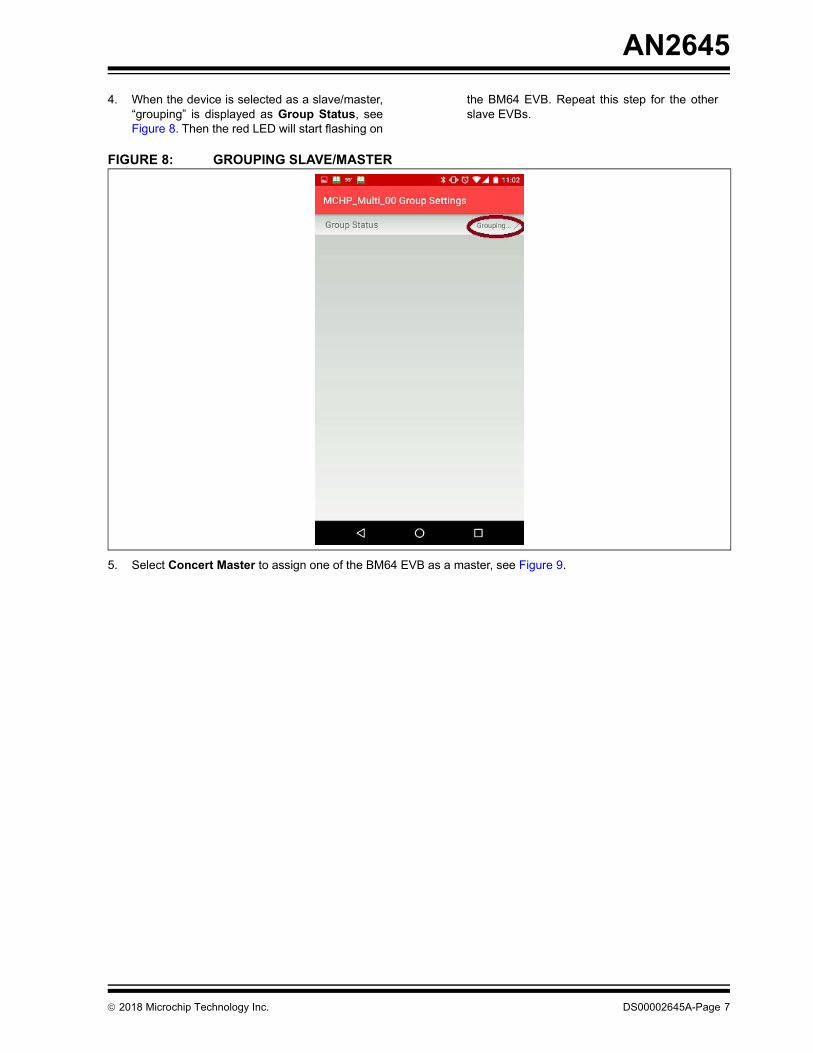
2. Select the standard equalizer parameters from the list, as illustrated in Figure 22.
2018 Microchip Technology Inc. DS00002645A-Page 17
AN2645
FIGURE 22: STANDARD EQUALIZER PARAMETERS LIST3. Select Manual Settings to set the equalizer parameters manually, as illustrated in Figure 23.
FIGURE 23: MANUAL SETTINGS OF EQUALIZER PARAMETERS
2018 Microchip Technology Inc. DS00002645A-Page 18

AN2645
COMMAND PROMPT FEATUREThe Microchip Bluetooth Audio App provides acommand prompt feature. Any command can be sentfrom this command prompt to a connected BM64device as illustrated in Figure 24. This feature is usedto test the customized command such as lightingcontrol, volume control of particular speaker, zoneinformation extraction and reprogramming, etc.
FIGURE 24: COMMAND PROMPT
2018 Microchip Technology Inc. DS00002645A-Page 19

AN2645
FIRMWARE CAPABILITIES/FEATURESThe following features are supported in the multi-speaker V1.xx firmware:Concert ModeIn Concert mode three or more speakers are used. Onespeaker works as master and rest as slaves,connected to the master through Bluetooth. The masteris connected to a Bluetooth-enabled streaming devicethrough Bluetooth (such as smartphone) or to an AUX-In cable. Figure 1 and Figure 2 illustrate a typicalConcert mode application. The audio packets are SBCencoded with medium quality setting and audio packetis not ACKed by slave. There is no feedbackmechanism between slaves and the master. Thebutton press on the master is communicated to theslave, but the button press on the slave affects only theslave speaker on which the button is pressed. TheAUX-In audio is SBC-encoded with medium qualitysettings by the master. It follows the same procedure oftransmission as a Bluetooth packet received by themaster. The AUX-In audio to a slave speaker plays onthe slave speaker only. It is not transmitted to themaster speaker.
Stereo ModeIn Stereo mode two speakers are used. One speakerworks as a master and another as a slave connected tothe master through Bluetooth. The master speaker isconnected to a Bluetooth-enabled streaming devicethrough Bluetooth or through AUX-In cable to an audiostreaming device. Figure 3 and Figure 4 illustrate atypical Stereo mode application. The audio packets areSBC-encoded with a high quality setting and everypacket is ACKed by slave. The lost packet or NACKedpacket is re-transmitted by the master. The buttonpress is synchronized on both the master and slave i.e.play, pause, volume, up/down button press on masterand slave speaker has similar effect. The AUX-In audiois SBC-encoded with high quality settings by master. Itfollows the same procedure of transmission as theBluetooth packet received by the master. The AUX-Inaudio on slave speaker plays on the slave speaker andis not transmitted to the master speaker. The auto-reconnect feature has been enabled in stereo mode;i.e., upon the power cycle of master and slave, theyreconnect.
Zone/GroupThe concept of a zone or group applies when onegroup of speakers cannot connect with another groupof speakers in a multi-speaker system. There is onemaster speaker and multiple slave speakers in a group.Each group is identified by 2 bytes unique ID. This
unique ID can be programmed into a set of speakers tomake them into a group. Many such groups can co-exist without interfering with one another.
Simultaneous Bluetooth and AUX-In AudioBoth Concert mode and Stereo mode supportsimultaneous Bluetooth audio and AUX-In audio. Theaudio source can be toggled by short pressing SW40on the EVB. This functionality is also available on theMicrochip Bluetooth Audio App, see Figure 12.
Programmable AVRCP VersionAudio/Video Remote Control Profile (AVRCP) versioncan be programmed to v1.6/v1.3. For more details,refer to Appendix E: “AVRCP Version”.
AAC CodecAAC codec has been enabled. To enable AdvancedAudio Coding (AAC) codec, refer to Appendix F:“AAC Codec”. The AAC codec is preferred for iOSdevices.
Programmable AUX-In LatencyThe AUX-In latency can be programmed from 20 ms to80 ms. For more details, refer to Appendix G:“Programming AUX-In Latency”.
Auto ReconnectThe Concert/Stereo modes support the auto-reconnectfeature i.e. upon power cycle master and slavereconnects.
Voice Prompt and Hands Free ProfileVoice prompt and HFP are mono by default and can beenabled in Stereo mode (L and R channel). Refer toC.1 “Selecting UI Parameters”.
Note 1: EEPROM address 0x87 and 0x88 isreserved for storing unique ID. A newUART command has been added to pro-gram group ID.
2018 Microchip Technology Inc. DS00002645A-Page 20
AN2645
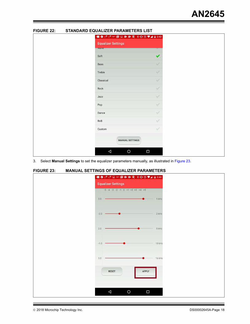
MCU AND CODECThe MSPK V1.xx code is developed and tested on theBM64 EVB. The BM64 EVB contains the BM64module, PIC18 MCU and a Yamaha DSP. However,PIC18 and Yamaha DSP can be replaced by anotherMCU and codec, but the BM6x module is mandatory.MCU and BM64 communicationThe MCU communicates with the BM64 modulethrough UART. A minimum set of hardwareconnections is required to interface MCU to the BM64module. Figure 25 illustrates the minimum connectionsrequired by the relevant hardware pins on the BM64module.
FIGURE 25: MCU AND BM64 EVB INTERFACE
MCU CommandsMCU communicates with the BM64 module throughUART commands. A summary of the commands isprovided in “AudioUARTCommandSet_Summary_table_V2.0x.xlsx” and details of the commands areprovided in “AudioUARTCommandSet_v2 0x.docx”.Both the documents are part of the MSPK V1.xxsoftware package.
PACKAGE CONTENTSThe MSPK V1.xx package contains the following:1. MSPK Firmware V1.xx(.hex file only)2. Sample EEPROM table (*.ipf files), UI file
(.txt) and DSP file (.txt)3. PIC18 MCU code (binary and source code)4. Microchip Bluetooth Audio Android/
iOS App and their source code5. Documentation
- Application Note- AudioUARTCommandSet_v2 0x.docx- AudioUARTCommandSet_Summary_table_
V2.0x.xlsx- Release Note
6. Tools- UI Tool- DSP Tool- isupdate- EEPROM Tool- UART Command Set Tool- MP Tool
MULTI-SPEAKER USER APPLICATION• Museum guided tour• Restaurant• Outdoor entertainment
Note: 44.1K to 48K Audio SRC(ASRC) and 8/16K to 48K Voice SRC(VSRC) are sup-ported in MSPK v1.1. Therefore, anyCodec/Class D amplifier can be used.ASRC and VSRC can be selected in UI,refer to C.1 “Selecting UI Parameters”.
2018 Microchip Technology Inc. DS00002645A-Page 21
AN2645
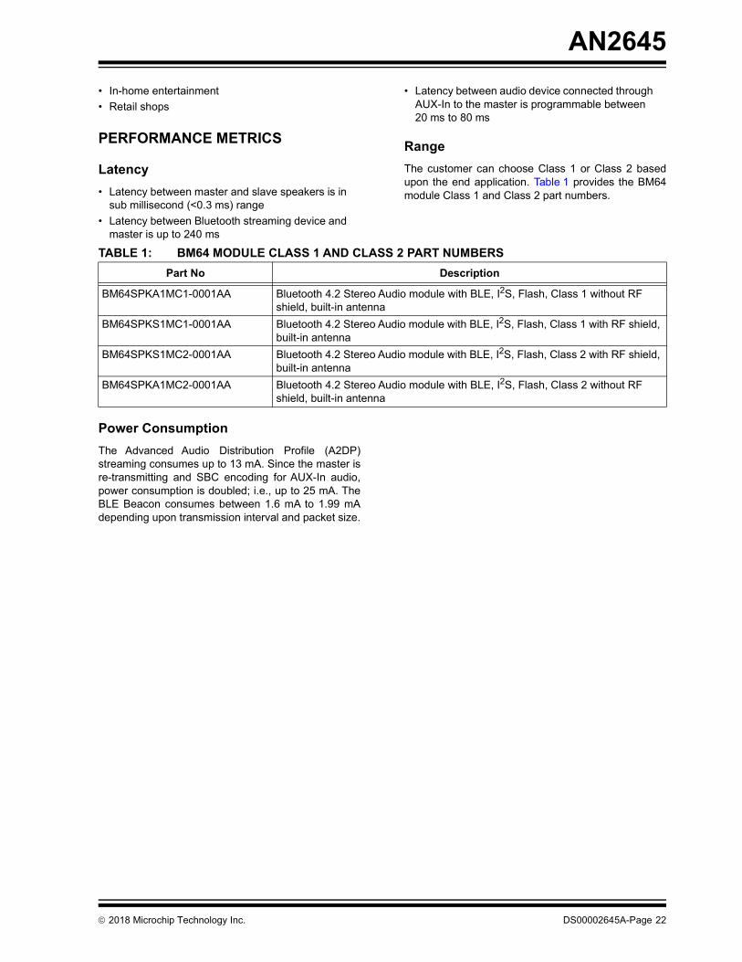
• In-home entertainment• Retail shopsPERFORMANCE METRICS
Latency • Latency between master and slave speakers is in
sub millisecond (<0.3 ms) range• Latency between Bluetooth streaming device and
master is up to 240 ms
• Latency between audio device connected through AUX-In to the master is programmable between 20 ms to 80 ms
RangeThe customer can choose Class 1 or Class 2 basedupon the end application. Table 1 provides the BM64module Class 1 and Class 2 part numbers.
Power ConsumptionThe Advanced Audio Distribution Profile (A2DP)streaming consumes up to 13 mA. Since the master isre-transmitting and SBC encoding for AUX-In audio,power consumption is doubled; i.e., up to 25 mA. TheBLE Beacon consumes between 1.6 mA to 1.99 mAdepending upon transmission interval and packet size.
TABLE 1: BM64 MODULE CLASS 1 AND CLASS 2 PART NUMBERSPart No Description
BM64SPKA1MC1-0001AA Bluetooth 4.2 Stereo Audio module with BLE, I2S, Flash, Class 1 without RF shield, built-in antenna
BM64SPKS1MC1-0001AA Bluetooth 4.2 Stereo Audio module with BLE, I2S, Flash, Class 1 with RF shield, built-in antenna
BM64SPKS1MC2-0001AA Bluetooth 4.2 Stereo Audio module with BLE, I2S, Flash, Class 2 with RF shield, built-in antenna
BM64SPKA1MC2-0001AA Bluetooth 4.2 Stereo Audio module with BLE, I2S, Flash, Class 2 without RF shield, built-in antenna
2018 Microchip Technology Inc. DS00002645A-Page 22

AN2645
APPENDIX A: ANDROID APPINSTALLATIONTo install the application, perform the following steps:1. Connect the Android phone to the computer
using a mini-B USB connector.
FIGURE 26: USB TRANSFER
2. It is recommended to copy the MicrochipBluetooth Audio Android App to the
Download folder of the Android mobile device,see Figure 27.
FIGURE 27: DOWNLOAD FOLDER OF THE ANDROID DEVICE
Note: The latest Android version (Android 6.0and higher) does not show any directory inthe phone. Enable “Transfer files” from thephone to access phone memory, as illus-trated in Figure 26.
2018 Microchip Technology Inc. DS00002645A-Page 23

AN2645
3. From the File Manager of the mobile device,select My Files > All Files > Download > MBA1_x_Android.apk.
After selecting the file, a warning message indi-cating the installation is blocked is displayed,see Figure 28.
FIGURE 28: WARNING MESSAGE: INSTALL BLOCKED
4. Go to Settings to open the Security screen andenable installations from Unknown sources,
and then click OK to confirm the change, seeFigure 29.
FIGURE 29: ENABLE INSTALLATION FROM UNKNOWN SOURCES
2018 Microchip Technology Inc. DS00002645A-Page 24

AN2645
5. A message is displayed requesting whether toinstall an update to the existing application. ClickInstall. A confirmation screen displays when the
application is installed, and then click Open torun the application, see Figure 30.
FIGURE 30: UPDATE AND INSTALL THE APP
6. The app starts scanning and the timeout is for 30seconds. A notification is displayed as “This app
needs location access”, click OK and then selectAllow, as illustrated in Figure 31.
FIGURE 31: LOCATION ACCESS
2018 Microchip Technology Inc. DS00002645A-Page 25
AN2645
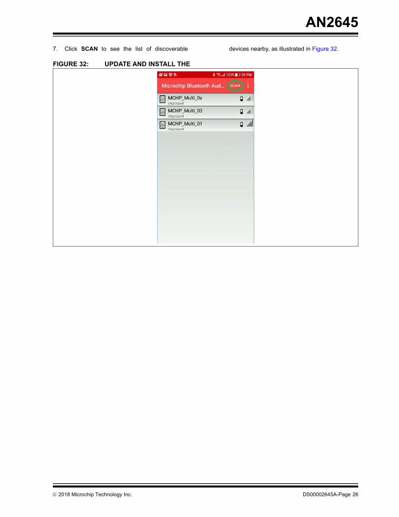
7. Click SCAN to see the list of discoverable devices nearby, as illustrated in Figure 32.FIGURE 32: UPDATE AND INSTALL THE
2018 Microchip Technology Inc. DS00002645A-Page 26

AN2645
APPENDIX B: CUSTOMIZING UIAND DSP PARAMETERS
B.1 Customizing UI ParametersPerform the following steps to customize the UIparameters:
1. Open the UI tool, UITool_IS206xGM_002_nSPK_v1.x.x.exe from Tools\UI Tool.Click Load to load UITool_IS206XGM_002_BM64_EVB.txt from the same folder path andthen click Open, see Figure 33.
FIGURE 33: LOADING UI FILE
2. From the UI tool, click Edit, see Figure 34.
FIGURE 34: EDIT UI PARAMETERS
2018 Microchip Technology Inc. DS00002645A-Page 27
AN2645
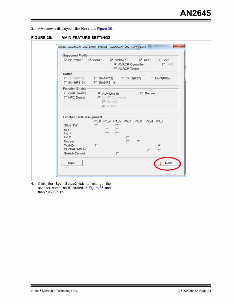
3. A window is displayed, click Next, see Figure 35.FIGURE 35: MAIN FEATURE SETTINGS
4. Click the Sys. Setup2 tab to change thespeaker name, as illustrated in Figure 36 andthen click Finish.
2018 Microchip Technology Inc. DS00002645A-Page 28

AN2645
FIGURE 36: CHANGING SPEAKER NAME5. Click Exit, a window is displayed. From theSave As window, select the file location, and
then click Save, see Figure 37.
FIGURE 37: SAVING UI PARAMETERS
2018 Microchip Technology Inc. DS00002645A-Page 29

AN2645
B.2 Customizing DSP ParametersPerform the following steps to customize the DSPparameters:1. Open the DSP Tool, DSPTool_IS206XGM_002_nSPK05_V1.1_DSP_V1.xx.exe fromtools\DSP Tool. Click Load to load MSPK_BM64_I2S_Master.txt from the same folderpath, as illustrated in Figure 38.
FIGURE 38: LOADING DSP PARAMETERS
2018 Microchip Technology Inc. DS00002645A-Page 30

AN2645
2. Click the I2S/PCM tab and perform the I2S related selection, as illustrated in Figure 39.FIGURE 39: I2S/PCM SETTINGS
2018 Microchip Technology Inc. DS00002645A-Page 31
AN2645
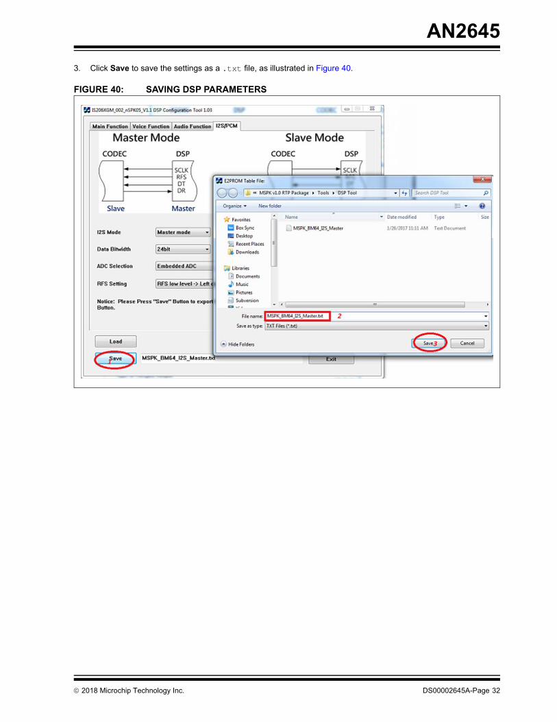
3. Click Save to save the settings as a .txt file, as illustrated in Figure 40.FIGURE 40: SAVING DSP PARAMETERS
2018 Microchip Technology Inc. DS00002645A-Page 32

AN2645
B.3 Creating *.ipf filePerform the following steps to create *.ipf file:1. Open MPET tool, MPET.exe fromTools\MP_Tools_V2.1.xx.xxxx folder,
select UI Patch Only and then click Next, asillustrated in Figure 41.
FIGURE 41: SELECTING .ipf OUTPUT FORMAT
2018 Microchip Technology Inc. DS00002645A-Page 33

AN2645
2. Click Browse and select IS206XGM_002_nSPK05_V1.1_E1.x.x.x_xxxx.bin fromTools\MP_Tools_V2.1.xx.xxxx\issc_default_bin folder. Select the “Load default
bin into IPF” check box and then click Next, asillustrated in Figure 42.
FIGURE 42: LOADING DEFAULT BIN FILE
2018 Microchip Technology Inc. DS00002645A-Page 34

AN2645
3. Click “+” and select MSPK_BM64_I2S_Master.txt and UITool_IS206XGM_002_BM64_EVB.txt, asillustrated in Figure 43 and then click Next.
FIGURE 43: LOADING CUSTOMIZED UI AND DSP PARAMETERS
2018 Microchip Technology Inc. DS00002645A-Page 35

AN2645
4. Select the output file name and path to create the *.ipf file as illustrated in Figure 44, and then click Next.FIGURE 44: SELECTING OUTPUT FILE NAME AND PATH
2018 Microchip Technology Inc. DS00002645A-Page 36

AN2645
5. Click Generate to generate the *.ipf file, as illustrated in Figure 45.FIGURE 45: GENERATE IPF FILE
2018 Microchip Technology Inc. DS00002645A-Page 37

AN2645
6. After generating the *ipf file, click Finish, see Figure 46. The generated *.ipf can be directly programmed intoBM64 modules.
FIGURE 46: IPF FILE GENERATED
2018 Microchip Technology Inc. DS00002645A-Page 38

AN2645
APPENDIX C: CONFIGURING BM64I2S MASTER/SLAVE MODE AT 48 kHz
BM64 I2S can be configured into I2S Master and I2SSlave modes. Appendix B: “Customizing UI andDSP Parameters” describes BM64 configured into I2SMaster mode. This section describes BM64 configuredinto I2S Slave mode.
C.1 Selecting UI ParametersPerform all the steps from B.1 “Customizing UIParameters”. The only difference is enabling AudioSRC and Voice SRC, as illustrated in Figure 47. Clickthe CODEC Setup tab, enable Audio SRC, Voice SRCand then select “External CODEC” as External codec. Voice Prompt and HFP can be enabled in Stereo mode.Enable Tone Stereo and Voice Stereo, as illustrated inFigure 47.
FIGURE 47: CODEC SETUP
Note 1: If “External CODEC” is selected as internal codec then audio will be routed toanalog speaker out.
2: For BM64 I2S Master mode at 48 kHz,refer to C.1 “Selecting UI Parameters”,B.2 “Customizing DSP Parameters”and B.3 “Creating *.ipf file”.
2018 Microchip Technology Inc. DS00002645A-Page 39

AN2645
C.2 Selecting DSP ParametersPerform all the steps from B.2 “Customizing DSPParameters”. The only difference is select I2S modeas Slave mode, as illustrated in Figure 48.FIGURE 48: I2S IN SLAVE MODE
C.3 Creating *.ipf fileFor the procedure to create the *.ipf file, refer to B.3 “Creating *.ipf file”.
2018 Microchip Technology Inc. DS00002645A-Page 40

AN2645
APPENDIX D: ANDROID APPPOWER MODEMicrochip Bluetooth Audio App can also be used forpower-on/off for an individual BM64 speaker. TouchPower to turn on/off the BM64 speaker, as illustrated in
Figure 49. If power is turned off on the master speakerthen it will switch off master and all the connected slavespeakers, similar to the short press of MFB on themaster speaker.
FIGURE 49: POWER MODE ON/OFF
2018 Microchip Technology Inc. DS00002645A-Page 41

AN2645
APPENDIX E: AVRCP VERSION The AVRCP version 1.6/1.3 can be programmed, asillustrated in Figure 50.The volume control is performed on the source inAVRCP v1.3. The absolute volume is sent to sink inAVRCP v1.6.
FIGURE 50: SELECTING AVRCP VERSION
2018 Microchip Technology Inc. DS00002645A-Page 42

AN2645
APPENDIX F: AAC CODECAAC codec can be enabled, as illustrated in Figure 51.FIGURE 51: ENABLE AAC CODEC
2018 Microchip Technology Inc. DS00002645A-Page 43

AN2645
APPENDIX G: PROGRAMMINGAUX-IN LATENCYThe AUX-In latency can be programmed from 20 ms to80 ms, as illustrated in Figure 52.
The value must be 3 times the intended latency value.i.e. for 20 ms delay, Line In Latency = 20*3 = 60.
FIGURE 52: AUX-IN LATENCY
2018 Microchip Technology Inc. DS00002645A-Page 44

AN2645
APPENDIX H: REVISION HISTORYRevision Description DateA • Initial release Feb 2018
2018 Microchip Technology Inc. DS00002645A-Page 45

Note the following details of the code protection feature on Microchip devices:• Microchip products meet the specification contained in their particular Microchip Data Sheet.
• Microchip believes that its family of products is one of the most secure families of its kind on the market today, when used in the intended manner and under normal conditions.
• There are dishonest and possibly illegal methods used to breach the code protection feature. All of these methods, to our knowledge, require using the Microchip products in a manner outside the operating specifications contained in Microchip’s Data Sheets. Most likely, the person doing so is engaged in theft of intellectual property.
• Microchip is willing to work with the customer who is concerned about the integrity of their code.
• Neither Microchip nor any other semiconductor manufacturer can guarantee the security of their code. Code protection does not mean that we are guaranteeing the product as “unbreakable.”
Code protection is constantly evolving. We at Microchip are committed to continuously improving the code protection features of ourproducts. Attempts to break Microchip’s code protection feature may be a violation of the Digital Millennium Copyright Act. If such actsallow unauthorized access to your software or other copyrighted work, you may have a right to sue for relief under that Act.
Information contained in this publication regarding deviceapplications and the like is provided only for your convenienceand may be superseded by updates. It is your responsibility toensure that your application meets with your specifications.MICROCHIP MAKES NO REPRESENTATIONS ORWARRANTIES OF ANY KIND WHETHER EXPRESS ORIMPLIED, WRITTEN OR ORAL, STATUTORY OROTHERWISE, RELATED TO THE INFORMATION,INCLUDING BUT NOT LIMITED TO ITS CONDITION,QUALITY, PERFORMANCE, MERCHANTABILITY ORFITNESS FOR PURPOSE. Microchip disclaims all liabilityarising from this information and its use. Use of Microchipdevices in life support and/or safety applications is entirely atthe buyer’s risk, and the buyer agrees to defend, indemnify andhold harmless Microchip from any and all damages, claims,suits, or expenses resulting from such use. No licenses areconveyed, implicitly or otherwise, under any Microchipintellectual property rights unless otherwise stated.
2018 Microchip Technology Inc.
Microchip received ISO/TS-16949:2009 certification for its worldwide headquarters, design and wafer fabrication facilities in Chandler and Tempe, Arizona; Gresham, Oregon and design centers in California and India. The Company’s quality system processes and procedures are for its PIC® MCUs and dsPIC® DSCs, KEELOQ® code hopping devices, Serial EEPROMs, microperipherals, nonvolatile memory and analog products. In addition, Microchip’s quality system for the design and manufacture of development systems is ISO 9001:2000 certified.
QUALITY MANAGEMENT SYSTEM CERTIFIED BY DNV
== ISO/TS 16949 ==
TrademarksThe Microchip name and logo, the Microchip logo, AnyRate, AVR, AVR logo, AVR Freaks, BeaconThings, BitCloud, CryptoMemory, CryptoRF, dsPIC, FlashFlex, flexPWR, Heldo, JukeBlox, KEELOQ, KEELOQ logo, Kleer, LANCheck, LINK MD, maXStylus, maXTouch, MediaLB, megaAVR, MOST, MOST logo, MPLAB, OptoLyzer, PIC, picoPower, PICSTART, PIC32 logo, Prochip Designer, QTouch, RightTouch, SAM-BA, SpyNIC, SST, SST Logo, SuperFlash, tinyAVR, UNI/O, and XMEGA are registered trademarks of Microchip Technology Incorporated in the U.S.A. and other countries.ClockWorks, The Embedded Control Solutions Company, EtherSynch, Hyper Speed Control, HyperLight Load, IntelliMOS, mTouch, Precision Edge, and Quiet-Wire are registered trademarks of Microchip Technology Incorporated in the U.S.A.Adjacent Key Suppression, AKS, Analog-for-the-Digital Age, Any Capacitor, AnyIn, AnyOut, BodyCom, chipKIT, chipKIT logo, CodeGuard, CryptoAuthentication, CryptoCompanion, CryptoController, dsPICDEM, dsPICDEM.net, Dynamic Average Matching, DAM, ECAN, EtherGREEN, In-Circuit Serial Programming, ICSP, Inter-Chip Connectivity, JitterBlocker, KleerNet, KleerNet logo, Mindi, MiWi, motorBench, MPASM, MPF, MPLAB Certified logo, MPLIB, MPLINK, MultiTRAK, NetDetach, Omniscient Code Generation, PICDEM, PICDEM.net, PICkit, PICtail, PureSilicon, QMatrix, RightTouch logo, REAL ICE, Ripple Blocker, SAM-ICE, Serial Quad I/O, SMART-I.S., SQI, SuperSwitcher, SuperSwitcher II, Total Endurance, TSHARC, USBCheck, VariSense, ViewSpan, WiperLock, Wireless DNA, and ZENA are trademarks of Microchip Technology Incorporated in the U.S.A. and other countries.SQTP is a service mark of Microchip Technology Incorporated in the U.S.A.Silicon Storage Technology is a registered trademark of Microchip Technology Inc. in other countries.GestIC is a registered trademark of Microchip Technology Germany II GmbH & Co. KG, a subsidiary of Microchip Technology Inc., in other countries. All other trademarks mentioned herein are property of their respective companies.© 2018, Microchip Technology Incorporated, All Rights Reserved. ISBN: 978-1-5224-2682-0
DS00002645A-Page 46

DS00002645A-page 47 2017 Microchip Technology Inc.
AMERICASCorporate Office2355 West Chandler Blvd.Chandler, AZ 85224-6199Tel: 480-792-7200 Fax: 480-792-7277Technical Support: http://www.microchip.com/supportWeb Address: www.microchip.comAtlantaDuluth, GA Tel: 678-957-9614 Fax: 678-957-1455Austin, TXTel: 512-257-3370 BostonWestborough, MA Tel: 774-760-0087 Fax: 774-760-0088ChicagoItasca, IL Tel: 630-285-0071 Fax: 630-285-0075DallasAddison, TX Tel: 972-818-7423 Fax: 972-818-2924DetroitNovi, MI Tel: 248-848-4000Houston, TX Tel: 281-894-5983IndianapolisNoblesville, IN Tel: 317-773-8323Fax: 317-773-5453Tel: 317-536-2380Los AngelesMission Viejo, CA Tel: 949-462-9523Fax: 949-462-9608Tel: 951-273-7800 Raleigh, NC Tel: 919-844-7510New York, NY Tel: 631-435-6000San Jose, CA Tel: 408-735-9110Tel: 408-436-4270Canada - TorontoTel: 905-695-1980 Fax: 905-695-2078
ASIA/PACIFICAustralia - SydneyTel: 61-2-9868-6733China - BeijingTel: 86-10-8569-7000 China - ChengduTel: 86-28-8665-5511China - ChongqingTel: 86-23-8980-9588China - DongguanTel: 86-769-8702-9880 China - GuangzhouTel: 86-20-8755-8029 China - HangzhouTel: 86-571-8792-8115 China - Hong Kong SARTel: 852-2943-5100 China - NanjingTel: 86-25-8473-2460China - QingdaoTel: 86-532-8502-7355China - ShanghaiTel: 86-21-3326-8000 China - ShenyangTel: 86-24-2334-2829China - ShenzhenTel: 86-755-8864-2200 China - SuzhouTel: 86-186-6233-1526 China - WuhanTel: 86-27-5980-5300China - XianTel: 86-29-8833-7252China - XiamenTel: 86-592-2388138 China - ZhuhaiTel: 86-756-3210040
ASIA/PACIFICIndia - BangaloreTel: 91-80-3090-4444 India - New DelhiTel: 91-11-4160-8631India - PuneTel: 91-20-4121-0141Japan - OsakaTel: 81-6-6152-7160 Japan - TokyoTel: 81-3-6880- 3770 Korea - DaeguTel: 82-53-744-4301Korea - SeoulTel: 82-2-554-7200Malaysia - Kuala LumpurTel: 60-3-7651-7906Malaysia - PenangTel: 60-4-227-8870Philippines - ManilaTel: 63-2-634-9065SingaporeTel: 65-6334-8870Taiwan - Hsin ChuTel: 886-3-577-8366Taiwan - KaohsiungTel: 886-7-213-7830Taiwan - TaipeiTel: 886-2-2508-8600 Thailand - BangkokTel: 66-2-694-1351Vietnam - Ho Chi MinhTel: 84-28-5448-2100
EUROPEAustria - WelsTel: 43-7242-2244-39Fax: 43-7242-2244-393Denmark - CopenhagenTel: 45-4450-2828 Fax: 45-4485-2829Finland - EspooTel: 358-9-4520-820France - ParisTel: 33-1-69-53-63-20 Fax: 33-1-69-30-90-79 Germany - GarchingTel: 49-8931-9700Germany - HaanTel: 49-2129-3766400Germany - HeilbronnTel: 49-7131-67-3636Germany - KarlsruheTel: 49-721-625370Germany - MunichTel: 49-89-627-144-0 Fax: 49-89-627-144-44Germany - RosenheimTel: 49-8031-354-560Israel - Ra’anana Tel: 972-9-744-7705Italy - Milan Tel: 39-0331-742611 Fax: 39-0331-466781Italy - PadovaTel: 39-049-7625286 Netherlands - DrunenTel: 31-416-690399 Fax: 31-416-690340Norway - TrondheimTel: 47-7289-7561Poland - WarsawTel: 48-22-3325737 Romania - BucharestTel: 40-21-407-87-50Spain - MadridTel: 34-91-708-08-90Fax: 34-91-708-08-91Sweden - GothenbergTel: 46-31-704-60-40Sweden - StockholmTel: 46-8-5090-4654UK - WokinghamTel: 44-118-921-5800Fax: 44-118-921-5820
Worldwide Sales and Service
10/25/17