BM64 Evaluation Board (EVB) User’s Guideww1.microchip.com/downloads/en/DeviceDoc/50002514B.pdfBM64...
84
2016-2018 Microchip Technology Inc. DS50002514B BM64 Evaluation Board (EVB) User’s Guide
Transcript of BM64 Evaluation Board (EVB) User’s Guideww1.microchip.com/downloads/en/DeviceDoc/50002514B.pdfBM64...

2016-2018 Microchip Technology Inc. DS50002514B
BM64 Evaluation Board (EVB)User’s Guide
DS50002514B-Page 2 2016-2018 Microchip Technology Inc.
Information contained in this publication regarding deviceapplications and the like is provided only for your convenienceand may be superseded by updates. It is your responsibility toensure that your application meets with your specifications.MICROCHIP MAKES NO REPRESENTATIONS ORWARRANTIES OF ANY KIND WHETHER EXPRESS ORIMPLIED, WRITTEN OR ORAL, STATUTORY OROTHERWISE, RELATED TO THE INFORMATION,INCLUDING BUT NOT LIMITED TO ITS CONDITION,QUALITY, PERFORMANCE, MERCHANTABILITY ORFITNESS FOR PURPOSE. Microchip disclaims all liabilityarising from this information and its use. Use of Microchipdevices in life support and/or safety applications is entirely atthe buyer’s risk, and the buyer agrees to defend, indemnify andhold harmless Microchip from any and all damages, claims,suits, or expenses resulting from such use. No licenses areconveyed, implicitly or otherwise, under any Microchipintellectual property rights unless otherwise stated.
Note the following details of the code protection feature on Microchip devices:
• Microchip products meet the specification contained in their particular Microchip Data Sheet.
• Microchip believes that its family of products is one of the most secure families of its kind on the market today, when used in the intended manner and under normal conditions.
• There are dishonest and possibly illegal methods used to breach the code protection feature. All of these methods, to our knowledge, require using the Microchip products in a manner outside the operating specifications contained in Microchip’s Data Sheets. Most likely, the person doing so is engaged in theft of intellectual property.
• Microchip is willing to work with the customer who is concerned about the integrity of their code.
• Neither Microchip nor any other semiconductor manufacturer can guarantee the security of their code. Code protection does not mean that we are guaranteeing the product as “unbreakable.”
Code protection is constantly evolving. We at Microchip are committed to continuously improving the code protection features of ourproducts. Attempts to break Microchip’s code protection feature may be a violation of the Digital Millennium Copyright Act. If such actsallow unauthorized access to your software or other copyrighted work, you may have a right to sue for relief under that Act.
Microchip received ISO/TS-16949:2009 certification for its worldwide headquarters, design and wafer fabrication facilities in Chandler and Tempe, Arizona; Gresham, Oregon and design centers in California and India. The Company’s quality system processes and procedures are for its PIC® MCUs and dsPIC® DSCs, KEELOQ® code hopping devices, Serial EEPROMs, microperipherals, nonvolatile memory and analog products. In addition, Microchip’s quality system for the design and manufacture of development systems is ISO 9001:2000 certified.
QUALITY MANAGEMENT SYSTEM CERTIFIED BY DNV
== ISO/TS 16949 ==
Trademarks
The Microchip name and logo, the Microchip logo, AnyRate, AVR, AVR logo, AVR Freaks, BeaconThings, BitCloud, CryptoMemory, CryptoRF, dsPIC, FlashFlex, flexPWR, Heldo, JukeBlox, KEELOQ, KEELOQ logo, Kleer, LANCheck, LINK MD, maXStylus, maXTouch, MediaLB, megaAVR, MOST, MOST logo, MPLAB, OptoLyzer, PIC, picoPower, PICSTART, PIC32 logo, Prochip Designer, QTouch, RightTouch, SAM-BA, SpyNIC, SST, SST Logo, SuperFlash, tinyAVR, UNI/O, and XMEGA are registered trademarks of Microchip Technology Incorporated in the U.S.A. and other countries.
ClockWorks, The Embedded Control Solutions Company, EtherSynch, Hyper Speed Control, HyperLight Load, IntelliMOS, mTouch, Precision Edge, and Quiet-Wire are registered trademarks of Microchip Technology Incorporated in the U.S.A.
Adjacent Key Suppression, AKS, Analog-for-the-Digital Age, Any Capacitor, AnyIn, AnyOut, BodyCom, chipKIT, chipKIT logo, CodeGuard, CryptoAuthentication, CryptoCompanion, CryptoController, dsPICDEM, dsPICDEM.net, Dynamic Average Matching, DAM, ECAN, EtherGREEN, In-Circuit Serial Programming, ICSP, Inter-Chip Connectivity, JitterBlocker, KleerNet, KleerNet logo, Mindi, MiWi, motorBench, MPASM, MPF, MPLAB Certified logo, MPLIB, MPLINK, MultiTRAK, NetDetach, Omniscient Code Generation, PICDEM, PICDEM.net, PICkit, PICtail, PureSilicon, QMatrix, RightTouch logo, REAL ICE, Ripple Blocker, SAM-ICE, Serial Quad I/O, SMART-I.S., SQI, SuperSwitcher, SuperSwitcher II, Total Endurance, TSHARC, USBCheck, VariSense, ViewSpan, WiperLock, Wireless DNA, and ZENA are trademarks of Microchip Technology Incorporated in the U.S.A. and other countries.
SQTP is a service mark of Microchip Technology Incorporated in the U.S.A.
Silicon Storage Technology is a registered trademark of Microchip Technology Inc. in other countries.
GestIC is a registered trademark of Microchip Technology Germany II GmbH & Co. KG, a subsidiary of Microchip Technology Inc., in other countries.
All other trademarks mentioned herein are property of their respective companies.
© 2016-2018, Microchip Technology Incorporated, All Rights Reserved.
ISBN: 978-1-5224-2765-0

BM64 EVB USER’S GUIDE Object of Declaration
BM64 Evaluation Board
2016-2018 Microchip Technology Inc. DS50002514B - Page 3
BM64 EVB User’s Guide
NOTES:
DS50002514B - Page 4 2016-2018 Microchip Technology Inc.

BM64 EVB USER’S GUIDE
Table of Contents
Chapter 1. Introduction1.1 Kit Contents .................................................................................................. 131.2 BM64 EVB Features ..................................................................................... 15
Chapter 2. Hardware2.1 Hardware Features ....................................................................................... 17
Chapter 3. Getting Started3.1 Requirements ............................................................................................... 233.2 Getting Started with BM64 EVB ................................................................... 243.3 Application Demonstration ........................................................................... 253.4 Configuring BM64 Module ............................................................................ 273.5 Updating EEPROM Parameters ................................................................... 503.6 Updating Flash Code .................................................................................... 563.7 Updating MCU Parameters .......................................................................... 64A.1 Reference Schematics ................................................................................. 69
2016-2018 Microchip Technology Inc. DS50002514B - Page 5

BM64 EVB User’s Guide
NOTES:
DS50002514B - Page 6 2016-2018 Microchip Technology Inc.

BM64 EVB USER’S GUIDE
Preface
INTRODUCTION
This chapter contains general information that will be useful to know before using the BM64 Evaluation Board (EVB). Items discussed in this chapter include:
• Document Layout• Conventions Used in this Guide• Recommended Reading• The Microchip Web Site• Development Systems Customer Change Notification Service• Customer Support• Document Revision History
DOCUMENT LAYOUT
This document describes how to use the BM64 EVB, as a development tool to emulate and debug firmware on a target board. This user’s guide is composed of the following chapters:
• Chapter 1. “Introduction” provides an overview of the BM64 EVB and its features.
• Chapter 2. “Hardware” provides hardware details of the BM64 EVB.
• Chapter 3. “Getting Started” provides information about how to establish the Bluetooth® connection using the BM64 EVB and how to configure the BM64 module using various tools.
• Appendix A. “Schematics” provides the BM64 EVB reference schematics.
NOTICE TO CUSTOMERS
All documentation becomes dated, and this manual is no exception. Microchip tools and documentation are constantly evolving to meet customer needs, so some actual dialogs and/or tool descriptions may differ from those in this document. Please refer to our web site (www.microchip.com) to obtain the latest documentation available.
Documents are identified with a “DS” number. This number is located on the bottom of each page, in front of the page number. The numbering convention for the DS number is “DSXXXXXXXXA”, where “XXXXXXXX” is the document number and “A” is the revision level of the document.
For the most up-to-date information on development tools, see the MPLAB® X IDE online help. Select the Help menu, and then Topics to open a list of available online help files.
2016-2018 Microchip Technology Inc. DS50002514B - Page 7

BM64 EVB User’s Guide
CONVENTIONS USED IN THIS GUIDE
This manual uses the following documentation conventions:
DOCUMENTATION CONVENTIONS
Description Represents Examples
Italic characters Referenced books MPLAB IDE User’s Guide
Emphasized text ...is the only compiler...
Initial caps A window the Output window
A dialog the Settings dialog
A menu selection select Enable Programmer
Quotes A field name in a window or dialog
“Save project before build”
Underlined, italic text with right angle bracket
A menu path File > Save
Bold characters A dialog button Click OK
A tab Click the Power tab
Text in angle brackets < > A key on the keyboard Press <Enter>, <F1>
Plain Courier New Sample source code #define START
Filenames autoexec.bat
File paths c:\mcc18\h
Keywords _asm, _endasm, static
Command-line options -Opa+, -Opa-
Bit values 0, 1
Constants 0xFF, ‘A’
Italic Courier New A variable argument file.o, where file can be any valid filename
Square brackets [ ] Optional arguments mcc18 [options] file [options]
Curly brackets and pipe character: { | }
Choice of mutually exclusive arguments; an OR selection
errorlevel {0|1}
Ellipses... Replaces repeated text var_name [, var_name...]
Represents code supplied by user
void main (void){ ...}
Notes A Note presents information that we want to re-emphasize, either to help you avoid a common pitfall or to make you aware of operating differences between some device family members. A Note can be in a box, or when used in a table or figure, it is located at the bottom of the table or figure. Note 1: This is a note used in a
table.
Note: This is a standard note box.
CAUTION
This is a caution note.
DS50002514B - Page 8 2016-2018 Microchip Technology Inc.

Preface
RECOMMENDED READING
This user’s guide describes how to use the BM64 EVB. The following Microchip document is available and recommended as supplemental reference resources.
BM62/64 Data Sheet (DS60001403)
Refer to this document for detailed information on BM64 module. Reference information found in this data sheet includes:
• BM64 module features and pin configurations
• Electrical Specifications
• Reference Circuits
THE MICROCHIP WEB SITE
Microchip provides online support via our web site at: http://www.microchip.com. This web site makes files and information easily available to customers. Accessible by most Internet browsers, the web site contains the following information:
• Product Support – Data sheets and errata, application notes and sample programs, design resources, user’s guides and hardware support documents, latest software releases and archived software
• General Technical Support – Frequently Asked Questions (FAQs), technical support requests, online discussion groups, Microchip consultant program member listings
• Business of Microchip – Product selector and ordering guides, latest Microchip press releases, listings of seminars and events; and listings of Microchip sales offices, distributors and factory representatives
2016-2018 Microchip Technology Inc. DS50002514B - Page 9

BM64 EVB User’s Guide
DEVELOPMENT SYSTEMS CUSTOMER CHANGE NOTIFICATION SERVICE
Microchip’s customer notification service helps keep customers current on Microchip products. Subscribers will receive e-mail notification whenever there are changes, updates, revisions or errata related to a specified product family or development tool of interest.
To register, access the Microchip web site at www.microchip.com, click on Customer Change Notification and follow the registration instructions.
The Development Systems product group categories are:
• Compilers – The latest information on Microchip C compilers and other language tools
• Emulators – The latest information on the Microchip in-circuit emulator, MPLAB REAL ICE™
• In-Circuit Debuggers – The latest information on the Microchip in-circuit debugger, MPLAB ICD 3
• MPLAB X IDE – The latest information on Microchip MPLAB X IDE, the Windows® Integrated Development Environment for development systems tools
• Programmers – The latest information on Microchip programmers including the PICkit™ 3 development programmer
CUSTOMER SUPPORT
Users of Microchip products can receive assistance through several channels:
• Distributor or Representative
• Local Sales Office
• Field Application Engineer (FAE)
• Technical Support
Customers should contact their distributor, representative or Field Application Engineer (FAE) for support. Local sales offices are also available to help customers. A listing of sales offices and locations is included in the back of this document.
Technical support is available through the web site at: http://support.microchip.com.
DS50002514B - Page 10 2016-2018 Microchip Technology Inc.

Preface
DOCUMENT REVISION HISTORY
Revision A (June 2016)
This is the initial released version of this document.
Revision B (March 2018)
This revision includes the following updates:
• Updated 3.2 “Getting Started with BM64 EVB”
• Updated Figure 3-9 and Figure 3-11
• Added Figure 3-12 and Figure 3-13
Minor updates to text and formatting were incorporated throughout the document.
2016-2018 Microchip Technology Inc. DS50002514B - Page 11

BM64 EVB User’s Guide
NOTES:
DS50002514B - Page 12 2016-2018 Microchip Technology Inc.

BM64 EVB USER’S GUIDE
Chapter 1. Introduction
Thank you for purchasing a BM64 Evaluation Board (EVB). This document provides detailed information about the Microchip BM64 EVB.
The BM64 EVB enables the user to evaluate and demonstrate the functionalities of the BM64 module. The BM64 EVB includes status LEDs and an integrated configuration and programming interface for plug-and-play capability, which enables rapid prototyping and faster time to market.
Along with the BM64 EVB, software tools and applications are provided to demonstrate the Bluetooth connections to the on-board BM64 module with options for configuring or programming it.
This chapter includes the following topics:
1.1 “Kit Contents”
1.2 “BM64 EVB Features”
1.1 KIT CONTENTS
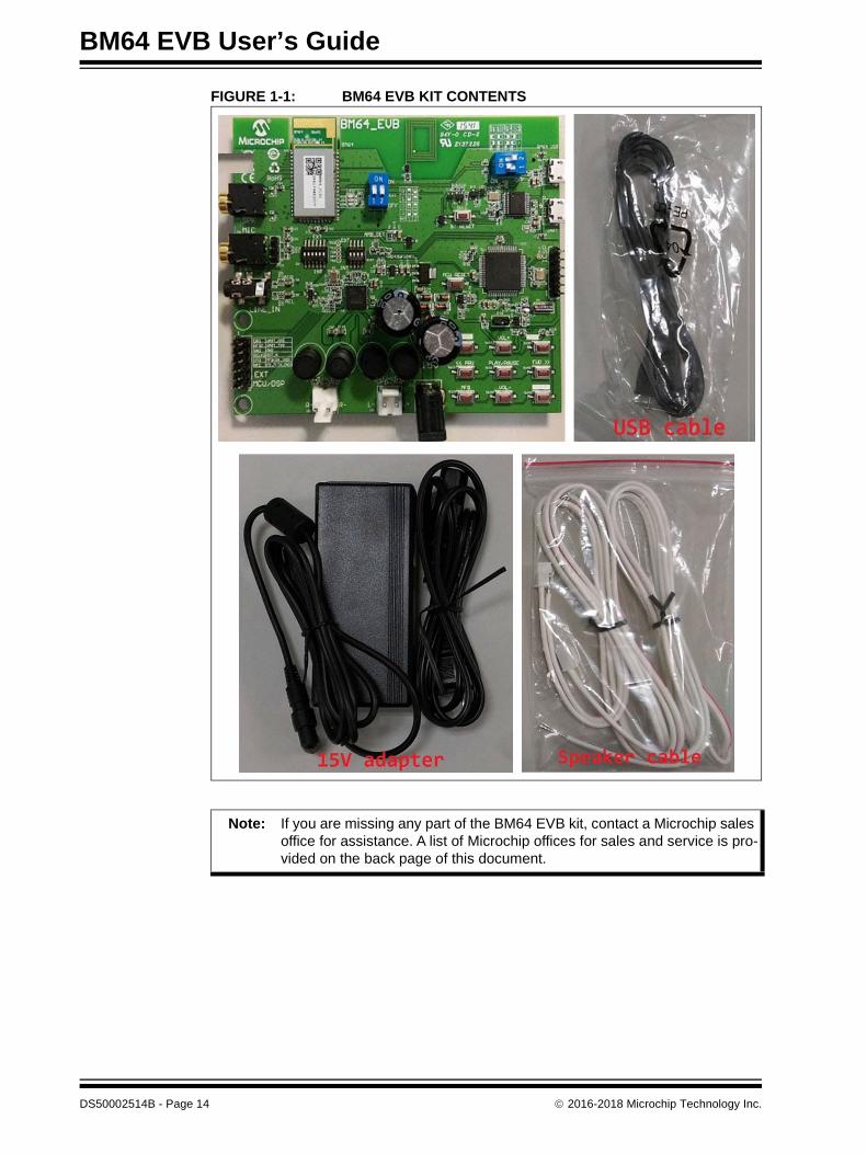
The BM64 EVB kit includes the following items, as illustrated in Figure 1-1:
• One BM64 EVB, which contains the BM64SPKS1MC1 module
• One micro-USB cable
• One 15V DC power adapter
• Two speaker cables
2016-2018 Microchip Technology Inc. DS50002514B - Page 13
BM64 EVB User’s Guide
FIGURE 1-1: BM64 EVB KIT CONTENTS
Note: If you are missing any part of the BM64 EVB kit, contact a Microchip sales office for assistance. A list of Microchip offices for sales and service is pro-vided on the back page of this document.
DS50002514B - Page 14 2016-2018 Microchip Technology Inc.
Introduction
1.2 BM64 EVB FEATURES
The following are key features of the BM64 EVB:
• The BM64 EVB includes a BM64 module, qualified for Bluetooth 4.2 specifications
• On-board MCU (PIC18F85J10) and DSP (YDA174) for easy operation and feature demonstration
• On-board keypad matrix that is controlled by MCU, which makes it easy for playback control
• Built-in Near Field Communication (NFC)
• RoHS compliant
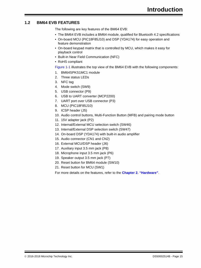
Figure 1-1 illustrates the top view of the BM64 EVB with the following components:
1. BM64SPKS1MC1 module
2. Three status LEDs
3. NFC tag
4. Mode switch (SW9)
5. USB connector (P9)
6. USB to UART converter (MCP2200)
7. UART port over USB connector (P3)
8. MCU (PIC18F85J10)
9. ICSP header (J5)
10. Audio control buttons, Multi-Function Button (MFB) and pairing mode button
11. 15V adapter jack (P2)
12. Internal/External MCU selection switch (SW46)
13. Internal/External DSP selection switch (SW47)
14. On-board DSP (YDA174) with built-in audio amplifier
15. Audio connector (CN1 and CN2)
16. External MCU/DSP header (J6)
17. Auxiliary input 3.5 mm jack (P8)
18. Microphone input 3.5 mm jack (P6)
19. Speaker output 3.5 mm jack (P7)
20. Reset button for BM64 module (SW10)
21. Reset button for MCU (SW1)
For more details on the features, refer to the Chapter 2. “Hardware”.
2016-2018 Microchip Technology Inc. DS50002514B - Page 15

BM64 EVB User’s Guide
FIGURE 1-1: BM64 EVB (TOP VIEW)
DS50002514B - Page 16 2016-2018 Microchip Technology Inc.
BM64 EVB USER’S GUIDE
Chapter 2. Hardware
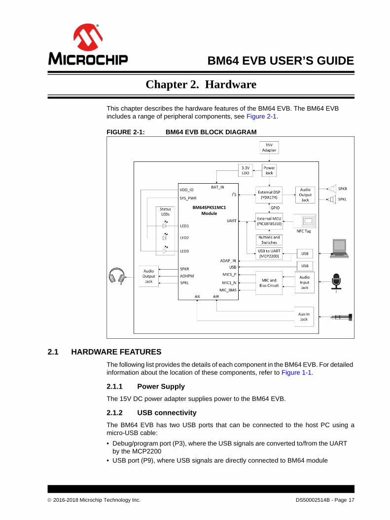
This chapter describes the hardware features of the BM64 EVB. The BM64 EVB includes a range of peripheral components, see Figure 2-1.
FIGURE 2-1: BM64 EVB BLOCK DIAGRAM
2.1 HARDWARE FEATURES
The following list provides the details of each component in the BM64 EVB. For detailed information about the location of these components, refer to Figure 1-1.
2.1.1 Power Supply
The 15V DC power adapter supplies power to the BM64 EVB.
2.1.2 USB connectivity
The BM64 EVB has two USB ports that can be connected to the host PC using amicro-USB cable:
• Debug/program port (P3), where the USB signals are converted to/from the UART by the MCP2200
• USB port (P9), where USB signals are directly connected to BM64 module
2016-2018 Microchip Technology Inc. DS50002514B - Page 17

BM64 EVB User’s Guide
2.1.3 Switches and Push Buttons
The functions of the switches and push buttons on the BM64 EVB are:
• SW1 – Reset button for the MCU
• SW9 – Mode switch
• SW10 – Reset button for BM64 module
• SW23 – Skip the audio track backward
• SW24 (MFB) – Push button to turn on/off the BM64 module
• SW27 – Increase volume
• SW28 – Decrease volume
• SW31 – Play or pause the audio playback
• SW40 – Button to enter into pairing mode
• SW45 – Skip the audio track forward
Table 2-1 provides the settings of Mode switch SW9 to configure the BM64 module in various operating modes.
TABLE 2-1: SWITCH SW9 DETAILS
Mode Switch Positions Pin Definition
Flash Test Mode 1: ON (P2_0: LOW)2: OFF (EAN: LOW)
Flash Application Mode 1: OFF (P2_0: HIGH)2: OFF (EAN: LOW)
ROM Test Mode 1: ON (P2_0: LOW)2: ON (EAN: HIGH)
ROM Application Mode 1: OFF (P2_0: HIGH)2: ON (EAN: HIGH)
DS50002514B - Page 18 2016-2018 Microchip Technology Inc.

Hardware
Table 2-2 details the signals and button connections of the SW46/SW47 switch to the BM64 module and the external MCU/DSP.
2.1.4 LEDs
The functions of three LEDs are listed as follows:
• LED1 – Indicates the Bluetooth connection status (UI configuration dependent)
• LED2 – Indicates the Bluetooth connection status (UI configuration dependent)
• LED3 – Charging indication LED (default setting is disabled)
TABLE 2-2: SWITCH SW46/SW47 DETAILS
Mode SW46/SW47 Switch position Pin Definition
On-board MCU (PIC18F85J10) and DSP audio amplifier (YDA174)signals connection to theBM64 module (default)
SW461: ON (NFC trigger to MCU)2: OFF (TXIND to MCU)3: ON (RST_N to MCU)4: ON (HCI_TXD to MCU)5: ON (HCI_RXD to MCU)6: ON (MFB controlled by MCU)SW471: ON (DT0 to DSP)2: ON (SCLK0 to DSP)3: ON (RFS0 to DSP)4: ON (NC)
External MCU and DSP audio amplifier connection
SW461: OFF (NFC trigger)2: OFF (TXIND)3: OFF (RST_N)4: OFF (HCI_TXD)5: OFF (HCI_RXD)6: OFF (MFB)SW471: OFF (DT0)2: OFF (SCLK0)3: OFF (RFS0)4: OFF (NC)
2016-2018 Microchip Technology Inc. DS50002514B - Page 19
BM64 EVB User’s Guide
2.1.5 Jumpers and Headers
The following jumpers and headers (J5, J6, JP23) are available on the BM64 EVB.
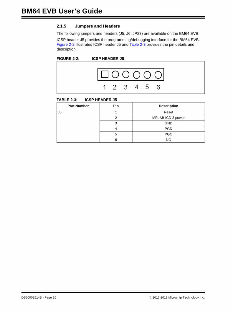
ICSP header J5 provides the programming/debugging interface for the BM64 EVB. Figure 2-2 illustrates ICSP header J5 and Table 2-3 provides the pin details and description.
FIGURE 2-2: ICSP HEADER J5
TABLE 2-3: ICSP HEADER J5
Part Number Pin Description
J5 1 Reset
2 MPLAB ICD 3 power
3 GND
4 PGD
5 PGC
6 NC
DS50002514B - Page 20 2016-2018 Microchip Technology Inc.

Hardware
The external MCU/DSP header J6 provides the interface to connect an external MCU/DSP to the BM64 EVB. Figure 2-3 illustrates external MCU/DSP header J6 and Table 2-4 provides the pin details and description.
FIGURE 2-3: EXTERNAL MCU/DSP HEADER J6
TABLE 2-4: EXTERNAL MCU/DSP HEADER J6
Part Number Pin Description
J6 1 I2S_DR
2 UART_RXD
3 I2S_RFS
4 UART_TXD
5 GND
6 GND
7 I2S_SCLK
8 RST_N
9 I2S_DT
10 RX_IND
11 NFC
12 TX_IND
2016-2018 Microchip Technology Inc. DS50002514B - Page 21
BM64 EVB User’s Guide
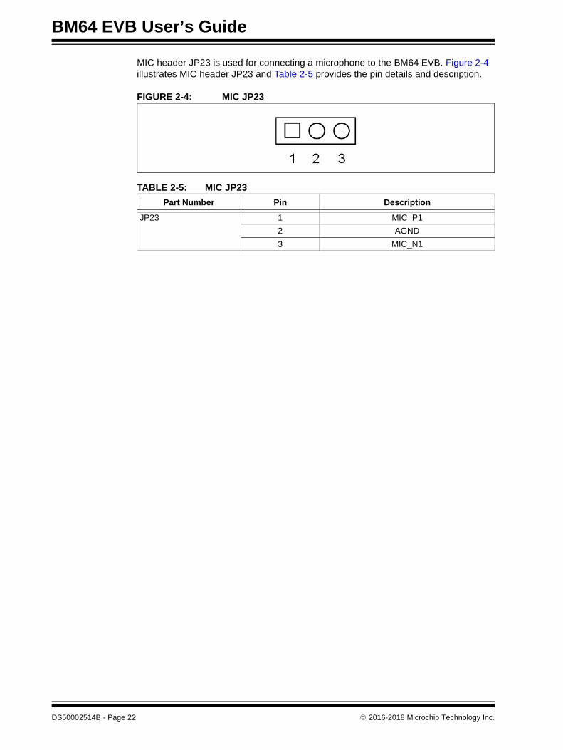
MIC header JP23 is used for connecting a microphone to the BM64 EVB. Figure 2-4 illustrates MIC header JP23 and Table 2-5 provides the pin details and description.
FIGURE 2-4: MIC JP23
TABLE 2-5: MIC JP23
Part Number Pin Description
JP23 1 MIC_P1
2 AGND
3 MIC_N1
DS50002514B - Page 22 2016-2018 Microchip Technology Inc.

BM64 EVB USER’S GUIDE
Chapter 3. Getting Started
This chapter describes how to establish Bluetooth connection between the BM64 EVB and a host device. It also demonstrates the process of updating the parameters using various tools.
This chapter includes the following topics:
3.1 “Requirements”
3.2 “Getting Started with BM64 EVB”
3.3 “Application Demonstration”
3.4 “Configuring BM64 Module”
3.5 “Updating EEPROM Parameters”
3.6 “Updating Flash Code”
3.7 “Updating MCU Parameters”
3.1 REQUIREMENTS
The following hardware and software components are required for getting started with the BM64 EVB.
3.1.1 Hardware Requirements
• BM64 EVB
• Bluetooth enabled smartphone:
- Android™ device running Android 4.3 or later version
- iOS: iPhone® 4S or later version
• Windows® host PC with USB port
• Speaker, microphone or headset
• Micro-USB cable
• MPLAB REAL ICE/MPLAB ICD 3/PICkit™ 3
3.1.2 Software Requirements
Download the latest firmware and corresponding tools from the Microchip web site at: www.microchip.com/BM64.
• User Interface tool
• DSP tool
• Mass Production EEPROM Tool (MPET)
• Firmware update tool
• Flash code
• EEPROM tool
• MPLAB® Integrated Development Environment (MPLAB X IDE) tool
Note: MPLAB X IDE is available for download from the Microchip web site at: www.microchip.com/mplab/mplab-x-ide.
2016-2018 Microchip Technology Inc. DS50002514B - Page 23

BM64 EVB User’s Guide
3.2 GETTING STARTED WITH BM64 EVB
The BM64 EVB is preprogrammed with dual-mode software where Advanced Audio Distribution Profile (A2DP) and Bluetooth Low Energy (BLE) can be operated simulta-neously. The MCU (PIC18F85J10, U13) on the BM64 EVB is also preprogrammed to work with dual-mode software. To establish the Bluetooth connection between the BM64 EVB and a host device, perform the following actions:
1. Set switch SW9 to Flash Application mode, see Figure 3-1.
FIGURE 3-1: SW9 IN FLASH APPLICATION MODE
2. Connect the speaker line to the amplifier output connector (CN1 and CN2).
3. Connect the 15V DC power adapter to P2, as illustrated in Figure 3-2.
FIGURE 3-2: USING THE EVALUATION BOARD
Note: Do not plug-in the USB cable.
DS50002514B - Page 24 2016-2018 Microchip Technology Inc.

Getting Started
4. Figure 3-3 illustrates the various push buttons on the BM64 EVB. Long press SW24 (MFB) (approximately 5 seconds) to turn the Bluetooth on. Both LED1 (blue) and LED2 (red) will blink together, and later only LED1 (blue) will blink once at regular intervals.
5. Long press SW40 (pairing key) to enter pairing mode (depending on the UART command settings from the MCU to the Bluetooth module). LED1 (blue) and LED2 (red) will blink alternatively to indicate that the BM64 EVB is in discoverable mode.
FIGURE 3-3: SW24 AND SW40
6. Turn on the Bluetooth on a host device (PC or smartphone) and it will display a list of discoverable Bluetooth devices. The BM64 EVB is displayed as “Dual_SPK” or “LE_Dual_SPK”. Select the device to establish the connection.
7. The LED1 (blue) blinks faster. This indicates the BM64 EVB is paired with the host device.
8. Once the connection is established, LED1 (blue) will blink twice at regular inter-vals. It will display as “connected” in the Bluetooth settings of the smartphone. With the default settings, the BM64 module enables Advanced Audio Distribution Profile (A2DP) for audio playback and Audio Video Remote Control Profile (AVRCP) for player control.
3.3 APPLICATION DEMONSTRATION
3.3.1 Audio Demonstration
In this demonstration, the user can stream audio on the BM64 EVB using a host device (PC or smartphone). Perform the following actions for the audio demonstration, refer to Figure 3-4.
1. Establish the connection between the BM64 EVB and a host device using the procedure listed in 3.2 “Getting Started with BM64 EVB”.
2. Once the connection between the BM64 EVB and the host device is established, open the audio source on the host device. Microchip recommends using a media player (for example: Windows® Media Player, iTunes®, and Android™).
Note: The “Dual_SPK” is used for the Bluetooth classic, and the “LE_Dual_SPK” is used for the BLE devices.
2016-2018 Microchip Technology Inc. DS50002514B - Page 25

BM64 EVB User’s Guide
3. Start the audio stream on the media player. Both LED1 (blue) and LED2 (red) will blink once at regular intervals during the audio playback.The audio control buttons are used for these functions:
- To control the audio output volume (long press VOL+ or VOL- button)
- Go to the previous track (short press << PRV button)
- Go to the next track (short press FWD >> button)
- Start/stop playing the current track (short press PLAY/PAUSE button)
FIGURE 3-4: BM64 EVB AUDIO CONTROL BUTTONS
3.3.2 HSP/HFP Demonstration
In this demonstration, the user can explore the Headset Profile (HSP) or Hands-Free Profile (HFP) setting to receive an incoming voice call from a paired smartphone. Per-form the following steps for demonstration, refer to Figure 3-4.
1. Establish the connection between the BM64 EVB and a host device using the procedure listed in 3.2 “Getting Started with BM64 EVB”.
2. Connect the speaker to the audio out connector (CN1 and CN2) and a micro-phone to the MIC input (P6), respectively, on the BM64 EVB.
3. Initiate a call from another phone to the smartphone that is paired with the BM64 EVB. The A2DP stream pauses and the ringtone is played on the speaker. LED1 (blue) blinks three times at regular intervals.
4. Press the SW24 (MFB) button on the BM64 EVB to accept the incoming call. LED1 (blue) and LED2 (red) will blink three times at regular intervals.
DS50002514B - Page 26 2016-2018 Microchip Technology Inc.

Getting Started
3.4 CONFIGURING BM64 MODULE
The BM64 EVB can be configured and various parameters can be customized using the UI tool and DSP tool, and then parameters are saved in a file. Using the MPET tool, the saved files are merged into the *.ipf file, and then this merged file is programmed into the EEPROM. After EEPROM is programmed, restart the device to see the effect of the customized parameters.
3.4.1 UI Tool Configuration
The User Interface (UI) tool is a configuration tool which enables the user to change the BM64 module parameters, such as device name, enable/disable pairing mode, BLE connection settings, configure the LEDs and enable/disable battery functions.
To configure the UI parameters, perform the following actions:
1. Open the UI configuration tool and click OK to configure the UI parameters, see Figure 3-5.
FIGURE 3-5: UI TOOL
Note: Download and install the UI tool, which is available on the Microchip web site: www.microchip.com/BM64. For this demonstration UITool_IS206x_012_DualModeSPK1.1_v1.03 is used.
2016-2018 Microchip Technology Inc. DS50002514B - Page 27

BM64 EVB User’s Guide
2. In the UI configuration tool, click Load, see Figure 3-6.
FIGURE 3-6: UI CONFIGURATION TOOL
DS50002514B - Page 28 2016-2018 Microchip Technology Inc.
Getting Started
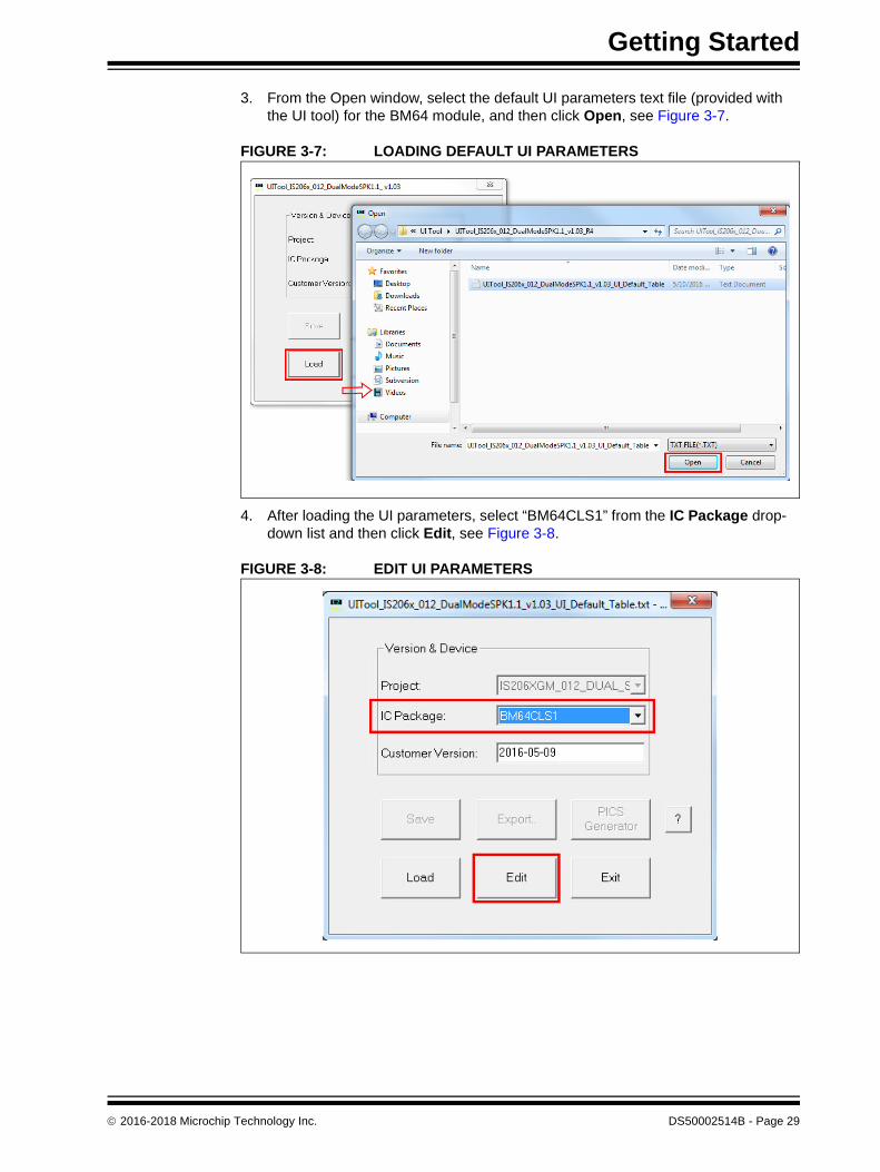
3. From the Open window, select the default UI parameters text file (provided with the UI tool) for the BM64 module, and then click Open, see Figure 3-7.
FIGURE 3-7: LOADING DEFAULT UI PARAMETERS
4. After loading the UI parameters, select “BM64CLS1” from the IC Package drop-down list and then click Edit, see Figure 3-8.
FIGURE 3-8: EDIT UI PARAMETERS
2016-2018 Microchip Technology Inc. DS50002514B - Page 29

BM64 EVB User’s Guide
5. In the Main Feature dialog, the user can enable or disable the Supported Profile and audio line-in function Button and set the following parameters, as illustrated in Figure 3-9.
a) Select the “UART Command” check box, which allows the module to be controlled by the MCU through the UART interface.
b) Select “I2S” check box for the volume key to function.
c) Select the “Ind.1” check box to enable the external audio amplifier.
d) Click Next.
FIGURE 3-9: MAIN FEATURE SETTINGS
DS50002514B - Page 30 2016-2018 Microchip Technology Inc.

Getting Started
6. The System and Functional Settings dialog with various options (tabs) is dis-played to configure the parameters. In the Sys. Setup2 tab, from the Indication 1 Setting section, enable External Amplifier Indication, as illustrated in Figure 3-10. Click Help to get more detailed information.
FIGURE 3-10: ENABLE EXTERNAL AMPLIFIER INDICATION
2016-2018 Microchip Technology Inc. DS50002514B - Page 31
BM64 EVB User’s Guide
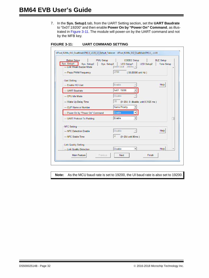
7. In the Sys. Setup1 tab, from the UART Setting section, set the UART Baudrate to “0x07:19200” and then enable Power On by “Power On” Command, as illus-trated in Figure 3-11. The module will power-on by the UART command and not by the MFB key.
FIGURE 3-11: UART COMMAND SETTING
Note: As the MCU baud rate is set to 19200, the UI baud rate is also set to 19200.
DS50002514B - Page 32 2016-2018 Microchip Technology Inc.
Getting Started
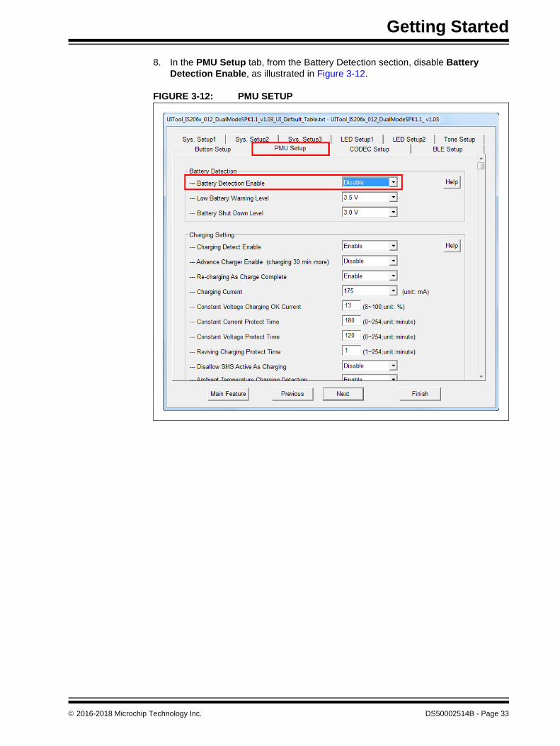
8. In the PMU Setup tab, from the Battery Detection section, disable Battery Detection Enable, as illustrated in Figure 3-12.
FIGURE 3-12: PMU SETUP
2016-2018 Microchip Technology Inc. DS50002514B - Page 33
BM64 EVB User’s Guide
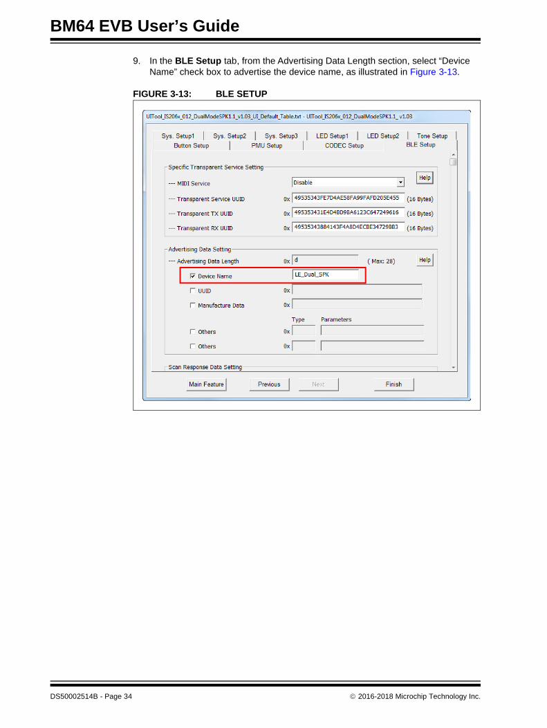
9. In the BLE Setup tab, from the Advertising Data Length section, select “Device Name” check box to advertise the device name, as illustrated in Figure 3-13.
FIGURE 3-13: BLE SETUP
DS50002514B - Page 34 2016-2018 Microchip Technology Inc.
Getting Started
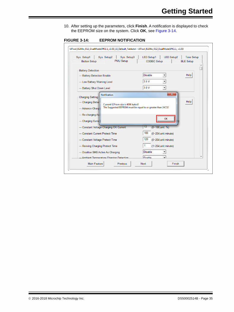
10. After setting up the parameters, click Finish. A notification is displayed to check the EEPROM size on the system. Click OK, see Figure 3-14.
FIGURE 3-14: EEPROM NOTIFICATION
2016-2018 Microchip Technology Inc. DS50002514B - Page 35

BM64 EVB User’s Guide
11. Click Save to save these UI parameters as a .txt file, see Figure 3-15.
FIGURE 3-15: SAVING UI PARAMETERS
12. From the Save As window, select the file location, and then click Save, see Figure 3-16.
FIGURE 3-16: SAVE AS WINDOW
13. After saving the UI parameters, click Exit.
DS50002514B - Page 36 2016-2018 Microchip Technology Inc.
Getting Started
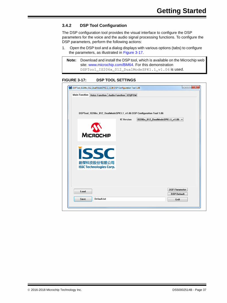
3.4.2 DSP Tool Configuration
The DSP configuration tool provides the visual interface to configure the DSP parameters for the voice and the audio signal processing functions. To configure the DSP parameters, perform the following actions:
1. Open the DSP tool and a dialog displays with various options (tabs) to configure the parameters, as illustrated in Figure 3-17.
FIGURE 3-17: DSP TOOL SETTINGS
Note: Download and install the DSP tool, which is available on the Microchip web site: www.microchip.com/BM64. For this demonstration DSPTool_IS206x_012_DualModeSPK1.1_v1.06 is used.
2016-2018 Microchip Technology Inc. DS50002514B - Page 37

BM64 EVB User’s Guide
2. In the Voice Function tab, set the parameters as illustrated in Figure 3-18.
FIGURE 3-18: DSP VOICE FUNCTION SETTING
DS50002514B - Page 38 2016-2018 Microchip Technology Inc.

Getting Started
3. In the Audio Function tab, set the parameters as illustrated in Figure 3-19.
FIGURE 3-19: DSP AUDIO FUNCTION SETTING
2016-2018 Microchip Technology Inc. DS50002514B - Page 39

BM64 EVB User’s Guide
4. Click Save to save these DSP parameters as .txt file, see Figure 3-20.
FIGURE 3-20: SAVING DSP PARAMETERS
DS50002514B - Page 40 2016-2018 Microchip Technology Inc.
Getting Started
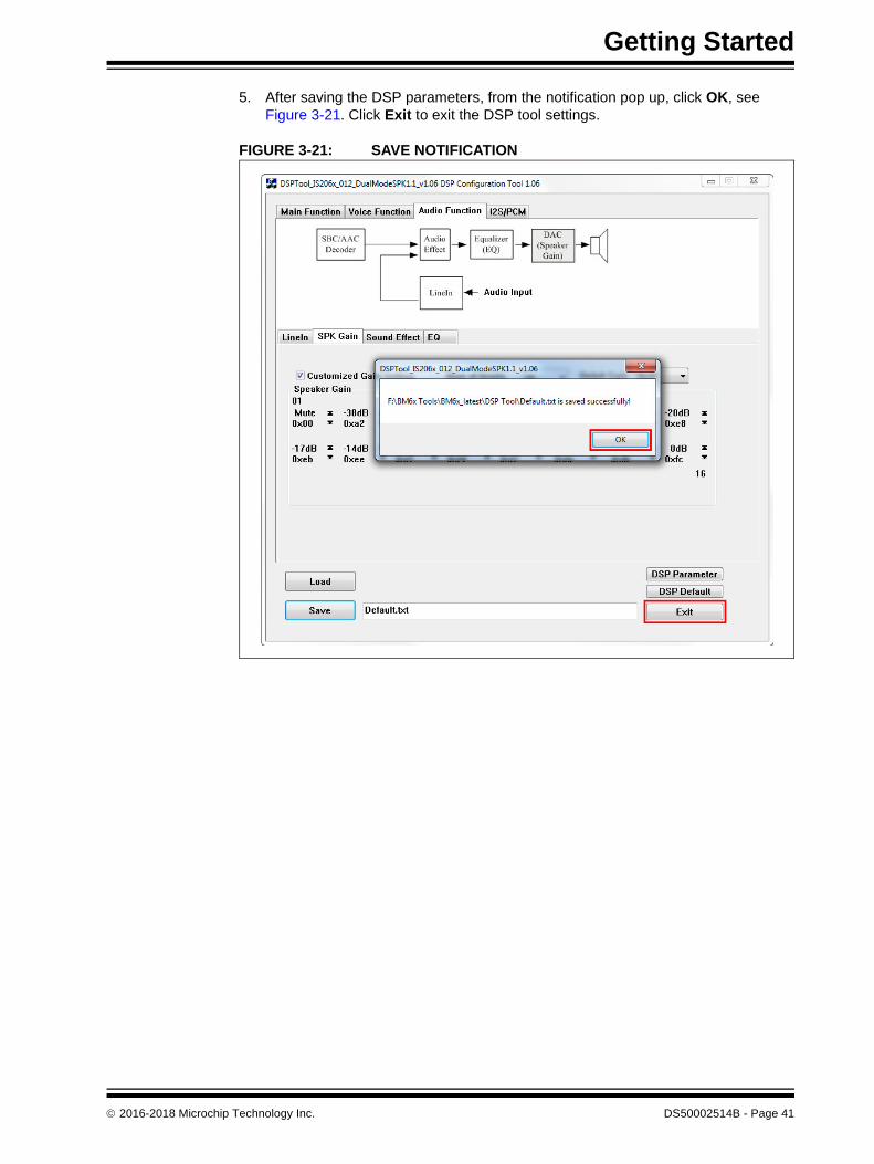
5. After saving the DSP parameters, from the notification pop up, click OK, see Figure 3-21. Click Exit to exit the DSP tool settings.
FIGURE 3-21: SAVE NOTIFICATION
2016-2018 Microchip Technology Inc. DS50002514B - Page 41

BM64 EVB User’s Guide
3.4.3 MPET Tool Configuration
The MPET tool is used to merge the UI and the DSP parameters, and generate a patch file (.ipf) or binary file (.bin). To generate a patch file using the MPET tool, perform the following actions:
1. Open the MPET tool and then click Next to continue with the configuration settings, see Figure 3-22.
FIGURE 3-22: MPET TOOL SETTING
Note: Download and install the MPET tool, which is available on the Microchip web site: www.microchip.com/BM64. For this demonstration MPET_V2.1.29.4804 is used.
DS50002514B - Page 42 2016-2018 Microchip Technology Inc.
Getting Started
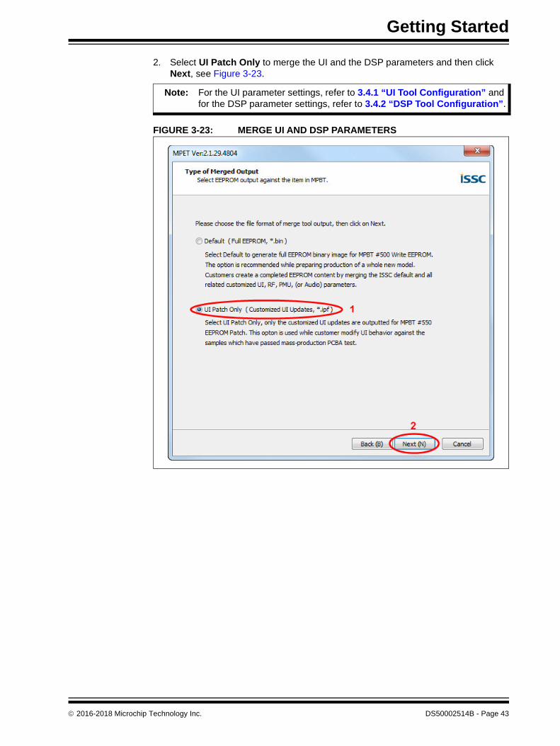
2. Select UI Patch Only to merge the UI and the DSP parameters and then click Next, see Figure 3-23.
FIGURE 3-23: MERGE UI AND DSP PARAMETERS
Note: For the UI parameter settings, refer to 3.4.1 “UI Tool Configuration” and for the DSP parameter settings, refer to 3.4.2 “DSP Tool Configuration”.
2016-2018 Microchip Technology Inc. DS50002514B - Page 43
BM64 EVB User’s Guide
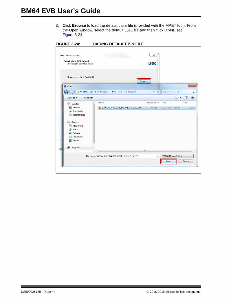
3. Click Browse to load the default .bin file (provided with the MPET tool). From the Open window, select the default .bin file and then click Open, see Figure 3-24.
FIGURE 3-24: LOADING DEFAULT BIN FILE
DS50002514B - Page 44 2016-2018 Microchip Technology Inc.

Getting Started
4. The bin file description is displayed. Click Next, see Figure 3-25.
FIGURE 3-25: DEFAULT BIN FILE SETTING
2016-2018 Microchip Technology Inc. DS50002514B - Page 45
BM64 EVB User’s Guide
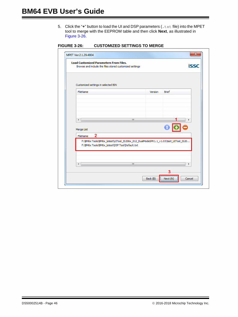
5. Click the “+” button to load the UI and DSP parameters (.txt file) into the MPET tool to merge with the EEPROM table and then click Next, as illustrated in Figure 3-26.
FIGURE 3-26: CUSTOMIZED SETTINGS TO MERGE
DS50002514B - Page 46 2016-2018 Microchip Technology Inc.

Getting Started
6. Select an Output File path to create the merged EEPROM table (.ipf file) and then click Next, see Figure 3-27.
FIGURE 3-27: SELECTING OUTPUT FILE NAME AND PATH
2016-2018 Microchip Technology Inc. DS50002514B - Page 47

BM64 EVB User’s Guide
7. Click Generate to generate the EEPROM table (.ipf file), see Figure 3-28.
FIGURE 3-28: GENERATE EEPROM TABLE
DS50002514B - Page 48 2016-2018 Microchip Technology Inc.

Getting Started
8. The calibration parameters included in the UI patch file can be selected or ignored. Click Next, see Figure 3-29.
FIGURE 3-29: CALIBRATION PARAMETERS CHECK
Note: If the items are selected, the calibration parameters of the .ipf file will overwrite the parameters in the device.
2016-2018 Microchip Technology Inc. DS50002514B - Page 49

BM64 EVB User’s Guide
9. After generating the merged EEPROM table (.ipf file), click Finish to exit the wizard, see Figure 3-30.
FIGURE 3-30: GENERATED OUTPUT FILE
3.5 UPDATING EEPROM PARAMETERS
The EEPROM tool is used to write the EEPROM parameters in the BM64 module. Perform the following actions to update the EEPROM parameters:
1. Set switch SW9 to Flash Test mode, see Figure 3-31.
FIGURE 3-31: SWITCH SW9 IN FLASH TEST MODE
2. Connect the BM64 UART Connector (P3) port to a host PC using a micro-USB cable, as illustrated in Figure 3-32. The default LED behavior in Flash Test mode is: LED1 (blue) and LED2 (red) will be ON.
DS50002514B - Page 50 2016-2018 Microchip Technology Inc.

Getting Started
FIGURE 3-32: EEPROM PARAMETERS SETUP
Note: Download and install the EEPROM tool, which is available on the Microchip web site: www.microchip.com/BM64. For this demonstration EEPROM_Tool_V2.1.29.4800 is used.
2016-2018 Microchip Technology Inc. DS50002514B - Page 51

BM64 EVB User’s Guide
3. Open the EEPROM tool and a window displays, see Figure 3-33.
FIGURE 3-33: EEPROM TOOL
DS50002514B - Page 52 2016-2018 Microchip Technology Inc.

Getting Started
4. Specify the COM Port and click IC/Module identity, see Figure 3-34.
FIGURE 3-34: EEPROM TOOL SETTINGS
2016-2018 Microchip Technology Inc. DS50002514B - Page 53
BM64 EVB User’s Guide
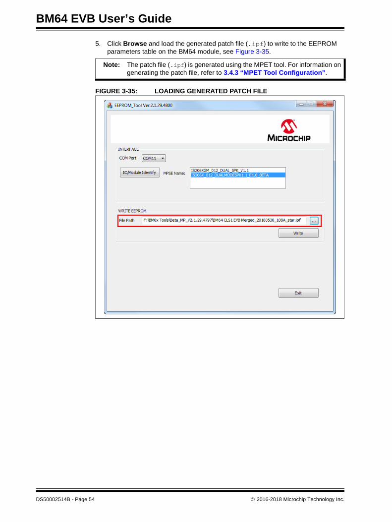
5. Click Browse and load the generated patch file (.ipf) to write to the EEPROM parameters table on the BM64 module, see Figure 3-35.
FIGURE 3-35: LOADING GENERATED PATCH FILE
Note: The patch file (.ipf) is generated using the MPET tool. For information on generating the patch file, refer to 3.4.3 “MPET Tool Configuration”.
DS50002514B - Page 54 2016-2018 Microchip Technology Inc.

Getting Started
6. Click Write to program the EEPROM parameters on the BM64 module. After programming the EEPROM parameters, a message is displayed. Click OK as illustrated in Figure 3-36.
FIGURE 3-36: WRITE EEPROM
7. Click Exit and remove the micro-USB cable. Then, set SW9 to Flash Application mode (see Figure 3-37) and reboot.
FIGURE 3-37: SWITCH SW9 IN FLASH APPLICATION MODE
2016-2018 Microchip Technology Inc. DS50002514B - Page 55

BM64 EVB User’s Guide
3.6 UPDATING FLASH CODE
A new or a specific version of the flash code can be programmed using the Flash Pro-gramming tool. To program the Flash code, perform these actions:
1. Set switch SW9 to ROM Test mode, see Figure 3-38.
FIGURE 3-38: SWITCH SW9 IN ROM TEST MODE
2. Connect the BM64 UART connector (P3) port to a host PC using a micro-USB cable, as illustrated in Figure 3-39. The default LED behavior in ROM Test mode is: LED1 (blue) and LED2 (red) will be ON.
FIGURE 3-39: FLASH CODE SETUP
Note: Download and install the isupdate.exe firmware update tool, which is available on the Microchip web site: www.microchip.com/BM64. For this demonstration, flash code DUAL_SPK_FIRMWARE_V1.1 is used.
DS50002514B - Page 56 2016-2018 Microchip Technology Inc.

Getting Started
3. Open the isupdate.exe firmware update tool on a host PC and a window is displayed, see Figure 3-40.
FIGURE 3-40: FIRMWARE UPDATE TOOL
2016-2018 Microchip Technology Inc. DS50002514B - Page 57
BM64 EVB User’s Guide
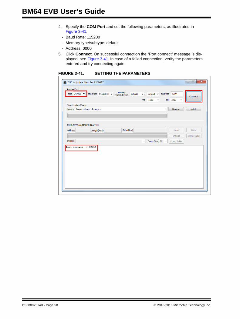
4. Specify the COM Port and set the following parameters, as illustrated in Figure 3-41.
- Baud Rate: 115200
- Memory type/subtype: default
- Address: 0000
5. Click Connect. On successful connection the “Port connect” message is dis-played, see Figure 3-41. In case of a failed connection, verify the parameters entered and try connecting again.
FIGURE 3-41: SETTING THE PARAMETERS
DS50002514B - Page 58 2016-2018 Microchip Technology Inc.

Getting Started
6. Click Browse to select the Flash code files (.hex) downloaded from the Microchip web site, see Figure 3-42.
FIGURE 3-42: LOADING FIRMWARE IMAGE
2016-2018 Microchip Technology Inc. DS50002514B - Page 59

BM64 EVB User’s Guide
7. From the Open window, select the Flash code files and click Open, see Figure 3-43.
FIGURE 3-43: SELECTING FLASH CODE FILES
DS50002514B - Page 60 2016-2018 Microchip Technology Inc.
Getting Started
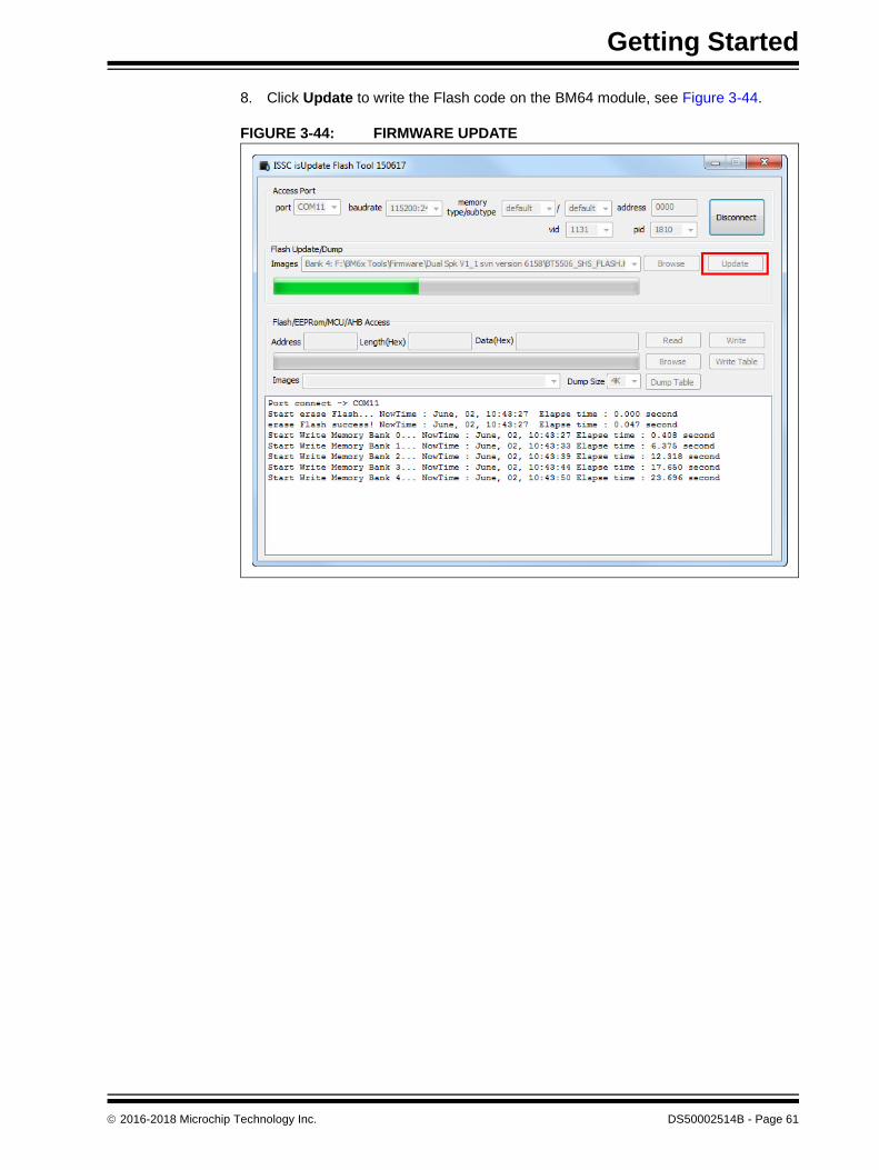
8. Click Update to write the Flash code on the BM64 module, see Figure 3-44.
FIGURE 3-44: FIRMWARE UPDATE
2016-2018 Microchip Technology Inc. DS50002514B - Page 61

BM64 EVB User’s Guide
9. The Firmware Update tool will start writing the Flash codes. Wait until the mes-sage “End of Write Memory!” with the elapse time is displayed, see Figure 3-45.
FIGURE 3-45: WRITING FLASH CODE
DS50002514B - Page 62 2016-2018 Microchip Technology Inc.

Getting Started
10. After the Flash code update, click Disconnect, see Figure 3-45. The “port dis-connect” message is displayed, see Figure 3-46. Then remove the USB cable to reboot.
FIGURE 3-46: FIRMWARE UPDATE FINISH
2016-2018 Microchip Technology Inc. DS50002514B - Page 63
BM64 EVB User’s Guide
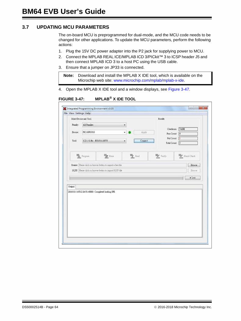
3.7 UPDATING MCU PARAMETERS
The on-board MCU is preprogrammed for dual-mode, and the MCU code needs to be changed for other applications. To update the MCU parameters, perform the following actions:
1. Plug the 15V DC power adapter into the P2 jack for supplying power to MCU.
2. Connect the MPLAB REAL ICE/MPLAB ICD 3/PICkit™ 3 to ICSP header J5 and then connect MPLAB ICD 3 to a host PC using the USB cable.
3. Ensure that a jumper on JP33 is connected.
4. Open the MPLAB X IDE tool and a window displays, see Figure 3-47.
FIGURE 3-47: MPLAB® X IDE TOOL
Note: Download and install the MPLAB X IDE tool, which is available on the Microchip web site: www.microchip.com/mplab/mplab-x-ide.
DS50002514B - Page 64 2016-2018 Microchip Technology Inc.
Getting Started
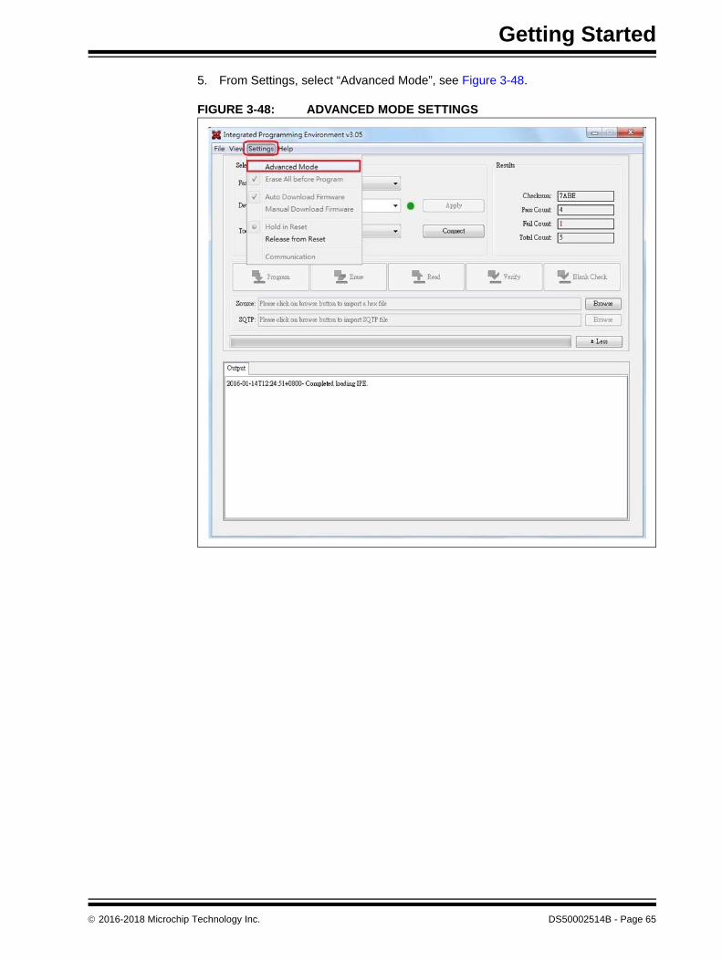
5. From Settings, select “Advanced Mode”, see Figure 3-48.
FIGURE 3-48: ADVANCED MODE SETTINGS
2016-2018 Microchip Technology Inc. DS50002514B - Page 65

BM64 EVB User’s Guide
6. The MPLAB X IDE tool will display a window with various options (tabs) to con-figure the parameters. Click the Power tab, and then enable Power Target Cur-rent from Tool, as illustrated in Figure 3-49.
FIGURE 3-49: POWER TARGET CURRENT FROM TOOL
DS50002514B - Page 66 2016-2018 Microchip Technology Inc.
Getting Started
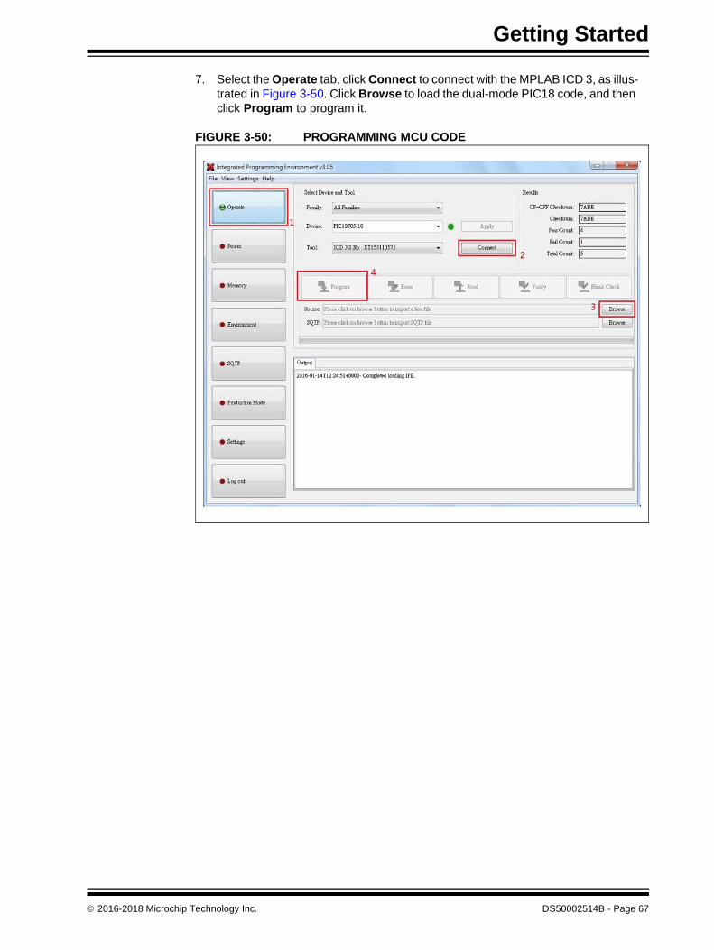
7. Select the Operate tab, click Connect to connect with the MPLAB ICD 3, as illus-trated in Figure 3-50. Click Browse to load the dual-mode PIC18 code, and then click Program to program it.
FIGURE 3-50: PROGRAMMING MCU CODE
2016-2018 Microchip Technology Inc. DS50002514B - Page 67

BM64 EVB User’s Guide
NOTES:
DS50002514B - Page 68 2016-2018 Microchip Technology Inc.

BM64 EVB USER’S GUIDE
Appendix A. Schematics
A.1 REFERENCE SCHEMATICS
FIGURE A-1: BM64 EVB SCHEMATICS
2016-2018 Microchip Technology Inc. DS50002514B - Page 69
BM
64 EV
B U
ser’s Gu
ide
DS
50
00
25
14
B - P
ag
e 7
0
20
16
-20
18
Micro
chip
Te
chn
olo
gy In
c.
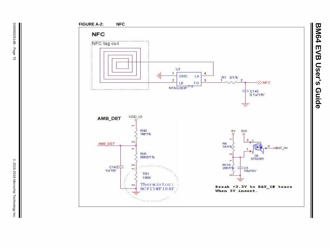
FIGURE A-2: NFC
Schematics
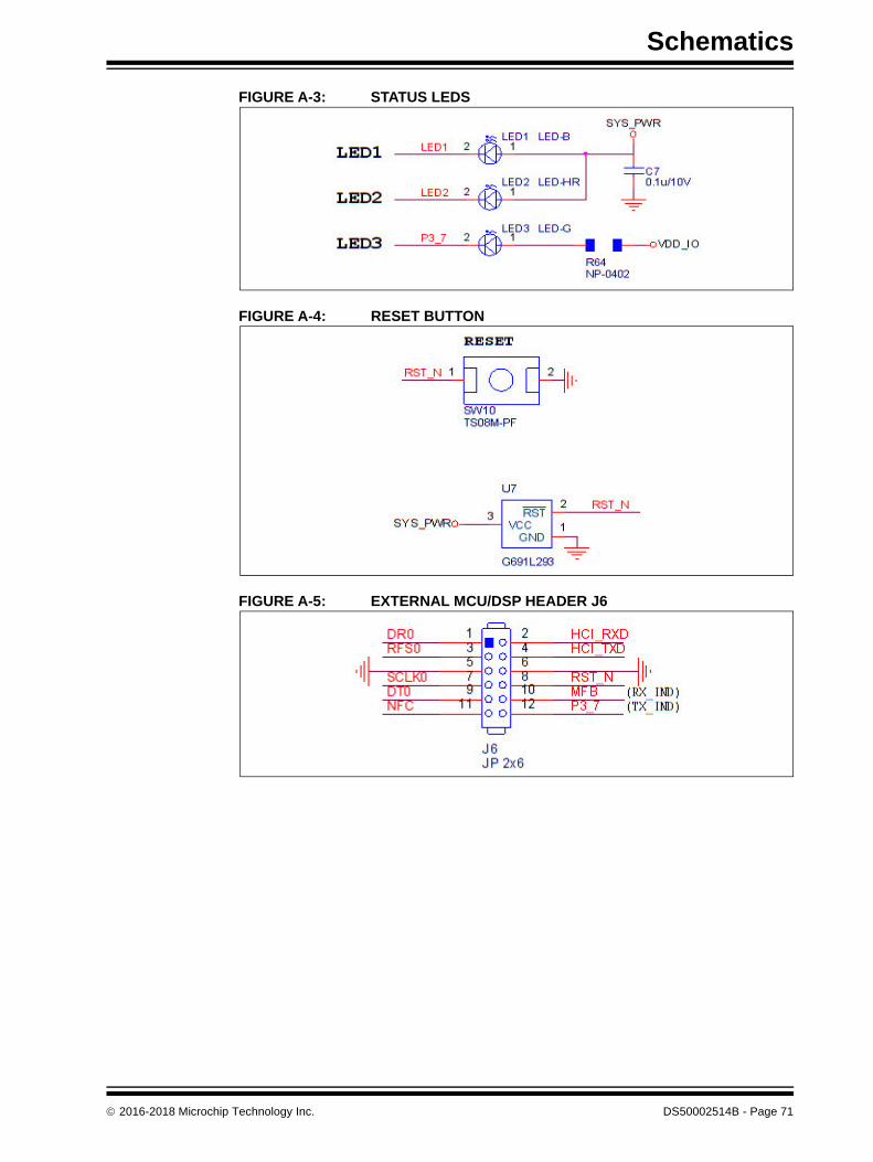
FIGURE A-3: STATUS LEDS
FIGURE A-4: RESET BUTTON
FIGURE A-5: EXTERNAL MCU/DSP HEADER J6
2016-2018 Microchip Technology Inc. DS50002514B - Page 71
BM64 EVB User’s Guide
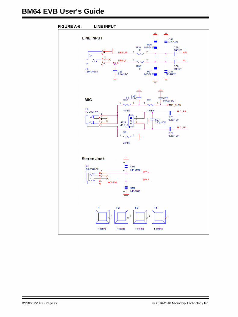
FIGURE A-6: LINE INPUT
DS50002514B - Page 72 2016-2018 Microchip Technology Inc.
Sch
ematics
2
01
6-2
01
8 M
icroch
ip T
ech
no
log
y Inc.
DS
50
00
25
14
B - P
ag
e 7
3
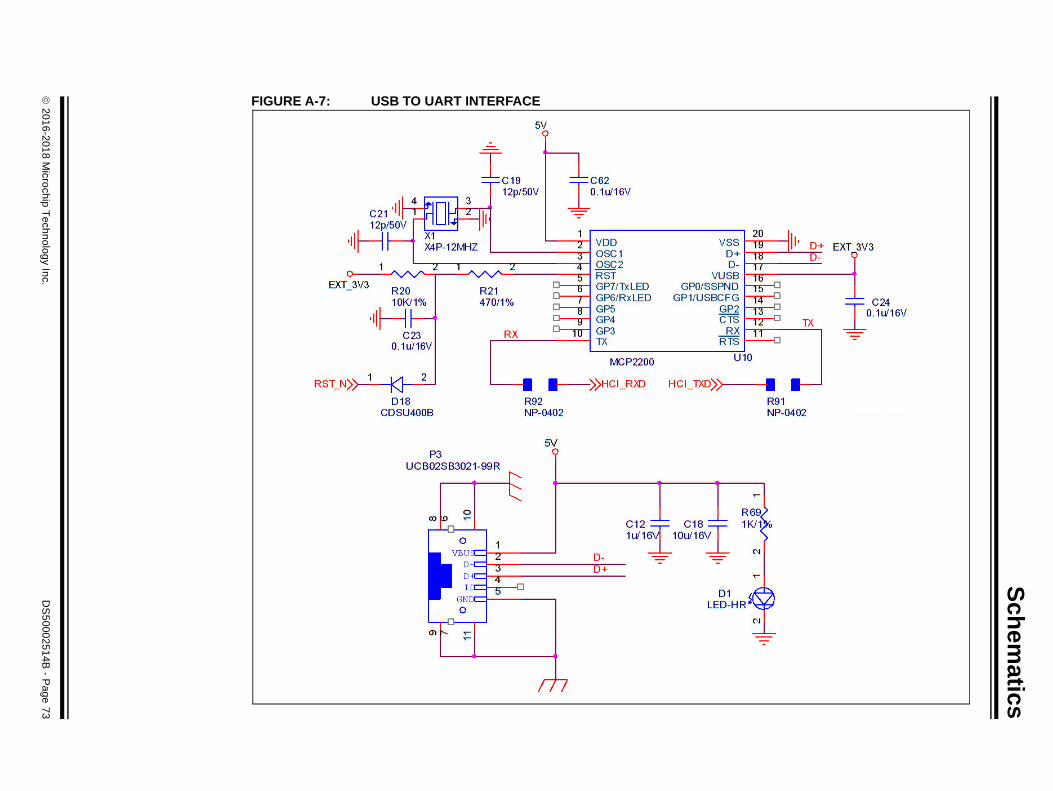
FIGURE A-7: USB TO UART INTERFACE

BM64 EVB User’s Guide
FIGURE A-8: UART INTERFACE
DS50002514B - Page 74 2016-2018 Microchip Technology Inc.

Schematics
FIGURE A-9: SWITCH CONFIGURATION
2016-2018 Microchip Technology Inc. DS50002514B - Page 75

BM
64 EV
B U
ser’s Gu
ide
DS
50
00
25
14
B - P
ag
e 7
6
20
16
-20
18
Micro
chip
Te
chn
olo
gy In
c.
FIGURE A-10: DSP SCHEMATICS
Schematics
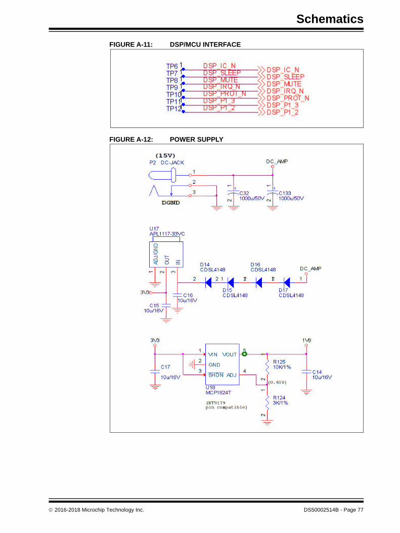
FIGURE A-11: DSP/MCU INTERFACE
FIGURE A-12: POWER SUPPLY
2016-2018 Microchip Technology Inc. DS50002514B - Page 77
BM64 EVB User’s Guide
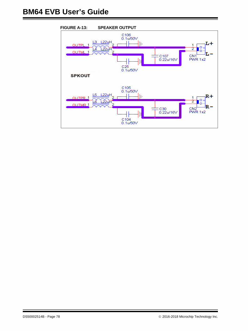
FIGURE A-13: SPEAKER OUTPUT
DS50002514B - Page 78 2016-2018 Microchip Technology Inc.

Sch
ematics
2
01
6-2
01
8 M
icroch
ip T
ech
no
log
y Inc.
DS
50
00
25
14
B - P
ag
e 7
9
FIGURE A-14: EXTERNAL MCU INTERFACE

BM64 EVB User’s Guide
FIGURE A-15: SWITCH SW46/SW47 CONFIGURATION
FIGURE A-16: ICSP
DS50002514B - Page 80 2016-2018 Microchip Technology Inc.
Schematics
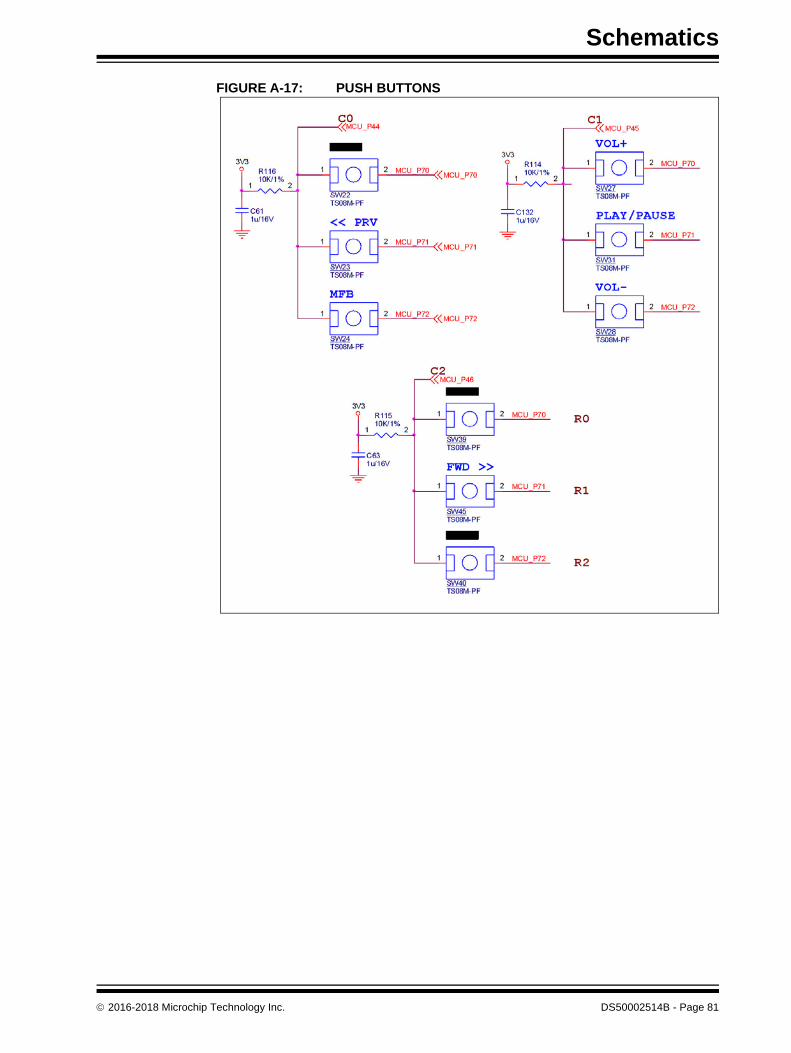
FIGURE A-17: PUSH BUTTONS
2016-2018 Microchip Technology Inc. DS50002514B - Page 81

BM64 EVB User’s Guide
NOTES:
DS50002514B - Page 82 2016-2018 Microchip Technology Inc.

2016-2018 Microchip Technology Inc. DS50002514B - Page 83
NOTES:

DS50002514B-page 84 2016-2018 Microchip Technology Inc.
AMERICASCorporate Office2355 West Chandler Blvd.Chandler, AZ 85224-6199Tel: 480-792-7200 Fax: 480-792-7277Technical Support: http://www.microchip.com/supportWeb Address: www.microchip.com
AtlantaDuluth, GA Tel: 678-957-9614 Fax: 678-957-1455
Austin, TXTel: 512-257-3370
BostonWestborough, MA Tel: 774-760-0087 Fax: 774-760-0088
ChicagoItasca, IL Tel: 630-285-0071 Fax: 630-285-0075
DallasAddison, TX Tel: 972-818-7423 Fax: 972-818-2924
DetroitNovi, MI Tel: 248-848-4000
Houston, TX Tel: 281-894-5983
IndianapolisNoblesville, IN Tel: 317-773-8323Fax: 317-773-5453Tel: 317-536-2380
Los AngelesMission Viejo, CA Tel: 949-462-9523Fax: 949-462-9608Tel: 951-273-7800
Raleigh, NC Tel: 919-844-7510
New York, NY Tel: 631-435-6000
San Jose, CA Tel: 408-735-9110Tel: 408-436-4270
Canada - TorontoTel: 905-695-1980 Fax: 905-695-2078
ASIA/PACIFICAustralia - SydneyTel: 61-2-9868-6733
China - BeijingTel: 86-10-8569-7000
China - ChengduTel: 86-28-8665-5511
China - ChongqingTel: 86-23-8980-9588
China - DongguanTel: 86-769-8702-9880
China - GuangzhouTel: 86-20-8755-8029
China - HangzhouTel: 86-571-8792-8115
China - Hong Kong SARTel: 852-2943-5100
China - NanjingTel: 86-25-8473-2460
China - QingdaoTel: 86-532-8502-7355
China - ShanghaiTel: 86-21-3326-8000
China - ShenyangTel: 86-24-2334-2829
China - ShenzhenTel: 86-755-8864-2200
China - SuzhouTel: 86-186-6233-1526
China - WuhanTel: 86-27-5980-5300
China - XianTel: 86-29-8833-7252
China - XiamenTel: 86-592-2388138
China - ZhuhaiTel: 86-756-3210040
ASIA/PACIFICIndia - BangaloreTel: 91-80-3090-4444
India - New DelhiTel: 91-11-4160-8631
India - PuneTel: 91-20-4121-0141
Japan - OsakaTel: 81-6-6152-7160
Japan - TokyoTel: 81-3-6880- 3770
Korea - DaeguTel: 82-53-744-4301
Korea - SeoulTel: 82-2-554-7200
Malaysia - Kuala LumpurTel: 60-3-7651-7906
Malaysia - PenangTel: 60-4-227-8870
Philippines - ManilaTel: 63-2-634-9065
SingaporeTel: 65-6334-8870
Taiwan - Hsin ChuTel: 886-3-577-8366
Taiwan - KaohsiungTel: 886-7-213-7830
Taiwan - TaipeiTel: 886-2-2508-8600
Thailand - BangkokTel: 66-2-694-1351
Vietnam - Ho Chi MinhTel: 84-28-5448-2100
EUROPEAustria - WelsTel: 43-7242-2244-39Fax: 43-7242-2244-393
Denmark - CopenhagenTel: 45-4450-2828 Fax: 45-4485-2829
Finland - EspooTel: 358-9-4520-820
France - ParisTel: 33-1-69-53-63-20 Fax: 33-1-69-30-90-79
Germany - GarchingTel: 49-8931-9700
Germany - HaanTel: 49-2129-3766400
Germany - HeilbronnTel: 49-7131-67-3636
Germany - KarlsruheTel: 49-721-625370
Germany - MunichTel: 49-89-627-144-0 Fax: 49-89-627-144-44
Germany - RosenheimTel: 49-8031-354-560
Israel - Ra’anana Tel: 972-9-744-7705
Italy - Milan Tel: 39-0331-742611 Fax: 39-0331-466781
Italy - PadovaTel: 39-049-7625286
Netherlands - DrunenTel: 31-416-690399 Fax: 31-416-690340
Norway - TrondheimTel: 47-7289-7561
Poland - WarsawTel: 48-22-3325737
Romania - BucharestTel: 40-21-407-87-50
Spain - MadridTel: 34-91-708-08-90Fax: 34-91-708-08-91
Sweden - GothenbergTel: 46-31-704-60-40
Sweden - StockholmTel: 46-8-5090-4654
UK - WokinghamTel: 44-118-921-5800Fax: 44-118-921-5820
Worldwide Sales and Service
10/25/17