Corset Deal India - An Authentic Corset Store for the Best in Overbust Corsets
Below-Knee Waterproof Sports Prosthesis with Joints and Corset by Alfred W. Lehneis, CP.
This article is concerned with the development of a waterproof below-knee prosthesis with knee joints and corset, utilizing the supracondylar/suprapatellar (SC/SP) suspension socket. A case report is described below.
The patient had a below-knee amputation due to traumatic injury with a resultant amputation length of the tibia of approximately 1" (Figure 1). This patient currently wears a PTB type socket with leather thigh corset, polycen-tric joints and an SC/SP suspension socket, thus, no auxilliary suspension was necessary (Figure 2). He was doing well with this design in all activities of daily living, but desired a waterproof prosthesis for boating.
In developing the waterproof design, the following components were utilized: Kingsley beachcomber foot, Otto Bock polycentric stainless steel knee joints, and a corset fabricated from 4mm Subortholen thermoplastic. Closures were 1" dacron straps with virgin nylon buckle closures used on scoliosis type body jackets.
The fitting and fabrication of the prosthesis was as follows: the patient was casted (including the thigh) and the cast modified, using standard procedures for SC/SP suspension, an insert was fabricated from Pelite®, and the socket was fabricated with acrylic resin and carbon/glass reinforcements, especially at the side bar attachment sites.
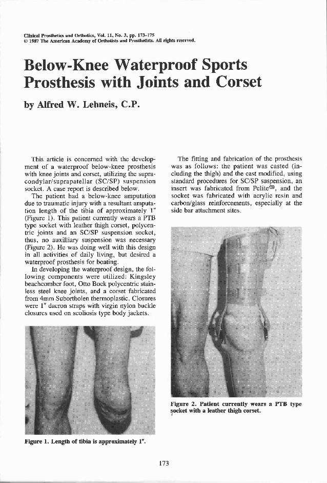
Figure 1. Length of tibia is approximately 1".
Figure 2. Patient currently wears a PTB type socket with a leather thigh corset.

Figure 3 . The laminated shell is split longitudinally on the posterior aspect.
After fabrication of the socket, the socket was foamed up and set-up on a Staros-Gardner coupling and aligned atop the beachcomber foot. The bars were then attached directly to the socket (not over the foam build-up), and the area over the bars filled with fiberglass/resin putty. The thigh bars were contoured to the modified cast, over which the Subortholen thermoplastic had been molded and attached to the corset. The patient was then fitted and aligned in the usual manner, but while wearing topsider type boating shoes.
After optimum alignment was achieved, the Staros/Gardener coupling was transferred out. This can be accomplished on a horizontal transfer device. The prosthesis was then shaped to the patient's tracing and measurements and reduced to accommodate the lamination thickness. The sole of the foot is then removed and a woman's nylon is pulled over the entire prosthesis, followed by the PVA sleeve. A lamination of one carbon-glass and two nylons without pigment is performed. After the lamination is set, the laminated shell is split longitudinally on the posterior aspect (Figure 3), taken off the prosthesis, and taped back together to retain its shape.
The shaped portion of the prosthesis is cut to allow for a 3" ankle block and the socket is cut at the base. The foam between the ankle and socket is now eliminated (Figure 3). The foam ankle block and the foam at the base of the socket can be sealed with a resin-silica mix to prevent water penetration.
The laminated shell should be sealed with tape on the outside, and the seam should be sealed on the inside with Siegelharz. The socket and ankle block can then be bonded to
the laminated shell. Once this is set, the outer shell should be sanded for a second lamination, and approximately 1" of the proximal socket and distal ankle block perimeter should be exposed (Figure 3).
The prosthesis is then filled with sand through the hole at the bottom of the ankle block. The hole is then sealed with play dough. Lay-up of the prosthesis consists of six alternating layers of nylon and nyglass. Two pieces of polypropylene with 120° arcs (Figure 3) should be placed between the joints and the socket after the first two layers to allow attachment of the joint clevis after lamination. These pieces are removed after lamination. The foot drain hole is then reopened to release the sand. A second 1/2" hole should be drilled posterior and distal to the socket end to allow air to enter and escape the inner hollow of the leg. This allows water to enter and escape the foot drain hole and prevent bouyancy of the prosthesis.
The thermoplastic corset is finished with a polyethylene tongue and dacron strap closures as described earlier. When assembling the prosthesis, bonding of the foot should be as recommended by Kingsley, Mfg. or using Devcon two-part epoxy.
Acknowledgments The author gratefully acknowledges the technical contri
bution of Roger Losee, C O . , and Robert Wilson, M.S. , for the illustration in Figure 3.
Author Alfred W. Lehneis, C P . , is with Lehneis Orthotics and
Prosthetics Associates in Roslyn, New York.