be damaged due to the explosion. Approvals from all ... N007-040-2014... · be damaged due to the...
100
NRA N007_040_2014_V3_B2_2.DOC 06 August 2015 C-121 be damaged due to the explosion. Approvals from all service owners shall be obtained by the contractor. The LORWUA canal and syphon is of particular concern and special precautions shall be taken to prevent damage to these structures. Notwithstanding any approvals and permissions given, the contractor shall remain responsible for any unintended damage due to blasting activities.” g) The safety of excavations Add the following paragraph: “The design for shoring, signing of the drawings and inspection prior to construction of the permanent works of excavations to ensure it is safe shall be undertaken by the contractor’s competent person, who shall be a professional engineer with the relevant experience. The contractor shall ensure that all temporary works undertaken shall comply with the relevant sections of the Occupational Health and Safety Act and the Construction Regulations”. B6106 FOUNDING Add the following clause at the end of the last paragraph: “Where foundation slabs or pile caps are cast directly against the face of the excavations, the volume of concrete measured for payment shall be the total volume of concrete placed or the volume based on the plan dimensions detailed on the drawings plus a 100mm allowance for overbreak on each applicable side whichever is the lesser. No formwork to the footing shall be measured when the concrete is cast against the face of the excavations”. B6109 FOUNDATION FILL In the 5th paragraph, 7th line delete “60” substitute “45”. Add the following after the 6th paragraph: “Concrete blinding shall extend 100mm all round beyond the horizontal dimensions of all formed footings to facilitate placing of the formwork, unless otherwise directed by the engineer. In the case of structures where excessive ground water is encountered, the blinding layer may extend over the full plan area of the base of the excavation and beyond the edge of the foundation where required. Payment shall be made for the quantity of concrete calculated as the product of the specified thickness of blinding layer and the actual area of blinding placed subject to a maximum distance of 500mm beyond the edge of the foundation.” B6113 FOUNDATION PILING u) Load test (vi) General Insert the following as a first paragraph at the beginning of this clause: “The engineer may require that a trial pile(s) be installed and load tested prior to the commencement of the piling works proper. The engineer may require that the installation of such trial pile(s) be measured and paid for separately, thus not forming part of the working piles installed later on.“ Insert the word “working“ between the words “selected“ and “piles” in the first sentence of the next paragraph. Insert the following after “subclause 8112 (c)“:
Transcript of be damaged due to the explosion. Approvals from all ... N007-040-2014... · be damaged due to the...

NRA N007_040_2014_V3_B2_2.DOC 06 August 2015
C-121
be damaged due to the explosion. Approvals from all service owners shall be obtained by the contractor. The LORWUA canal and syphon is of particular concern and special precautions shall be taken to prevent damage to these structures. Notwithstanding any approvals and permissions given, the contractor shall remain responsible for any unintended damage due to blasting activities.”
g) The safety of excavations
Add the following paragraph:
“The design for shoring, signing of the drawings and inspection prior to construction of the permanent works of excavations to ensure it is safe shall be undertaken by the contractor’s competent person, who shall be a professional engineer with the relevant experience. The contractor shall ensure that all temporary works undertaken shall comply with the relevant sections of the Occupational Health and Safety Act and the Construction Regulations”.
B6106 FOUNDING
Add the following clause at the end of the last paragraph: “Where foundation slabs or pile caps are cast directly against the face of the excavations, the volume of concrete measured for payment shall be the total volume of concrete placed or the volume based on the plan dimensions detailed on the drawings plus a 100mm allowance for overbreak on each applicable side whichever is the lesser. No formwork to the footing shall be measured when the concrete is cast against the face of the excavations”.
B6109 FOUNDATION FILL
In the 5th paragraph, 7th line delete “60” substitute “45”. Add the following after the 6th paragraph: “Concrete blinding shall extend 100mm all round beyond the horizontal dimensions of all formed footings to facilitate placing of the formwork, unless otherwise directed by the engineer. In the case of structures where excessive ground water is encountered, the blinding layer may extend over the full plan area of the base of the excavation and beyond the edge of the foundation where required. Payment shall be made for the quantity of concrete calculated as the product of the specified thickness of blinding layer and the actual area of blinding placed subject to a maximum distance of 500mm beyond the edge of the foundation.”
B6113 FOUNDATION PILING
u) Load test
(vi) General Insert the following as a first paragraph at the beginning of this clause: “The engineer may require that a trial pile(s) be installed and load tested prior to the commencement of the piling works proper. The engineer may require that the installation of such trial pile(s) be measured and paid for separately, thus not forming part of the working piles installed later on.“ Insert the word “working“ between the words “selected“ and “piles” in the first sentence of the next paragraph. Insert the following after “subclause 8112 (c)“:

NRA N007_040_2014_V3_B2_2.DOC 06 August 2015
C-122
“All types of load tests on piles shall be classified as special tests in accordance with clause 8115. The normal compression type of load test procedure on a pile is covered under clause 8112(c). Other types of pile load tests (e.g. internally jacked systems) may however be required. Clear provision is to be made in the project specifications (under a clause B8112(c)) and on the drawings, and in the schedule of quantities under a clause B8117 item B81.02, for such alternative types of pile load tests classified as special tests.”
x) Nuclear integrity testing
Delete this subclause and replace it with the following: “(x) Pile integrity testing (PIT)
(i) Calibration piles
Before piling on any site is commenced with, the contractor shall (per pile construction site) construct a 5.0m long calibration pile of the same pile type, same method of construction as the piles in the bridge or structure or wall, same diameter, and same concrete mix and reinforcing. The location of this calibration pile (at any particular site) will be selected in agreement with the engineer.
(ii) Provisions with regard to pile cap construction
Results from integrity tests on the piles for each pile cap must be evaluated and submitted to the engineer for approval, before any work on the pile cap itself may commence. Tests on the calibration pile must be done at the same time or before tests on the first working pile are undertaken.
(iii) Pile integrity test method
The purpose of integrity testing is to prove that the construction techniques employed to create a bored or augured pile is satisfactory in terms of quality assurance with respect to aspects such as necking of concrete in the pile shafts, checking concrete cover to reinforcement, checking for honeycombing or grout loss, segregation of aggregate inclusion and for large cracks or voids.
(1) Impulse or Impact Frequency Response (IFR) or “Tapping”
Method
(aa) Overview
These tests have a depth limitation with respect to checking the pile shaft quality, this being typically 20 to 30 pile diameters. The pile head is struck with a hand held hammer, which sends low strain stress waves down the pile shaft. The pile concrete shall have attained an age of at least 3 days. This induced stress wave is reflected off the pile toe, as well as off any other discontinuities along the pile shaft. This reflected wave gets recorded by a hand held accelerometer pressed against the top of the pile, and converted into a velocity-time trace presented on-screen as velocity versus pile depth. This is non-intrusive test and can be implemented on all types of cast in situ or grouted in situ piles of 250mm diameter and upwards.

NRA N007_040_2014_V3_B2_2.DOC 06 August 2015
C-123
Interpretation of the resulting graph will typically yield the following:
(1) Significant inclusions (5-10 % of pile shaft area). (2) Horizontal cracks (or joints). (3) Pile necking. (4) Changes in surrounding soil layers.
(bb) Personnel requirements
The IFR consultant shall have a registered professional engineer supervising the testing and interpretation of results. The IFR consultant shall be an independent testing agency with at least 3 years experience in IFR testing. The consultant’s qualifications and the specifications for the equipment used shall be submitted to the engineer for approval prior to testing.
(cc) Pile head preparation
Piles shall be tested from the cut-off level in sound concrete (about 50mm above pile cap soffit level). Helical shear links shall be removed to allow ample swing area for the hammer. A level hammer area of about 100mm diameter shall be prepared in the pile centre by using scabblers, scutch hammer or hammer and chisel. For the geophone, an area of about 80mm diameter shall be similarly prepared close to the pile perimeter.
(dd) Results
Written report in an easy to read and understand format, shall be submitted within five (5) working days of completion of the testing. The report shall include all IFR logs, as well as interpretation of the data.
B6115 MEASUREMENT AND PAYMENT
Delete payitem 61.50 and replace it with the following items for Pile Integrity Testing (PIT):- “Item Unit B61.50 Pile Integrity Testing on bored/augured pile s
(a) Impact Frequency Response (IFR) tests
and interpreted results (per pile diameter and per pile construction site) ........................................... number (No)
Add the following payitem: Item Unit 61.51 Lateral support to excavations (a) Location 1:
(i) 0 to 5m depth ............................................................................. lump sum (LS) (ii) 5 to 10m depth ............................................................................. lump sum (LS)

NRA N007_040_2014_V3_B2_2.DOC 06 August 2015
C-124
(b) Other locations
The unit of measurement shall be the square metre of excavated face supported over the successive depth ranges, measured down from the existing road levels. The tendered rate shall include full compensation for procuring and installing the lateral support system, as well as for removal, if required. It shall include for all materials, labour, plant, equipment and incidentals to provide support to the excavated faces for the duration of substructure construction. The work will be paid for by way of a lump sum, 50% of which shall become payable when all equipment and material is on site and the first element of the lateral support system has been installed. The second instalment of 40% of the lump sum shall become payable after the excavation platform has been completed, and the final 10% of the lump sum shall be paid after the system has been removed from the site. The cost of excavating the material shall not be included, but paid for under items B61.02 and B61.03(A).”

NRA N007_040_2014_V3_B2_2.DOC 06 August 2015
C-125
SECTION B6200: FALSEWORK, FORMWORK AND CONCRETE FIN ISH B6204 DESIGN
a) General
Add the following: “The Contractor shall submit to the Engineer at least 4 weeks before the structure is scheduled for construction a detailed analysis showing the effect of the stresses that will be induced by the Contractor’s chosen method of construction. The period of 4 weeks is for one iteration of review. The contractor shall allow time for more iterations based on the complexity of the design. The cost of any additional prestressing, reinforcing steel, concrete, etc. required as a result of the Contractor’s chosen method of construction shall be to the Contractor’s account. No construction shall commence until the Engineer has given his written approval.”
b) Falsework
Add the following:
“Unless instructed otherwise by the Engineer, the Contractor shall submit his design criteria and detailed drawings of the staging to the formwork. The design, signing of the drawings and inspection of the falsework prior to construction of the permanent works shall be undertaken by the contractor’s competent person, who shall be a professional engineer with the relevant experience.” Add the following:
d) Falsework and formwork for Bridge 2435A arch
“Bridge B2435A includes the construction of a concrete arch, spanning 96.6 m. The postulated solution assumes casting of the arch on stationary formwork with negligible construction stresses imparted on the structure. It is the responsibility of the Contractor to design the formwork and falsework required to suit his chosen construction method. The Contractor shall submit to the Engineer a full set of drawings and, if required, a set of design calculations at least 4 weeks before the arch is scheduled for construction. The period of 4 weeks is for one iteration of review. The contractor shall allow time for more iterations based on the complexity of the design. The design calculations, signed construction drawings and inspection of the falsework and formwork prior to construction of the permanent works shall be undertaken by the Contractor’s competent person, who shall be a professional engineer with a minimum of 10 years applicable experience. The drawings shall conform to South African industry standards and include all relevant details required for manufacture. The design of the falsework and formwork shall take the following into account:
•Structural capacity of the falsework and formwork to withstand all the forces due to the contractor’s chosen method of construction including, but not limited to, dead loads, superimposed dead loads, live loads, wind and flood action loads and earthquake loads as applicable.
•The falsework for supporting the arch shall be designed so that the completed arch complies with the tolerances as stated in clause B6803 (ℓ) of these specifications. The Contractors chosen method of construction shall be taken into account and allowance shall be made for the theoretical displacements.
Fabrication of steel falsework shall only be performed by a reputable manufacturer complying with the relevant ISO specifications. For the purposes of this contract, the falsework will include all supportwork to the formwork that does not play a part in the actual containing of the fresh concrete.

NRA N007_040_2014_V3_B2_2.DOC 06 August 2015
C-126
If the Contractor chooses a construction method that will induce significant construction stresses to the arch, this will be seen as an alternative design and it will be treated as such under this contract.”
B6205 CONSTRUCTION
a) Falsework
Add the following: “The deflection of the formwork for the bridge 2432A arch shall be monitored during casting of the concrete. An experienced surveyor, registered with PLATO (Professional Land and Technical Organisation) or affiliated to SAGI ( SA Geomatics Institute), using precision survey equipment, shall be responsible for monitoring the deflection of the arch. The measured level of the arch shall be compared with the theoretical levels. The levels shall be checked at least 4 times during the pour at approximately ¼ pour increments. The falsework shall have a facility whereby the level of the formwork can be adjusted in case the measured levels do not agree sufficiently with the theoretical deflection. The Contractor shall provide the Engineer with a detailed monitoring plan at least 4 weeks before the arch is scheduled for construction. The period of 4 weeks is for one iteration of review. The contractor shall allow time for more iterations based on the complexity of the design.”
b) Formwork
(i) General
Add the following: “Formwork to faces of structures with a gradient equal to or greater than ten vertical to one horizontal shall be classified as vertical formwork. Formwork to faces of structures with a gradient less than ten vertical to one horizontal, or equal to or greater than one vertical to ten horizontals, shall be classified as inclined formwork. Formwork to faces of structures with a gradient of less than one vertical to ten horizontal shall be classified as horizontal formwork.”
(ii) Formwork to exposed surfaces
Add the following: “The formwork at construction joints shall have moulding strips 25mm x 25mm neatly butted and set at the position of the construction joint”.
(vi) Permanent formwork
Add the following paragraph: “Anchor ties shall be designed to resist full buoyancy forces and details of such shall be submitted to the engineer for approval. Void formers shall be held in position in order that no movement exceeding 1% of the deck thickness takes place during concreting.”
d) Class F3 surface finish
Replace the second paragraph with the following:

NRA N007_040_2014_V3_B2_2.DOC 06 August 2015
C-127
“The use of steel forms shall be permitted to form surfaces for which Class F3 surface finish has been specified, provided that only undamaged forms shall be used for such work and that the forms shall be subject to the approval of the engineer.”
B6210 MEASUREMENT AND PAYMENT
Item Unit B62.04 Inclined Formwork to provide (class of finis h indicated as F1, F2, F3 or
board) surface finish to (description of member to which applicable)
Delete the entire note at the end of this payitem. B62.05 PERMANENT FORMWORK
Add the following to the second paragraph: “The tendered rates shall include for the installation of permanent drainage holes within the void formers at the low points of each void. “ Add the following payitem:
B62.10 FALSEWORK AND FORMWORK FOR BRIDGE 2434A ARC H
(a) Design of falsework and formwork ..................................................... lump sum (LS) (b) Falsework .............................................................................. lump sum (LS)
(c) Class F2 Formwork to arch
(i) Horizontal ......................................................................... square metre (m2) (ii) Vertical ......................................................................... square metre (m2)
(d) Monitoring of Formwork during construction ..................................... lump sum (LS)
“The tendered rates shall be as follows:
• The tendered lump sum for the design of the falsework and formwork shall include full compensation for procuring the services of a suitably qualified and experienced competent person, for the design and production of construction drawings. The design calculations, if required, and construction drawings shall be signed by the competent person, who will remain responsible for the design notwithstanding any approvals granted by the Engineer. This work will be paid for by way of a lump sum, which will become payable upon approval of the design.
• The tendered lump sum for the falsework required for the construction of the arch shall include full compensation for materials, labour, equipment and incidentals for procuring, erecting, adjustment (as described under B6205 (a)) and subsequent removal of the falsework . The work will be paid for by way of a lump sum, 70% of which will become payable once the falsework has been erected, and the remaining 30% once the falsework has been removed from site to the satisfaction of the Engineer.
• The unit of measurement for the arch formwork shall be the square metre, and only the actual area of formwork in contact with the finished surface of the concrete shall be measured. Notwithstanding the definition for horizontal and inclined formwork provided elsewhere in this document, no distinction will be made in the formwork for the arch soffit and for the purpose of this payment item all soffit formwork will be considered as horizontal formwork. Formwork for construction joints shall not be measured separately and their cost shall be deemed to be included in the tendered rates for this item. The tendered rates shall include full compensation for procuring and furnishing all materials required, erecting the

NRA N007_040_2014_V3_B2_2.DOC 06 August 2015
C-128
formwork, constructing the forms, forming the grooves, fillets, chamfers and stop-ends for construction joints, treating and preparing the forms, all bolts, nuts, ties, struts and stays, stripping and removing the formwork after completion of the work, all labour, equipment and incidentals, and rubbing and surface treatment. Payment of 80% of the amount due for formwork will be made when the formwork has been removed, and payment of the remaining 20% will be made on approval of the concrete surface finish.
• The tendered lump sum for the monitoring of the formwork deflections during construction shall include full compensation for procuring the services of a suitably qualified surveyor to monitor the arch formwork during construction. This work will be paid for by way of a lump sum, which will become payable upon approval of the final position of the arch. “

NRA N007_040_2014_V3_B2_2.DOC 06 August 2015
C-129
SECTION B6300: STEEL REINFORCEMENT FOR STRUCTURES B6306 PLACING AND FIXING
Replace the second and third paragraphs with the following: “The concrete cover for all structural concrete shall be within the acceptance ranges shown in Table B6404/6. Prior to fixing the steel, samples of the proposed cover and spacer blocks shall be submitted to the engineer along with a written statement for in situ manufacture, if applicable, for approval. Overlap of steel reinforcement bars shall be such that the cover to the lapped bars remains constant at the specified cover.”
B6307 COVER AND SUPPORT
Amend the second paragraph as follows: Replace the second sentence, commencing with: ”Where no cover is indicated…shown in Table 6306/1” with the sentence “Where no cover is indicated, the contractor shall inform the engineer who shall after consultation with the design engineer indicate the required cover in writing and the as-built drawings shall indicate such cover”. Add the following to the end of the fifth paragraph: “Concrete cover and spacer blocks shall be made using the same cement and aggregate type as the main concrete with the same water/ cement ratio so that differences in shrinkage, thermal movements and strain are minimised. Cover blocks shall be water cured by submersion for a minimum of 7 days and thereafter kept submerged in water until immediately before fixing onto reinforcing steel. Where concrete cover blocks, subsequent to fixing, have visually dried out they shall be remoistened by an appropriate method so that they are damp before the placing of concrete. Only semi-spherical concrete cover blocks shall be used. Where fixing wire is inserted into cover blocks, it shall be galvanised. Cover and spacer blocks manufactured from other materials e.g. plastic or wood, shall not be permitted. All cover blocks regardless of the type of material manufactured from, shall not be visible on exposed concrete surfaces.” Delete Table 6306/1 in its entirety. Add the following paragraph: “Where the concrete cover specified has not been achieved after cover tests have been carried out in accordance with clause B8106(j), reduced payment as determined under clause B8212 shall be applied to all the relevant payitems under section 6300.”

NRA N007_040_2014_V3_B2_2.DOC 06 August 2015
C-130
SECTION B6400: CONCRETE FOR STRUCTURES B6401 SCOPE
Add the following paragraph: “The contractor shall take and submit samples of materials and/or mixtures to the engineer who must approve mix designs before construction work can commence.”
B6402 MATERIALS
a) Cement
Replace the colon at the end of the first paragraph with a comma, and add the following: “taking into account the adoption of the new SANS 50197-1:2000 code for cements: (refer to C&CI website www.cnci.org.za)” Add the following paragraphs: “The type of cement to be used in any concrete element shall take into account the environmental conditions and durability requirements at the location of the site of the works, and shall be as approved by the engineer. With the exception of the standard SANS approved cement blends supplied by the primary cement producers, the blending of CEM1 and extenders shall not be permitted unless specifically approved by the engineer on the basis of an acceptable quality assurance procedure.
b) Aggregates
Delete the remainder of the sentence after “exceed” in sub-clause (i)(1) and replace with the following: “150% of that of the reference norite aggregate or any of the other three reference aggregates” Delete the remainder of the sentence after “exceed” in sub--clause (i)(2) and replace with the following: “200% and of the coarse aggregate 175% of that of the reference norite aggregate or any of the other three reference aggregates” Delete the remainder of the sentence after “exceed” in the first paragraph of sub-clause (i)(3) and replace with the following: “235% of that of the reference norite aggregate or any of the other three reference aggregates” Delete the entire last paragraph of sub-sub-sub-clause (i)(3) commencing with “The drying shrinkage of concrete…” Add the following sub-sub-clause:
“(vi) The maximum chloride ion content of fine aggregate shall be 0,03% by mass
of aggregate as specified by SANS 1083:2002. Where concrete is situated in a chloride environment the value shall be reduced from 0,03% to 0,01%.”
d) Water
Add the following:

NRA N007_040_2014_V3_B2_2.DOC 06 August 2015
C-131
“Water for concrete other than prestressed concrete, shall not contain chlorides, calculated as sodium chloride, in excess of three thousand parts per million (3000ppm) nor sulphates, calculated as sodium sulphate, in excess of two thousand parts per million (2000ppm). Water for curing concrete shall not contain impurities in sufficient amount to cause discolouration of the concrete or produce etching of the surface. No sea-water or water containing salts shall be used. No water shall be added on site to ready mix concrete prior to placing to improve workability. All concrete delivered to site shall be checked for workability using the slump cone test and slump measured outside of the limit set from the design mix shall be rejected.”
e) Admixtures
Add the following sub-sub-clauses:
“(v) Admixtures, which have a retarding effect on the rate of hydration of the
cement, may not be used when the concrete temperature is below 20°C. (vi) A retarding admixture shall be used if the temperatures of concrete mixes
using cements of strength class 42.5 or higher is between 20 to 30°C or where the ambient temperature is between 20 to 30°C.”
Add the following: “Note: Only admixtures of the type that do not increase the water content of the mix will be considered by the Engineer. In addition, no admixtures shall be added on site to ready mix concrete prior to placing to improve workability.”
B6404 CONCRETE QUALITY
a) General
Insert the following paragraph after the second paragraph: “When structural concrete prefixed ‘W’ is shown on the drawings, it shall, in addition to the strength requirement, comply with the durability requirements specified in sub-clause 6404(h), ‘W’ class concrete shall not apply to minor structural elements such as side drains and catchpits except in very severe environmental conditions of exposure. Requirements for concrete quality (including any durability requirements) for concrete pavements are found in Section 7100 of the specifications.”
b) Strength concrete
Replace the sixth paragraph with the following: “Where concrete is designated by the prefix “W”, e.g. class W30/19, such designations shall denote concrete achieving the durability criteria specified in the relevant tables under sub-clause B6404(h).”
Add the following sub-clauses:
“h) Concrete durability
(i) General
Concrete designated by the prefix ‘W’ shall, in addition to the requirements of sub-clause 6404(b) comply with the durability parameters described below. Durability is influenced by the materials used in the concrete, their mix proportions, transporting, placing, compacting and, in particular, curing

NRA N007_040_2014_V3_B2_2.DOC 06 August 2015
C-132
of the finished cover concrete (concrete layer between the outermost layer of steel reinforcement and the exposed outer surface of the concrete element). The tests required to prove durability performance of the placed concrete are given under sub-clause B8106(i). It is the engineer’s responsibility to approve the component materials and their mix properties, however it is the contractor’s responsibility to utilise acceptable component material and to achieve mix properties complying to the specifications. It is the contractor’s responsibility to design and blend materials to produce concrete of the specified quality
(ii) Durability parameters
Water sorptivity: Sorptivity is sensitive to surface effects and may
be used to assess the effectiveness of initial curing.
Oxygen permeability: Permeability is sensitive to changes in the coarse
pore fraction and thus a means of assessing compaction of concrete. It is used to quantify the microstructure of the concrete and sensitive to macro-defects such as voids and cracking.
Chloride conductivity: Chloride conductivity provides a method of
characterisation of concretes in the marine environment and is used to assess the chloride resistance of concrete.
Cover concrete: Cover concrete is the outer concrete layer that
protects reinforcing steel. Concrete cover is a requirement for all concrete whether specified as durability concrete (Class “W”) or normal reinforced concrete.
Individual Cover Depth Individual cover depth measurement determined Measurement (CDM): by an electromagnetic cover meter, complying with
BS 1881, Part 204. Average Cover: The average of at least 30 individual CDM’s per m²
determined on a clearly identified area. Overall Cover: The mean average cover determined for the
scanned area per structure. Scan Area: Areas of approximately 1m², randomly distributed
over the entire structure, representing at least 5% of total surface area for that structure.
Individual bar reading: A minimum of 3 linear CDM’s, spaced at 100mm
intervals, representing a single bar of reinforcement.
Capped CDM: The value applied to all CDM’s in excess of the
maximum allowed CDM, determined by the engineer (e.g. 40mm (specified cover) + 15mm (upper limit) = 55mm) or
Capped Value: A value in mm, assigned to a cover reading where
the raw reading exceeds the specified cover, plus a value (mm) specified by the engineer.
Quick/Linear Scan: For evaluation of cover depth measurements taken
perpendicular to closest rebar in a line covering required area to be scanned.
NRA N007_040_2014_V3_B2_2.DOC 06 August 2015
C-133
Image/Block/Grid Scan: Provides an overview of rebar layout.
Measurements taken over a square meter clearly indicating position of first and second layer of rebar.
Notes: 1. Water sorptivity and Oxygen Permeability tests are required to assess
carbonation resistance 2. Water sorptivity, permeability and chloride conductivity tests are required
to assess chloride resistance
Concrete cover: Concrete cover is a dimensional indicator of cover concrete depth and it varies according to the requirements of the different environmental exposure classes.
When tested in accordance with the test protocols described in B8106 for each potential durability parameter, the concrete shall meet the limits listed in tables B6404/4 and B6404/6.
(iii) Cement content
In order to meet the durability criteria, the proportions of cementitious binder used shall be determined to suit the fine and coarse aggregate and cement type used in order to achieve the durability limits specified in tables B6404/4 and B6404/6 under the Acceptance Category of “Concrete made, cured and tested in the laboratory.” In order to avoid the possibility of Alkali Silica Reaction (ASR), the following shall be taken into account when designing the mixes:
1. Where the cementitious contents is less than 350kg/m3, the maximum
equivalent sodium monoxide content (calculated as Na2O) permitted shall be 0.60%, unless a test certificate from the CSIR (Built Environment) is provided stating that the long term testing has proved the aggregate to be non-reactive.
2. Where the cement content exceeds 350kg/m3, the maximum equivalent sodium monoxide content permitted shall be 2.1kg/m3 of concrete.
3. Where potentially reactive aggregate is used, the maximum cement content shall be 400kg/m3 and the equivalent sodium oxide (Na2O) content permitted shall be 2.4kg/m3 of concrete.
4. The contractor shall prior to the use of cement provide test certificates from an approved laboratory confirming the equivalent sodium oxide (Na2O) content of the batch of cement to be used.
5. Special literature should be consulted e.g. Fulton’s Concrete Technology.
(iv) Environmental Classes of Exposure
For this project, the environmental classes for carbonation and chloride exposure for the different structural elements are as shown below in Table B6404/3.
TABLE B6404/3: ENVIRONMENTAL CLASSES OF EXPOSURE FO R ELEMENTS OF STRUCTURE
Element Carbonation Environment (OPI)
Foundations n/a Substructures XC3 Superstructures XC3

NRA N007_040_2014_V3_B2_2.DOC 06 August 2015
C-134
(v) Acceptance ranges
TABLE B6404/4: DURABILITY PARAMETERS ACCEPTANCE RAN GES
Acceptance Category
Test No./ Description/ Unit
Water
Sorptivity (mm/ //// h)
Oxygen Permeability
(log scale)
Parapets Sub-structures
Super-structure
Etc for other
members Concrete made, cured and tested in the laboratory using Trial Panels
<10.0 >9.40 >9.10 >9.40 > 9.40
Full acceptance of in situ using Test Panels
<10.0 >9.40 >9.10 >9.40 >9.40
Conditional acceptance of in situ concrete based on results of Test Panels
Not applicable
2
9.00 – 9.40 9.00 – 9.10 9.00 – 9.40
9.00 – 9.40
Rejection based on results of Test Panels
Not applicable
2 <9.00 <9.00 <9.00 <9.00
Notes: 1. A value has been given, but the value to be adopted shall be based on the results
from design mixes. 2. Although no value has been given due to ongoing research, values above 12 are
regarded as poor quality concrete. 3. For purposes of interpretation, substructure is deemed to be all supporting
elements below the deck (superstructure), including buried lengths of columns, etc, but excluding foundation elements like bases and spread footings.
TABLE B6404/6: DURABILITY PARAMETERS ACCEPTANCE RAN GES: COVER FOR ALL CONCRETE TYPES
Test No. Description
of Test
Specified Cover (mm)
Acceptance Range
Min Max
Overall cover Overall cover
B8106(g) (iv)
Concrete cover to reinforce-ment (mm)
30 to 80
85% of specified cover – 5mm
Specified cover + 15mm or where member depth is less than 300mm the limit accepted in writing by Design Engineer.
(v) Site Testing
To ensure that the concrete has been placed, compacted and cured correctly, a number of tests shall be carried out on the concrete by an approved laboratory.
(vi) Non-compliance with specified criteria
The Contractor should also note that there is specific provision made for curing of concrete under payment item B64.07 of the project specification. The amount priced under this item will be subject to reduced payments should the durability tests indicated under B8106(h) fail to meet the required targets. Similarly, failure to achieve the required durability test results will be sufficient cause to apply partial payment factors for all the payitems of the elements of the structure under sections 6300 and 6400 of the standard and project specifications or in some cases the removal of the rejected concrete.
Add the following sub-clauses:

NRA N007_040_2014_V3_B2_2.DOC 06 August 2015
C-135
“i) Mix design approval procedures
(i) General
The compressive strength achieved on ‘W’ class concrete shall generally exceed the characteristic strength class structurally required. The contractor shall note that the process of finalising ‘W’ class mix designs could take up to two months. In order to expedite the process, the contractor must submit samples of aggregate and cement to an approved laboratory within seven days of the Commencement Date. Should ‘W’ class concrete be required before the mix design is finalised, the engineer will approve a preliminary mix design in consultation with the contractor.
(ii) Laboratory designs and site tests based on Trial Panels
Good mix design practice is essential and the following criteria shall be taken into consideration when pricing and determination of the mix design:
1. Selection of sands and aggregates to achieve a good grading is
important if the desirable concrete density and durability have to be achieved.
2. The selection and use of the correct cement grade and type for the environmental conditions (and not based solely on costs) is fundamental
3. Water: cement ratios are critical, dictating both the structural strength and the durability requirements
Mix proportions for the concrete to be used on site need to be determined by an approved laboratory, Cylindrical specimens, 70 ± 2mm in diameter shall be made or cored from a trial panel during the laboratory trial mix for performance of tests B8106(g)(i), (ii) (if required). Note that concrete cubes are not cored for durability testing during design trial mix stage or during the construction stage. Testing for approval purposes shall be carried out by an accredited laboratory approved by the engineer, the costs of which are deemed to be included in the contractor’s rates for structural concrete. Concrete as designed shall satisfy the limits set out in Table B6404/4 under the heading “Concrete made, cured and tested in the laboratory, using Trial Panels”. It is therefore a requirement that the trial panels be cast on the site and the cores extracted and tested in the laboratory as part of the mix design approval process. Where the site is remote from the laboratory, the Trial Panels may be cast at the laboratory in accordance with the requirements of sub-clause B8106(g). It will be necessary for the contractor to establish a target mean strength with a margin above the minimum requirement so that small fluctuations due to material changes or workmanship can be accommodated. In general, mean target strength = characteristic strength + 1,645xSn. Once the mix is approved, the target mean compressive strength for quality control purposes for durability class concrete shall be the mean compressive strength obtained from the mix that satisfies the durability requirements.”
B6407 PLACING AND COMPACTION
Add the following: “b) Placing
Casting of the in situ parapets or placing of precast parapets shall only commence after removal of the deck staging, and in addition, in the case of prestressed decks, the stressing must be complete. Where specified on the drawings the top of the

NRA N007_040_2014_V3_B2_2.DOC 06 August 2015
C-136
parapets after placing shall follow the pre-camber levels specified on the drawings to allow for future creep effects. This is of particular importance on the edges of very long skew decks and prestressed simply supported decks. The levels of the top rail of each panel of the balustrades/parapets shall be confirmed in writing by the design engineer”
B6408 CONSTRUCTION JOINTS
a) General
Add the following: “No construction joints other than those indicated on the drawings will be permitted without the written approval of the engineer. In all cases the proposed method of forming the joint shall be discussed and agreed with the engineer.”
B6409 CURING AND PROTECTION
Add the following to the end of sub-clause 6409(f): “Where a curing compound is used, it shall consist of an approved water based low viscosity clear wax emulsion applied in accordance with the manufacturer’s instructions.” Add the following paragraphs to the end of this sub-clause: “Where curing by retention of formwork is used as the only method of curing the concrete, it must be left in place for the minimum period specified in Table 6206/1 but in no instance shall it be less than 7 days. The materials used for formwork shall take into account properties such as thermal insulation and moisture absorption when assessing the suitability of the material, to the approval of the engineer. If impermeable curing membranes are to be used as a curing method, they shall be installed at the same time as formwork is removed and no portion of a concrete surface may be left unprotected for a period in excess of 2 hours. If the surface is an unformed finish e.g. top of deck slab, then the surface must be protected immediately by appropriate methods approved by the engineer after it is finished, without damage to that surface, since it is vulnerable to plastic shrinkage cracking due to high rates of evaporation while the concrete is still in a plastic state. Plastic shrinkage and settlement shall not be permitted on any of the structural elements since it compromises the durability of the concrete. In order to prevent early settlement and shrinkage of the concrete, the concrete placed shall be re-vibrated after initial compaction while the concrete is still in a plastic state. Any remedial measures shall be as approved in writing by the engineer. On bridge decks, the top surface shall be cured using the method described in clause 6409(d) i.e. “Constantly spraying the entire area of exposed surfaces with water”. For all concrete curing shall be excluded from the make-up of rates for measurement under items B64.01 and B64.02 and will paid for separately under payitem B64.07. Where the application of a curing compound is used, the type and nominal application rate thereof shall be as specified in the schedule of quantities or to the manufacturer’s nominal specified rates.”
B6410 ADVERSE WEATHER
Add the following sub-clause: “d) Temperature and hydration of concrete
Site batched concrete: The temperature of concrete delivered to site shall be within the range 10°C to 30°C. Concrete which has a temperature outside of this range shall not be placed in the structure.

NRA N007_040_2014_V3_B2_2.DOC 06 August 2015
C-137
Ready mix concrete: In the case of ready mix concrete the temperature limits at point of delivery shall be as specified in SANS 878 2004 unless the engineer has specified other limits due to specific design requirements. If slump loss occurs at concrete temperatures of over 30°C and more than two hours after mixing, the concrete shall be rejected. Also if after addition of allowed water the concrete begins to stiffen again such as to place in doubt that full compaction and finishing can be achieved, the concrete shall be rejected. Care must also be taken not to cast concrete onto hot steel shutters as this might induce cracking. The rate of hydration of the cement in the concrete shall be such that the concrete can be placed and properly compacted within 2 hours after the addition of water to the mix ingredients. The initial set of the concrete shall not be unduly delayed due to inappropriateness of admixtures or cement type, which could promote bleeding.”
B6413 PRECAST CONCRETE
Add the following final paragraph: "Precast concrete units shall comply with the requirements of the latest SANS 986:2006 specification. Prior to the manufacture of any units the manufacturer shall submit his Quality Plan to be approved by the engineer. The quality plan must incorporate all requirements and frequency for durability index testing i.e. Sorptivity, Oxygen Permeability, Chloride Conductivity (if required) and Cover Testing. As part of the Quality Plan submitted for approval, copies of calibration certificates of both gauges used for proof loads and cover meters used at the factory shall be supplied to the engineer. The originals of these certificates shall at all stages also be available for inspection at the factory premises. The manufacturer shall check each precast unit for cover compliance, and random checking of units shall not be permitted. The engineer's representative may visit the factory at any stage to ascertain adherence to the quality plan including test results from the durability index testing as well as to check covers before delivery to site. Any substandard cover shall result in the applicable structural element or part thereof being rejected. Should the manufacturer not be adhering to their Quality Plan the engineer may exercise the right to reject the use of products from the manufacturer concerned. The Employer shall also be informed in all such cases. For durability requirements due to the reduced cover provided for precast culverts, all such durability testing shall be done in accordance with clause B6404(h). "
B6414 QUALITY OF MATERIALS AND WORKMANSHIP
a) Criteria for compliance with the requirements
Add the following paragraphs after the first paragraph: “The cores shall be taken from the Trial Panels cast using the design mixes made in the laboratory. Where the site is remote from the laboratory, the Trial Panels may be cast at the laboratory in accordance with the requirements of sub-clause B8106(g). In the event that for ‘W’ classed concrete strength requirements the actual achieved average cube strengths of an element are less than 85% of the target mean strength needed to meet durability requirements or less than 100% of the target mean strength to meet strength requirements, it may result in the durability parameters not meeting the prescribed targets and the engineer will instruct the taking of cores from the test panel and structure for additional testing. The cost of these in situ tests shall be borne by the contractor.

NRA N007_040_2014_V3_B2_2.DOC 06 August 2015
C-138
The approved quality control criteria for process control testing for durability concrete shall be coring and testing of test panels. The frequency of manufacture and coring of test panels shall be as ordered by the engineer and indicated in Tables B8106/1 and B8106/2. Tests B8106(i)(i), (ii) and (iii) (when required), shall be conducted on cores extracted from the test panels when the concrete reaches the age of at least 28 days. To allow for variability in the material potential, the type of chloride conductivity values shall be limited to 90% of the values indicated in table B6404/5. Test no. B8106(j) shall be conducted to confirm that the specified depth of concrete cover has been achieved. The frequency of these tests shall be as described under item B8106(I & j). The test results shall be accepted or rejected on the criteria set out in Table B6404/4 and B6404/6 based on the following categories: (i) Full acceptance
Concrete shall be accepted unconditionally and full payment shall be made.
(ii) Conditional acceptance
Concrete may be accepted, based on the cube strength and durability index results with a warning that construction methods be examined to improve the durability criteria. A reduced payment shall be applied to all the relevant payitems of the specific element under B6300 where the cover requirements are not achieved and B6400 where the oxygen permeability and strength requirements are not achieved for the non-conforming element or concrete pour as set out in Tables B8212/1 and B8212/2. The decision to accept the substandard concrete at reduced payment shall rest solely with the Employer. Should the test result(s) indicate conditional acceptance of the element tested, the Contractor shall have the option of carrying out additional tests (on 4 extracted cores) on that element of the structure, at his own expense to confirm or disapprove the original test result(s). These cores shall be extracted within 56 days from the date of the element being cast. Should the additional test confirm the original test result, then the original test result shall serve to determine payment in accordance with Tables B8212/1 and B8212/2. Should the additional test show that the structure meets the targets, the penalty shall be halved.”
(iii) Rejection
The concrete shall be removed and replaced with fresh concrete at the expense of the contractor, as directed by the engineer.
B6416 MEASUREMENT AND PAYMENT
Add the following at the beginning of clause 6416: "Note that payitems B64.01, B64.02 and B64.07 below are only applicable to durability concrete prefixed ‘W’." Item Unit B64.01 Cast in situ concrete Amend the descriptions of subitems 64.01(a) and (b) to read as: "(a) Durability Concrete (Class W) ........................................................ cubic metre (m3)
(i) Indicate part of structure and strength e.g. Piers (W30/19))

NRA N007_040_2014_V3_B2_2.DOC 06 August 2015
C-139
(ii) Etc for other parts of structure
(b) Normal Concrete ............................................................................ cubic metre (m3)
(i) Indicate part of structure and strength e.g. Blinding (15/19) (ii) Etc for other parts of structure
In the case of cast in situ concrete, delete “curing and protecting the concrete,” in the sixth line of the description of the tendered rate for item 64.01. Add the following after the second paragraph in the rate make-up: “The Contractor shall note that the strengths indicated above are to meet structural requirements only. In order for the durability criteria to be achieved, it may result in higher strengths being required. Target mean strengths to be achieved for durability purposes may therefore be higher than those shown above, as discussed under sub-clauses B6406(b) and B6404(h)(ii). All durability testing costs required for process control testing shall be included in the rate make-up for durability class concrete.” Item Unit B64.02 Manufacturing precast concrete members
(description of member with reference to drawing) ............. number (No)
In the case of precast concrete, delete “curing and" in the second line of the description of the tendered rate for item 64.02. Add the following payment item: “Item Unit B64.06 Demolishing existing concrete Amend the payment paragraph as follows: “The tendered rate shall include full compensation for all labour, plant (including access and craneage) and equipment (including concrete cutters) required to demolish the existing concrete (irrespective of strength) and the disposal of the product of the demolishing to a borrow pit within a free-haul distance of 15km. The tendered rate shall also include full compensation for any necessary measures to ensure no debris falls into rivers or surfaces where damage is possible and for any debris that has fallen into rivers to be recovered. Payment shall distinguish between plain and reinforced concrete. For the purposes of this item, reinforced concrete is defined as concrete containing at least 0,2% of steel reinforcement measured by volume.” Add the following payment items at the end of clause B6416: “Item Unit B64.07 Curing of concrete: (a) (Indicate structural element and surface to be cured)
(Tenderer to specify method of curing) ........................................ square metre (m2)
(b) Etc. for various elements (Tenderer to specify method of curing) ........................................ square metre (m2)
The unit of measurement shall be the square metre of completed concrete element cured using an approved method as described in clause B6409 of these Project Specifications. The tendered rates shall include full compensation for providing the curing agent and applying it to the fresh concrete surface by means of an approved pressure distributor (or

NRA N007_040_2014_V3_B2_2.DOC 06 August 2015
C-140
other approved methods of application) in accordance with the manufacturer’s specified nominal rates of application. Wet fine mist spray curing is also permitted providing it is done for 7 days. Payment will also be made under this item if this is the preferred method to be used. Should no curing method be specified at time of tender then it will be assumed wet fine mist spray curing is to be done. Partial payment shall be applied in the event that the engineer allows conditional acceptance.

NRA N007_040_2014_V3_B2_2.DOC 06 August 2015
C-141
SECTION B6600: NO-FINES CONCRETE, JOINTS, BEARINGS, PARAPETS AND DRAINAGE FOR STRUCTURES
B6603 JOINTS IN STRUCTURE
a) Materials
(i) General
Add the following after the last paragraph: “It is a firm requirement that all contracts have full Agrément certification for bridge deck joints, with the target date for new applications for Agrément assessment one year from receipt and acceptance by Agrément South Africa of each application. Proof of original acceptance of application by Agrément is required in such a case. (1) current Agrément assessments: 1 September 2010.
(2) new applications for Agrément assessment one year from receipt and
acceptance by Agrément South Africa of each application. Proof of original acceptance of application by Agrément is required in such a case.”
(g) Installing the expansion joints
Delete the first paragraph and replace with the following: “All deck expansion joints shall be installed by approved specialist subcontractors only. Installed deck expansion joints shall have the following guarantees: Proprietary joints - 15 years Asphalt plug type joints - 10 years Concrete nosings (replacement) - 10 years Joint sealant - 5 years All deck expansion joints will only be considered for use on this contract if the manufacturer has obtained Agrément certification. New applications for Agrément assessment takes up to one year from receipt to acceptance by Agrément South Africa.”
B6604 BEARINGS FOR STRUCTURES
(e) Proprietary Bearings
(v) Construction
Delete the final three (3) paragraphs of subclause (e)(v)(7) and replace with the following: “Applying two coats of epoxy MIO paint, with each coat a minimum of 75 micrometers of dry-film thickness and of a dark grey colour. Applying a semi-gloss, acrylic polyurethane (2 pack) finish with a minimum of 50 micrometers of dry-film thickness and of light grey colour. Surfaces in contact with concrete shall be sprayed with zinc, but not painted, so that it complies with the requirements of SABS 1391 part 1 for type Zn 150 surfacing.”

NRA N007_040_2014_V3_B2_2.DOC 06 August 2015
C-142
B6608 MEASUREMENT AND PAYMENT
Item Unit
B66.04 Installation of proprietary expansion joints ............................... metre (m)
Add the following to the end of the second paragraph: “The tendered rate for subitems (a) and (b) shall also include for water test required to prove the joint. The water shall be ponded and maintained to a minimum depth of 150mm above the top of the joint for a period of one hour each. Testing should follow the installation of the various sections of joints to take advantage of the existing traffic accommodation and each test shall cover the length of each joint installed (generally half width of bridge)”. Item Unit B66.05 Expansion Joints .......................................................................... metre (m) Add the following to the measurement clause of subitem (b): “The joint measured shall be the complete joint shown on the drawings including termination details and recesses at balustrades and cover plates and fixings.” Add the following to the end of the second paragraph: “The tendered rate for subitems (a) and (b) shall also include for water test required to prove the joint. The water shall be ponded and maintained to a minimum depth of 150mm above the top of the joint for a period of one hour each. Testing should follow the installation of the various sections of joints to take advantage of the existing traffic accommodation and each test shall cover the length of each joint installed (generally half width of bridge)”. Item Unit B66.06 Filled Joints ................................................................................... metre (m) Add the following to the end of the second paragraph: “The tendered rate for subitems (a) and (b) shall also include for water test required to prove the joint. The water shall be ponded and maintained to a minimum depth of 150mm above the top of the joint for a period of one hour each. Testing should follow the installation of the various sections of joints to take advantage of the existing traffic accommodation and each test shall cover the length of each joint installed (generally half width of bridge)”. Item Unit B66.12 Concrete hinges ............................................................................ metre (m) Add the following paragraph: “The contractor shall provide details of how how he intends to form the concrete hinges for the engineer’s approval at least 4 weeks before construction of the first hinge. The period of 4 weeks is for one iteration of review. The contractor shall allow time for more iterations based on the complexity of the design. ”. Item Unit B66.15 Concrete parapets ......................................................................... metre (m) Add the following to this clause:
NRA N007_040_2014_V3_B2_2.DOC 06 August 2015
C-143
“The tendered rate shall include for sealing of joints between balustrade units as shown on the drawings. Item Unit B66.19 Drainage pipes and weep holes: ............................................ number (No) Add the following to this clause: “The contractor shall provide details of how how he intends to form the drainage pipes through the arch of B 2325 A for the engineer’s approval at least 4 weeks before construction of the first drainage pipe through the arch The period of 4 weeks is for one iteration of review. The contractor shall allow time for more iterations based on the complexity of the design.. ”. Add the following payment items: “Item Unit B66.27 Concrete pedestrian railings ........................................................ metre (m) The unit of measurement shall be the metre of railing complete in accordance with the drawings. The concrete railing shall include the concrete upstand for fixing the concrete railing and all work above the concrete upstand and for any kerbing and coping forming an integral part of the railing.
The tendered rate shall include full compensation for all labour, plant and materials (including reinforcing steel and prestressing requirements) for the manufacture and erection of the precast concrete railings. Item Unit B66.28 Drainage strips .............................................................................. metre (m) The unit of measurement shall be the linear metre of drainage strips laced behind the earth faces as shown on the drawing. The tendered rate shall include full compensation for all material, labour, and equipment to supply and install the strips as shown. Item Unit B66.29 Perforated drainage pipes - M65 Netlon drain age pipe
wrapped in Kaymat U34 or similar approved ............................. metre (m)
The unit of measurement shall be the linear metre of perforated drainage pipes placed behind the earth faces as shown on the drawing. The tendered rate shall include full compensation for all material, labour, and equipment to supply and install the perforated pipes as shown including the 300mm wide by 50mm thick mortar bed under the core. Item Unit B66.30 Joint protection plates .................................................................. metre (m) The unit of measurement shall be the linear metre of specified width installed. The tendered rate shall include full compensation for supplying all materials, including fastening or adhesives, for galvanizing and installation, including all labour and equipment, and for any wasted material. Item Unit B66.31 Additional water tests for joints ordered by the engineer ... number (No)

NRA N007_040_2014_V3_B2_2.DOC 06 August 2015
C-144
The unit of measurement shall be the number of additional water tests for proving the expansion joints, as ordered by the engineer. The test shall be executed by ponding water to a minimum depth of 150mm deep above the top of the joint for a period of one hour each. Testing should follow the installation of the various sections of joints to take advantage of the existing traffic accommodation and each test shall cover the length of each joint installed (generally half width of bridge). The tendered rate shall include full compensation for providing the pond of water and maintaining its minimum depth of 150mm for the full one hour period, and clearing away the ponding materials on completion.”

NRA N007_040_2014_V3_B2_2.DOC 06 August 2015
C-145
SECTION B6800: CONSTRUCTION TOLERANCES FOR STRUCTUR ES B6803 TOLERANCES
Add the following: ℓ) Concrete arch Position ............................................................................................................. 50 mm Alignment .......................................................................................................... 1 minute Dimensions: Leading Dimensions ................................................................................. +/- 25 mm Thickness of arch ..................................................................................... +/- 25 mm Levels ....................................................................................................... +/- 25 mm Verticality ................................................................................. 1:400. Maximum 25 mm Surface regularity ........................................................................................................ 6 mm

NRA N007_040_2014_V3_B2_2.DOC 06 August 2015
C-146
COLTO SERIES 8000: SUNDRIES SECTION B8100: TESTING MATERIALS AND WORKMANSHIP B8102: TESTING METHODS
Insert the following as a new first paragraph: “Where reference is made to TMH test methods in this specification or the standard specifications, it shall be replaced with the relevant current published SANS test method.”
B8103: THE COSTS OF TESTING
(a) Process Control
Rename the heading as “Materials Quality Control” and replace the contents with the following: “Testing shall be undertaken by a combined laboratory facility for process control (where the process control testing can be utilised as acceptance control), acceptance control and correlation testing subject to the following requirements laid down by the Employer:
(i) The contractor accepts the test results of the combined laboratory. Should
there be any doubts with regard to certain test results, this will be settled by an independent laboratory mutually agreed upon. The cost in such cases will be to the account of the party at fault.
(ii) The contractor accepts that the engineer will be in charge of the combined
laboratory.
The total cost of the combined laboratory for the thirty month contract period has been estimated at R6,000,000.00.
The estimated cost per month to establish and operate the combined laboratory for the contract period as listed above, allows for the following items:
(i) Salaries and labour for all laboratory staff members (ii) Housing for all laboratory staff members (iii) Transport requirements (based on distance) for staff and material testing (iv) Provision of laboratory equipment (as required for the contract)
A pay item for the monthly contribution from the contractor’s interim payment certificates has been provided under payment item B81.04.”
B8105 TESTING OF AGGREGATES
Add the following sub-clause: “g) Determination of Ethylene Glycol Durability Inde x
The Ethylene Glycol Durability Index shall be determined as follows:
(i) Apparatus
Suitable pans or basins Ethylene Glycol solution Stirring rod

NRA N007_040_2014_V3_B2_2.DOC 06 August 2015
C-147
(ii) Method
Obtain three or more representative samples from the source to be evaluated. If not already crushed, crush the material in order to obtain sufficient minus 19mm plus 13mm sized aggregate in order to totally cover the bottom of the basin or pan with a single layer of stone. Add sufficient ethylene glycol to each basin ensuring that every aggregate particle is completely submerged. After soaking for 24 hours, gently stir the aggregate and allow to settle. Observe and record the response of the aggregate to the ethylene glycol according to the criteria listed in (iii) below. Continue the above cycle at intervals of 24 hours for a further 4 days, in each case recording the observed response. After 5 days allow the samples to remain submerged in the solution and observe and record the disintegration response after a total period of 15, 30 and 60 days have elapsed.
(iii) Classification of response
After each cycle, classify and record the response of the aggregate as follows: DISINTEGRATION CLASS Class 1: No obvious effects, or only very minor spalling of sand sized particles or very small flakes. Class 2: Splitting of rock, accompanied by any other disintegrative effects. Class 3: Fracturing (spheroidal and/ or internal) without extensive spalling or distortion. Class 4: Fracturing (spheroidal and/or internal) with extensive spalling or distortion. Class 5: Complete disintegration. TIME CLASS The time factor in the above disintegrative process is classified according to the time taken for the most serious effect of the expansive stresses to occur i.e. Class 4: 0 - 5 days Class 3: 6 - 15 days Class 2: 16 - 30 days Class 1: 31 - 60 days Class 0: Over 60 days
(iv) Determination of Glycol Durability Index
The Ethylene Durability Index is determined by adding the class number as assigned for the specific disintegrative response observed to the class number as assigned for the period for this response to occur. A durability index ranging from 1 (no response) to 9 (rapid and complete disintegration) is thus determined.”
Amend the heading of B8106 to read as follows: “B8106 TESTING THE CONCRETE AND COVER TO STEEL REINF ORCEMENT”
Add the following sub-clauses under B8106:

NRA N007_040_2014_V3_B2_2.DOC 06 August 2015
C-148
“g) Trial panels for durability concrete (W class co ncrete )
As part of the durability class concrete mix design approval process, trial panels shall be constructed on the site (or at the laboratory) before construction of structural elements commences, to ensure that the contractor can successfully achieve the oxygen permeability and sorptivity targets set for the in situ concrete with method of construction to be adopted. Each trial panel shall be constructed using the same type of concrete mix, shuttering type, placing and curing methods (including application rates of curing compounds if applicable) as to be used on the final structural element to be constructed. The dimensions of such a trial panel shall be 0.40m wide, 0.60m high and 150mm thick. The panel shall be constructed vertically. It is suggested that 2 lifting hooks be cast into the panel to facilitate lifting, moving or disposal of panel. It most likely will be that one trial panel will be required for substructures (piers, abutments, retaining walls, etc.) if the same grade concrete is specified for all substructures and another for the decks due to type of casting and curing methods. The test area for taking of cores (taken in horizontal direction) shall not be less than 100mm from all horizontal and vertical edges. The number of cores to be extracted and tested is described under B8106(i).
h) Test panels for durability concrete (W class con crete)
During casting of concrete on site, test panels shall be constructed on the site adjacent to where the concrete element is being placed. Each test panel shall be constructed with the same concrete, shutter type, compaction and curing methods being used in the element being cast (including same vibrator frequency and curing compound application rates), and be left to cure for 28 days adjacent to the concrete element. Thereafter it shall either be cored on site or transported to the laboratory for testing of the required durability parameters. The dimensions of the test panels shall be 0,4m wide, 0,6m high and 150mm thick and be cast vertically to simulate vertical casts of the substructures and vertical faces of bridge decks. It is suggested that 2 lifting hooks be installed at both top ends of the test panel to assist with transport. For precast concrete, test panels will not be constructed, as cores will be drilled from the concrete elements at the Precast yard before being placed at its final location. For the horizontal faces of in situ bridge decks and culverts, test panels will also not be constructed. Instead cores will be extracted from the top surface of the decks. The frequency of the testing and number of cores to be extracted is described under B8106(i). The test area for the taking of cores (taken in a horizontal direction) shall not be less than 100mm all horizontal and vertical edges. The costs for construction of the test panels shall be deemed to be included under rates for payitem 64.01.”
i) Testing for concrete durability
Durability predictions for durability concrete prefixed ‘W’ will be based on the following tests that shall be carried out by an accredited laboratory approved by the Engineer:
(i) Oxygen permeability (ii) Water sorptivity (iii) Chloride conductivity (if specified)
Notes: The test methods shall be as described below. For test no’s (i) and (ii) (and (iii) when required), cores of 70 ± 2mm diameter shall be extracted from the test panels when the concrete reaches the age of at least 28

NRA N007_040_2014_V3_B2_2.DOC 06 August 2015
C-149
days and tested for the durability criteria set out in clause B6404(h) and used to determine the payment as per Table B8212/1. Test No. (iii) may only be required where specified (e.g. within a chloride environment along the coast or where chlorides are present in ground water). A sample for the purposes of durability testing is as defined in Table B8106/1. The cores for durability testing shall be extracted from the test panels for process and acceptance control (at the frequency as shown in Table B8106/2). Durability testing shall only be required for concrete specified as durability concrete with the prefix “W”. The number of samples to be taken shall be as shown in Table B8106/2. TABLE B8106/1: NUMBER OF CORE RESULTS REQUIRED FOR A SINGLE SAMPLE FOR DURABILITY TESTING
Durability Parameter No. of Core Results a. Sorptivity 2 b. Oxygen Permeability 4 c. Chloride Conductivity 4
* Test undertaken only if specified and within a chloride environment. TABLE B8106/2: NUMBER OF TEST PANELS REQUIRED FOR D URABILITY TESTING
Element No. of Test Panels to be taken (see Table B8106/1 for number of core
results required for a single sample) In situ Bridge Decks 261
Bridge Piers/Abutments 232
Precast Elements 42, 3
Bridge / Culvert Parapets 242
Culvert walls / wingwalls / slabs -
Retaining walls -
All bases 122 Note: 1. Test panels required to be cast vertically. Additional cores required to be extracted from
top of deck / major culvert slabs, i.e. in situ cores. 2. Note that where group of elements are cast on the same day, only one test panel will be
required, but only if the same grade concrete is used. 3. Sample required to be taken from Precast element in casting yard. For edge beams,
inner face to be cored.
For cores to be extracted from precast elements and top of bridge decks, the engineer will indicate the positions at which the cores will be extracted. Filling of the holes left by the drilling of the cores shall be the responsibility of the contractor and shall be carried out using an approved proprietary non-shrink repair mortar so as to restore structural integrity and durability of the structural element tested.
If the test results indicate that the durability requirement has not been achieved, then the structural element shall be cored and tested for the durability criteria. The engineer will indicate the positions at which the cores will be extracted. The costs for testing of the structure shall be borne by the contractor. Filling of the holes left by the drilling of the cores shall be the responsibility of the contractor and shall be carried out with material as described in the paragraph above. Note that if testing has to be undertaken on sides of decks and walls, the cores shall be taken on the exposed faces of the concrete i.e. the sidewall face taking care not to cut the reinforcing bars. Where the cores do contain pieces of reinforcing steel, they shall not be used for the tests. The cores shall be extracted through the cover concrete from the Test Panels or constructed concrete element as applicable. The outer 5mm of the exposed surface of the core shall be cut off and then a slice (30 ± 2mm thick) shall then be cut and prepared for testing. The engineer will indicate the positions at which the cores will be extracted. The methodology and latest revisions for the durability index tests are available at the University of Cape Town’s web address at www.civil.uct.ac.za. In addition, the

NRA N007_040_2014_V3_B2_2.DOC 06 August 2015
C-150
results of all the durability testing shall be submitted at least once a month in the required format to the University of Cape Town, where the present contact person is:
Dr. H Beushausen - email: [email protected].
j) Testing for concrete cover
Concrete cover testing shall be conducted using an approved calibrated electromagnetic cover meter, able to comply to requirements as defined in linear and block scans, and has the ability to save and calculate data measured. The testing (non-destructive) shall be conducted to confirm that the specified depth of concrete cover has been achieved. The cover meter tests shall cover at least 1m2 for every 20m2 surface area of concrete placed. Readings shall be taken to identify individual bars, with at least 3 readings at 100mm spacing on every single bar within 1m². The average cover of the 1m2 subjected to the test shall be used to determine the payment as per Table B8212/2 unless the Contractor chooses to carry out additional tests as detailed in the final paragraph of clause B6414(a). The cover meter must be calibrated whenever being used to test for cover on each project. Standard Calibration block must be used on each project, and where substantial testing is required, the calibration block shall be kept on site. Cover meters shall comply with the relevant modern standards (e.g. EN55011, 50082-1, 6100-6-1, 6100-6-2, 6100-6-3, 6100-6-4 and BS18881 Part 204). Critical elements for cover surveys are parapets, deck edges including underside of cantilevers, lower portions of columns and abutments and walls. Soffits should be excluded from measurements. All parapets (F-shaped) including the parapet beam shall be fully tested for cover compliance. In addition, the entire area up to 1,5m high on piers, walls and abutments, including the rear of abutments and wingwalls, shall be fully tested before being backfilled. The engineer will identify other critical areas required to be surveyed. Should any of these areas shows deficiencies, the engineer may order additional cover tests on other areas at the contractors costs. The procedure for testing for depth of reinforcement from concrete surface shall be in accordance with the manufacturer’s requirements for the relevant electromagnetic cover meter, but further requirements are set out in clause B8119. All cover meters shall be calibrated on site under the control of the engineer. The number of readings taken of the layer of rebar closest to the concrete surface to each 1m2 to be tested shall be such that an accurate average cover can be determined for the tested area. For the purposes of calculating the average depth of cover bars that have covers 15mm or greater than what is specified shall be capped at specified cover plus 15mm in the calculations. For calculation of payment, specified cover to be reduced by 5mm (allowance for variation of equipment) before apply criteria as defined in Table B8212/2. Example, where Specified cover = 40mm, test as 35mm, then apply limits, 85% * 35 = 30mm. Quick Scan readings are to be taken perpendicular to the layer of rebar closest to the concrete surface for each scan area (+/- 30 per m2), so that an average cover to reinforcement can be determined for the tested area. Readings are to be taken to identify individual bars within each 1m2. At least three cover readings, at 150mm spacing, per an individual bar shall be shown in the test results but only overall cover measurement would be used for payment purposes. Reports generated by the equipment shall be used for determining payment. Where more than 10% of readings are below specified lower limit, the area shall be re-scanned, by Image, Block or Grid scan method, to verify the average cover. For calculation refer to specific worksheet (attached) Cognizance to be taken of the effect to cover depth measured, where spliced bars are measured in same area as single bars. The size of rebar shall be corrected

NRA N007_040_2014_V3_B2_2.DOC 06 August 2015
C-151
manually on the device by means of applying the following formula (approximately 1.41 x diameter of rebar as shown in design). Where insufficient cover are established before placing of concrete, e.g. Starter bars from base not correct position, remedial action to be performed before continuing with next concreting – these actions to be clearly recorded and area identified.
B8108 DETERMINING THE TOTAL APPROXIMATE DRY BULK RE LATIVE DENSITY AND
THE APPARENT DENSITY
Add the following at the end of this clause: “For materials where the total water absorption, when determined according to TMH1 Methods B14 and B15, is in excess of 1,5%, the Apparent Density shall be calculated in accordance to the following formula:
This formula shall be used as an alternative to note (5) regarding soaking period, when so instructed by the engineer."
B8110 TESTS RELATING TO CHEMICAL STABILISATION
Add the following sub-clause:
“d) The Wet-Dry Durability Test for cement and/or li me-treated materials using the hand-brush method (SANRAL METHOD)
1. Scope
This method covers the procedure for determining the soil-cement losses obtained by repeated wetting, drying and hand brushing of hardened soil-cement specimens (see 5.4).
2. Apparatus
2.1 A moisture curing room capable of maintaining a relative humidity of
95 to 100 percent and a temperature of 22 to 25°C, or suitable plastic bags capable of holding specimens and carriers in an air tight condition in a water bath as described in 2.2 below.
2.2 A suitable water bath with thermostatic control capable of maintaining
a temperature of 22 to 25°C. 2.3 A balance to weigh up to 10kg, accurate to 0.5g. 2.4 A drying oven capable of maintaining temperatures of 71 ± 3°C and
110 ± 5°C. 2.5 A wire scratch brush made of 50mm by 1.6mm flat 26 gauge wire
bristles assembled in 50 groups of 10 bristles and mounted to form five longitudinal rows and 10 transverse rows on a 200 by 65mm wooden block.
3. Method
3.1 Preparation of specimens
Prepare specimens in accordance with the procedure described in the Appendix to method A19 in the TMH 1 with the following exceptions:
(b -a)
(d - a) + { (w - 1.0)/100 x (b - a) } - (c - b)
NRA N007_040_2014_V3_B2_2.DOC 06 August 2015
C-152
Use the material passing the 37.5mm sieve and discard the material remaining on the sieve. Use the apparatus and compaction method as described in TMH 1 method A7 (100% Modified AASHTO at predetermined OMC).
3.2 Curing of specimens
Rapid cure the specimens (see 5.6). Alternatively, and where instructed by the engineer, the specimens may be cured for seven days at a relative humidity of 95% to 100% and a temperature of 22°C to 25°C in a suitable curing room or in plastic bags and a suitable water bath.
3.3 Wetting, drying and brushing
After curing, remove the specimens from the curing room or plastic bags, allow to cool and submerge them in water at room temperature for a period of five hours. Remove the specimens from the water and place them in an oven at 71°C for 42 hours. Remove the specimens from the oven. Give each specimen two firm strokes over the full surface area with the wire scratch brush. The brush must be held parallel to the long axis of the specimen or parallel to the ends as required to cover all areas of the specimen. Apply these strokes to the full height and width of each specimen with a firm stroke corresponding to approximately 13.5 kN force (see note 5.5).
3.4 Determination of soil-cement losses
After 12 cycles, dry the specimens to constant mass at 100°C and determine the oven dry mass of the specimens. The data collected will permit the calculation of the soil-cement losses of the specimens after the prescribed 12-cycle test.
4. Calculations
4.1 Calculate the soil-cement loss of the specimens as a percentage of
the original oven-dry mass of the specimens as follows:
L = W - N x 100 W
Where L = soil-cement loss (%) W = original calculated oven-dry mass (g) (calculated according to paragraph 3.5 in the Appendix to method A19 in the TMH 1). N = final oven-dry mass (g).
4.2 The percentage loss shall be calculated and reported to the nearest
0.1 percent. The results are normally required for stabilisation design purposes and should be reported graphically against relevant cement contents.
5. Notes
5.1 Mass determinations of the specimens before and after brushing are
usually made at the end of each cycle during research or special investigations.

NRA N007_040_2014_V3_B2_2.DOC 06 August 2015
C-153
5.2 Care is required when assessing results obtained on very coarse graded materials as "plucking" out of the aggregate pieces during the brushing process could result in very high losses of material, which may however not be truly indicative of its potential erosion resistance.
5.3 If it not possible to run the cycle continuously because of Sundays or
holidays, or for any other reason, the specimens should be held in the oven during the layover period.
5.4 The test was originally developed to determine wet-dry durability of
cement-treated material. It can, however, be used with equal success on material tested with other chemical stabilizers, for example lime, or mixes of lime and milled blast furnace slag, or cement and milled blast furnace slag.
5.5 The pressure of the brushing stroke is determined as follows:
Clamp a specimen in a vertical position on the edge of a platform scale and zero the scale. Apply vertical brushing strokes to the specimen and note the force necessary to register approximately 1.36kg.
5.6 Rapid curing:
Seal each specimen airtight in a suitable container or plastic bag. Carefully place the briquettes on suitable holders or in pans and place in the oven at the relevant temperature and period given below:
Stabilizing agent Temp ( °C) Time (Hours)
Cement 70 – 75 24 ±0.5 PBFC 70 - 75 24 ±0.5 Lime 60 ±2 45 ±1 Lime / FA 60 ±2 45 ±1 Lime / MBFS 60 ±2 45 ±1
B8114 GEOTEXTILE AND GEOTEXTILE – SOIL COMPACTIBILI TY TESTS
Add the following new sub-clause: “c) Other Tests:
i. Thickness (mm): The thickness of the material shall be specified by the contractor (or
supplier). Thickness and compressibility tests shall be carried out in accordance with
Code of Practice SABS 0221:1988. The Testing of Geo-textile, to check that the material supplied conforms to the thickness specified by the contractor.
ii. Mass per unit area (g/m2): Testing shall be carried out in accordance with Code of Practice SABS 0221. iii. Tensile strength (kN/m): Testing shall be carried out in accordance with Code of Practice SABS 0221. iv. Penetration load (kN): Testing shall be carried out in accordance with Code of Practice SABS 0221. v. Puncture resistance (mm): Testing shall be done in accordance with test procedures laid down by
CSIR, Pretoria. vi. Permeability (l/s/m2): Testing shall be carried out in accordance with Code of Practice SABS
0221.”

NRA N007_040_2014_V3_B2_2.DOC 06 August 2015
C-154
B8117 MEASUREMENT AND PAYMENT
Amend payitem 81.02 as follows: Item Unit B81.02 Other special tests requested by the engine er "(a) Employer’s contribution to concrete durability tests
(i) Tests for water sorptivity ...................................................... (Provisional sum) (ii) Tests for oxygen permeability ............................................. (Provisional sum) (iii) Tests for concrete cover ....................................................... (Provisional sum)
(b) Other tests ..................................................................................... (Provisional sum) The provisional sum provided to cover the cost of special tests as requested by the engineer in terms of clause 8115 shall be expended in accordance with the provisions of the FIDIC Conditions of Contract. Payment will not be made for any special tests should the result indicate that the specifications have not been complied with.” Add the following payment items before the “Note: ” “B81.04 Financial contribution for the combined labo ratory .................... month The unit of measurement shall be the month. The negative rate per month has been included to cover the contractor’s contribution towards the establishment and operation of the combined laboratory over the contract period including any approved extension of time, and shall be deducted from the contractor’s payment certificates.
The contractor’s tendered contribution for the establishment and operation of the combined laboratory shall be deducted monthly from the payment certificates over the contract period, including approved extension of time. However, excluded from the tendered contribution shall be the costs of all other special tests requested by the engineer. The rate shall remain as provided irrespective of the final lab costs.” Insert “(a) & (b)” after “81.03” in the 1st line of the 2nd paragraph of the Note B81.05 Surface regularity tests as described in sub clauses B3405(f) and
B4213(a)(v)
(a) Establishment of equipment: (i) Inertial Laser Profilometer .......................................................... number (No) (ii) Other profilometer type, e.g. ARRB Walking or Face Dipstick : (Specify type) ..................................................... number (No)
(b) Profiler surveys on: (i) Base layers using:
(1) Profilometer, e.g. Inertial Laser, ARRB Walking or Face Dipstick (Specify type) .......................................... kilometer (km)
(ii) Asphalt surfacing using: (1) Inertial Laser Profilometer .............................................. kilometer (km)

NRA N007_040_2014_V3_B2_2.DOC 06 August 2015
C-155
The unit of measurement for sub-item B81.05(a) shall be the number of times the particular piece of equipment is established and de-established on site to perform acceptance control measurements, as approved by the engineer. The tendered rates for sub-item B81.05(a) shall include full compensation for providing and establishing the equipment on site, and for the subsequent de-establishing and removal of the equipment from site when no longer required. The unit of measurement for sub-item B81.05(b) shall be the kilometer of road surveyed in accordance with, and as specified in, sub-clauses B3405(f) and B4213(a)(v) respectively. The tendered rates for sub-item B81.05(b) shall include full compensation for surveying the specified layer, and for analyzing and determining the longitudinal profiles and 100m International Roughness Index (IRI), all as specified in sub-clauses B3405(f) and B4213(a)(v) of the specifications. The tendered rates must also include full compensation for the number of runs per lane as specified.”
Add the following clauses:
“B8119 CONCRETE COVER TESTING PROCEDURE
1. Scope
This procedure covers all measurements to be done on concrete structures to establish conformance to specified concrete cover requirements.
2. Guidelines and Preparation
a. The contractor is to complete a cover survey request and forward it to the
engineer.
b. The selected area for cover measurement is to be indicated on a sketch (see example attached).
c. The responsible person must identify the area to be scanned, take
measurements on the required date and calculate the results in terms of project specification.
d. The cover meter is to be checked against a calibration box/block constructed
with typical reinforcement of known parameters, on each day of use. Any deviations from actual measurement must be recorded on a Cover Survey Request.
e. Cognizance shall be taken of the effect to cover depth measured, where
spliced bars are measured in the same area as single bars (typically, the rebar diameter is increased by a factor of 1.44).
f. The depth of cover shall be determined with equipment, complying with BS
1881, Part 204 and capable of identifying the location and depth of reinforcement on a scanned area. The results shall be recorded electronically by the equipment software.
g. Measurements are to be taken in accordance with cover meter
manufacturer’s guidelines.
h. The person responsible for measurements must indicate the position, dimension, type and splicing of reinforcement on the sketch for each scanned area.
3. Method of Measurement

NRA N007_040_2014_V3_B2_2.DOC 06 August 2015
C-156
Two methods of measurement are proposed as follows:
a. Quick/Linear Scan Method (i) Readings are to be taken perpendicular to the layer of rebar closest to
the concrete surface for each scan area (+/- 30 per m2), so that an average cover to reinforcement can be determined for the tested area.
(ii) Readings are to be taken to identify individual bars within each 1m2.
At least three cover readings, at 150mm spacing, per individual bar shall be shown in the test results but only the overall cover measurement would be used for payment purposes. Reports generated by the equipment shall be used for determining payment. Further specified cover to be reduced by 5mm (allowance for variation of equipment), before applying criteria as defined in table B8212/2a.
e.g. If specified cover is 40mm, the lower limit for full acceptance is: (40 mm-5 mm) x 85% = 30 mm. (iii) Where more than 10% of readings are below specified lower limit, the
area shall be re-scanned, by Image, Block or Grid scan method, to verify the average cover. Refer to item 3.2 below.

NRA N007_040_2014_V3_B2_2.DOC 06 August 2015
C-157
An example of Quick Scan information and presentation is shown in Figure B8119-1 below. Figure B8119-1 : Example of a Quickscan output
b. Image/Block/Grid Scan Method
(i) Readings are to be taken in both directions of a marked grid as per the equipment manufacturer’s recommendations.
(ii) This method shall be used to determine the average cover to
reinforcement when more than 10% of the Quick/Linear Scan results do not meet the specified lower limit for overall cover.
(iii) For purposes of calculation of the averages for cover of a rebar layer,
readings exceeding upper limit (cover + 15mm) to be capped on upper limit. Further specified cover to be reduced by 5mm (allowance for variation of equipment), before applying criteria as defined in Table B8212/2a.
e.g. If specified cover is 40mm, the lower limit for full acceptance is:
(40 mm-5 mm) x 85% = 30 mm.

NRA N007_040_2014_V3_B2_2.DOC 06 August 2015
C-158
An example of Image Scan information and presentation is shown in Figure B8119-2 below:
Figure B8119-2 : Example of a Imagescan output If the equipment used is not able to provide the above presentation it has to be done manually by determining the grid of rebar, first and second layer closest to surface, and manually record readings in order to establish the depth of rebar, as shown in Figure B8119-3 below.
Figure B8119-3 : Manual recording of readings”

NRA N007_040_2014_V3_B2_2.DOC 06 August 2015
C-159
SECTION B8200: QUALITY CONTROL B8206 JUDGEMENT PLAN B
Notes (Table 8206/3) (1) Asphalt base or surfacing: Specification limits for-
(c) Voids
Delete and replace the contents of this subitem with the following: “Ls =specified values -1,0% points L’s =specified values +1,0% points”
Add the following clause:
"B8212 DETERMINING BOTH REDUCED PAYMENTS FOR ‘W’ CLA SS CONCRETE AND COVER METER TESTING Payments for all durability concrete prefixed ‘W’ shall be based on the test results of the compressive strengths and of the durability parameters, i.e. oxygen permeability (from test panels) and for both durability and non-durability class concrete, cover meter testing as indicated in Tables B8212/1 and B8212/2 a and b. General note: The percentage payment shall be applied to a specific concrete member and shall apply to the relevant payitems of sections 6300 (based on concrete cover test) and 6400 (based on the worst results from the oxygen permeability and compressive strength tests. TABLE B8212/1: TABLE OF REDUCED PAYMENTS FOR OXYGEN PERMEABILITY INDEX - ‘W’ CLASS CONCRETE
Description of test Oxygen permeability index (log scale)
Percentage (%) payment
Full acceptance See Table B6404/4 for limit 100%
Conditional acceptance (with reduced payment) See Table B6404/4 for limit 80%
Rejection See Table B6404/4 for limit Not Applicable
TABLE B8212/2: TABLE OF REDUCED PAYMENTS FOR CONCRE TE COVER
Concrete cover (mm)
% of specified cover Percentage (%)
payment Overall cover
Full acceptance
≥ 85% <(100%+15mm)
100%
Conditional acceptance (with reduced payment)
<85% ≥75% 85%
Conditional acceptance (with remedial measures as approved by the Engineer and reduced payment)
<75% ≥65% 70%
Non-conforming (non-conformance raised with remedial measures as approved by the Engineer)
<65%
Agreed by Engineer (Note: remedial measures at the
contractor’s costs should restore full payment)
The following notes shall apply to Table B8212/2:

NRA N007_040_2014_V3_B2_2.DOC 06 August 2015
C-160
1. Specified cover to be reduced by 5mm (allowance for variation of equipment) before applying criteria as defined in Table B8212/2, e.g. where specified cover = 40mm, test as 35mm, apply limits, 85% * 35 = 30mm.
2. For cantilevers, the cover shall in no instance be greater than 10mm of the specified cover for the top reinforcement.
3. Percentage payment for concrete cover shall be based on the average number of cover meter tests performed on a particular concrete element.
In addition, the engineer shall confirm to the Employer whether substandard cover at a reduced payment shall be acceptable by agreement with the contractor.”
1.0 CONCRETE DURABILITY
a) General
All structural concrete prefixed ‘W’ shall conform to the durability requirements specified under sub-clause B6404(h) of the Project Specifications. Durability is influenced by the materials used in the concrete, their mix proportions, transporting, placing, compacting and, in particular, curing of the finished cover concrete (concrete layer between the outermost layer of steel reinforcement and the exposed outer surface of the concrete element). The tests required to prove durability performance of the placed concrete are given under sub-clause B8106. The numbers of panels and tests are shown in Tables 1 and 2 below and are the minimum requirement that the engineer considers necessary to achieve the desired quality of concrete. It is the engineer’s responsibility to approve the component materials and their mix properties. However it is the contractor’s responsibility to design and blend them and in so doing produce concrete of the specified quality.
b) Concrete mix design
Good mix design practice is essential and the following criteria ought to be taken into consideration when pricing:
(i) Selection of sands and aggregates to achieve a good grading is important if
the correct concrete density is to be achieved. (ii) The use of the correct cement grade and type for the environmental
conditions (and not based solely on costs) is fundamental (iii) Selection of the correct cement extenders and admixtures are also
fundamental to appropriate mix designs. (iv) Water: cement ratios are critical, dictating both the structural strength and
the durability requirements.
Mix proportions for the concrete to be used on site need to be determined by an approved laboratory. Cylindrical specimens, 70 ± 2mm in diameter must be made or cored from a laboratory trial mix for performance of tests B8106(g)(i), (ii) and (iii) (if required). It will be necessary for the contractor to establish a target mean strength with a margin above the minimum requirement so that small fluctuations due to material changes or workmanship can be accommodated.
c) Site testing
To ensure that the concrete has been placed, compacted and cured correctly, a number of tests shall be carried out on the trial and test panels as well as on the tops of decks and precast panels by an approved laboratory. For this contract the following number of test / trial panels and testing are envisaged:
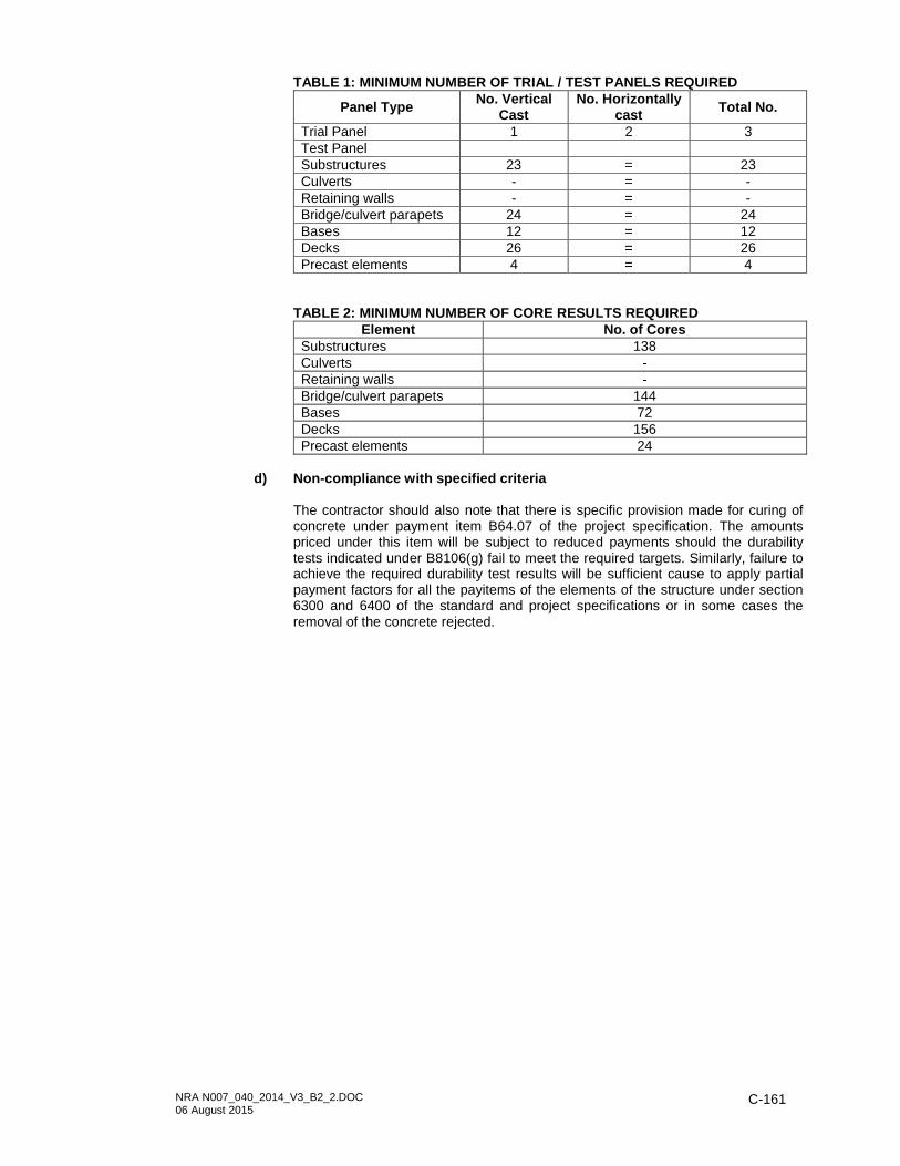
NRA N007_040_2014_V3_B2_2.DOC 06 August 2015
C-161
TABLE 1: MINIMUM NUMBER OF TRIAL / TEST PANELS REQU IRED
Panel Type No. Vertical Cast
No. Horizontally cast Total No.
Trial Panel 1 2 3 Test Panel Substructures 23 = 23 Culverts - = - Retaining walls - = - Bridge/culvert parapets 24 = 24 Bases 12 = 12 Decks 26 = 26 Precast elements 4 = 4
TABLE 2: MINIMUM NUMBER OF CORE RESULTS REQUIRED
Element No. of Cores Substructures 138 Culverts - Retaining walls - Bridge/culvert parapets 144 Bases 72 Decks 156 Precast elements 24
d) Non-compliance with specified criteria
The contractor should also note that there is specific provision made for curing of concrete under payment item B64.07 of the project specification. The amounts priced under this item will be subject to reduced payments should the durability tests indicated under B8106(g) fail to meet the required targets. Similarly, failure to achieve the required durability test results will be sufficient cause to apply partial payment factors for all the payitems of the elements of the structure under section 6300 and 6400 of the standard and project specifications or in some cases the removal of the concrete rejected.

NRA N007_040_2014_V3_B2_2.DOC 06 August 2015
C-162
SOUTH AFRICAN NATIONAL ROADS AGENCY SOC LIMITED CONTRACT NRA N007-040-2014/1 IMPROVEMENT OF THE OLIFANTS RIVER BRIDGE CROSSING AND ASSOCIATED WORKS ON NATIONAL ROUTE 7 SECTION 4 NEAR TRAWAL SECTION C: ENVIRONMENTAL MANAGEMENT PLAN

NRA N007_040_2014_V3_B2_2.DOC 06 August 2015
C-163
SECTION C: ENVIRONMENTAL MANAGEMENT PLAN TABLE OF CONTENTS PAGE C1001 SCOPE ................................................................................................................... C-164
C1002 DEFINITIONS ......................................................................................................... C-164
C1003 LEGAL REQUIREMENTS ...................................................................................... C-165
C1004 ADMINISTRATION OF ENVIRONMENTAL OBLIGATIONS ................................. C-167
C1005 TRAINING ............................................................................................................... C-168
C1006 ACTIVITIES/ASPECTS CAUSING IMPACTS ........................................................ C-169
C1007 ENVIRONMENTAL MANAGEMENT OF CONSTRUCTION ACTIVITIES ............. C-172
C1008 AREAS OF SPECIFIC IMPORTANCE ................................................................... C-179
C1009 REHABILITATION .................................................................................................. C-180
C1010 RECORD KEEPING ............................................................................................... C-180
C1011 COMPLIANCE AND PENALTIES .......................................................................... C-180
C1012 PROJECT SPECIFIC CONDITIONS ........... C-ERROR! BOOKMARK NOT DEFINED.

NRA N007_040_2014_V3_B2_2.DOC 06 August 2015
C-164
C1001 SCOPE
The Employer recognises environmental management as a key component of road infrastructure development and as part of its environmental policy has developed this Environmental Management Plan (EMPl) as a tool for continual improvement in environmental performance. This EMPl prescribes the methods by which proper environmental controls are to be implemented by the contractor. The duration over which the contractor’s controls shall be in place cover the construction period of the project as well as the limited time after contract completion defined by the Conditions of Contract for Construction for Building and Engineering Works Designed by the Employer (1999 edition) published by the Federation Internationale des Ingenieurs-Conseils (FIDIC) as the Defects Notification Period (maintenance period). The provisions of this EMPl are binding on the contractor during the life of the contract. They are to be read in conjunction with all the documents that comprise the suite of documents for this contract, particularly the conditions of any environmental authorisation and associated Environmental Management Programme (EMPr). In the event that any conflict occurs between the terms of the EMPl and the rest of the project specifications or environmental authorisation, the terms herein shall be subordinate. The EMPl is a dynamic document subject to similar influences and changes as are brought by variations to the provisions of the project specification. Any changes to the EMPl and/or environmental authorisation cannot occur without being submitted to the Employer who will manage the process of seeking approval of the change from the relevant authority. The EMPl identifies the following: - Relevant parties and their responsibilities; - Construction activities that will impact on the environment; - Specifications with which the contractor shall comply in order to protect the
environment from the identified impacts; and - Actions that shall be taken in the event of non-compliance.
C1002 DEFINITIONS
Alien Vegetation : undesirable plant growth which includes, but is not limited to all declared category 1 and 2 listed invader species as set out in the Conservation of Agricultural Resources Act (CARA), 1983 regulations. Other vegetation deemed to be alien are those plant species that show the potential to occupy in number, any area within the defined construction area and which are declared to be undesirable. Construction Activity : any action taken by the contractor, his sub-contractors, suppliers or personnel during the construction process as defined in the contract documents. Environment : the surroundings within which the contract exists and comprises land, water, atmosphere, micro-organisms, plant and animal life (including humans) in any part or combination thereof as well as any physical, chemical, aesthetic or cultural inter-relationship among and between them.. Environmental Aspect : any component of a contractor’s construction activity that is likely to interact with the environment. Environmental authorisation : a written statement from the National Department of Environmental Affairs, (DEA), with the general and specific conditions and the EMPr recording its approval of an application for a planned undertaking that triggers listed activities in the Environmental Impact Assessment (EIA) regulations of the National Environmental Management Act (NEMA). Environmental Impact : any change to the environment, whether desirable or undesirable, that will result from the effect of a construction activity. An impact may be the direct or indirect consequence of a construction activity.

NRA N007_040_2014_V3_B2_2.DOC 06 August 2015
C-165
Environmental Impact Assessment (EIA) : a systematic process of identifying, assessing and reporting environmental impacts associated with an activity and includes basic assessment and scoping and environmental impact reporting. Environmental Management Programme (EMPr) : the embodiment of this EMPl to ensure that undue or reasonably avoidable adverse impacts of a development are prevented, and to ensure that positive impacts are enhanced. It thus addresses the how, when, who, where and what of integrating environmental mitigation and monitoring measures through identified projects. Road Reserve : a corridor of land, defined by co-ordinates and/or proclamation, within which the road, including access intersections or interchanges, is situated. A road reserve may, or may not, be bounded by a fence. Site ; the site is defined in the FIDIC conditions of contract and in the scope of works. It is bound by the limits of construction as shown in the drawings or the title of the project and extends to also include the following:
- Areas outside the construction zones where accommodation of traffic is placed; - All borrowpits defined in the applications approved by the relevant Department of
Mineral Resources (DMR); - All haul roads constructed by the contractor for purposes of access; - Any non-adjacent sites specified in the contract documentation; - The contractor’s and his subcontractors’ camp sites; and
for the purposes of this EMPl includes areas outside of, but adjacent to, the road reserve that may be affected by construction activities. Spoil material : is material unsuitable for construction of the road pavement and for which no other useful purpose can be found in appurtenant works on the project (e.g. for the provision of protection beams). Such material is considered as waste material that requires spoiling at convenient areas to be identified by the engineer and/or contractor within the Site. Spoil material does not require removal to a designated landfill site unless it contains identifiable hazardous contaminants.
C1003 LEGAL REQUIREMENTS
(a) General
Construction shall be according to the best industry practices, as identified in the project documents. This EMPl, which forms an integral part of the contract documents, informs the contractor as to his duties in the fulfilment of the project objectives, with particular reference to the prevention and mitigation of environmental impacts caused by construction activities associated with the project. The contractor should note that obligations imposed by the EMPl are legally binding in terms of this contract. In the event that any rights and obligations contained in this EMPl contradict those specified in the standard or project specifications then the latter shall prevail.
(b) Statutory and other applicable legislation
The contractor is deemed to have made himself conversant with all legislation pertaining to the environment, including provincial and local government ordinances, which may be applicable to the contract. Major environmental legislation, as amended from time to time, includes but is not limited to the following:
(i) Conservation of Agricultural Resources Act (Act No. 43 of 1983)
This act provides for control over the utilisation of the natural agricultural resources of South Africa in order to promote the conservation of soil, water sources and vegetation, as well as combating weeds and invader plants.

NRA N007_040_2014_V3_B2_2.DOC 06 August 2015
C-166
(ii) The Constitution (Act 6 of 1996)
The Constitution states that everyone has the right to an environment that is not harmful to their health or well-being, and to have the environment protected through reasonable legislative and other measures to prevent pollution and ecological degradation; promote conservation and ensure ecologically sustainable development and use of natural resources.
(iii) Mineral and Petroleum Resources Development Act (Act No. 28 of 2002)
This act makes provision for equitable access to, and sustainable development of, minerals and petroleum resources.
(iv) National Environmental Management Act (NEMA), (Act No. 107 of 1998)
This act supports the Bill of Rights within the Constitution and highlights principles of sustainable development including preservation of ecosystems and biological diversity and avoidance, minimisation and remediation of pollution and environmental degradation. It also sets the stage for the EIA Regulations.
(v) National Environmental Management: Air Quality Act (Act No. 39 of 2004)
This act provides reasonable measures for the prevention of pollution and ecological degradation; and provides for specific air quality measures; for national norms and standards regulating air quality monitoring, management and control by all spheres of government.
(vi) National Environmental Management: Biodiversity Act (Act No. 10 of 2004)
This act makes provisions to accomplish the objectives of the United Nations’ Convention on Biological Diversity. The Employer may be required to apply for permits to conduct certain listed activities which, together with the listed threatened or protected species, may be identified by the Minister.
Section 73 (3) of this act empowers a competent authority to direct a person to take steps to remedy any harm to biodiversity resulting from the actions of that person or as a result of occurrence of listed invasive species occurring on land on which that person is the owner. Thus the Employer may be directed to remedy harm caused by listed invasive species.
(vii) National Environmental Management: Protected Areas Act (Act No. 57 of
2003)
This act provides for the protection and conservation of ecologically viable areas representative of South Africa’s biological diversity, natural landscapes and seascapes.
(viii) National Environmental Management: Waste Act (Act No. 59 of 2008)
This act aims to regulate waste management practices through provision of national norms and standards, specific waste measures, licensing and control of waste activities, remediation of contaminated land as well as providing for compliance and law enforcement.
(ix) National Forests Act (Act No. 84 of 1998)
This act makes provision for promoting the sustainable management and development of forests, and for the protection of certain forests and trees for environmental, economic, educational, recreational, cultural, health and spiritual purposes.

NRA N007_040_2014_V3_B2_2.DOC 06 August 2015
C-167
(x) National Heritage Resources Act (Act No. 25 of 1999)
This act provides for an integrated and interactive system for identification, assessment and management of South Africa’s heritage resources, and empowers civil society to nurture and conserve their heritage resources.
(xi) National Water Act (Act No. 36 of 1998)
This act makes provision for the protection of surface water and groundwater and their sustainable management for the prevention and remediation of the effects of pollution, as well as for the management of emergency situations.
C1004 ADMINISTRATION OF ENVIRONMENTAL OBLIGATIONS
Copies of this EMPl shall be kept at the site office and must be distributed to all senior contract personnel who shall familiarise themselves with its contents. Implementation of this EMPl requires the involvement of several stakeholders, each fulfilling a different but vital role as outlined herein, to ensure sound environmental management during the construction phase of a project.
(a) The Employer
The Employer is the holder of authorisations issued by the relevant environmental regulating authorities responsible for authorising and enforcing environmental compliance. The Employer and anyone acting on the Employer’s behalf is accountable for the potential impacts of the activities that are undertaken and is responsible for managing these impacts.
(b) The Engineer
The engineer has been appointed by, and acts for, the Employer as its on-site implementing agent and carries the responsibility to ensure that the contractor undertakes its construction activities in such a way that the Employer’s environmental responsibilities are not compromised. The engineer will, within seven days of receiving a contractor’s request for approval of a nominated Designated Environmental Officer (DEO), approve, reject or call for more information on the nomination. The engineer will be responsible for issuing instructions to the DEO where environmental considerations call for action to be taken. If in the opinion of the engineer the DEO is not fulfilling his/her duties in terms of this EMPl, the engineer may, after discussion and agreement with the Employer, exercise his powers under FIDIC condition of contract clause 6.9 and instruct replacement of the DEO in writing and with stated reasons.
(c) The Contractor
The contractor is responsible for project delivery in accordance with the prescribed specifications, among which this EMPl shall be included. The contractor shall receive and implement any instruction issued by the engineer relating to compliance with the EMPl including the removal of personnel or equipment. Compliance with the provisions contained herein or any condition imposed by the environmental approvals shall become the responsibility of the contractor through an approved Designated Environmental Officer (DEO). The contractor shall nominate a person from among his site personnel to fulfil this function and submit to the engineer for his approval the curriculum vitae of the proposed DEO. This request for approval shall be given, in writing, at least fourteen days before the commencement of any construction activity clearly setting out reasons for the nomination, and with sufficient detail to enable the engineer to make a decision.

NRA N007_040_2014_V3_B2_2.DOC 06 August 2015
C-168
(d) The Designated/Dedicated Environmental Officer (DEO )
Once a nominated representative of the contractor has been approved he/she shall become the DEO and shall be the responsible person for ensuring that the provisions of this EMPl are complied with during the life of the contract. The DEO shall submit regular written reports to the engineer, but not less frequently than once a month. The DEO may undertake other construction duties unless the Appendix to Tender prescribes this position as ‘dedicated’ as opposed to the standard position being ‘designated’. However, the DEO’s environmental duties shall hold primacy over other contractual duties and the engineer has the authority to instruct the contractor to reduce the DEO’s other duties or to replace the DEO if, in the engineer’s opinion, he/she is not fulfilling his/her duties in terms of the requirements of this EMPl. Such instruction will be in writing clearly setting out the reasons why a replacement is required. As a minimum the DEO shall have an accredited diploma qualification in environmental or natural sciences or equivalent. Alternatively, the DEO shall have a minimum of 2 years’ experience in a similar role in construction or other environmental regulatory field. In addition to the compliance duties relating to EMPl the DEO shall also provide full cooperation whenever the contractor is subjected to regular environmental audits.
(e) Environmental Control Officer (ECO)
The Environmental Control Officer (ECO) is an independent environmental specialist appointed by the engineer to objectively and regularly monitor the contractor’s implementation of this EMPl and the EMPr as may be determined by the sensitivity of the project or by conditions of authorisations. These are ‘internal’ audits and the regularity determined by the environmental approvals, usually once a month. Other ad hoc or ‘external’ audits ordered by the Employer may be conducted by other environmental specialists.
C1005 TRAINING
(a) Qualifications
The (DEO) shall have the minimum qualifications as prescribed above, and must be conversant with all legislation pertaining to the environment applicable to the contract. He/she must be appropriately trained in environmental management and possess the skills necessary to impart environmental management skills to all personnel involved in the contract. The contractor shall ensure that adequate environmental training takes place. All employees shall have been given an induction presentation on environmental awareness. Where possible, the presentation needs to be conducted in the language of the employees.
(b) Content
Apart from induction environmental training should, as a minimum, include the course content below and no induction or course should be given until the engineer has been afforded the opportunity to appraise it and provide comment.
(i) The importance of conformance with all environmental policies and the
consequences of departure from standard operating procedures;
(ii) Environmental impacts, actual or potential, caused by work activities, prevention measures to avoid them and mitigation measures when they occur;

NRA N007_040_2014_V3_B2_2.DOC 06 August 2015
C-169
(iii) Work force roles and responsibilities in achieving conformance with the
environmental policy and procedures and with the requirement of the Employer’s environmental management systems, including emergency preparedness and response requirements; and
(iv) The environmental benefits of improved personal performance.
(c) Induction
In the case of permanent staff the contractor shall provide evidence that such induction courses have been presented. In the case of new staff (including contract labour) the contractor shall inform the engineer when and how he intends concluding his environmental training obligations.
C1006 ACTIVITIES/ASPECTS CAUSING IMPACTS
Typical environmental aspects and impacts associated with road construction are listed in Table 1: Aspects and Impacts Associated with Road Construction. Actual impacts will differ from project to project and, therefore, so may the mitigation measures employed. The commonest aspects and impacts are addressed separately and typical avoidance and/or mitigation measures described. The list and descriptions are not by any means exhaustive and they shall be used for guideline purposes only. TABLE 1: ASPECTS AND IMPACTS ASSOCIATED WITH ROAD C ONSTRUCTION Aspect Impact Waste generation/storage Water pollution; nuisance; visual impact
Water use and stormwater discharge Change in flow regime and/or reduction in downstream availability; soil erosion: water pollution
Vehicle use and maintenance Air pollution; noise
Chemical/fuel storage Water/air/soil pollution; health impacts; accidents e.g. slips, fire
Site clearing; earthworks; layer-works; seal works
Change in landform; impact on heritage resources; noise; soil erosion; air pollution
River bridges; installing drainage structures
Water pollution; impact on river flows; noise
Land acquisition Loss of land &/or livelihood; change in land use;
Acquisition of building material from borrow pits Change in landform and use
(a) General approach
The role of the DEO cannot be underestimated and once approved he/she shall be on the site at all times, and before the contractor begins each construction activity he/she shall give to the engineer a written statement setting out the following:
(i) The type of construction activity about to be started. (ii) Locality where the activity will take place. (iii) Identification of the environmental aspects and impacts that might result
from the activity. (iv) The methodology of impact prevention for each activity or aspect. (v) The methodology of impact containment for each activity or aspect. (vi) Identification of the emergency/disaster potential for each activity (if any) and
the reaction procedures necessary to mitigate impact severity. (vii) Treatment and continued maintenance of impacted environment.
The contractor shall programme his work in such a way that each cause and effect of a construction activity is also identified and the activity planned so as to prevent any impact from happening and shall demonstrate that he is capable of carrying out any repair and reinstatement of the damaged environment. These requirements shall be concurrent with the time constraints to produce method

NRA N007_040_2014_V3_B2_2.DOC 06 August 2015
C-170
statements for each construction activity in compliance with the provisions of the project specifications. The contractor shall provide such information in advance of any or all construction activities provided that new submissions shall be given to the engineer whenever there is a change or variation to the original. The engineer may provide comment on the methodology and procedures proposed by the DEO, but he shall not be responsible for the contractor’s chosen measures of impact mitigation and emergency/disaster management systems. However, the contractor shall demonstrate at inception and at least once during the contract that the approved measures and procedures function properly.
(b) Spillages
Streams, rivers and dams shall be protected from direct or indirect spillage of pollutants such as refuse, garbage, cement, concrete, sewage, chemicals, fuels, oils, aggregate, tailings, wash water, organic materials and bituminous products. In the event of a spillage, the contractor shall be liable to arrange for professional service providers to clear the affected area. Responsibility for spill containment and treatment (whether hazardous or not) lies with the contractor. The individual causing a spill, or who discovers a spill, must report the incident to his/her DEO or to the engineer. The DEO will assess the situation in consultation with the engineer and act as required. In all cases, the immediate response shall be to contain the spill. The exact treatment of polluted soil / water shall be determined by the contractor in consultation with the DEO and the engineer. Areas cleared of hazardous waste shall be re-vegetated according to the engineer’s instructions. Should water downstream of the spill be polluted, and fauna and flora show signs of deterioration or death, specialist hydrological or ecological advice will be sought for appropriate treatment and remedial procedures to be followed. The requirement for such input shall be agreed with the engineer. The costs of containment and rehabilitation shall be for the contractor’s account, including the costs of specialist input as well as the sampling and testing of the water quality upstream and downstream of the spill. Water quality sampling and testing, and further treatment shall continue until upstream and downstream results correspond with each other.
(c) Water use and control
The contractor’s use of water shall take into consideration that it is a scarce commodity, and shall be optimised. Where applicable, authorisation shall be obtained from the Department of Water Affairs (DWA) before water is drawn from streams or new boreholes developed. The contractor shall also ensure that any stream deviations or diversions are undertaken in such a manner that the impact on the environment is minimised. Method statements shall be submitted to the engineer for comment, detailing how the work will be undertaken, what risks are foreseen and what measures will be employed to minimise such risks. Notwithstanding any comments by the engineer, no work on stream deviations or diversions can commence without written approval from DWA. The quality, quantity and flow direction of any surface water runoff shall be established prior to disturbing any area for construction purposes. Cognisance shall be taken of these aspects and incorporated into the planning of all construction activities. Before a site is developed or expanded, it shall be established how this development or expansion will affect the drainage pattern. Recognised water users / receivers shall not be adversely affected by the expansion or re-development. No water source shall be polluted in any way due to proposed changes.

NRA N007_040_2014_V3_B2_2.DOC 06 August 2015
C-171
Streams, rivers, pans, wetlands, dams, and their catchments shall be protected from erosion and from direct or indirect spillage of pollutants such as refuse, garbage, cement, concrete, sewage, chemicals, fuels, oils, aggregate, tailings, wash water, organic materials and bituminous products. The contractor shall submit to the engineer his proposals for prevention, containment and rehabilitation measures against environmental damage of the identified water and drainage systems that occur on the site. Consideration shall be given to the placement of sedimentation ponds or barriers where the soils are of a dispersive nature or where toxic fluids are used in the construction process. The sedimentation ponds must be large enough to contain runoff so that they function properly under heavy rain conditions up to a 1:5 year severity. The contractor shall submit to the engineer the results of monthly testing of water samples taken above and below the site of new culvert or bridge construction. No taking-over can be authorised until the water quality is shown to be at pre-construction levels or better.
(d) Vegetation management
The contractor shall be responsible for the management of vegetation by protection of indigenous vegetation, especially identified protected species, and the prevention of alien vegetation germinating in areas disturbed by road construction activities within and outside the road reserve. This includes, for example, service roads, stockpile areas, stop/go facilities, windrows and wherever material generated for or from road construction has been stored temporarily. This responsibility shall continue for the duration of the defects notification period.
(e) Dust control
Dust caused by construction activities shall be controlled by means such as water spray vehicles and applied at sufficient frequency so as not to cause nuisance to adjacent habitation or affect farming activities or natural vegetation. Vegetation cover should also be kept for as long as possible to reduce the area of exposed surfaces. Dust emissions from batching and screening plants shall be subject to the relevant legislation and shall be the subject of inspection by the relevant authorities.
(f) Noise control
The contractor shall endeavour to keep noise generating activities to a minimum. Noises that could cause a major disturbance, for instance blasting and crushing activities, should only be carried out during the hours prescribed by the conditions of contract (i.e. normal hours). Should such noise generating activities have to occur at any time outside normal hours the people in the vicinity of the noise-generating activity shall be warned about the noise well in advance and the activities kept to a minimum. Relevant legislation shall also be taken into consideration, and any practical mitigation measures adopted. No noise generating activity outside of normal hours, regardless of its proximity to residences, can take place without application to the engineer for approval. The application shall be accompanied by the noise containment measures proposed.
(g) Energy consumption
The contractor shall take into consideration the impacts of high energy consumption, both from a cost and emissions point of view. Energy use shall be minimised, and where possible, alternative energy sources such as solar utilised. Furthermore, the contractor shall undertake a study of the consumption of carbon units his chosen method of construction produces in the execution of his programme. In conjunction with the engineer who will provide complete cooperation in this study, a month by month output shall be compiled and efforts made to see how these outputs can be curtailed and reduced.

NRA N007_040_2014_V3_B2_2.DOC 06 August 2015
C-172
C1007 ENVIRONMENTAL MANAGEMENT OF CONSTRUCTION ACTI VITIES
The contractor shall undertake “good housekeeping” practices during construction as stated in the COLTO Standard Specifications for Roads and Bridges and the FIDIC conditions of contract. This will help avoid disputes on responsibility and allow for the smooth running of the contract as a whole. Good housekeeping extends beyond the wise practice of construction methods that leaves production in a safe state from the ravages of weather to include the care for and preservation of the environment within which the site is situated. The construction activities addressed below shall become part of the contractor’s obligations regarding his programme of work and incorporated into the required method statements for workmanship and quality control.
a) Site establishment
i) Site Plan
The site refers to an area with defined limits on which the project is located. The contractor shall establish his construction camps, offices, workshops, staff accommodation and testing facilities on the site in a manner that does not adversely affect the environment. However, before any site establishment can begin, the contractor shall submit to the ECO for his comments and to the engineer for his approval, plans of the exact location, extent and construction details of these facilities and the impact mitigation measures the contractor proposes to put in place.
The plans shall detail the locality as well as the layout of the waste management facilities for litter, kitchen refuse, sewage and workshop-derived effluents. The site offices should not be sited in close proximity to steep areas, as this will increase soil erosion. Preferred locations would be flat areas along the route. If the route traverses water courses, streams and rivers, it is recommended that the offices, and in particular the ablution facilities, aggregate stockpiles, spoil areas and hazardous material stockpiles are located as far away as possible from any water course. No camp establishment, including satellite camps, can be placed within 32 metres of an identified wetland unless the contractor has applied to DWA and DEA and received authorisation to do so. Regardless of the chosen site, the contractor’s intended mitigation measures shall be indicated on the plan. The site plan shall have been submitted and approved before establishment commences. Detailed, electronic colour photographs shall be taken of the proposed site before any clearing may commence. These records are to be kept by the ECO and the engineer for consultation during rehabilitation of the site in order that rehabilitation is, as a minimum, done to a standard similar to pre-construction activities.
ii) Vegetation
The contractor has a responsibility to inform his staff of the need to be vigilant against any practice that will have a harmful effect on vegetation. The natural vegetation encountered on the site is to be conserved and left as intact as possible. Vegetation planted at the site shall be indigenous and in accordance with instructions issued by the engineer. Only trees and shrubs directly affected by the works, and such others as may be indicated by the engineer in writing, may be felled or cleared. In wooded areas where natural vegetation has been cleared out of necessity, the same species of indigenous trees as were occurring shall be re-established. Protected trees may not be removed without a permit from the Department of Agriculture, Forestry and Fisheries. Contravention of a notice of listed protected tree species under the National Forests Act, 1998 is regarded as a first category offence that may result in a

NRA N007_040_2014_V3_B2_2.DOC 06 August 2015
C-173
fine or imprisonment for a period up to three years, or to both a fine and imprisonment. Rehabilitation shall be undertaken using only indigenous tree, shrub and grass species. Special attention shall be given to any search and rescue operation identified during the environmental application process, removal to an on site nursery for continuous nurturing and protection and later replanting. The contractor should be alert to this procedure and apply to the engineer to approve it even though no allowance has been made in the contract documents. Any proclaimed weed or alien species that propagates during the contract period shall be cleared by hand before seeding. Fires shall only be allowed in facilities or equipment specially constructed for this purpose. The need for a firebreak shall be determined in consultation with the engineer and the relevant authorities, and if required a firebreak shall be cleared and maintained around the perimeter of the camp and office sites. The contractor’s staff shall at no time make fires for purposes of keeping out the cold unless they are contained in purpose-built containers capable of preventing runaway fires if knocked over and the ashes collected and safely and environmentally disposed of on a daily basis.
iii) Water management
Water for human consumption shall be available at the site offices and at other convenient locations on site. All effluent water from the camp/office sites shall be disposed of in a properly designed and constructed system, situated so as not to adversely affect water sources (streams, rivers, pans, dams etc.). Only domestic type wastewater shall be allowed to enter this system.
iv) Heating and cooking fuel
The contractor shall provide adequate facilities for his staff so that they are not encouraged to supplement their comforts on site by accessing what can be taken from the natural surroundings. The contractor shall ensure that energy sources are available at all times for construction and supervision personnel for heating and cooking purposes.
b) Sewage management
Particular reference in the site establishment plan shall be given to the treatment of sewage generated at the site offices, site laboratory and staff accommodation and at all localities on the site where there will be a concentration of labour. Sanitary arrangements should be to the satisfaction of the engineer, the local authorities and legal requirements. Safe and effective sewage treatment will require one of the following sewage handling methods: septic tanks and soak-aways, dry-composting toilets such as “enviro loos”, or the use of chemical toilets which are supplied and maintained by a specialist service provider. The type of sewage management will depend on the geology of the area selected, the duration of the contract and proximity (availability) of providers of chemical toilets. Should a soak-away system be used, it shall not be closer than 800 metres from any natural water course or water retention system. The waste material generated from these facilities shall be serviced on a regular basis. The positioning of the chemical toilets shall be done in consultation with the engineer. Toilets and latrines shall be easily accessible and shall be positioned within walking distance from wherever employees are employed on the works. Use of the veld for this purpose shall not, under any circumstances, be allowed. Outside toilets shall be provided with locks and doors and shall be secured to prevent them from blowing over. The toilets shall also be placed outside areas

NRA N007_040_2014_V3_B2_2.DOC 06 August 2015
C-174
susceptible to flooding. The contractor shall arrange for regular emptying of toilets and shall be entirely responsible for enforcing their use and for maintaining such latrines in a clean, orderly and sanitary condition to the satisfaction of the engineer.
c) Waste management
The contractor’s intended methods for waste management shall be outlined and implemented at the outset of the contract, and shall be to the satisfaction of the engineer. Opportunities for avoiding, reducing, reusing and recycling of materials should be identified upfront, as should constraints for their implementation. All personnel shall be instructed to dispose of all waste in the proper manner.
i) Solid waste
Solid waste shall be stored in an appointed area in covered, tip-proof metal drums or similar container for collection and disposal. Disposal of solid waste shall be at a licensed landfill site or at a site approved by the relevant authority in the event that an existing operating landfill site is not within reasonable distance from the project area. No waste shall be burned or buried at or near the project area.
ii) Litter
No littering by construction workers shall be allowed and any locality where motorists are encouraged or forced to stop shall be effectively controlled for litter collection. During the construction period, the various contractor’s facilities shall be maintained in a neat and tidy condition and the site shall be kept free of litter. Measures shall be taken to reduce the potential for litter and negligent behaviour with regard to the disposal of all refuse. At all places of work the contractor shall provide litter collection facilities for later safe disposal at approved sites. Particular emphasis on litter control measures shall apply at stop/go facilities.
iii) Hazardous waste
Hazardous waste such as oils shall be disposed of at an approved landfill site. Special care shall be taken to avoid spillage of bitumen products such as binders or pre-coating fluid to avoid water-soluble phenols from entering the ground or contaminating surface water. Under no circumstances shall the spoiling of bituminous products on the site, over embankments, in borrow pits or any burying, be allowed. Unused or rejected bituminous products shall be returned to the supplier’s production plant. Any spillage of bituminous products shall be attended to immediately and affected areas shall be promptly reinstated to the satisfaction of the engineer.
iv) Construction and demolition waste
The opportunity for recycling and reuse of construction and demolition waste as fill for road embankments, land reclamation and drainage control must first be explored and take priority before the option of declaring these materials a ‘waste’. The contractor is encouraged to actively engage with authorities and landowners adjacent to the site and identify where such ‘waste’ materials can be usefully deployed to repair existing environmentally damaged areas such as erosion dongas.
d) Control at the workshop

NRA N007_040_2014_V3_B2_2.DOC 06 August 2015
C-175
The contractor’s management and maintenance of his plant and machinery will be strictly monitored according to the criteria given below, regardless of whether it is serviced on the site (i.e. at the place of construction activity or at a formalised workshop).
i) Hazardous Material Storage
Petrochemicals, oils and identified hazardous substances shall only be stored under controlled conditions. All hazardous materials such as bitumen binders shall be stored in a secured, appointed area that is suitably fenced, bunded and has restricted entry. Storage of bituminous products shall only take place using suitable containers to the approval of the ECO and the engineer. The contractor shall provide proof to the engineer that relevant authorisation to store such substances has been obtained from the relevant authority. In addition, hazard signs indicating the nature of the stored materials shall be displayed on the storage facility or containment structure. Before containment or storage facilities can be erected the contractor shall furnish the engineer with details of the preventative measures he proposes to install in order to mitigate pollution of the surrounding environment from leaks or spillage. The preferred method shall be a concrete floor that is bunded. Any deviation from the method will require proof from the relevant authority that the alternative method proposed is acceptable to that authority. The proposals shall also indicate the emergency procedures in the event of misuse or spillage that will negatively affect an individual or the environment.
ii) Fuel and gas storage
The contractor shall take cognisance of the limits set by legislation for the storage of fuels and acquire the necessary authorisation for storage capacity beyond these. All fuel shall be stored in a secure area in steel tanks supplied and maintained by the fuel suppliers. An adequate bund wall, 110% of volume, shall be provided for fuel and diesel areas to accommodate any leakage spillage or overflow of these substances. The area inside the bund wall shall be lined with an impervious lining to prevent infiltration of the fuel into the soil. Any leakage, spillage or overflow of fuel shall be attended to without delay. Gas welding cylinders and LPG cylinders shall be stored chained in a secure, well-ventilated area exterior to any building wall.
iv) Oil and lubricant waste
Used oil, lubricants and cleaning materials from the maintenance of vehicles and machinery shall be collected in a holding tank and sent back to the supplier. Water and oil should be separated in an oil trap. Oils collected in this manner, shall be retained in a safe holding tank and removed from site by a specialist oil recycling company for disposal at approved waste disposal sites for toxic/hazardous materials. Oil collected by a mobile servicing unit shall be stored in the service unit’s sludge tank and discharged into the safe holding tank for collection by the specialist oil recycling company. All used filter materials shall be stored in a secure bin for disposal off site. Any contaminated soil shall be removed and replaced. Soils contaminated by oils and lubricants shall be collected and disposed of at a facility designated by the local authority to accept contaminated materials.
e) Clearing the site
In all areas where the contractor intends to, or is required to clear the natural vegetation and soil, either within the road reserve, or at designated or instructed areas outside the road reserve, a plan of action shall first be submitted to the engineer for his approval. Working areas shall be clearly defined and demarcated

NRA N007_040_2014_V3_B2_2.DOC 06 August 2015
C-176
on site to minimise the construction footprint. ‘No-go- areas’ and other sensitive areas shall also be clearly demarcated on site, and staff must be made aware of them. The plan of action shall contain a photographic record and chainage/land reference of the areas to be disturbed. This shall be submitted to the engineer for his records before any disturbance/stockpiling may occur. The record shall be comprehensive and clear, allowing for easy identification during inspections.
f) Soil management
i) Topsoil
Topsoil shall be removed from all areas where physical disturbance of the surface will occur and shall be stored and adequately protected. The contract will provide for the stripping and stockpiling of topsoil from the site for later re-use. Topsoil is considered to be the natural soil covering, including all the vegetation and organic matter. Depth may vary at each site. The areas to be cleared of topsoil shall include all storage areas. All topsoil stockpiles and windrows shall be maintained throughout the contract period in a weed-free condition. Weeds appearing on the stockpiled or windrowed topsoil shall be removed by hand. Soils contaminated by hazardous substances shall be disposed of at an approved waste disposal site. The topsoil stockpiles shall be stored, shaped and sited in such a way that they do not interfere with the flow of water to cause damming or erosion, or itself be eroded by the action of water. Stockpiles of topsoil if they are to be left for longer than 6 months, shall be analysed, and if necessary, upgraded before replacement. Stockpiles shall be protected against infestation by weeds. The contractor shall ensure that no topsoil is lost due to erosion – either by wind or water. Areas to be top-soiled and grassed shall be done so systematically to allow for quick cover and reduction in the chance of heavy topsoil losses due to unusual weather patterns. The contractor’s programme shall clearly show the proposed rate of progress of the application of topsoil and grassing. The contractor shall be held responsible for the replacement, at his own cost, for any unnecessary loss of topsoil due to his failure to work according to the progress plan approved by the engineer. The contractor’s responsibility shall also extend to the clearing of drainage or water systems within and beyond the boundaries of the road reserve that may have been affected by such negligence.
ii) Subsoil
The subsoil is the layer of soil immediately beneath the topsoil. It shall be removed, to a depth instructed by the engineer, and if not used for road building it shall be stored and maintained separately from the topsoil so that neither stockpile is contaminated by the other. This soil shall be used for rehabilitation purposes by first spreading it over the excavated slopes without interfering with or contaminating the stockpiled topsoil. Whilst in stockpile it shall be maintained free from erosion and weed infestation in the same way as for topsoil stockpile maintenance.
g) Earthworks and layerworks
This section includes all construction activities that involve the mining of all materials, and their subsequent placement, stockpile, spoil, treatment or batching, for use in the permanent works, or temporary works in the case of deviations. Before any stripping prior to the commencement of construction, the contractor shall have complied with the requirements of this EMPl. In addition, the contractor shall take cognisance of the requirements set out below.
i) Quarries and borrow pits

NRA N007_040_2014_V3_B2_2.DOC 06 August 2015
C-177
The contractor’s attention is drawn to the requirement of the Department of Mineral Resources, that before entry into any quarry or borrow pit, an EMPr for the establishment, operation and closure of the quarry or borrow pit shall have been approved by the Department. It is the responsibility of the contractor to ensure that he is in possession of the approved EMPr or a copy thereof, prior to entry into the quarry or borrow pit. The conditions imposed by the relevant EMPr are legally binding on the contractor and may be more extensive and explicit than the requirements of this specification. In the event of any conflict occurring between the requirements of the specific EMPr and these specifications the former shall apply. The cost of complying with the requirements shall be deemed to be included in existing rates in the Pricing Schedule.
ii) Excavation, hauling and placement
The contractor shall provide the ECO and the engineer with detailed plans of his intended construction processes prior to starting any cut or fill or layer. The plans shall detail the number of personnel and plant to be used and the measures by which the impacts of pollution (noise, dust, litter, fuel, oil and sewage), erosion, vegetation destruction and deformation of landscape will be prevented, contained and rehabilitated. Particular attention shall also be given to the impact that such activities will have on the adjacent built environment. The contractor shall demonstrate his “good housekeeping”, particularly with respect to closure at the end of every day so that the site is left in a safe condition from rainfall overnight or over periods when there is no construction activity.
iii) Spoil sites
The contractor shall be responsible for the safe siting, operation, maintenance and closure of any spoil site he uses during the contract period, including the defects notification period. This shall include existing spoil sites that are being re-entered. Before spoil sites may be used proposals for their locality, intended method of operation, maintenance and rehabilitation shall be given to the ECO for his comments and to the engineer for his approval. The location of these spoil sites shall have signed approval from the affected landowner before submission to the ECO and the engineer. No spoil site shall be located within 500m of any watercourse. A photographic record shall be kept of all spoil sites for monitoring purposes. This includes before the site is used and after re-vegetation. The use of approved spoil sites for the disposal of hazardous or toxic wastes shall be prohibited unless special measures are taken to prevent leaching of the toxins into the surrounding environment. Such special measures shall require the approval of the relevant provincial or national authority. The same shall apply for the disposal of solid waste generated from the various camp establishments. The engineer will assist the contractor in obtaining the necessary approval if requested by the contractor. Spoil sites will be shaped to fit the natural topography. Depending on availability these sites shall receive a minimum of 75mm topsoil and be grassed with the recommended seed mixture. Appropriate grassing measures to minimise soil erosion shall be undertaken by the contractor. This may include both strip and full sodding. The contractor may motivate to the engineer for other acceptable stabilising methods. The engineer may only approve a completed spoil site at the end of the defects notification period upon receipt from the contractor of a landowner’s clearance notice and an engineer’s certificate certifying slope stability.
iv) Stockpiles
The contractor shall plan his activities so that materials excavated from borrow pits and cuttings, in so far as possible, can be transported direct to and placed at the point where it is to be used. However, should temporary

NRA N007_040_2014_V3_B2_2.DOC 06 August 2015
C-178
stockpiling become necessary, the areas for the stockpiling of excavated and imported material shall be indicated and demarcated on the site plan submitted in writing to the engineer for his approval, together with the contractor’s proposed measures for prevention of environmental damage, containment and subsequent rehabilitation. The areas chosen shall have no naturally occurring indigenous trees and shrubs present that may be damaged during operations. Care shall be taken to preserve all vegetation in the immediate area of these temporary stockpiles. During the life of the stockpiles the contractor shall at all times ensure that they are positioned and sloped to create the least visual impact, constructed and maintained so as to avoid erosion of the material and contamination of surrounding environment and kept free from all alien/undesirable vegetation. After the stockpiled material has been removed, the site shall be re-instated to its original condition. No foreign material generated / deposited during construction shall remain on site. Areas affected by stockpiling shall be landscaped, top soiled, grassed and maintained at the contractor’s cost until clearance from the engineer and the relevant national authority is received. Material milled from the existing road surface that is temporarily stockpiled in areas approved by the engineer within the road reserve, shall be subject to the same condition as other stockpiled materials. Excess materials from windrows, in situ milling or any detritus of material from road construction activities may not be swept off the road and left unless specifically instructed to do so in the contract documentation or under instruction from the engineer. In all cases, the ECO shall comment on and the engineer shall approve the areas for stockpiling and disposal of construction rubble before any operation commences and shall approve their closure only when they have been satisfactorily rehabilitated.
v) Blasting activities
Wherever blasting activity is required on the site (including quarries and/or borrow pits) the contractor shall rigorously adhere to the relevant statutes and regulations that control the use of explosives. In addition, the contractor shall, prior to any drilling of holes in preparation for blasting, supply the engineer with a risk assessment and locality plan of the blast site on which shall be shown the zones of influence of the ground and air shock-waves and expected limits of fly-rock. The plan shall show each dwelling, structure and service within the zones of influence and record the existing positions and conditions of the dwellings/structures/services including, lengths and widths of cracks, as well as the condition of doors, windows, roofing, wells, boreholes etc. The contractor, alone, shall be responsible for any costs that can be attributed to blasting activities, including the collection of fly-rock from adjacent lands and fields. The submission of such a plan shall not in any way absolve the contractor from his responsibilities in this regard. The contractor shall also indicate to the engineer the manner in which he intends to notify the adjacent communities and/or road users the times and delays to be expected for each individual blast.
h) On site plant
i) Crusher, screening plants and concrete batching plants
Crushing plants and concrete batching plants, whether sited inside or outside of defined quarry or borrow pit areas, shall be subject to the requirements of the applicable industrial legislation that governs gas and dust emissions into the atmosphere. Such sites will be the subject of regular inspections by the relative authorities during the life of the project. In addition, the selection, entry onto, operation, maintenance, closure and

NRA N007_040_2014_V3_B2_2.DOC 06 August 2015
C-179
rehabilitation of such sites shall be the same as for those under section C1007(g)(i) of this EMPl, with the exception that the contractor shall provide additional measures to prevent, contain and rehabilitate against environmental damage from toxic/hazardous substances. In this regard the contractor shall provide plans that take into account such additional measures as concrete floors, bunded storage facilities, linings to drainage channels and settlement dams. Ultimate approval of these measures shall be from the relevant national authority, as shall approval of closure. The engineer will assist the contractor in his submissions to the relevant authority. Screening activities shall be undertaken so that dust and noise is minimised. This can be done by carefully choosing the site for the activity, and by using slightly damp material. Effluent from concrete batch plants and crusher plants shall be reused where possible or treated in a suitable designated sedimentation dam to the legally required standards to prevent surface and groundwater pollution. The designs of such a facility should be submitted to the engineer for approval. The contractor shall invite the relevant department to inspect the site within 2 months after any plant is commissioned and at regular intervals thereafter, not exceeding 12 months apart.
ii) Asphalt Plant
Asphalt plants are considered to be one of the scheduled processes listed in the Environmental Impact Assessment Regulations of 2010. The activity triggered by the asphalt for road construction purposes is activity 26 of GN. R. 545, which states: “Commencing of an activity, which requires an atmospheric emission license in terms of Section 21 of the National Environmental Management: Air Quality Act, 2004 (Act No 39 of 2004) except where Activity 28 in Notice No R544 of 2010 applies.” Commencing with activity 26 of GN R. 545 requires Scoping and Environmental Impact Reporting (S&EIR) in order to obtain an environmental authorisation. In the event the use of an on-site asphalt plant is considered the contractor shall be responsible to obtain the necessary permit from the Department of Environmental Affairs, regardless of where the site is situated. Operation of the plant shall conform to the same requirements as for a crushing plant or concrete batching plant under C1007(h)(i) above.
C1008 AREAS OF SPECIFIC IMPORTANCE
Any area, as determined and identified within the project documents as sensitive or of special interest within the site shall be treated according to the express instructions contained in these specifications or the specific, approved EMPr. The contractor may offer alternative solutions to the engineer in writing should he consider that construction will be affected in any way by the hindrance of the designated sensitive area or feature. However, the overriding principle is that such defined areas requiring protection should not be changed. Every effort to identify such areas within the site will have been made prior to the project going out to tender. The discovery of other sites with archaeological or historical interest that have not been identified shall receive ad hoc treatment. A record of decision issued by Heritage Western Cape (HWC) was received on the 9th of December 2014, and indicated that nothing of heritage significance is expected to be impacted upon by the proposed bridge project.
a) Archaeological sites
If an artefact on site is uncovered, work in the immediate vicinity shall be stopped immediately. The contractor shall take reasonable precautions to prevent any person from removing or damaging any such article and shall immediately upon discovery thereof inform the engineer of such discovery. The South African Heritage Resource Agency (SAHRA) is to be contacted, and a SAHRA-registered

NRA N007_040_2014_V3_B2_2.DOC 06 August 2015
C-180
archaeological consultant may undertake the necessary work involved in confirming the find and advising on how it should be preserved or removed. Work may only resume once clearance is given in writing by the archaeologist. If a grave or midden is uncovered on site, or discovered before the commencement of work, then all work in the immediate vicinity of the graves/middens shall be stopped and the engineer informed of the discovery. The South African Heritage Resource Agency and the South African Police Services (SAPS) should be contacted and in the case of graves, arrangements made for an undertaker to carry out exhumation and reburial. The undertaker will, together with SAHRA, be responsible for attempts to contact family of the deceased and for the place where the exhumed remains can be re-interred.
C1009 REHABILITATION
The contractor shall be responsible for the re-establishment of grass within the road reserve boundaries for all areas disturbed during construction. This includes, for example, service roads, stockpile areas, stop/go facilities, windrows and wherever material generated for, or from, construction has to be stored temporarily, and designated or instructed areas outside the road reserve. It also includes the area where site offices were erected which may require rehabilitation at the end of the contract. All construction material, including concrete slabs and barbecue (braai) areas shall be removed from the site on completion of the contract unless written approval from the relevant landowner demonstrates it is to be left in place. Responsibility for re-establishment of vegetation shall extend until expiry of the defects notification period. However, the employer reserves the right to continue holding retention monies (or not releasing guarantees in lieu of retention) depending upon the state of cover at the end of the defects notification period. Such extension may continue until closure of the relevant quarry or borrow pit has been secured, Rehabilitation of affected areas should be undertaken as early as possible when the relevant activities are done in order to reduce further environmental damage. All re-vegetation should be undertaken using indigenous vegetation. The standard of rehabilitation should be to the satisfaction of the engineer and the relevant authorities. The Department of Minerals Resources will only issue closure certificates for borrow pits and quarries when they are satisfied with the rehabilitation undertaken. It should also be noted that in some cases there is a requirement for a final environmental audit covering the extent of the project.
C1010 RECORD KEEPING
The engineer and the DEO will continuously monitor the contractor’s adherence to the approved impact prevention procedures and the DEO shall submit regular written reports to the ECO and to the engineer, at least once a month. The engineer shall issue to the contractor a notice of non-compliance whenever transgressions are observed. The DEO shall document the nature and magnitude of the non-compliance in a designated register, the action taken to discontinue the non-compliance, the action taken to mitigate its effects and the results of the actions. The non-compliance shall be documented and reported to the engineer in the monthly report. Copies of any authorisations or EMPrs (including those for specific borrow pits or quarries used on the project) shall be kept on site and made available for inspection by visiting officials from the employer, relevant environmental departments or internal/external auditors.
C1011 COMPLIANCE AND PENALTIES
The contractor shall act immediately when a notice of non-compliance is received and correct whatever is the cause for the issuing of the notice. Complaints received regarding activities on the construction site pertaining to the environment shall be recorded in a dedicated register and the response noted with the date and action taken. This record shall be submitted with the monthly reports and an oral report given at the monthly site meetings.

NRA N007_040_2014_V3_B2_2.DOC 06 August 2015
C-181
Any non-compliance with the agreed procedures of the EMPr and this EMPl is a transgression of the various statutes and laws that define the manner by which the environment is managed and, therefore, any avoidable non-compliance, dependant on severity, may be considered sufficient grounds for contact to be made with relevant provincial or national authorities to invite their sanction.
The engineer’s decision with regard to what is considered a violation, its seriousness and the action to be taken against the contractor shall be final. Failure to redress the cause shall be reported to the relevant authority. The responsible provincial or national authority may ensure compliance and impose penalties relevant to the transgression as allowed within statutory powers.

NRA N007_040_2014_V3_B2_2.DOC 06 August 2015
C-182
Table 7/1: Mechanisms that Cause Environmental Impacts during Construction Activities
Section Contents
Environmental Impacts
Pollution Type Deformation of Landscape Soil erosion Alien Vegetation Sensitive Areas (to be completed by compiler)
1300 Camp Establishment
Waste treatment Hazardous waste Water supply Spillage Storage
Selection of site Preserve indigenous vegetation Preserve topsoil
Selection of site Preserve indigenous vegetation Preserve topsoil
Preserve indigenous vegetation Preserve topsoil Management of weeds
Refer to Volume 7
1400 Housing, Offices and laboratories
Waste treatment Hazardous waste Water supply Spillage Storage Noise/lights
Selection of site Preserve indigenous vegetation Preserve topsoil Demarcate sensitive areas
Selection of site Preserve indigenous vegetation Preserve topsoil
Preserve indigenous vegetation Preserve topsoil Management of weeds
Refer to Volume 7
1500 Accommodation of Traffic
Waste treatment Hazardous waste Water supply Spillage Storage Noise/lights Dust control
Selection of site Preserve indigenous vegetation Preserve topsoil Demarcate sensitive areas Maintenance of windrows
Selection of site Preserve indigenous vegetation Preserve topsoil
Preserve indigenous vegetation Preserve topsoil Management of weeds
Refer to Volume 7
1600 Overhaul
Spillage Storage Noise/lights Dust control Exhaust fumes Washing waste
Turning circles Parking areas
Restrict access to sensitive areas
Protection of indigenous vegetation Preserve topsoil
Refer to Volume 7
1700 Clearing and grubbing
Waste treatment Hazardous waste Water supply Noise /lights Dust control
Selection of site Preserve indigenous vegetation Preserve topsoil
Selection of site Preserve indigenous vegetation Preserve topsoil
Protection of indigenous vegetation Preserve topsoil
Refer to Volume 7
2100 -2400 Drainage
Waste treatment Hazardous waste Water supply
Selection of site Preserve indigenous vegetation
Selection of site Preserve indigenous vegetation
Preserve indigenous vegetation Preserve topsoil
Refer to Volume 7

NRA N007_040_2014_V3_B2_2.DOC 06 August 2015
C-183
Section Contents
Environmental Impacts
Pollution Type Deformation of Landscape Soil erosion Alien Vegetation Sensitive Areas (to be completed by compiler)
Spillage Storage
Preserve topsoil Preserve topsoil Management of weeds
3100 Borrow pits
Waste treatment Hazardous waste Water supply Spillage Storage
Selection of site Preserve indigenous vegetation Preserve topsoil
Selection of site Preserve indigenous vegetation Preserve topsoil
Preserve indigenous vegetation Preserve topsoil Management of weeds
Refer to Volume 7
3200 Stockpiling
Waste treatment Hazardous waste Water supply Spillage Storage
Selection of site Preserve indigenous vegetation Preserve topsoil
Selection of site Preserve indigenous vegetation Preserve topsoil
Preserve indigenous vegetation Preserve topsoil Management of weeds
Refer to Volume 7
3300 Mass Earthworks
Waste treatment Hazardous waste Water supply Spillage Storage
Selection of site Preserve indigenous vegetation Preserve topsoil
Selection of site Preserve indigenous vegetation Preserve topsoil
Preserve indigenous vegetation Preserve topsoil Management of weeds
Refer to Volume 7
3400 - 3900 Pavement layers
Waste treatment Hazardous waste Water supply Spillage Storage Noise / lights Dust control
Selection of site Preserve indigenous vegetation Preserve topsoil Demarcate sensitive areas Maintenance of windrows
Selection of site Preserve indigenous vegetation Preserve topsoil
Preserve indigenous vegetation Preserve topsoil Management of weeds
Refer to Volume 7
4100 Asphalt works / sealing operations
Waste treatment Hazardous waste Water supply Spillage
Selection of site Preserve indigenous vegetation Preserve topsoil
Selection of site Preserve indigenous vegetation Preserve topsoil
Preserve indigenous vegetation Preserve topsoil
Refer to Volume 7

NRA N007_040_2014_V3_B2_2.DOC 06 August 2015
C-184
Section Contents
Environmental Impacts
Pollution Type Deformation of Landscape Soil erosion Alien Vegetation Sensitive Areas (to be completed by compiler)
Storage Noise / lights Dust control Smoke control Storage of materials
Turning circles Parking areas
5000 Ancillary roadworks
Waste treatment Hazardous waste Water supply Spillage Storage
Selection of site Preserve indigenous vegetation Preserve topsoil
Selection of site Preserve indigenous vegetation Preserve topsoil
Preserve indigenous vegetation Preserve topsoil Management of weeds
Refer to Volume 7
6000 Structures
Waste treatment Hazardous waste Water supply Spillage Storage
Selection of site Preserve indigenous vegetation Preserve topsoil
Selection of site Preserve indigenous vegetation Preserve topsoil
Preserve indigenous vegetation Preserve topsoil Management of weeds
Refer to Volume 7
7000 Concrete pavements etc.
Waste treatment Hazardous waste Water supply Spillage Storage
Selection of site Preserve indigenous vegetation Preserve topsoil
Selection of site Preserve indigenous vegetation Preserve topsoil
Preserve indigenous vegetation Preserve topsoil Management of weeds
Not Applicable

NRA N007_040_2014_V3_B2_2.DOC 06 August 2015
C-185
SOUTH AFRICAN NATIONAL ROADS AGENCY SOC LIMITED CONTRACT NRA N007-040-2014/1 IMPROVEMENT OF THE OLIFANTS RIVER BRIDGE CROSSING AND ASSOCIATED WORKS ON NATIONAL ROUTE 7 SECTION 4 NEAR TRAWAL SECTION D: SMALL CONTRACTOR DEVELOPMENT, TRAINING A ND COMMUNITY
PARTICIPATION

NRA N007_040_2014_V3_B2_2.DOC 06 August 2015
C-186
SECTION D: SMALL CONTRACTOR DEVELOPMENT, TRAINING A ND COMMUNITY LIAISON TABLE OF CONTENTS PAGE D1001 SCOPE ................................................................................................................... C-187
D1002 DEFINITIONS AND APPLICABLE LEGISLATION ................................................ C-187
D1003 CONTRACT PARTICIPATION ............................................................................... C-188
D1004 COMMUNITY LIAISON .......................................................................................... C-189
D1005 TRAINING ............................................................................................................... C-190
D1006 LABOUR ENHANCED CONSTRUCTION ............................................................. C-194
D1007 MEASUREMENT AND PAYMENT ........................................................................ C-194

NRA N007_040_2014_V3_B2_2.DOC 06 August 2015
C-187
D1001 SCOPE
This section covers construction aspects relating to the processes by which the construction industry develops emerging and established small contractors, preferably from the Target Area. It also deals with labour enhanced construction by encouraging the engagement and training of labour recruited from local communities.
D1002 DEFINITIONS AND APPLICABLE LEGISLATION
(a) Definitions
Unless inconsistent with the context, in these specifications, the following terms, words or expressions shall have the meanings hereby assigned to them:
(i) Contract Participation
Contract Participation is a process by which the Employer implements Government’s objectives by setting targets relating to small contractor development and labour enhancement which the Contractor shall achieve as a minimum.
(ii) Contract Participation Goal (CPG)
Contract Participation Goal is the monetary value of the targets set by the Employer in the Contract Participation process.
(iii) Contract Participation Performance (CPP)
Contract Participation Performance is the measure of the Contractor’s progress in achieving the CPG.
(iv) Labour
Labour is the Contractor’s and Subcontractor’s personnel whose monthly earnings are derived from hours worked for a fixed hourly rate which is adjusted from time to time by legislation (as a statutory minimum) and the Contractor’s and Subcontractor’s employment policies.
(v) Target Area
Target Area is a defined area from which the Contractor is expected to recruit Targeted Labour. The Target Area for this contract is as indicated in the Appendix to Tender.
(vi) Targeted Enterprise
An enterprise which: a) is a contractor registered with the Construction Industry Board in a
contractor grading designation from 3 to 6 and status as potentially emerging; and
b) the Contractor has no equity holding in; and c) is a sub-contractor; and d) is registered in terms of the Company’s Act, 2008 (Act No. 71 of 2008)
or Close Corporation Act, 1984 (Act No. 69 of 1984); and e) is registered with the South African Revenue Service.
(vii) Target Groups
A Target Group is a specific section of the population who are South African citizens or have the legal right to work in South Africa and who are distinguished by gender, age or disability.

NRA N007_040_2014_V3_B2_2.DOC 06 August 2015
C-188
(viii) Targeted Labour
Targeted Labour is Labour recruited from the Target Area, who permanently reside in the Target Area or who are recognized as being residents of the Target Area on the basis of identification and association with and recognition by the residents of the Target Area.
(b) Applicable Legislation
The following Acts, as amended from time to time, are predominant amongst those which apply to the construction industry and are listed here for reference purposes only:
(i) The Constitution of South Africa; (ii) Public Finance Management Act No. 1 of 1999; (iii) Preferential Procurement Policy Framework Act No. 5 of 2000; (iv) Construction Industry Development Board Act No. 38 of 2000; (v) Broad-Based Black Economic Empowerment Act No. 53 of 2003.
D1003 CONTRACT PARTICIPATION
(a) Objective
A major objective of Government is to extend economic opportunities and entrepreneurial capacity to all localities by the optimum utilisation of the resources existing in the vicinity of projects, the development of these resources in the execution of the project, and by maximising the amount of project funds retained within the project locality. To this end, the contractor shall preferably recruit Targeted Enterprises from the Target Area.
(b) Contract Participation Targets
Contract participation is the process by which the Employer implements Government’s objectives. The Employer sets targets for construction by specified entities the rand value for which is based on the services and work undertaken by the specified entities and measured as a percentage of the Contractor’s final certified value of work completed (excluding VAT) measured at the date of issue of the Taking-over Certificate. The Contractor is obliged to commit to or exceed the targets stated in the Appendix to Tender. As far as it is practical, the Contractor should consider utilising small contractor resources from communities immediately adjacent to the contract before considering from wider areas.
(c) Contract Participation Goal (CPG)
The CPG is the monetary value of the targets set by the Employer and will be calculated as follows: CPG = final contract value (excluding VAT) x (% Targeted Labour + % Targeted Enterprise) The final contract value is the total value of certified work measured at the date of issue of the Taking-Over Certificate.
(d) Contract Participation Performance (CPP)
The CPP is the monetary value of the Contractor’s actual progress towards achievement of the CPG calculated as follows: CPP = total value (excluding VAT) of Targeted Labour contribution + Targeted Enterprise contribution The Contractor’s participation performance will be measured monthly in order to monitor the extent to which he is striving to reach the CPG. The basis of monitoring

NRA N007_040_2014_V3_B2_2.DOC 06 August 2015
C-189
shall be the levels of the individual contributions for Targeted Labour and Targeted Enterprise. Monthly returns, in the format provided by the Employer, are required from the Contractor and shall be submitted with each interim payment certificate. To assist in the measurement of CPP the Contractor shall include in his contract programme details of how he will achieve the CPG. The detail shall be provided not later than 1 (one) month after the engineer has accepted the original construction programme and updated with every subsequent revision. As an incentive to encourage the Contractor to exceed the CPG, a bonus is offered, measured as follows: The bonus = 0.05 x (CPP – CPG) up to a maximum of R250 000.00. Any bonus due (or portion thereof) shall be calculated at the completion of the contract or once the CPG has been exceeded whichever occurs sooner. No bonus shall apply if either the Targeted Labour, Targeted Enterprises and/or any individual Target Group targets are not reached. Conversely, failure to reach the CPG shall render the Contractor liable for a penalty as prescribed in clause 8.7 of the FIDIC Conditions of Contract. Penalties shall be calculated as follows: Penalty = 0.5 x (the value of the shortfall of Targeted Labour + the value of the shortfall of Targeted Enterprise). It shall be applied on a pro-rata basis according to a monthly evaluation of achievements against the programmed utilisation. It shall not apply to the individual Target Groups.
(e) Accredited Registration
CPP for Targeted Enterprises shall only be accepted if the respective Targeted Enterprises for which services or work is being claimed as having been performed, is registered with CIDB in one of the defined categories. In addition, documentary evidence that such Targeted Enterprises are registered with the South African Revenue Services (SARS) shall be lodged with the engineer before the work or service may be considered as having been performed by a Targeted Enterprise. The responsibility for producing evidence of the respective registration documentation shall rest with the Contractor. The Contractor shall assume responsibility for the compilation and maintenance of comprehensive records detailing each Targeted Enterprise progress during construction, starting from the award of a subcontract to a Targeted Enterprise until the successful completion of the subcontract work or termination of the subcontract. The Contractor may engage a small contractor who is not yet registered as a Targeted Enterprise and it then becomes a responsibility of the Contractor to assist with the registration process. If not successfully registered within the contract period, work completed by that small contractor shall not count towards CPP.
D1004 COMMUNITY LIAISON
(a) Purpose
“The purpose of community liaison is to create awareness between the Contractor and communities through which the contract passes. There is no need on this contract to create a project liaison committee (PLC), although it may be advisable that a community relations officer (CRO) is appointed from the Contractor’s ranks, for the specific purpose of acting as liaison between management and hired labour.”
(d) Use of the PLO
The purpose of the PLO is to facilitate liaison between the community, community

NRA N007_040_2014_V3_B2_2.DOC 06 August 2015
C-190
structures, local authorities, the contractor and the engineer. The engineer and contractor shall, at the start of the contract, agree on the duties of the PLO which may include the following: (a) communicating the labour requirements with regards to numbers and skills
to the community; (ii) determining, in consultation with the contractor, the needs of the labour for
training; (iii) identifying possible labour disputes and to assist in their resolution; (iv) informing labour of their conditions of temporary employment and to inform
labourers as soon as possible when their period of employment will be terminated;
(v) attending disciplinary proceedings to ensure that hearings are fair and reasonable;
(vi) attending meetings in which the community and/or labour is present or is required to be represented;
In terms of the Conditions of Contract, all labour recruitment, employment and associated risks shall remain the sole responsibility of the contractor.
D1005 TRAINING
(a) Purpose of training
The Employer has no service agreement or memorandum of understanding with any education and training quality assurance body and, therefore, does not function as the employer as defined under any three-party-agreement between the learner, the training provider and the employer. But the Employer desires similar outcomes to such agreements; specifically to train Targeted Enterprises and Targeted Labour and equip them with residual skills that can be used to gain meaningful future employment and qualifications that permit continued access to further learning and qualifications within a defined programme. The Employer will facilitate training and in this capacity demands continuous involvement in the necessary decision making and quality control process of the anticipated training within a skills program which identifies multiple but connected and full learnerships. The training shall be at both a theoretical and practical level and in accordance with the various laws and regulations contained in the South African Qualification Authority (SAQA) statutes. Wherever in this section reference is made to the selection and training of learners, any person, employed by any national, provincial or local authority, being it full time or part time, is expressly excluded from being considered for this training. The complete training programme shall be approved by the engineer before training can commence.
(b) Skills analysis
Before any training programmes can be approved the contractor shall complete a skills audit of his own employees and those of his subcontractors to determine existing qualifications and education received. The outcome of the analysis shall be used to create a training programme that will benefit both the employee and the construction industry at large. A separate skills analysis shall be conducted for the Targeted Enterprises with the specific purpose of identifying programmes that will develop and improve the ability of the owners of those enterprises to better manage their companies. The skills analyses and subsequent training programmes must be provided by a suitably qualified training practitioner (the training manager) whose services the contractor shall procure.

NRA N007_040_2014_V3_B2_2.DOC 06 August 2015
C-191
(c) The training provider
The training manager shall be the training provider in terms of his obligations and commitment to undertake the training required. In the event that the training manager does not himself have the requisite training qualifications he may include as part of his management team a person who does. Such person may be an institution/organisation, company, collaborative partnership or consultancy in which case, whoever is approved from that entity shall be dedicated to provide all training once the programme has been approved by the engineer. The training provider must be accredited and have in its employ Practitioners and/or Assessors registered with the Construction Education Training Authority (CETA) and who must have the necessary certified proof. Accreditation and registration proof shall be current, valid and list the NQF levels and unit standards for which he/she is accredited. The training and competency levels required of the training provider are given in the table below:
TABLE D1005/1: QUALIFICATIONS FOR TRAINING PERSONNE L
Designation Title & Unit Standard No NQF Level Credit
Practitioner Train the trainer; No 7384 4 16
Assessor Conduct outcome base assessment; No 115753 5 15
Moderator Conduct moderation of outcome based assessment; No 115759
6 10
In addition to the above qualifications, and in keeping with current CETA practical experience requirements for registration as a trainer, NQF level 4 training courses shall only be provided by a practitioner/assessor with NQF Level 5 (one level up) credentials. For this project the Employer requires the further qualification that assessors/moderators means persons who have been employed for at least 5 years as a site agent managing construction processes in the specific fields of roads maintenance, roads new construction, roads rehabilitation, structures, etc. It may be appropriate and effective to have different calibre/experienced personnel for each of the fundamental, core and elective training and assessment elements. In other words because the elective unit standards are more vocationally orientated and require specialist input, it is not expected that a single trainer/assessor will have all the necessary skills. In such cases, the training provider shall acquire an appropriate Practitioner/Assessor to perform elective training duties. Such appoint-ments shall be approved by the Employer.
(d) Training
(i) Skills programme
Recognised Prior Learning of each employee shall be investigated, and taken into account and incorporated into each skills programme along with the additional competencies identified as being capable of providing a full learnership outcome. It is recognised that the programme may consist of several unit standards but totalling insufficient credits for a full learnership qualification. Nevertheless, the competencies and credits achieved in a skills program should contribute to a full learnership by a later acquisition of the outstanding Unit Standards required for the full learnership. The skills programme must also be geared in such a way that a selected number of applicable and urgently required unit standards will equip a

NRA N007_040_2014_V3_B2_2.DOC 06 August 2015
C-192
learner with the minimum skills to become economically involved in the execution of the works as soon as possible. Studying for any learnership requires minimum literacy and numeracy competencies as defined by SAQA. The actual literacy and numeracy levels inform the training provider on how to conduct the selection process. Learners with grade 12 literacy, numeracy and computer skills will, in most cases, comply with the minimum learning necessities. However, a baseline assessment (for example by conducting mini RPL enquiries and tests) may be required to ensure that the competency levels still exist. Some fill-in skills programme of fundamental unit standards may be needed. Learners identified as having already acquired some tertiary training, particularly in the field of civil engineering, may be better suited to a more specialised learner programme. In other words the skills programme must reflect a degree of flexibility to cater for the different levels of competencies the selected learners will have and a single programme suitable for all learners should not be considered. All training shall take place within normal working hours, or as agreed with the trainees.
(ii) Targeted learnerships
The essential SAQA learnership criteria that must be applied by the training provider are given below for the sake of providing sufficient detail for the contractor to understand the Employer’s requirements: • minimum credits for qualification; • fundamental unit standards and credit values; • core unit standards and credit values; • elective units standards and credit values; • assumption that NQF level 3 language, computer and mathematical
competencies exist; • RPL processes; • exit level outcomes;
Notwithstanding the appearance of the above criteria in the contract document, they are not exhaustive and the training provider must apply the systems and processes provided by the relevant SAQA and other related legislation pertinent to training. The training provider shall constantly consult the SAQA website (www.saqa.org.za) page to ensure that the most current unit standard is used. In the event of any conflict, the legislated requirements shall apply. Before qualifying, the learners will be expected to demonstrate competence in a practical situation that integrates the assessment of all specific outcomes, for all unit standards in the learnership programme. When considering learnerships and skills programmes the training provider shall distinguish between levels of learning required. NQF level 5 training is not anticipated but may be applicable for some members of existing small contractors’ staff. The main training focuses on NQF levels 4 and 3. The former level is for the qualification title National Certificate: Supervision of Construction Processes, and is the prerequisite qualification for NQF level 5, National Diploma: Management of Civil Engineering Construction Processes. The NQF level 3 qualification title is National Certificate: Construction Roadworks. It may be necessary to include additional core unit standards (e.g. “tendering” as an additional unit standard for NQF level 4) in order to achieve project development objectives and identification of any additional unit standards shall be discussed with the engineer and cannot be implemented without prior approval.

NRA N007_040_2014_V3_B2_2.DOC 06 August 2015
C-193
(iii) Learning material
Learning material is required for each unit standard. This learning material is like prescribed books for other qualifications. It is a requirement for all the learners to receive a copy, to learn the contents, and also to serve as a reference source after qualification. The SAQA unit standards define the content of the learning material. The learning material must not only comply with the SAQA and CETA guidelines but must, and most importantly, be technically and practically aligned to road construction or road maintenance. Any input from a subject matter expert required to ensure the appropriateness of a particular unit standard subject is to be included in the training provider’s costs. The requirements to be addressed in learning material as outlined by the SAQA unit standard are, amongst others, the following: • The purpose of the unit standard; • Each of the specific outcomes (normally 4 per unit standard); • Each of the assessment criteria (normally 4 per specific outcome); • The range as is defined for each specific outcome; • The critical cross-field outcomes for the unit standard; • The unit standard essential embedded knowledge.
(e) Training facilities
The Contractor shall be responsible for the provision of everything necessary for the delivery of the various training workshops and modules including: (i) A suitable venue with sufficient furniture, lighting and power (ii) All necessary stationery consumables and study material (iii) Transport for attendants
Before commencing with any structured training the Contractor shall submit his intended programme to the engineer for approval of its subject content and proposed trainers, and the Contractor shall, if so instructed by the engineer, alter or amend the programme and/or course content.
(f) Generic skills training
Generic skills shall be taught where the need for these has been identified as being necessary. In this regard the contractor shall make representation to the engineer, who shall approve candidates that should attend such courses as thought appropriate. Those selected shall receive formal generic skills training in a programmed and progressive manner. The PLC and/or the engineer may also identify a need for generic skills training. Typical training programmes could comprise some or all of the following modules: (i) Basic hygiene and HIV/AIDS awareness (ii) Road safety (iii) Basic management of the environment (iv) Tourism awareness and opportunities (v) Managing personal finance
(g) Keeping of records
The training provider shall keep comprehensive records of the training given to each trainee and ensure that trainees’ successful completion of successive unit standards are entered onto the national database. With successful completion of generic skills courses each trainee shall be issued with a certificate indicating the course contents as proof of attendance and completion. The contractor shall keep a register of certificates issued in this regard. Whenever required, the contractor shall provide copies of such records to the engineer.

NRA N007_040_2014_V3_B2_2.DOC 06 August 2015
C-194
D1006 LABOUR ENHANCED CONSTRUCTION
The Contractor's attention is drawn to the fact that it is an objective of the contract to maximise the labour content of certain operations or portions thereof. In this regard, where the specified work allows for a choice between mechanical or labour-enhanced means, the former should generally be kept to the practical minimum. Before commencing with any labour enhanced operations the Contractor shall discuss his intentions with the engineer, and shall submit to the engineer on a monthly basis, daily labour returns indicating the numbers of temporary personnel employed on the works and the activities on which they were engaged.
D1007 MEASUREMENT AND PAYMENT
Item Unit
D10.01 Community participation
(a) Cost of community participation and PLC support ......... provisional sum (Prov) sum (b) Handling cost and profit in respect of sub-item D10.01(a) ................ percentage (%)
The provisional sum shall be used to cover the direct costs incurred by attending members of the PLC that the contractor establishes. The rate of compensation shall be at a fair rate agreed by the engineer. In accordance with clause 13.5 of the FIDIC Conditions of Contract, the tendered percentage for sub-item D10.01(b) shall include full compensation for all handling costs and profit of the contractor in connection with sub-item D10.01(a). The assistance provided by the contractor to the PLC in the form of in-task training, arranging service providers, appointment and services of a community relations officer shall not be paid from the provisional sum. The contractor’s costs to render such assistance shall be deemed to have been included in his rate offered for pay sub-item B13.01(c), Contractor’s Establishment on Site and General Obligations: Time Related Obligations.
Item Unit
D10.02 Training
(a) Generic skills ...............................................................................................................
(i) Training Costs ................................................................ prime cost (PC) sum (ii) Handling cost and profit in respect of subitem
D10.02(a)(i) .............................................................................. percentage (%) (b) NQF level 3 training .....................................................................................................
(i) Training Costs ................................................................. prime cost (PC) sum (ii) Handling cost and profit in respect of subitem
D10.02(b)(i) ............................................................................. percentage (%) (c) NQF level 4 training ....................................................................................................
(i) Training Costs ................................................................. prime cost (PC) sum (ii) Handling cost and profit in respect of subitem
D10.02(c)(i) ............................................................................. percentage (%) (d) Other costs during training ................................................................ provisional sum (e) Training venue ............................................................................................ lump sum
The prime cost sum under sub-items D10.02(a)(i), D10.02(b)(i) and D10.02(c)(i) shall be paid in accordance with the provision of sub-clause 13.5 of the FIDIC Conditions of Contract. The prime cost sums shall include all charges for provision and delivery of the service by accredited trainers including the cost of undertaking the required skills audits and analyses and creation of the individual training programmes. The rates tendered under sub-items D10.02(a)(ii), D10.02(b)(ii) and D10.02(c)(ii) shall be deemed to cover all costs required to organise accredited trainers to provide training and

NRA N007_040_2014_V3_B2_2.DOC 06 August 2015
C-195
shall include the contractor's handling cost, profit, record keeping, reporting and all other costs in connection therewith. The provisional sum under pay item D10.02(d) shall be paid in accordance with the provision of sub-clause 13.5 of the FIDIC Conditions of Contract. The provisional sum shall include wages of trainees during the duration of the courses, provision of meals, transport and all other incidentals required by the trainees and approved by the engineer. No mark-up is payable to the contractor under this item. The unit of measurement for pay item D10.02(e), shall be the lump sum. The sum tendered shall include full compensation for the provision of the training venue, for all necessary lighting, power, furniture, stationery, consumables and study material and all other costs necessary to maintain the venue for the duration of the contract. Payment of the lump sum shall be made in two instalments as follows: The first instalment, 75% of the lump sum, shall be paid after the contractor has met all his obligations regarding the provision of the training venue as specified. The second and final instalment, 25% of the lump sum, shall be paid after the provision of all the accredited training as specified in the document.
Item Unit D10.03 Bonus ......................................................................... provisional (Prov) sum
The provisional sum shall cover any CPP bonus due as specified in clause D1003. The provisional sum shall be expended in accordance with clause 13.5 of the FIDIC Conditions of Contract. Note: No separate payment shall be made for any costs incurred by the Contractor, whether direct or indirect, for his efforts in accomplishing the specified requirements, and which are not recoverable from the pay-items allowed. Such costs shall be deemed to have been included in the rate offered under pay sub-item 13.01(c), Contractor’s Establishment on Site and General Obligations: Time Related Obligations. No payment, nor pro rata payment, shall be made for trainees that, once selected, do not attend or only partially complete structured training courses. The contractor’s own staff may attend the courses provided. However, such attendants from the contractor’s staff shall not be considered for measurement and payment purposes unless they also qualify as Targeted Labour.

NRA N007_040_2014_V3_B2_2.DOC 06 August 2015
C-196
SOUTH AFRICAN NATIONAL ROADS AGENCY SOC LIMITED CONTRACT NRA N007-040-2014/1 IMPROVEMENT OF THE OLIFANTS RIVER BRIDGE CROSSING AND ASSOCIATED WORKS ON NATIONAL ROUTE 7 SECTION 4 NEAR TRAWAL SECTION E: REQUIREMENTS OF THE OCCUPATIONAL HEALTH AND SAFETY ACT AND
REGULATIONS Note to tenderer: Wherever reference is made in this section of the S cope of Works to contractor this is the equivalent of the principal contractor in the Occupational Health and Safety Act and Regulations. Similarly, reference to subcontractors is equivalent to other contractors.

NRA N007_040_2014_V3_B2_2.DOC 06 August 2015
C-197
SECTION E: REQUIREMENTS OF THE OCCUPATIONAL HEALTH AND SAFETY ACT AND REGULATIONS TABLE OF CONTENTS PAGE E1001 SCOPE ................................................................................................................... C-198
E1002 GENERAL OCCUPATIONAL HEALTH AND SAFETY PROVISIONS .................. C-198
E1003 OPERATIONAL CONTROL ................................................................................... C-203
E1004 PROJECT/SITE SPECIFIC REQUIREMENTS ...................................................... C-205

NRA N007_040_2014_V3_B2_2.DOC 06 August 2015
C-198
E1001 SCOPE
This part of the specification has the objective to assist the contractor entering into contracts with the Employer that they comply with the Occupational Health and Safety (OH&S) Act, No. 85 of 1993, as well as all applicable Regulations. Compliance with this document does not absolve the contractor from complying with minimum legal requirements and the contractor remains responsible for the health and safety of his employees and those of his Mandataries. The contractor shall therefore include this part of the specification to any contract that he may have with subcontractors and/or suppliers. This section covers the development of a health and safety specification that addresses all aspects of occupational health and safety as affected by this contract. It provides the requirements that the contractor shall comply with in order to reduce the risks associated with this contract, which may lead to incidents causing injury and/or ill health. In this matter the spirit and intention of Regulation 5(1)(l) of the Construction Regulations, 2014 regarding negotiations between the parties, related to the contents and approval of the Health and Safety Plan, must be complied with.
E1002 GENERAL OCCUPATIONAL HEALTH AND SAFETY PROVIS IONS
(a) Hazard Identification and Risk Assessment (Construc tion Regulation 9)
(i) Risk Assessments
Clause E1004 contains a generic list of risk assessment headings that have been identified by the Employer as possibly applicable to this contract. It is, by no means, exhaustive and is offered as assistance to the contractor.
(ii) Development of Risk Assessments
The contractor shall, before the commencement of any construction work or work associated with the aforesaid construction work and during such work, conduct a risk assessment by a competent person and the risk assessment so produced shall form part of the OH&S plan and be implemented and maintained as contemplated in Construction Regulation 9(1). Competence is a factor of training, knowledge, experience and/or appropriate qualifications. Where proof of competence is required by the Regulation, a concise CV must be attached to the appointment letter. The risk assessment shall include, as far as is reasonably practicable, at least: • the identification of the risks and hazards to which persons may be
exposed; • the analysis and evaluation of the risks and hazards identified,
inclusive of a residual risk rating methodology. The method to be used is not prescribed;
• a documented plan of safe work procedures, to mitigate, reduce or control those residual risks that have been identified as unacceptably high, by means of the rating system;
• a monitoring plan; • a review plan, inclusive of dates to be adhered to; and • ergonomic related risks are to be analysed, evaluated and addressed
as part of the process. Based on the risk assessments, the contractor shall develop a set of site-specific OH&S rules that shall be applied to regulate the OH&S aspects of the construction. The risk assessments, together with the site-specific OH&S rules shall be submitted to the Employer before construction on site commences. Despite the more advanced (or site specific) risk assessments listed below in clause E1004: PROJECT/SITE SPECIFIC REQUIREMENTS, the Employer would have conducted a baseline risk assessment before work commence and made the same available to the contractor. This does not

NRA N007_040_2014_V3_B2_2.DOC 06 August 2015
C-199
mean that all possible Risk Assessments must be attended to before work commences, but that all relevant Risk Assessments receive the necessary attention as the contract progresses, and this is the responsibility of the contractor. All variations to the scope of work shall similarly be subjected to a risk assessment process.
(iii) Review of Risk Assessment
The contractor shall review the hazard identification, risk assessments and standard working procedures at each production planning and progress report meeting as the contract work develops and progresses and each time changes are made to the designs, plans and construction methods and processes. The contractor shall provide the Employer, subcontractors and all other concerned parties with copies of any changes, alterations or amendments as contemplated above.
(b) Legal Requirements
The contractor shall, as a minimum, comply with: • The Occupational Health and Safety Act and Regulations (Act 85 of 1993), an up-
to-date copy of which shall be available on site at all times. • The Compensation for Occupational Injuries and Diseases Act (Act 130 of 1993),
an up-to-date copy of which shall be available on site at all times. • Where work is being carried out on a “mine”, the contractor shall comply with the
Mines Health and Safety Act and Regulations (Act 29 of 1960) and any other OH&S requirements that the mine may specify. An up-to-date copy of the Mines Health and Safety Act and Regulations shall be available on site at all times.
(c) Structure and Responsibilities
(i) Overall Supervision and Responsibility for OH&S
It is a requirement that the contractor, when he appoints subcontractors in terms of Construction Regulations 7(1)(c), 7(1)(d), 7(1)(f) and 7(3) includes in his agreement with such subcontractors the following:
• OH&S Act (85 of 1993), Section 37(2) agreement: “Agreement with
Mandatary” • OH&S Act (85 of 1993), Section 16(2) appointee/s as detailed in
his/her/their respective appointment forms. (Where applicable)
(ii) Further (Specific) Supervision Responsibilities for OH&S
The contractor shall appoint designated competent employees and/or other competent persons as required by the Act and Regulations. Below is a generic list of identified appointments and may be used to select the appropriate appointments for this contract. The contractor shall note that it is a generic list only and is intended for use as a guideline.
Appointment Regulation Construction manager (Contractor’s Representative), Assistant Construction Manager, Construction Supervisor, Assistant Construction Supervisor
(Construction Regulation 8(1), 8(2), 8(7) and 8(8)
Construction Vehicles and Mobile Plant/Machinery Supervisor
(Construction Regulation 23)
Demolition Supervisor (Construction Regulation 14) Drivers and Operators of Construction Vehicles or Plant
(Construction Regulation 23)
NRA N007_040_2014_V3_B2_2.DOC 06 August 2015
C-200
Electrical Installation and machinery on construction sites
(Construction Regulation 24)
Emergency/Security/Fire Coordinator
(Construction Regulation 29)
Excavation Supervisor (Construction Regulation 13) Explosive actuated fastening device
(Construction Regulation 21)
Fall Protection Supervisor (Construction Regulation 10) First Aider (General Safety Regulation 3) Fire Equipment Inspector (Construction Regulation 29) Temporary Works designer and Temporary Works Supervisor
(Construction Regulation 12)
Hazardous Chemical Substances Supervisor
(HCS Regulations)
Incident Investigator (General Admin Regulation 29) Ladder Inspector (General Safety Regulation 13A) Cranes (Construction Regulation 22) Materials Hoist Inspector (Construction Regulation 19) OH&S Committee (OH&S Act Section 19) Construction OH&S Officer (Construction Regulation 8(5) & 8(6) OH&S Representatives (OH&S Act Section 17) Person Responsible for Machinery
(General Machinery Regulation 2)
Scaffolding Supervisor (Construction Regulation 16) Stacking & Storage Supervisor (Construction Regulation 28) Structures Supervisor (Construction Regulation 11) Suspended Platform Supervisor (Construction Regulation 17) Tunnelling Supervisor (Construction Regulation 15) Bulk Mixing h Plants (Construction Regulation 20) Working on/next to Water Supervisor
(Construction Regulation 26)
Welding Supervisor (General Safety Regulation 9)
In addition the Employer requires that a Traffic Safety Officer be appointed. The above appointments shall be in writing and the responsibilities clearly stated together with the period for which the appointment is made. This information shall be communicated and agreed with the appointees. Notice of appointments shall be submitted to the Employer. All changes shall also be communicated to the Employer. The contractor shall, furthermore, provide the Employer with an organogram of all subcontractors that he/she has appointed or intends to appoint and keep this list updated and prominently displayed on site.
(iii) Designation of OH&S Representatives (Section 17 of the OH&S Act)
Where the contractor employs more than 20 persons (including the employees of subcontractors) he has to appoint one OH&S representative for every 50 employees or part thereof. This is a minimum (legal) requirement. The contractor may at his own discretion appoint more OH&S Representatives according to site specific requirements. General Administrative Regulation 6 requires that the appointment or election and subsequent designation of the OH&S representatives be conducted in consultation with employee representatives or employees. (Section 17 of the Act and General Administrative Regulation 6 & 7). OH&S representatives shall be designated in writing and the designation shall include the area of responsibility of the person and term of the designation. OH&S representatives must be experienced, permanently employed by the contractor or his subcontractors, trained and able to move freely within their designated area of responsibility.
(iv) Duties and Functions of the OH&S Representatives (Section 18 of the
OH&S Act)

NRA N007_040_2014_V3_B2_2.DOC 06 August 2015
C-201
The contractor shall ensure that the designated OH&S representatives conduct continuous monitoring and regular inspections of their respective areas of responsibility, focusing on unsafe acts and unsafe conditions and report thereon to the contractor. OH&S representatives shall participate in accident or incident investigations. OH&S representatives shall attend all OH&S committee meetings.
(v) Appointment of OH&S Committee (Sections 19 and 20 of the OH&S Act)
The contractor shall establish an OH&S committee, which shall meet at least once a month.
(d) Administrative Controls and the Occupational Health & Safety File
(i) The OH&S File (Construction Regulation 7(1)(b))
As required by Construction Regulation 7(1), the contractor and subcontractors shall each keep an OH&S file on site. The following index is neither exhaustive nor prescriptive but recommended as a guide for the contents of the OH&S file: • Notification of construction work (Construction Regulation 4) where
applicable • Latest copy of OH&S Act (General Administrative Regulation 4) • Proof of registration and good standing with COID Insurer
(Construction Regulation 5(1)(j) • OH&S plan agreed with the Employer including the underpinning risk
assessment/s and method statements (Construction regulation 7(1)) • Copies of OH&S committee and other relevant minutes • Designs/drawings (Construction Regulation 7(1)(e) • A list of subcontractors including copies of the agreements between
the parties and the type of work being done by each subcontractor (Construction Regulation 7(1)(f))
• Appointment/designation forms as per sub-sub-clause E1002(a)(i) and (ii).
• Registers as follows: - Accident/Incident register (Annexure 1 of the General
Administrative Regulations) - OH&S representatives’ inspection register - Asbestos demolition and stripping register - Bulk mixing plant inspections - Construction vehicles and mobile plant inspections by controller - Daily inspection of vehicles, plant and other equipment by the
operator/driver/user - Demolition inspection register - Designer’s inspection of structures record - Electrical installations, -equipment and -appliances (including
portable electrical tools) - Excavations inspection - Explosive actuated fastening device inspection, maintenance,
issue and returns register (incl. cartridges and nails) - Fall protection inspection register - First aid box contents - Fire equipment inspection and maintenance - Temporary works inspections - Hazardous chemical substances record - Ladder inspections - Lifting equipment register - Materials hoist inspection register - Machinery safety inspection register (incl. machine guards,
lock-outs etc.) - Scaffolding inspections - Stacking and storage inspection

NRA N007_040_2014_V3_B2_2.DOC 06 August 2015
C-202
- Inspection of structures - Inspection of suspended platforms - Inspection of tunnelling operations - Inspection of vessels under pressure - Welding equipment inspections - Inspection of work conducted on or near water - Welfare facilities as provided
(e) Notification of Construction Work (Construction Reg ulation 3)
The contractor shall, where the contract meets the requirements laid down in Construction Regulation 4 prior to commencement notify the Department of Labour of the intention to carry out construction work and use the form (Annexure 2 in the Construction Regulations) for the purpose. A copy shall be kept on the OH&S file and a copy shall be forwarded to the Employer for record keeping purposes.
(f) Training and Competence
The training required by the Act and Regulations shall be included in the contractor’s OH&S plan. The contractor shall be responsible for ensuring that all relevant training is undertaken. Only accredited training providers shall be used for the regulatory OH&S training. The contractor shall ensure that his and his subcontractors’ personnel appointed are competent and that all training required for doing the work safely and without risk to health, has been completed before work commences. The contractor shall ensure that follow-up and refresher training is conducted as the contract work progresses and the work situation changes. This does not absolve any subcontractors from their responsibilities as Employers. Records of all training must be kept on the OH&S file for auditing purposes.
(g) Consultations, Communication and Liaison
OH&S liaison between the Employer, the contractor, the subcontractors, the designer and other concerned parties will be through the OH&S committee as contemplated in sub-sub-clause E1002(c)(v). In addition to the above, communication may be directly to the Employer or his appointed agent, verbally or in writing, as and when the need arises. Consultation with the workforce on OH&S matters will be through their construction managers and supervisors, OH&S representatives and the OH&S committee. The contractor shall be responsible for the dissemination of all relevant OH&S information to the subcontractors e.g. design changes agreed with the Employer and the designer, instructions by the Employer and/or his/her agent, exchange of information between subcontractors, the reporting of hazardous/dangerous conditions/situations etc. The contractors’ most senior manager on site shall be required to attend all OH&S meetings.
(h) Checking, Reporting and Corrective Actions
(i) Monthly Audit by Employer (Construction Regulation 5(1)(o)
The Employer will conduct monthly health and safety and document verification audits in compliance with Construction Regulation 5(1)(o) in order to ensure that the contractor has implemented and is maintaining the agreed and approved OH&S plan.
(ii) Other Audits and Inspections by the Employer
The Employer reserves the right to conduct other ad hoc audits and inspections as deemed necessary. This will include site safety walks.

NRA N007_040_2014_V3_B2_2.DOC 06 August 2015
C-203
(iii) Contractor’s Audits and Inspections
The contractor must conduct his own regular internal audits to verify compliance with his own OH&S management system, as well as with this specification. The contractor shall furthermore ensure that each subcontractor`s health & safety plan is being implemented by conducting periodic audits at intervals mutually agreed between the contractor and subcontractors, but at least once per month.
(iv) Inspections by OH&S Representative’s and other Appointees
OH&S representatives shall conduct weekly inspections of their areas of responsibility and report thereon to their foreman or supervisor whilst other appointees shall conduct inspections and report thereon as specified in their appointments e.g. vehicle, plant and machinery drivers, operators and users must conduct daily inspections before start-up.
(v) Recording and Review of Inspection Results
All the results of the abovementioned inspections shall be in writing, reviewed at OH&S committee meetings, endorsed by the chairman of the meeting and placed on the OH&S File.
(i) Accidents and Incident Investigation (General Admin istrative Regulation 9)
The contractor and his subcontractors shall coordinate their investigation of all accidents/incidents where employees and non-employees were injured to the extent that he/she/they had to be referred for medical treatment by a doctor, hospital or clinic. The results of the investigation shall be entered into an accident/incident register listed in sub-sub-clause E1002(d)(i). The affected subcontractor shall be responsible for the investigation of all minor and non-injury incidents as described in Section 24(1)(b) & (c) of the Act and keeping a record of the results of such investigations including the steps taken to prevent similar accidents in future.
(j) Reporting
The contractor shall provide the Employer with copies of all statutory reports required in terms of the Act within 7 days of the incident occurring. In addition, the contractor shall update monthly the Disabling Injury Frequency Ratio (DIFR) and display this information on a signboard at the site office.
(k) Medical certificate of fitness (Construction Re gulation 7 (1) (g) and 7 (8) The Contractor as well as subcontractor (where appointed) shall ensure that all their employees have a valid certificate of fitness, specific to the construction work to be performed and issued by an occupational health practitioner, in the form of Annexure 3 to Government Gazette No. 37305 of 7 February 2014.
E1003 OPERATIONAL CONTROL
(a) Operational Procedures
Each construction activity shall be assessed by the contractor so as to identify operational procedures that will mitigate against the occurrence of an incident during the execution of each activity. This specification requires the contractor: - to be conversant with all relevant Regulations; - to comply with their provisions; - to include them in his OH&S plan where relevant.
(b) Emergency Procedures

NRA N007_040_2014_V3_B2_2.DOC 06 August 2015
C-204
Simultaneous with the identification of operational procedures (per sub-clause E1003(a) above), the contractor shall similarly identify and formulate emergency procedures in the event an incident does occur. The emergency procedures thus identified shall also be included in the contractor’s OH&S plan, and communicated as part of induction training. It is the responsibility of the first aid worker, together with the construction supervisor, to make an assessment regarding the severity of injuries and which actions are appropriate. For example: transfer to a medical facility by ambulance or helicopter.
(c) Personal & Other Protective Equipment (Sections 8/1 5/23 of the OH&S Act)
The contractor shall identify the hazards in the workplace and deal with them. He must either remove them or, where impracticable, take steps to protect workers and make it possible for them to work safely and without risk to health under the hazardous conditions. Personal protective equipment (PPE) should, however, be the last resort and there should always first be an attempt to apply engineering and other solutions to mitigating hazardous situations before the issuing of PPE is considered. Where it is not possible to create an absolutely safe and healthy workplace the contractor shall inform employees regarding this and issue, free of charge, suitable equipment to protect them from any hazards being present and that allows them to work safely and without risk to health in the hazardous environment. It is a further requirement that the contractor maintain the said equipment, that he instructs and trains the employees in the use of the equipment and ensures that the prescribed equipment is used by the employee/s. Employees do not have the right to refuse to use/wear the equipment prescribed by the Employer and, if it is impossible for an employee to use or wear prescribed protective equipment through health or any other reason, the employee cannot be allowed to continue working under the hazardous condition/s for which the equipment was prescribed but an alternative solution has to be found that may include relocating or discharging the employee. The contractor shall include in his OH&S plan the PPE he intends issuing to his employees for use during construction and the sanctions he intends to apply in cases of non-conformance by his employees. Conformance to the wearing of PPE shall be discussed at the weekly inspection meetings.
(d) Other Regulations
Wherever in the Construction Regulations or this specification there is reference to other regulations (e.g. Construction Regulation 24: Electrical Installations and Machinery on Construction Sites) the contractor shall be conversant with and shall comply with these regulations.
(e) Public Health & Safety (Section 9 of the OH&S Act)
The contractor shall, as far as is reasonably practicable, be responsible for ensuring that non-employees affected by the construction work are made aware of the dangers likely to arise from said construction work as well as the precautionary measures to be observed to avoid or minimise those dangers. This includes: • Non- employees entering the site for whatever reason • The surrounding community • Passers by to the site

NRA N007_040_2014_V3_B2_2.DOC 06 August 2015
C-205
E1004 PROJECT/SITE SPECIFIC REQUIREMENTS
The following is a generic list of Risk Assessment and Site specific health and safety specification prepared by the Employer in terms of construction Regulation 5(1)(a) and 5(1)(f):
• Clearing and Grubbing of the area/site • Site establishment including:
- Office/s - Secure/safe storage for materials, plant and equipment - Ablutions - Sheltered eating area - Maintenance workshop - Vehicle access to the site
• Dealing with existing structures • Location of existing services • Installation and maintenance of temporary construction electrical supply, lighting
and equipment • Adjacent land uses/surrounding property exposures • Boundary and access control/public liability exposures (NB: the Employer is also
responsible for the OH&S of non-employees affected by his/her work activities.) • Health risks arising from neighbouring as well as own activities and from the
environment e.g. threats by dogs, bees, snakes, lightning etc. • Exposure to noise • Exposure to vibration • Protection against dehydration and heat exhaustion • Protection from wet and cold conditions • Dealing with HIV/Aids and other diseases • Use of portable electrical equipment including
- Angle grinder - Electrical drilling machine - Circular saw
• Excavations including - Ground/soil conditions - Trenching - Shoring - Drainage of trench
• Welding including - Arc welding - Gas welding - Flame cutting - Use of LP gas torches and appliances
• Loading and offloading of trucks • Aggregate/sand and other materials delivery • Manual and mechanical handling • Lifting and lowering operations • Driving and operation of construction vehicles and mobile plant including
- Trenching machine - Excavator - Bomag roller - Plate compactor - Front end loader - Mobile cranes and the ancillary lifting tackle - Parking of vehicles and mobile plant - Towing of vehicles and mobile plant
• Use and storage of flammable liquids and other hazardous substances e.g. petrol, diesel, cement, asphalt, bituminous materials and similar
• Layering and bedding • Installation of pipes in trenches • Pressure testing of pipelines • Backfilling of trenches • Protection against flooding • Gabion work

NRA N007_040_2014_V3_B2_2.DOC 06 August 2015
C-206
• Use of explosives • Protection from overhead power lines • As discovered by the contractor’s hazard identification exercise • As discovered from any inspections and audits conducted by the Employer or by
the contractor or any subcontractor on site • As discovered from any accident/incident investigation.

NRA N007_040_2014_V3_B2_2.DOC 06 August 2015
C-207
SOUTH AFRICAN NATIONAL ROADS AGENCY SOC LIMITED CONTRACT NRA N007-040-2014/1 IMPROVEMENT OF THE OLIFANTS RIVER BRIDGE CROSSING AND ASSOCIATED WORKS ON NATIONAL ROUTE 7 SECTION 4 NEAR TRAWAL SECTION F: REHABILITATION OF STRUCTURES AND BRIDGES SERIES 12000: DRAFT SPECIFICATIONS FOR THE REHABILI TATION OF BRIDGES THAT SUPPLEMENT TO THE COLTO STANDARD SPECIFICATIONS FOR ROAD AND BRIDGE WORKS FOR STATE ROAD AUTHORITIES

NRA N007_040_2014_V3_B2_2.DOC 06 August 2015
C-208
SECTION F: REHABILITATION OF STRUCTURES AND BRIDGES TABLE OF CONTENTS PAGE SECTION 12 100: ACCESS FOR BRIDGE REHABILITATION .................................................... 209
SECTION 12 200: DEMOLITION AND REMOVAL OF STRUCTURAL CONCRETE ................... 214
SECTION 12 300: SURFACE AND STRUCTURAL REPAIR OF CONCRETE MEMBERS ......... 218
SECTION 12 400: GROUTING AND CRACK INJECTION ............................................................ 229
SECTION 12 600: PROTECTIVE COATINGS AND TREATMENTS FOR CONCRETE .............. 242
SECTION 12 700: EXTERNAL BONDING OF STEEL PLATES, BARS AND SECTIONS TO
CONCRETE SURFACES................................................................................. 249
SECTION 12 800: REPLACEMENT AND REPAIR OF ANCILLARY BRIDGE ELEMENTS ......... 260
SECTION 12 900: SURVEY AND TESTING OF SURFACE CONCRETE .................................... 265

NRA N007_040_2014_V3_B2_2.DOC 06 August 2015
C-209
SECTION 12 100: ACCESS FOR BRIDGE REHABILITATION F12 101 SCOPE
This specification covers the requirements for the provision of suitable and safe access to all areas requiring concrete demolition, repair work or rehabilitation of bridges in accordance with the contract, and for inspections by the engineer. This specification shall be read with the COLTO Standard Specifications for Road and Bridge Works for State Road Authorities (1998 edition), in particular Section 1200: General Requirements and Provisions, and Section 1300: Contractor’s Establishment on Site and General Obligations of the Standard Specification.
F12 102 INTERPRETATION
(a) Supporting specifications
The following specifications shall be read with, and shall form part of the contract:
� Project Specification
� COLTO Standard Specifications for Road and Bridge Works for State Road Authorities (1998 edition).
� SABS and BS standards referred to in this specification.
(b) Definitions
(i) Temporary works
The temporary works necessary for access to the work area includes all foundations, scaffolding and support structures, working platforms, cradles, fixtures to existing structural members, etc. required for the safe access to and execution of the work, and for the protection of passing persons, animals and vehicles against injury or damage and prevention of damage and littering to the environment.
(ii) Mobile access unit
A mobile access unit consists of a vehicle-mounted access gantry and work platform, including mobile crane type units.
(iii) Location
Location means a specific bridge as a whole where rehabilitation work has to be done.
(iv) Structural element
Setting up at each structural element as measured in the pricing schedule shall include all movement from point to point on a particular element. Structural elements are abutments, piers, decks and parapets/balustrades/edges of deck only. Other parts of a bridge shall be deemed to be included in the structural element to which they are most closely associated. A pier, abutment, deck or balustrade/parapet/ edge of deck may comprise single or multiple elements.
F12 103 GENERAL REQUIREMENTS
The contractor shall provide and will be responsible for safe access structures and work platforms to all areas requiring remedial work. The access and temporary works shall be designed, constructed and maintained in accordance with the current relevant safety regulations, all in compliance with the Occupational Health and Safety Act (Act 85 of 1993) and its applicable Regulations, and shall remain in place until removal is authorised

NRA N007_040_2014_V3_B2_2.DOC 06 August 2015
C-210
by the engineer. Appropriate allowances shall be made for screening of the work and other protective measures required by the various work activities. Access and work platforms may be provided from overhead mobile access gantries or vehicles, or from temporary works supported from the ground or fixed to structural members. The design and erection/construction of such temporary works shall be certified by a professional engineer on behalf of the contractor to comply with the relevant safety regulations regarding strength and stability for all imposed loads that can be anticipated to arise from the specified work activities. Notwithstanding approval given by the engineer for the design and drawings prepared by the contractor and the acceptance of temporary works including the working platform(s) and access structure(s) as constructed, the contractor shall be solely responsible for the safety and adequacy of the temporary works and shall indemnify and keep indemnified the employer and engineer against any losses, damage to persons or property, all claims, demands, proceedings, damages, costs, charges and expenses whatsoever, which may arise out of or in consequence of the design, construction, use and maintenance of the temporary works. For works on, over, under or adjacent to any railway line which is controlled by Transnet, the contractor shall comply, inter alia, with the requirements for the preparation and submission of drawings for falsework and formwork, and the submission of certificates for the proper construction thereof, all in accordance with the latest Transnet Specification, E7(2).The contractor shall submit to the engineer the relevant design details and drawings of the working platform(s) and access structures for comment and/or record purposes. Abseiling techniques shall not be allowed. The contractor shall comply with any additional imposed or physical restraints upon the means of access to and from the structure as stated in the project specification and/or the drawings. The contractor shall provide access facilities for inspection and testing by the engineer, including the inspection at the end of the maintenance period. Any specific access facility required for the inspection at the end of the maintenance period shall be as specified in the pricing schedule.
F12 104 MATERIAL
All timber, structural steel and scaffolding used shall be free from defects that may prejudice the stability of the working platform(s) and access structures. The jacks, devices, clamps and fittings shall all be in good working order and of adequate design and strength. The type, grade and condition of the material shall be subject to the engineer’s inspection.
F12 105 PLANT AND EQUIPMENT
(a) Mobile access units
Access structures and work platforms mounted and operated from a mobile vehicular support base shall be of an approved type and capacity for the intended use. The unit shall at all times be operated within the recommended limits in terms of reach and capacity as stated by the manufacturer or the authority responsible for the operation and maintenance of the access unit. The contractor shall, prior to dispatching the mobile access unit to the site, provide certification from the manufacturer or the operating authority that the unit has been thoroughly inspected and serviced, that the unit is functioning properly and that it complies with the relevant safety regulations.

NRA N007_040_2014_V3_B2_2.DOC 06 August 2015
C-211
(b) Scaffolds, platforms and cradles
Temporary works entailing scaffolds, platforms and cradles providing access to the work area shall be assembled and constructed from materials and structural sections complying with the relevant specifications. The temporary works shall be designed, erected, operated, maintained and dismantled so as to ensure safe working conditions for all site personnel, and where necessary the safety of the general public having access to the site.
F12 106 CONSTRUCTION
All temporary access structures and work platforms and associated works shall be erected, modified, maintained and dismantled under the direction of an experienced and competent supervisor or safety officer. Prior to using any temporary access structure or facility, and at regular intervals thereafter, or following unforeseen circumstances, the temporary works shall be inspected and certified by a suitably experienced and qualified person on behalf of the contractor. To ensure the safety of, and to prevent injury or damage to passing persons, vehicles, animals, etc. the temporary works shall be enclosed with a suitable screening membrane or boarding where necessary to contain material or work equipment within the limits of the restricted work area. Suitable debris containers and chutes shall be provided to assist in the removal of debris and unusable or rejected materials. Where temporary works are to be fixed to, or supported from an existing permanent structure, the location shall be subject to the approval by the engineer. Such temporary works shall be removed when the work is completed and any holes, surface damage or blemishes arising from the fixture shall be repaired to the surface finish of the adjacent surface to the satisfaction of the engineer.
F12 107 MEASUREMENT AND PAYMENT
The payment items in this clause shall include full compensation for all works items associated with the provision of suitable and safe access to all areas on site which are not already covered by the measurement and payment items of the Standard Specifications, i.e. all temporary works related to access structures and work platforms, or mobile access units including associated plant, equipment and labour. Item Unit F121.01 Temporary access structures and work platfo rms Access and platform to (height range indicated) (i) Design, supply and erect at the following structural
elements and height ranges inclusive of dismantling and moving to the next structural element ................................ lump sum/ meter/No
(ii) Dismantle and remove from location or structure ...................................... lump sum The unit of measurement for each subitem shall be either lump sum, meter or the number as scheduled. The height range shall be measured from the average ground surface to the agreed height limit accessed from the work platform. The height range shall be measured in the following height bands:
- 0m up to 5,0m - Exceeding 5,0m up to 10,0m

NRA N007_040_2014_V3_B2_2.DOC 06 August 2015
C-212
- Exceeding 10,0m up to 20,0m - Etc. in increments of 10m height
The tendered amount shall include full compensation for design, supply, fabrication, erection, dismantling, movement and for all labour, materials, and equipment required for the above works including the inspections, supervision by the safety officer and maintenance of the temporary access structure and work platform. The amount shall also include for all temporary traffic accommodation required during the deployment of the access equipment. Payment shall be made on completion of each subitem: Item Unit F121.02 Mobile access units
(a) Establishment of mobile access unit on site (description of unit) ............... lump sum (b) Setting up of mobile access unit at each location (bridge location)
and removal after completion ............................................................... number (No) (c) Operation of mobile access unit during repair work at each
location (bridge structure) ................................................................................... days (d) Operation of mobile access unit during inspections by the engineer .......... hours (h) (e) Standing time authorised by the engineer ................................................... hours (h) (f) De-establishing and removal of mobile access unit from site after
completion of work ..................................................................................... lump sum
The unit of measurement for each subitem shall be the lump sum, number or hours as indicated. The tendered amounts and rates shall include full compensation for all labour, plant and equipment required to procure, transport to site and to establish the mobile access unit including all costs related to inspection, operation and maintenance of the unit on site. The amount shall also include all temporary traffic accommodation required during the deployment of the access unit. The tendered rate for subitems (a) and (f) shall cover all costs necessary for establishing and de-establishing of the mobile access unit on site. The tendered rate for subitem (b) shall cover the cost for setting up of the mobile unit at each of the number of locations scheduled, and removal after completion of the work at the location. The tendered sum for subitem (c) shall cover all costs for operating the mobile access unit on location for the full time required to complete the repairs, depending on the critical path of the construction programme. Idle time and standing time shall not be measured separately and shall be deemed to be included in the tendered sum for operation of the mobile unit. The tendered rate for subitem (d) shall cover the cost of operation of the mobile access unit as required by the engineer. No payment shall be considered for this item if the engineer requires the use of the mobile access unit while it is on location for the normal work to be done under the contract and not specially re-established on the location for the purpose of inspection only. The tendered rate for subitem (e) shall cover the cost for standing time ordered or authorised by the engineer on occasions where the mobile access unit is specifically required for the use of the engineer.

NRA N007_040_2014_V3_B2_2.DOC 06 August 2015
C-213
Item Unit F121.03 Access at end of maintenance period
(Description of location) ............................................................... lump sum
The unit of measurement shall be the lump sum for access to each site at the end of the Defects Liability Period as ordered by the engineer The tendered amount shall include full compensation for all labour, material, plant or equipment including plant operators required to provide suitable and safe access for the engineer to carry out the necessary inspections as measured in the pricing schedule. Item Unit F121.04 Temporary access structures and work platf orms
(a) Access and platforms to locations as described as well as dismantling and removal
at completion (heights assessed by contractor)
(1) (Description of bridge given) (i) (Member of portion of work requiring access described) ....... lump sum (ii) (Etc. for other members of portion of work) ........................... lump sum
(2) (Etc. for other bridges)
(i) (Member of portion of work requiring access described) ....... lump sum (ii) (Etc. for other members of portion of work) ........................... lump sum
The unit of measurement for each subitem shall be the lump sum. The height of the required access platforms can be estimated from the drawings but must be confirmed on site. The heights must be assessed by the contractor at the time of tender. The tendered amount shall include full compensation for design, supply, fabrication, erection, dismantling, movement and for all labour, materials, and equipment required for the above works including the inspections, supervision by the safety officer and the maintenance of the temporary access structure and work platform. The amount shall also include for all temporary traffic accommodation required during the deployment of the access equipment. Payment shall be made on completion of each subitem. Item Unit F121.05 Attendance by (relevant authority)
(a) Prime cost sum to allow for attendance by relevant
authority to obtain access near electrified railway lines (give description of bridge) ............................................................... prime cost sum
(b) Percentage on prime cost sum for charges and profits ..................... percentage (%)
A prime cost sum is provided in the pricing schedule to cover the cost of this work. Payment for obtaining this service shall be in accordance with the provision of the FIDIC Conditions of Contract.

NRA N007_040_2014_V3_B2_2.DOC 06 August 2015
C-214
SECTION 12 200: DEMOLITION AND REMOVAL OF STRUCTURA L CONCRETE F12 201 SCOPE
This specification covers the work in connection with the demolition of entire members of a concrete structure as well as cutting back concrete to expose reinforcement and the initial preparation of the exposed surface. Surface and structural repair of concrete members is covered in Section 10 300.
F12 202 INTERPRETATION
(a) Supporting specification
The following specifications shall be read with, and form part of the contract:
(i) Project Specification (ii) COLTO Standard Specifications for Road and Bridge Works for State Road
Authorities (1998 edition) (iii) SABS and BS standards referred to in this specification
(b) Definitions
(i) Concrete members
All references to concrete members shall include mass concrete, un-reinforced, reinforced and prestressed concrete members.
(ii) Demolition of concrete members
Demolition means the breaking up and removal of an entire concrete member.
(iii) Removal of concrete
Removal of concrete means cutting back into the surface or end of a concrete member and the removal of unsound, damaged or contaminated concrete, or the partial removal of concrete sections, to expose a sound surface for bonding new material for the repair or extension of the concrete member.
F12 203 MATERIALS
All devices used to remove concrete or to demolish concrete members, shall be handled, stored and used strictly in accordance with the manufacturer’s instructions and current safety regulations.
F12 204 PLANT AND EQUIPMENT
(a) General
All plant, equipment, tools and devices used for the demolition of concrete members or the removal of portions of existing concrete shall be based on proven and accepted technology within the industry. The plant, equipment, tools and accessories shall be inspected and maintained on a regular basis to ensure that they remain in good working order, function efficiently, and that safety is not compromised. All cutting and breaking tools shall be kept sharp to reduce the force required to break out concrete to a minimum. The plant, equipment, tools and devices used for the demolition or removal process shall be of the accepted type and capacity for the relevant application. The suitability of the chosen method shall be demonstrated on a representative test section identified by the engineer prior to the execution of any programmed work.

NRA N007_040_2014_V3_B2_2.DOC 06 August 2015
C-215
(b) Access structures and working platforms
Where necessary, the contractor shall provide suitable and safe temporary access structures, working platforms, debris collection and removal chutes and bins, including protection screens where required, at each location where concrete has to be demolished or removed. The temporary structures, platforms, chutes, etc. must be stable and of sufficient strength and rigidity to safely carry the imposed temporary loads arising from the work activity, all as described in Section 12 100.
F12 205 CONSTRUCTION
(a) Sequence of execution
The method and sequence of demolition or removal of concrete shall be in accordance with the drawings or as directed by the engineer and the approved method statement submitted by the contractor following pre-construction testing if necessary. Any temporary propping specified in the approved method statement and the drawings shall be securely positioned in accordance with each stage of the demolition or removal sequence prior to commencement of the following stage.
(b) Site preparation and access
The necessary access and temporary support structures shall be in place prior to the commencement of demolition or removal of concrete. Screening and protective measures shall be established around the work area as necessary to ensure acceptable environmental, health and safety conditions.
(c) Demolition of concrete members
The demolition of entire concrete structures or major elements of a structure shall employ techniques that do not damage adjacent structures or structural elements, nor contaminate the surrounding environment except during special periods as may be approved by the engineer. The contractor shall ensure that any nuisance associated with his work activity is minimised by implementing appropriate precautions and measures to the approval of the engineer. Common nuisances associated with demolition and concrete removal include fumes, noise, dust, flying fragments, heat and vibration. Concrete members which are to be demolished completely shall be broken into suitably sized fragments to allow easy removal from site to an approved dump area. Recommended demolition techniques include the use of percussion breakers, chisels or other approved mechanical equipment, the use of thermal or hydraulic cutting techniques or by non-explosive chemical means, to ensure minimal damage (e.g. micro-cracking) to the existing concrete. Demolition by explosive means will normally not be acceptable and will be subject to the engineer’s written approval. Water jet removal of concrete is preferred wherever feasible.
(d) Removal of concrete from structural elements
(i) Cutting back concrete to a new finished surface
The concrete and reinforcement shall be cut back adequately to provide the prescribed concrete cover to the new finished surface as indicated on the drawings or as directed by the engineer. The technique used shall be suited to its intended purpose and shall not cause damage to the remaining concrete member.

NRA N007_040_2014_V3_B2_2.DOC 06 August 2015
C-216
Only techniques that do not damage the inherent structure, bond or strength of the remaining sound concrete shall be used. The thermal cutting technique shall not be used closer than 100mm from the final surface as indicated on the drawings. The remaining concrete shall be removed using approved mechanical equipment or hydraulic techniques. The fixed exposed contact surface shall be bounded by straight line edges cut at least 10mm deep by a diamond cutting saw, angle grinder or other approved equipment.
(ii) Cutting back concrete to expose reinforcement
Where a concrete member has to be joined or extended or replaced by new concrete, the concrete shall be carefully cut or broken from the reinforcement bars to expose the bars to the dimensions and outline as shown on the drawings or as directed by the engineer. Care shall be taken not to damage or reduce the strength of the exposed bars or concrete member thereby making them unfit for use. The remaining concrete contact surface shall be cut to a plane and even surface with exposed faces perpendicular to the horizontal face or side faces as applicable. The bounding lines of the cut concrete shall be straight and neat cut to at least 10mm depth using a diamond cutting saw, angle grinder or other approved concrete cutting equipment.
(e) Removal of metal sections embedded in concrete
Metal sections that are embedded in concrete members by means of grout pockets shall be removed by carefully chipping out the embedment grout filling the pocket. Care shall be taken not to damage the structural concrete surrounding the pocket. Suitable tools such as hand-held power tools with chisel bits or hand tools shall be used. Following the removal of the metal section, all remaining grout shall be removed and the pocket cleaned out to expose only solid concrete surfaces. The pocket shall be finally cleaned using high-pressure water jetting or oil-free compressed air to remove all loose fragments of grout, or concrete aggregate.
(f) Preparation of exposed contact surfaces
(For extension of existing concrete elements or con struction of new concrete members)
All loose and shattered concrete, as well as foreign material such as oil, paint, grease, etc. shall be removed from the contact surface of old concrete before new concrete is placed. The aggregate must be exposed to provide a good bonding surface. The mechanically prepared concrete surface shall be cleaned by means of oil-free compressed air or water jetting. The breaking out and preparation of damaged, spalled and/or cracked concrete surfaces is described and measured under the Sections 12 300 and 12 400.
(g) Disposal of waste material
All waste materials, rubble, scrap and rubbish arising from the contractor’s presence on site and/or the execution of the works shall be disposed of weekly to a disposal site identified by the contractor and approved by the engineer.
F12 206 TOLERANCES
The contractor shall remove concrete to a planar, uniform surface with 25mm maximum deviation from the level or dimension indicated on the drawings unless otherwise

NRA N007_040_2014_V3_B2_2.DOC 06 August 2015
C-217
approved by the engineer. The outer edge of the contact surface shall consist of straight lines with maximum deviation of 5mm from straight, measured with A 1m long straight edge, and shall be within 5mm of the position indicated on the drawings, or as instructed by the engineer.
F12 207 TESTING
The contractor shall carry out pre-construction tests with the proposed equipment to determine the suitability of the technique for the envisaged application. The test results shall be reported to the engineer and shall be subject to the engineer’s approval.
F12 208 MEASUREMENT AND PAYMENT
The payitems in this clause shall include full compensation for all work associated with the demolition and removal of concrete structural elements including initial preparation of concrete surfaces or portions thereof which are not already covered by the measurement and payment items of the Standard Specifications or the Project Specification, such as procurement, transport, access and temporary works, plant and equipment required to undertake the work as specified. General access, work platforms and associated temporary works are covered in Section 12 100. The quantities indicated in the pricing schedule under Section 12 200 are based on the dimensions shown on the drawings and on inspections carried out as part of the preliminary and detail design phases increased to allow for unseen work. It must, however, be accepted that the quantities of work actually done may vary significantly from the scheduled quantities, and that the contractor shall be deemed to have allowed in his tendered rates for such variations in quantities which can be reasonably expected. Item Unit F122.01 Demolition of concrete members (location
and description) .................................................................. cubic metre (m³)
The unit of measurement is the cubic metre of concrete demolished, measured in its original position and shape based on: (i) Full demolition (ii) Partial demolition The tendered rate shall include full compensation for all labour, material, screening of the structure for safety and environmental protective measures, equipment and plant as well as for all work and incidentals required to complete the work as specified and required to demolish the concrete member and to load, transport and dump the concrete segments and rubble at the nearest approved dumping site. See 12 205(g) Item Unit F122.02 Removal of metal sections embedded in conc rete
(description)
The unit of measurement shall be the number of metal sections removed. The tendered rate shall include full compensation for all labour, materials, equipment, screening of the structure and protective measures, required for the removal of the metal sections as described in 10 205(e) and disposal of all rubble at an approved waste disposal site, and the cleaning of the pocket as specified in 12 205(e).

NRA N007_040_2014_V3_B2_2.DOC 06 August 2015
C-218
SECTION 12 300: SURFACE AND STRUCTURAL REPAIR OF CO NCRETE MEMBERS F12 301 SCOPE
This specification covers the requirements for the surface and structural repair of structural concrete members. It covers the requirements for the removal of defective or contaminated concrete and/or reinforcement, the preparation of the exposed concrete surface and reinforcement for the rehabilitation of the member, and the repair or replacement of concrete with cementitious mortars, epoxy systems and proprietary concrete repair compounds. The removal of defective or contaminated concrete, partial removal of concrete sections and the initial preparation of contact surfaces are covered in Section 12 200.
F12 302 INTERPRETATION
(a) Supporting specifications
The following specifications shall be read with and shall form part of the contract: (i) Project Specification (ii) COLTO Standard Specifications for Road and Bridge Works for State Road
Authorities (1998 edition). F12 303 MATERIALS
(a) General
In addition to compliance with the requirements of the COLTO Standard Specifications Series 6000, materials shall comply with the relevant requirements of Clause 12 303(b).
(b) Cementitious mortar or concrete
Materials used in the cementitious mortar or concrete shall comply with the following requirements: (i) Cement
Cement shall be ordinary CEM.1. (42.5) or CEM.1. (42.5R).
(ii) Aggregates
Aggregates shall comply with the requirements of SABS 1083.
(c) Admixtures
Admixtures shall comply with the requirements of ASTM C-194 or AASHTO M-154 and shall be of an approved brand and type.
(d) Epoxy systems
Epoxy systems shall consist of a solvent-free, two-part adhesive consisting of a resin and hardener curing at ambient temperatures. The hardener shall be amine based with a high resistance to moisture. The epoxy shall be supplied and used in accordance with the manufacturer’s instructions and recommendations regarding the intended use thereof. Aggregate for epoxy mortars shall be kiln-dry when mixed with the epoxy system.

NRA N007_040_2014_V3_B2_2.DOC 06 August 2015
C-219
TABLE F12303/1: CHARACTERISTIC COMPRESSIVE STRENGTH (MINIMUM) OF EPOXY SYSTEM @ 25°C
Age
(days)
Compressive strength
(MPa)
1
3
7
60
80
90
(e) Proprietary cementitious repair compounds
The materials for proprietary cementitious repair compounds shall be supplied as a factory pre-packed dry premix of cements, aggregate and other proprietary products requiring only the addition of pre-packed liquid or a prescribed volume of water of an approved quality to produce the usable repair product. The proprietary repair compound shall compensate for shrinkage in both the plastic and hardened states and shall be suitable for use in the proposed mix and placing techniques. Proprietary concrete shall be highly workable and self-compacting without the use of vibrators. The aggregate grading shall be designed to prevent segregation during transportation and placing. The concrete system shall have a low alkali content to ensure minimal risk of alkali-silica reaction and shall contain no chlorides. The proprietary concrete shall comply with the material properties as indicated on the detail drawings, alternatively the following shall apply: TABLE F12303/2: CHARACTERISTIC COMPRESSIVE STRENGTH (MINIMUM) OF PROPRIETARY CEMENTITIOUS REPAIR COMPOUNDS ASTM C -109
Age Compressive strength
(MPa)
3 hours
1 day
7 days
28 days
12
25
35
40
TABLE F12303/3: BOND STRENGTH (MINIMUM) OF PROPRIET ARY CEMENTITIOUS REPAIR COMPOUNDS ASTM C-8823
Age Compressive strength
(MPa)
1 day
7 days
10
17
Thermal co-efficient of expansion (ASTM C531) 9,0 x 10⁻⁶ mm/mm/°C Modulus of Elasticity (Static): 30 GPa < Ec < 35 GPa - BS 1881 : Part 121 : 1983 All the necessary health, safety and fire precautions stated by the manufacturer shall be complied with. Only material of which the shelf life has not expired shall be used.
(f) Bonding agents
Non-cementitious bonding agents shall be either a single-component emulsion based on modified acrylic type resins or a slow-setting, solvent-free epoxy resin supplied as a two-part material, pre-packaged and ready for on-site mixing and application, and shall be of an approved brand and type suited to the application.

NRA N007_040_2014_V3_B2_2.DOC 06 August 2015
C-220
(g) Anti-corrosion primer for reinforcement
The anti-corrosion primer shall be a single component zinc rich primer with a minimum volume solids of 30% complying to a 700 hour salt spray resistance to exposure as per ASTM B-117. The primer shall be supplied and used in accordance with the manufacturer’s instructions and recommendations regarding the intended application. All necessary health, safety and fire precautions stated by the manufacturer shall be complied with.
F12 304 PLANT AND EQUIPMENT
All plant and equipment used for the preparation of concrete surfaces, batching of material and mixing operations shall be in good working order and suited for the intended use. The plant shall be inspected, serviced and calibrated at regular intervals and tested to ensure proper functioning, all to the satisfaction of the engineer.
F12 305 CONSTRUCTION
(a) Preparation of repair surfaces
(i) Preparation of concrete contact surface
All surface laitance and damaged, loose and soft concrete, concrete containing aggressive ions e.g. chloride, as well as all foreign materials such as oil, paint, grease, etc. shall be removed from the contact surface using pneumatic chisels or other approved mechanical equipment or thermal/hydraulic techniques. The contact surface shall be treated to expose the aggregate by means of chiselling, sand blasting or high-pressure water-jetting or where it can be shown to produce the required aggregate exposure, a hard brush may be used subject to the engineer’s approval. The mechanically prepared concrete surface shall be cleaned of dust by means of oil-free compressed air or water-jetting. The area to be repaired shall be bounded by straight line edges cut to the required depth using a diamond cutting saw, angle grinder or other approved equipment. The edges shall be recessed such that the patch has a thickness at the edge of at least twice the maximum aggregate size of the patching material, but in any case not less than 10mm.
(ii) Preparation and protection of embedded reinforcement
All visible or embedded reinforcement bars showing signs of corrosion shall be exposed by cutting back the concrete around the bar with pneumatic chisels or other approved method. The corrosion shall be removed by sand blasting, or where this is not warranted, by wire-brushing with power tools to an acceptable surface. The treated steel surface shall be clean of all corrosion and foreign material likely to impair the bond of the anti-corrosion primer to the reinforcement. No chemical solvents shall be used without the approval of the engineer. Reinforcement that has experienced significant pitting or reduction in diameter shall be referred to the engineer for acceptance. All rejected reinforcement shall be cut out and replaced with new bars of the same type and size, allowing for a minimum overlap of 45 diameter with the in situ bars. All exposed and cleaned reinforcement shall receive one coat of a single-component anti-corrosion primer based on zinc and epoxy resins, which shall be evenly applied to achieve a minimum 40 µm dry film thickness. The primer shall contain at least 30% zinc solids by volume. The primed surface shall not be exposed to the atmosphere longer than necessary before the application of the repair mortar, but at least until the coating is fully dry.