
Basic ARM InstructionS destination of the operation ...
19
09/05/2017 Comp 411 - Fall 2018 Basic ARM InstructionS ● Instructions include various “fields” that encode combinations of Opcodes and arguments ● special fields enable extended functions (more in a minute) ● several 4-bit OPERAND fields, for specifying the sources and destination of the operation, usually one of the 16 registers ● Embedded constants (“immediate” values) of various sizes, The “basic” data-processing instruction formats: 1 000 Opcode 0 Rn 1110 Rd 00000000 Rm R type: 001 Opcode 0 Rn 1110 Rd Imm Shift I type: 4 3 4 1 4 4 8 4 4 3 4 1 4 4 4 8
Transcript of Basic ARM InstructionS destination of the operation ...

09/05/2017 Comp 411 - Fall 2018
Basic ARM InstructionS
● Instructions include various “fields” that encode combinations of Opcodes and arguments
● special fields enable extended functions (more in a minute)● several 4-bit OPERAND fields, for specifying the sources and
destination of the operation, usually one of the 16 registers● Embedded constants (“immediate” values) of various sizes,
The “basic” data-processing instruction formats:
1
000 Opcode 0 Rn1110 Rd 00000000 RmR type:
001 Opcode 0 Rn1110 Rd ImmShiftI type:
4 3 4 1 4 4 8 4
4 3 4 1 4 4 4 8
09/05/2017 Comp 411 - Fall 2018
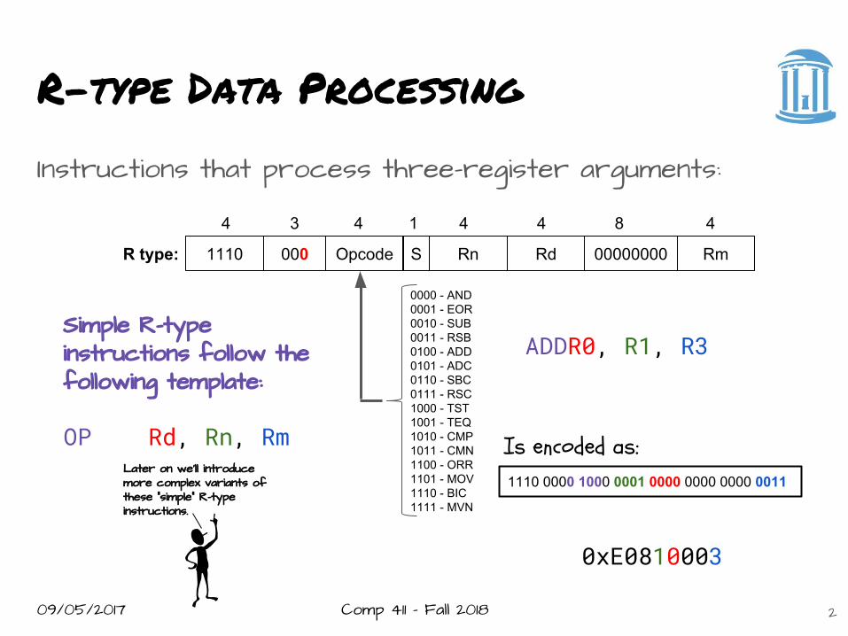
R-type Data Processing
Instructions that process three-register arguments:
2
000 Opcode S Rn1110 Rd 00000000 RmR type:
4 3 4 1 4 4 8 4
0000 - AND0001 - EOR0010 - SUB0011 - RSB0100 - ADD0101 - ADC0110 - SBC0111 - RSC1000 - TST1001 - TEQ1010 - CMP1011 - CMN1100 - ORR1101 - MOV1110 - BIC1111 - MVN
ADDR0, R1, R3
0xE0810003
Is encoded as:1110 0000 1000 0001 0000 0000 0000 0011
Simple R-type instructions follow the following template:
OP Rd, Rn, RmLater on we’ll introduce more complex variants of these “simple” R-type instructions.

09/05/2017 Comp 411 - Fall 2018
I-type Data Processing
3
Instructions that process two registers and a constant:
3
001 Opcode S Rn1110 Rd Imm8ShiftI type:
4 3 4 1 4 4 4 8
0000 - AND0001 - EOR0010 - SUB0011 - RSB0100 - ADD0101 - ADC0110 - SBC0111 - RSC1000 - TST1001 - TEQ1010 - CMP1011 - CMN1100 - ORR1101 - MOV1110 - BIC1111 - MVN
RSBR7,R10,#49
0xE26A7031
Is encoded as:1110 0010 0110 1010 0111 0000 0011 0001
Simple I-type instructions follow the following template:
OP Rd,Rn,#constantIn the I-type instructions the second register operand is replaced by a constant that is encoded in the instruction

09/05/2017 Comp 411 - Fall 2018
I-type constants
ARM7 provides only 8-bits for specifying an immediate constant value. Given that ARM7 is a 32-bit architecture, this may appear to be a severe limitation. However, by allowing for a shift (actually a “right rotation”) to be applied to the constant.
imm32 = (imm8 >> (2 * shift)) | (imm8 << (32 - (2 * shift)))
Example: 1920 is encoded as:
How would 256 be encoded?
4
000111101101 Shift Imm8
= (30 >> (2*13)) | (30 << (32 - (2*13)))
= 0 | 30 * 64 = 1920
000000011100 Shift Imm8

09/05/2017 Comp 411 - Fall 2018
Illustrating a right rotation
The “shift” field of the I-type instruction is a misnomer. It is acually a “rotate-right”. What’s a rotate right?
5
0000 00 0 1 1 1 0 0 0 100000 00 000000 00 000
0xB1 (209) rotated 4 postions to the right
Before:
0000 00 0 1 1 100000 00 000000 00 0000 0 0 1After:
0x10000009 (268,435,465)

09/05/2017 Comp 411 - Fall 2018 6
ARM immediate constants
Recall that immediate constants are encoded in two parts:Some constants can be encoded in multiple ways.Thus fewer than 409632-bit numbers can berepresented.There are actuallyonly 3073 distinctconstants. There are16, “0s” and 4 ways torepresent all powers 2.How might you encode256?
immShift 4 8
1100 00000001 1101 00000100
1110 00010000 1111 01000000

09/05/2017 Comp 411 - Fall 2018
Read the Instructions
.. when all else fails
● What do instructions do?● How are instructions decoded?● Uniformity and Symmetry● Cramming stuff in● CPU state
○ Condition codes○ Program Status Register (PSR)
7

09/05/2017 Comp 411 - Fall 2018
A closer look at the opcodes
The Opcode field is common to both of the basic instruction types
8
000 Opcode S Rn1110 Rd 00000000 RmR type:
4 3 4 1 4 4 8 4
001 Opcode S Rn1110 Rd Imm8RotateI type:
0000 - AND0001 - EOR0010 - SUB0011 - RSB0100 - ADD0101 - ADC0110 - SBC0111 - RSC1000 - TST1001 - TEQ1010 - CMP1011 - CMN1100 - ORR1101 - MOV1110 - BIC1111 - MVN
ARM data processing instructions can be broken into four basic groups:
● Arithmetic (6)● Logic (4)● Comparison (4)● Register transfer (2)
We haven’t discussed the “S” field yet. If set, it tells the processor to
retain some “state” after the instruction has executed.
This “state” is in the form of 5-flags.
Many instructions (all we’ve seen thusfar) have a special
variant that sets the state flags. In these variants the opcode has
an “S” appended.

09/05/2017 Comp 411 - Fall 2018
AritHmetic Instructions
ADD R3,R2,R12
SUB R0,R4,R6
RSB R0,R4,R2
ADC R1,R5,R8
SBC R2,R5,R7
RSC R1,R5,R3
9
R3 ← R2 + R12Registers can contain either 32-bit unsigned values or 32-bit 2’s-complement signed values.R0 ← R4 - R6Once more, either 32-bit unsigned values or 32-bit 2’s-complement signed values.R0 ← - R4 + R2The operands of the subtraction are in reversed order. It is called “Reverse Subtract”. Why? The I-type version makes more sense.R1 ← R5 + R8 + C Where “C” is the Carry-out from some earlier instruction (usually an ADDS or ADCS) as saved in the Program Status Register (PSR)R2 ← R5 - R7 - 1 + C Where “C” is the Carry-out from some earlier instruction (usually a SUBS or SUBCS) as saved in the PSRR1 ← - R5 + R3 - 1 + C“Reverse Subtract” with a Carry. Usually a carry generated from a previous RSBS or RSCS instruction.
1001101100000001A byte-sized example: 411 =
-42 = 0010101000000000 11010101
C=1
10011011
1
01110001
+11111111
1
00000001
1=1-1+C
00000001
+
= 256 + 113 = 369

09/05/2017 Comp 411 - Fall 2018
Logic Instructions
10
0000 0000 0000 0000 1111 1111 0000 0000
0000 0000 0000 0000 1111 0000 1111 0000
R1:
R2:
0000 0000 0000 0000 1111 0000 0000 0000AND R0,R1,R2 R0:
0000 0000 0000 0000 1111 1111 1111 0000ORR R0,R1,R2 R0:
Logical operations on words operate “bitwise”, that is they are applied to corresponding bits of both source operands.
0000 0000 0000 0000 0000 1111 1111 0000EOR R0,R1,R2 R0:Commonlycalled“exclusive-or”
0000 0000 0000 0000 0000 1111 0000 0000BIC R0,R1,R2 R0:Called “Bit-clear”R0 ← R1 & ~(R2)

09/05/2017 Comp 411 - Fall 2018
Status Flags
Now it is time to discuss what status flags are available. These five status flags are kept in a special register called the Program Status Register (PSR). The PSR also contains other important bits that control the processor.
● N - set if the result of an opeartion is negative (Most Significant Bit (MSB) is a 1)
● Z - set if the result of an operation is “0”● C - set if the result of an operation has a carry out of it’s MSB● V - set if a sum of two positive operands gives a negative result, or
if the sum of two negative operands gives a positive result● Q - a sticky version of overflow created by instructions that
generate multiple results (more on this later on).
11

09/05/2017 Comp 411 - Fall 2018
Comparison InstruCtions
These instructions modify the status flags, but leave the contents of the registers unchanged. They are used to test register contents, and they must have their “S” bit set to “1”. They also don’t modify their Rd, and by convention, Rd is set to “0000”.
CMP R0,R1
CMN R2,R3
TST R4,#8
TEQ R5,#102
12
PSR flags set for the result R2 + R3
PSR flags set for the result R4 & 8
PSR flags set for the result R5 ^ 1024
PSR flags set for the result R2 - R3

09/05/2017 Comp 411 - Fall 2018
Register Transfer
These instructions are used to transfer the contents of one register to another, or simply to initialize the contents of a register. They make use of only one operand, and, by convention, have their Rn field set to “0000”.
MOV R0,R3
MOV R1,#4096
MVN R2,R4
MVN R3,#1
13
R0 ← R3
R1 ← 4096
R2 ← - R4
R3 ← - 1

09/05/2017 Comp 411 - Fall 2018
ARM Shift Operations
A novel feature of ARM is that all data-processing instructions can include an optional “shift”, whereas most other architectures have separate shift instructions. This is actually very useful as we will see later on. The key to shifting is that 8-bit field between Rd and Rm.
14
000 Opcode S Rn1110 Rd Shift RmR type:
4 3 4 1 4 4 5 2 1 4LA
0
Shift Amount0-31 bits
Shift Type00 - logical left01 - logical right10 - arithmetic right11 - rotate right

09/05/2017 Comp 411 - Fall 2018
Left Shifts
Left Shifts effectively multiply the contents of a register by 2s where s is the shift amount.
MOV R0,R0,LSL #7
Shifts can also be applied to the second operand of any data processing instruction
ADD R1,R1,R0,LSL #7
15
0000 0000 0000 0000 0000 0000 0000 0111R0 before:
0000 0000 0000 0000 0000 0011 1000 0000R1 after:
= 7
= 7 * 27 = 896

09/05/2017 Comp 411 - Fall 2018
Right Shifts
Right Shifts behave like dividing the contents of a register by 2s where s is the shift amount, if you assume the contents of the register are unsigned.
MOV R0,R0,LSR 2
16
0000 0000 0000 0000 0000 0100 0000 0000R0 before:
0000 0000 0000 0000 0000 0001 0000 0000R1 after:
= 1024
= 1024 / 22 = 256

09/05/2017 Comp 411 - Fall 2018
Arithmetic Right Shifts
Arithmetic right Shifts behave like dividing the contents of a register by 2s where s is the shift amount, if you assume the contents of the register are signed.
MOV R0,R0,ASR #2
17
1111 1111 1111 1111 1111 1100 0000 0000R0 before:
1111 1111 1111 1111 1111 1111 0000 0000R1 after:
= -1024
= -1024 / 22 = -256

09/05/2017 Comp 411 - Fall 2018
Rotate RiGHT Shifts
Rotating shifts have no arithmetic analogy. However, they don’t lose bits like both logical and arithmetic shifts. We saw rotate right shift used for the I-type “immediate” value earlier.
MOV R0,R0,ROR #2
Why no rotate left shift?
● Ran out of encodings?● Almost anything Rotate lefts can do ROR can do as well!
18
0000 0000 0000 0000 0000 0000 0000 0111R0 before:
1100 0000 0000 0000 0000 0000 0000 0001R1 after:
= 7
= -1,073,741,823

09/05/2017 Comp 411 - Fall 2018
Next time
Instructions still missing
● Access to memory● Branches and Calls● Control● Multiplication? ● Division?● Floating point?
19