
Axcess January Digest - financial sector updates and Axcess company news
ProcessesMulti-MIG®
Accu-Pulse® MIG (GMAW-P)- Accu-Curve™
- Accu-Speed™ OptionalPulsed MIG (GMAW-P)MIG (GMAW)Metal CoreRMD™ (GMAW-SCT) OptionalCarbon Arc Gouging (CAC-A) can also be activated
FREE TRIAL! See page 2 for detailsAccu-Speed™ (GMAW-P)RMD™ (GMAW-SCT)
ManufacturingApplicationsConstruction EquipmentAutomotive ComponentsRecreational VehiclesFarm MachineryOffice FurnitureMining Machinery
QuickSpecs
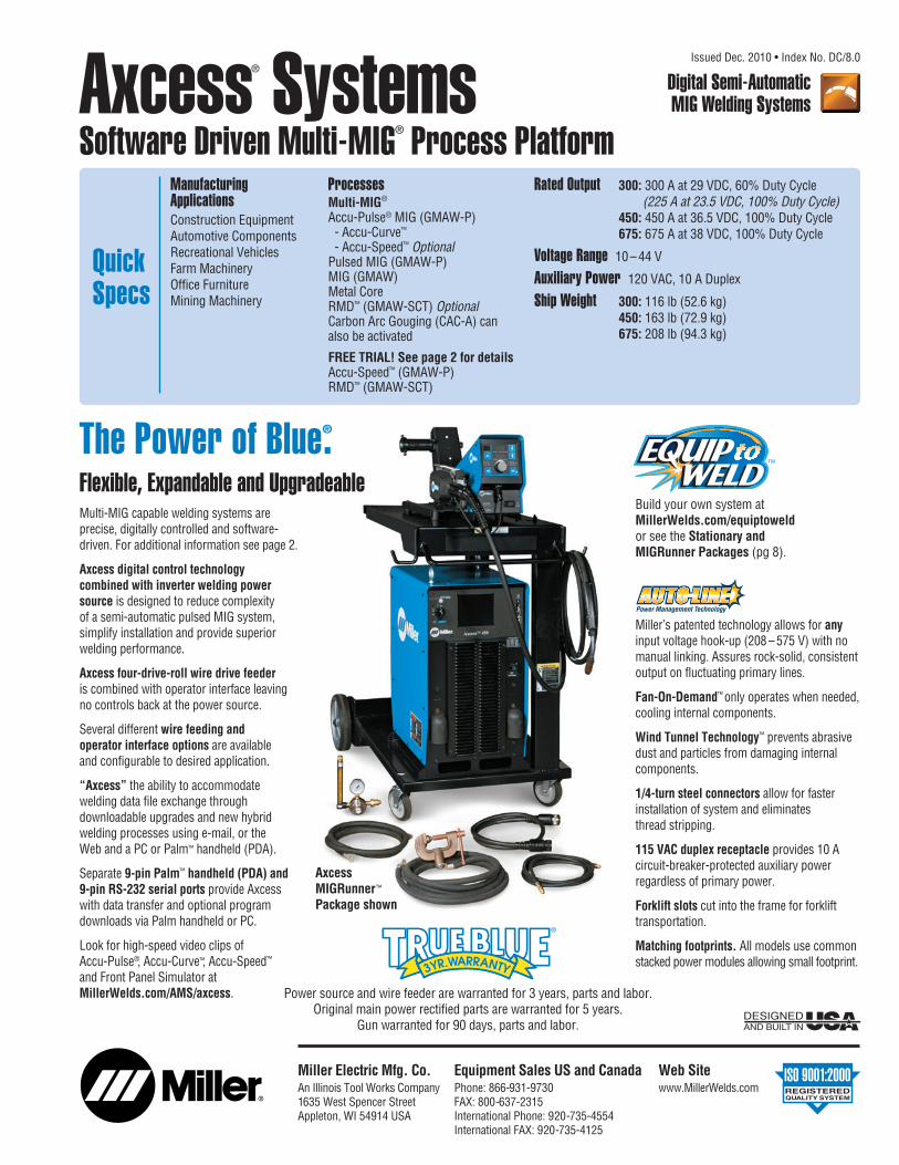
Axcess® SystemsSoftware Driven Multi-MIG® Process Platform
Digital Semi-AutomaticMIG Welding Systems
Issued Dec. 2010 • Index No. DC/8.0
The Power of Blue®.
Rated Output 300: 300 A at 29 VDC, 60% Duty Cycle(225 A at 23.5 VDC, 100% Duty Cycle)
450: 450 A at 36.5 VDC, 100% Duty Cycle675: 675 A at 38 VDC, 100% Duty Cycle
Voltage Range 10 – 44 V
Auxiliary Power 120 VAC, 10 A Duplex
Ship Weight 300: 116 lb (52.6 kg)450: 163 lb (72.9 kg)675: 208 lb (94.3 kg)
AxcessMIGRunner™
Package shown
DESIGNED AND BUILT IN
Miller’s patented technology allows for anyinput voltage hook-up (208 – 575 V) with nomanual linking. Assures rock-solid, consistentoutput on fluctuating primary lines.
Fan-On-Demand™ only operates when needed,cooling internal components.
Wind Tunnel Technology™ prevents abrasivedust and particles from damaging internalcomponents.
1/4-turn steel connectors allow for fasterinstallation of system and eliminates thread stripping.
115 VAC duplex receptacle provides 10 Acircuit-breaker-protected auxiliary powerregardless of primary power.
Forklift slots cut into the frame for forklifttransportation.
Matching footprints. All models use commonstacked power modules allowing small footprint.
Miller Electric Mfg. Co.An Illinois Tool Works Company1635 West Spencer StreetAppleton, WI 54914 USA
Web Sitewww.MillerWelds.com
Equipment Sales US and CanadaPhone: 866-931-9730FAX: 800-637-2315International Phone: 920-735-4554International FAX: 920-735-4125
Multi-MIG capable welding systems are precise, digitally controlled and software-driven. For additional information see page 2.
Axcess digital control technology combined with inverter welding powersource is designed to reduce complexity of a semi-automatic pulsed MIG system,simplify installation and provide superiorwelding performance.
Axcess four-drive-roll wire drive feederis combined with operator interface leaving no controls back at the power source.
Several different wire feeding and operator interface options are available and configurable to desired application.
“Axcess” the ability to accommodate welding data file exchange throughdownloadable upgrades and new hybrid welding processes using e-mail, or the Web and a PC or Palm™ handheld (PDA).
Separate 9-pin Palm™ handheld (PDA) and 9-pin RS-232 serial ports provide Axcess with data transfer and optional programdownloads via Palm handheld or PC.
Look for high-speed video clips of Accu-Pulse®, Accu-Curve™, Accu-Speed™
and Front Panel Simulator atMillerWelds.com/AMS/axcess.
Flexible, Expandable and UpgradeableBuild your own system atMillerWelds.com/equiptoweldor see the Stationary andMIGRunner Packages (pg 8).
Power source and wire feeder are warranted for 3 years, parts and labor.Original main power rectified parts are warranted for 5 years.
Gun warranted for 90 days, parts and labor.

Features and Benefits
2
SOFTWARE (Standard)
Multi-MIG® capability Includes common carbon steel, aluminum and stainless welding programs, including patented Accu-Pulse®, Accu-Curve™ and Accu-Speed™ (optional), standard or adaptive pulse, conventional MIG and metal core programs, and RMD™ Regulated Metal Deposition (optional) using the most popular wire diameters and gas combinations.
SureStart™ Provides consistent arc starts by electronically assuring a ball is not left on the wire when welding is stopped. This provides a predictable condition for the next arc start and combines this with precisely tuned arc starting routines.
Arc Control Control offers a simple way to tailor factory pulse weld programs by adjusting the arc plasma cone to accommodate a variety of welding applications without the need for any reprogramming or changing any hardware.
Arc Adjust Allows a simple method that controls arc length for pulse processes and wetting action for RMD.
Remote/trigger program select Allows changing weld programs to take advantage of up to 8 programs of Multi-MIG welding process capabilities.
Optional Axcess-able software Accu-Speed™ and RMD™, Axcess file management system, and WaveWriter™ pulse wave shaping.
Multi-MIG® Process Capability — Through Software-Based Programs“Axcess®” the ideal welding process for any weld joint at hand. Whether you need high travel speedcombined with high deposition rates or require gaps to be filled, any combination of the availablewelding processes can be “Axcess”-ed either at the start of a welding sequence or anywhere in theweld while actually welding by using trigger or remote program select.
For a given wire-feed speed, the chart belowshows from left (hottest) to right (coolest) all the possible arc mode transfer ranges of“Axcess”-able MIG processes. This showscompatible spray gas combinations such as 90 Ar/10 CO2 (90% Argon and 10% CarbonDioxide) on steel using the same wire-feed speedand also gives an indication of puddle controlcharacteristics based on arc type selected.
Featured Welding ProcessAccu-Pulse® STANDARD on all Axcess models
The patented Accu-Pulse process allows forprecise control of the pulse arc. Accu-Pulseprovides optimum molten puddle control andhas power to increase wire feed speeds anddeposition 20 to 25% in many applications.In most cases, slightly different ratios of gasmixtures will perform well using a similarprogram and adjusting arc length or theappropriate arc control for the selected process.Contact Miller for more information on lesscommon materials and gas combinations.
Benefits (Compared to conventional pulse)Shorter arc lengths possibleBetter puddle controlMore tolerant of contact tip to work variationLess audible noiseNo arc wandering in tight cornersNarrow arc plasma columnAllows weld to fill in at toes increasing travelspeed and depositionMore tolerant of poor fit up and gaps (compared to standard pulse)Ideal for robot seam tracking applications
Accu-Pulse(CV Peak/Background)
Taught Peak VoltageTaught Background
Voltage
Voltage
CurrentCC Ramps
Fixed current beginning points
CV Peak CV PeakCV Background
Min Current Limit
CV Background
Process RMD™ RegulatedMetal Deposition (Optional)
Standard Spray
Pulsed Spray
Accu-Pulse®
Accu-Curve™
Accu-Speed ™ (Optional)
StandardShortCircuit
Flat/Horizontal All Position Performance Thin Materials/Gap FillingWeld Puddle
Control
Note: To achieve optimum performance, 4/0 welding power secondary cable is recommended and the suppliedwork-sense lead must be connected as close to arc as possible.
Accu-Curve™ STANDARD on all Axcess models (see note below)
Accu-Curve is a variation of the Accu-Pulse process. The transitions from peaks to background voltageare “curved”. The curved transitions provide a “softer” feel without sacrificing the tight arc lengths thatallow for better puddle control and have become the hallmark of the Accu-Pulse process. Note: Accu-Curve can be added to existing Axcess systems for FREE by updating code online atMillerWelds.com/AMS/axcess. Requires Palm handheld or PC to transfer code from web site download to Axcess.
Benefits“Softer” arc feel than Accu-PulseAllows tight arc lengths and better puddle control
FREE Hour Trial of Accu-Speed™ and RMD™ with Every New Axcess Power Supply161616
3
Accu-Speed™
Field #300 719 For Palm (Required Palm handheld with data card slot is NOT included.)Field #300 720 For PC (PC-based emulator and cable are NOT included.)Note: Serial # must be provided for field installation. Factory-installed software can be ordered as a combo-number option with power supply. See power source stock number listings on page 8.
Accu-Speed is a variation of the Accu-Pulse process and was developed for the type of arcs neededin automated welding applications. Accu-Speed has a tighter driving arc that can be directed into the joint, yet still remains stable at the higher travel speeds used in automated welding. In general, Accu-Speed has lower average voltage and amperage when compared to Accu-Pulse which makes itideal when welding out of position in the manual mode. Note: Palm handheld or PC version of File Manager required for field option installation. Field kit includes cable for connecting to Axcess.
BenefitsUp to 20% greater travel speed than Accu-PulseLower average voltage/amperage than Accu-PulseTight, driving arcRemains stable at higher travel speeds
Optional Software-Based Welding Processes
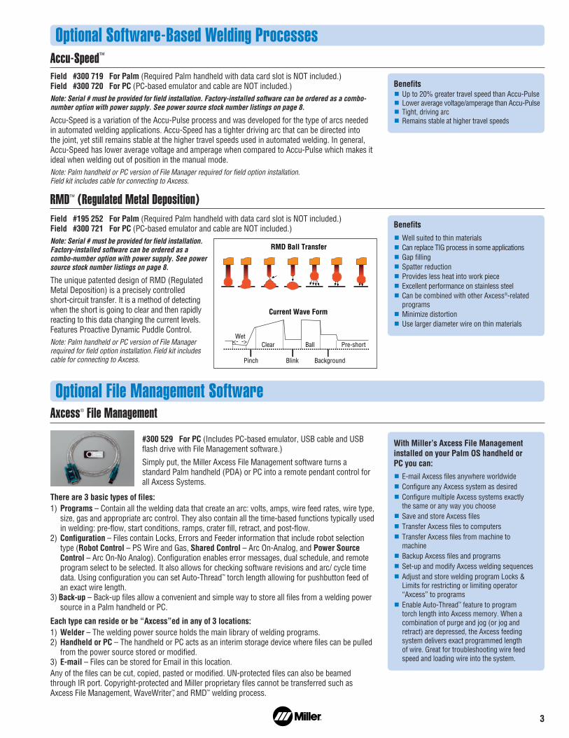
RMD™ (Regulated Metal Deposition)Field #195 252 For Palm (Required Palm handheld with data card slot is NOT included.)Field #300 721 For PC (PC-based emulator and cable are NOT included.)Note: Serial # must be provided for field installation.Factory-installed software can be ordered as acombo-number option with power supply. See powersource stock number listings on page 8.
The unique patented design of RMD (RegulatedMetal Deposition) is a precisely controlled short-circuit transfer. It is a method of detectingwhen the short is going to clear and then rapidlyreacting to this data changing the current levels.Features Proactive Dynamic Puddle Control.Note: Palm handheld or PC version of File Managerrequired for field option installation. Field kit includescable for connecting to Axcess.
BenefitsWell suited to thin materialsCan replace TIG process in some applicationsGap fillingSpatter reductionProvides less heat into work pieceExcellent performance on stainless steelCan be combined with other Axcess®-relatedprogramsMinimize distortionUse larger diameter wire on thin materials
Current Wave Form
RMD Ball Transfer
Wet<- ->
Pinch
Clear
Blink
Ball
Background
Pre-short
With Miller’s Axcess File Managementinstalled on your Palm OS handheld or PC you can:
E-mail Axcess files anywhere worldwideConfigure any Axcess system as desiredConfigure multiple Axcess systems exactly the same or any way you chooseSave and store Axcess filesTransfer Axcess files to computersTransfer Axcess files from machine tomachineBackup Axcess files and programs Set-up and modify Axcess welding sequencesAdjust and store welding program Locks &Limits for restricting or limiting operator“Axcess” to programsEnable Auto-Thread™ feature to program torch length into Axcess memory. When acombination of purge and jog (or jog andretract) are depressed, the Axcess feedingsystem delivers exact programmed length of wire. Great for troubleshooting wire feedspeed and loading wire into the system.
Optional File Management Software
#300 529 For PC (Includes PC-based emulator, USB cable and USBflash drive with File Management software.)
Simply put, the Miller Axcess File Management software turns astandard Palm handheld (PDA) or PC into a remote pendant control forall Axcess Systems.
There are 3 basic types of files:1) Programs – Contain all the welding data that create an arc: volts, amps, wire feed rates, wire type,
size, gas and appropriate arc control. They also contain all the time-based functions typically usedin welding: pre-flow, start conditions, ramps, crater fill, retract, and post-flow.
2) Configuration – Files contain Locks, Errors and Feeder information that include robot selectiontype (Robot Control – PS Wire and Gas, Shared Control – Arc On-Analog, and Power SourceControl – Arc On-No Analog). Configuration enables error messages, dual schedule, and remoteprogram select to be selected. It also allows for checking software revisions and arc/ cycle timedata. Using configuration you can set Auto-Thread™ torch length allowing for pushbutton feed ofan exact wire length.
3) Back-up – Back-up files allow a convenient and simple way to store all files from a welding powersource in a Palm handheld or PC.
Each type can reside or be “Axcess”ed in any of 3 locations:1) Welder – The welding power source holds the main library of welding programs.2) Handheld or PC – The handheld or PC acts as an interim storage device where files can be pulled
from the power source stored or modified.3) E-mail – Files can be stored for Email in this location.Any of the files can be cut, copied, pasted or modified. UN-protected files can also be beamedthrough IR port. Copyright-protected and Miller proprietary files cannot be transferred such asAxcess File Management, WaveWriter™, and RMD™ welding process.
Axcess® File Management

4
AND
The Axcess platform is designed to provide multiple wire feeding configurations suited to the unique needs of modern manufacturing applications andindustries. It utilizes many common components to minimize both part and maintenance complexity. All motors operate on 40 VDC provided by theAxcess power supply and have a wire feed speed range of 50–1400 inches per minute. A common operator interface is used on all (see page 6).
Power Source Specifications (Subject to change without notice.)
Typical Installations (Semi-Automatic Pulsed MIG or Conventional MIG)
Model
Axcess300
Axcess450
Axcess675
Rated Output
300 A at 29 VDC,60% Duty Cycle(225 A at 25.3 VDC,100% Duty Cycle)
450 A at 36.5 VDC,100% Duty Cycle
675 A at 44 VDC,100% Duty Cycle
VoltageRange
10 – 44 V
10 – 44 V
10 – 44 V
AmperageRange
5 – 400 A
5 – 600 A
5 – 900 A
Max. Open-Circuit Voltage
80 VDC
80 VDC
80 VDC
Dimensions
300 H: 23 in (584 mm)450 H: 31 in (787 mm)675 H: 39 in (991 mm)
W: 17 in (432 mm)D: 22-1/2 in (572 mm)
NetWeight
116 lb(52.6 kg)
163 lb(73.9 kg)
208 lb(94.3 kg)
Standard Installation
ROI Option InstallationAllows feeder motor drive to be placed away frompower supply and operatorinterface. Ideal for fixedautomation applications and updating or replacingequipment on booms orother applications whereseparate location of powersource, ROI, and wire drive motor is desirable.
A typical bench/sled feederinstallation. For use when the feeder is placed on thepower supply, a bench oran optional cart.
*Custom cable lengths are available through Equip to Weld™ in 5 ft increments up to 50 ft and 10 ft increments up to 100 ft.**This is the wire feed speed range while using MIG. With Pulsed MIG, the wire feed speed range may be more limited.
Model
AxcessBench/SledFeeder
GasValve
Included
Type ofInput Power
40 VDC (fromAxcess)
Connection to Power Source
DeviceNet InterconnectingFeeder Control Cable*(Order separately)
Wire Feed Speed Range**
50 –1400 IPM (1.3–35.56 MPM)
Dual FeederDimensions
H: 15 in (381 mm)W: 19 in (483 mm)D: 34 in (863 mm)
Single Feeder Dimensions
H: 14-1/2 in (368 mm)W: 12-1/2 in (318 mm)D: 27 in (686 mm)
Wire DiameterRange
.035 – 3/32 in (0.9 –2.4 mm)
Ship Weight
Single Feeder49 lb (22 kg)Dual Feeder124 lb (56 kg)
Amps Input at Rated Output, 50/60 Hz, 3-Phase208 V 230 V 400 V 460 V 575 V KVA KW
33 29.7 16.9 14.6 11.6 11.7 11.2
— 60 33.7 28.8 22.8 23.8 22.9
— 89.7 — 43.7 34.8 35.7 34.4
Certified by Canadian Standards Association to both the Canadian and U.S. Standards.
Wire Feeder OptionsAxcess Single Feeder #195 182Axcess Dual Feeder #195 325Feeder is designed specifically for Axcess. Provides single-range control of 50–1400 inches per minute. Dual-wire modelprovides the same functionality as single-wire version, but isideal when two different wire types need to be available at thesame time. Digitally communicates with Axcess power sourcevia DeviceNet Interconnecting Feeder Control Cable.
Wire feeders do NOTinclude drive rolls orrequired DeviceNetInterconnectingFeeder Control Cable.These must beordered separately.
SingleFeeder
Dual Feeder
DeviceNet InterconnectingFeeder Control Cable*5 ft (1.5 m) #242 209 00510 ft (3 m) #242 209 01025 ft (7.6 m) #242 209 02550 ft (15.2 m) #242 209 050
Motor Control Cable*20 ft (6.1 m) #242 395 02030 ft (9 m) #242 395 03050 ft (15.2 m) #242 395 050
Axcess Power Source ROI (Remote Operator Interface)
AA-40GB Wire Drive Motor Assembly(Drive rolls must be ordered separately.)
Gun (must be ordered
separately.)
DeviceNet InterconnectingFeeder Control Cable*5 ft (1.5 m) #242 209 00510 ft (3 m) #242 209 01025 ft (7.6 m) #242 209 02550 ft (15.2 m) #242 209 050
Axcess Power Source Axcess Wire Feeder (Drive rolls must be ordered separately.)
Gun (comes
with feeder.)
Feeder Base#195 369 (see page 7)
Boom RetrofitApplications
21-ft Trigger Control Cable #300 129
Flexible Mounting Options
21
3 41
1
2
AND AND
*Custom cable lengthsare available throughEquip to Weld™ in 5 ftincrements up to 50 ftand 10 ft incrementsup to 100 ft.

5
Model
AA-40GB
GasValve
Includedandenclosed
Type of InputPower
40 VDC (from Axcess)
Connection to Power Source
Motor Control Cable*(Order separately)
Wire Feed Speed Range**
50 –1400 IPM (1.3 – 35.56 MPM)
AA-40GBDimensions
H: 8 in (203 mm)W: 12 in (305 mm)D: 10 in (254 mm)
Wire DiameterRange
.035 – 3/32 in (0.9 –1.6 mm)
ShipWeight
23 lb (10.4 kg)
*Custom cable lengths are available through Equip to Weld™ in 5 ft increments up to 50 ft and 10 ft increments up to 100 ft.**This is the wire feed speed range while using MIG. With Pulsed MIG, the wire feed speed range may be more limited.
*Custom cable lengths are available through Equip to Weld™ in 5 ft increments up to 50 ft and 10 ft increments up to 100 ft.
Model
ROI
Type of Input Power
Supplied from power source
Connection to Motor
Motor Control Cable*(Order separately)
Connection to Power Source
DeviceNet InterconnectingFeeder Control Cable*(Order separately)
Single ROI Dimensions
H: 13 in (330 mm)W: 7 in (178 mm)D: 7 in (178 mm)
Dual ROI Dimensions
H: 13 in (330 mm)W: 9 in (229 mm)D: 10 in (254 mm)
Ship Weight
Single ROI12 lb (5.4 kg)Dual ROI15 lb (6.8 kg)
ROI (Remote Operator Interface) Options
Wire Drive Motor Assembly Options (To be used with Remote Operator Interface.)
Single ROI #195 238Dual ROI #195 433The ROI allows the Axcess power supply, wiredrive motor assembly and operator interface (ROI)to be located in three separate places. This isdesirable for mounting to custom jibs, booms orother extended-reach applications. Since an ROIsystem can incorporate separate componentsproviding the most flexibility for custom appli -cations, it’s an ideal way to obtain the manybenefits of the Axcess while retaining an existingboom or other structural asset. The dual-wire ROIprovides the same functionality as the single,but controls two separate wire drive motorassemblies. Four programs are available per side.Note: For non-Miller boom and jib mounting, see ROI installation diagram on page 4 and select desiredcable lengths.
Auto ROI #195 239*(Contact Applications for assistance at 920-954-3809 prior to any new installation.)The Auto ROI is to be used with an Axcesspower supply with the E-Stop option. Providesfunctionality of the ROI, but replaces sequenceand trigger functions with two programmableinputs and outputs. To be used in simplededicated/fixed/hard automation applications.Features arc established output. Includes 30 ftcable for wiring to other external devices.*Requires Axcess power supply with E-Stop functionoption. E-Stop is not intended for continuousinterruption applications. Axcess systems requireapproximately 30 seconds to reboot or come backonline after recovering from an E-Stop condition.Note: For non-Miller boom and jib mounting, see ROI installation diagram on page 4 and select desiredcable lengths.
Axcess® ROI Swingarc™ Boom-Mounted Wire Feeders#951 383 8 ft (2.4 m) Single-Wire#951 384 12 ft (3.7 m) Single-Wire#951 385 16 ft (4.9 m) Single-Wire#951 386 8 ft (2.4 m) Dual-Wire#951 387 12 ft (3.7 m) Dual-Wire#951 388 16 ft (4.9 m) Dual-WireSwingarc boom-mounted semiautomatic wirefeeders bring an extra dimension of flexibilityand efficiency to high-production MIG weldingstations. You get an effective solution thatmaximizes output, especially when dealing withlarge weldments and hard-to-reach places.
Dual Swingarc Retrofit Kit #300 032Kit is required when replacing motors on olderMiller Dual 60 Series Swingarc booms. Providesall of the Axcess benefits, but maintains existingdual-boom hardware.
21-ft Trigger Control Cable #300 129Required when retrofitting non-Miller boomswith an ROI option.
AA-40GB Wire Drive Motor Assembly #195 426 Left-Hand Drive#195 515 Right-Hand DriveThe AA-40GB Wire Drive Motor Assembly withOCP (Over Current Protection) is an improvedversion of the AA-40G. The motor control cablenow mounts directly to the gas box, reducingstrain on the tachometer wires. OCP provides
another layer of protection in the event a cable is damaged or shorted, reducing downtime and motor damage. Motors include a 50 ft volt-sense cable.
Note: Wire drive motor assemblies do NOT includedrive rolls or required Motor Control Cable. Thesemust be ordered separately. Left- and right-hand drivesare determined by facing the wire feed gun outlet.
Pipe post NOT included. Must be ordered separately. • 4 ft Pipe Post with
18 in Base #149 838• 6 ft Pipe Post with
18 in Base #149 839
DeviceNet Interconnecting Cable NOT included (required, order separately).
MIG gun now includedwith feeder.
Single ROIDual ROI
ROI does NOT include AA-40GB Wire Drive Motor Assembly, Motor Control Cable or DeviceNet Interconnecting Feeder Control Cable. These must be ordered separately.
Auto ROI back panel showing connections for input and output signals.
3
4

6
1 3
2
MILLER ELECTRIC MFG. CO., APPLETON, WI
MADE IN
64
5
Control Panels
1.Power Switch2.Handheld
RS-232 Port3.PC-Communication
RS-232 Port 4.115 VAC, 10 A
Duplex Receptacle5.Circuit Breakers6.Network Feeder
Connector
1. Voltage/Arc AdjustDisplay Meter
2. Program Display3. Program # Select4. Process Setup Button5. Control Knob6. Trigger Receptacle7. On/Off Button8. Voltage Setup Button9. Wire Speed Setup
Button10. Wire Speed/Amperage
Display Meter11. Feeder Setup Button12. Jog/Purge Switch
Front Panel
Rear Panel
Program
ProcessWire TypeGas Type
Volts Time Arc Adjust
WFS Amps Arc Ctl
Process Set Up Adjust Feeder Set Up
Trigger HoldTrigger ControlSequence
5
4
7
6
321
89
11
12
10
Single Axcess Feeder and Remote Operator Interface (ROI)
CapabilitiesDual Schedule — Toggle between twosettings using a single wire.
4T — When trigger is released, output willoperate at different ranges.
Trigger Program Select (TPS) — Providesthe ability to “Axcess” any of the Multi-MIG®
processes or any of the eight active programs.
Trigger Dual Schedule (TDS) — When activatedallow selection between predetermined programpairs (e.g. 1,2 – 3,4 – 5,6 – 7,8).
Trigger Hold (TH) — When activated, allowsgun trigger release and continuous welding untiltrigger is pulled again.
Carbon Arc Gouging (CAC-A)—Can be activated.
Wire Size
.023/.025 in (0.6 mm) #151 024 — — —
.030 in (0.8 mm) #151 025 — — —
.035 in (0.9 mm) #151 026 #243 233 #151 052 —
.040 in (1.0 mm) #161 190 — — —
.045 in (1.1/1.2 mm) #151 027 #243 234* #151 053 #151 070
.052 in (1.3/1.4 mm) #151 028 #151 038 #151 054 #151 0711/16 in (1.6 mm) #151 029 #243 235 #151 055 #151 072.068/.072 in (1.8 mm) — — #151 056 —5/64 in (2.0 mm) — #151 040 #151 057 #151 0733/32 in (2.4 mm) — #151 041 #151 058 #151 0747/64 in (2.8 mm) — #151 042 #151 059 #151 0751/8 in (3.2 mm) — #151 043** #151 060** #151 076**
Drive Roll Kits and Guides (Order from Miller Service Parts.)
Drive Roll Kits Select drive roll kits from chart below according to type and wire size being used.Drive roll kits include 4 drive rolls, the necessary guides and feature an anti-wear sleeve for inlet guide.
*Accommodates .045 and .047 (3/64 in) wire. **May require a low-speed, wire-feed drive-roll option.
“V” groove for hard wire
“U” groove for softwire or soft-shelled
cored wires
“V” knurled forhard-shelled cored wires
“U” cogged for extremely soft wire or
soft-shelled cored wires(i.e., hard facing types)
IntermediateWire Size Inlet Guide Guide.035 in (0.9 mm) #221 912 #242 417.047 in (1.2 mm) #221 912 #205 9361/16 in (1.6 mm) #221 912 #205 937
Nylon Wire Guides for Feeding Aluminum Wire
IntermediateWire Size Inlet Guide Guide.023 –.040 in #150 993 #149 518(0.6 –1.0 mm).045 –.052 in #150 994 #149 519(1.1 –1.4 mm)1/16 – 5/64 in #150 995 #149 520(1.6 – 2 mm)3/32 –7/64 in #150 996 #149 521(2.4 – 2.8 mm)1/8 in (3.2 mm) #150 997 #149 522
Note: “U” groove drive rolls are recommended whenfeeding aluminum wire.
Wire Guides
Crater: 0.1– 5 sPostflow: 0.1– 5 s
Sequence (in seconds)Preflow: 0.1– 5 sStart Power: 0.1– 5 s
Arc Adjust — Arc length (Trim)
Arc Control — Arc force or focus (SharpArc®)
Process Selection — Accu-Pulse®, Pulsed MIG,MIG, Metal Core, RMD™ (Optional)

7
Consulting ServicesField Application Support #195 480Axcess systems may require factory-trainedtechnical support depending on the complexityof the application and the local availabilityand capability of qualified welding engineers.You should contact the factory if there arequestions. Factory support is available at aflat rate of $1250.00 per day plus expenseswhen planned and ordered more than 10 daysin advance. Rates and avail ability of ourtechnical specialists with less than 10 daynotice are considerably more. Rates arebased on a 10-hour day including travel. One day minimum.
DeviceNet Interconnecting Feeder Control Cables #242 209 005 5 ft (1.5 m)#242 209 010 10 ft (3 m)#242 209 025 25 ft (7.6 m)#242 209 050 50 ft (15.2 m)These specially designed EMI (Electrical MagneticInterference) protected and shielded feedercontrol cables are required, but not includedwith Axcess feeders or ROI. Determine lengthneeded and order separately. Note: Custom cable lengths are available throughEquip to Weld™ in 5 ft increments up to 50 ft and 10 ft increments up to 100 ft.
Motor Control Cables #242 395 020 20 ft (6.1 m)#242 395 030 30 ft (9 m)#242 395 050 50 ft (15.2 m)Includes overmolded connections on high-flexcables for optimal service life.Note: Custom cable lengths are available throughEquip to Weld™ in 5 ft increments from 5 to 50 ft, and 10 ft increments from 60 to 100 ft.
Volt-Sense Work Cable, 50 ft #242 212 050Note: Custom cable lengths are available throughEquip to Weld™ in 5 ft increments up to 50 ft and 10 ft increments up to 100 ft.
Running Gear CylinderRack #300 408For Axcess 300 and 450models. Holds two largegas cylinders and hasgun cable hangers and aconsumable drawer infront for easy access. Aconvenient handle allowsthe cart to be pulled
easily through doorways. System componentsincluding power source, single- or dual feeders,and Coolmate™ V3 can be mounted to the cartand secured.
Industrial MIG 4/0 Kit #300 390Consists of Smith®
regulator/flowmeterwith 10 ft (3 m)
gas hose, 10 ft (3 m). 4/0 feeder weld cable with lugs, and 15 ft (4.6 m) work cable with600-amp C-clamp.
Axcess® Feeder Baseand Spool Support#195 369Sheet metal construction.Allows mounting of AA-40GB motor (if desired) when usingROI option or when
using an Auto-Axcess with Smart Cable adapter.
Hub and SpindleAssembly #072 094
Spindle Support#092 989
Wire Reel Assembly #108 008
Spool Covers
#057 607
Reel Covers #058 256For 60 lb (27 kg) coil. Helps to protect the weld ingwire from dust and other contaminants.Note: Reel and Spool Covers cannot be installed if the wire drive assembly is in a rotated position.
Turntable Assembly #146 236Allows rotation of the feeder as the operatorchanges work positions. Reduces strain andbending on the gun cable.
Hanging Bail (Electrically Isolated) #058 435Used for suspending feeder over work area.
Wire Straightener #141 580 For .035–.045 in (0.9–1.1 mm) wire.#141 581 For 1/16–1/8 in (1.6–3.2 mm) wire.Helps reduce the cast in wire to improve wirefeeding performance and increase the servicelife of the gun liner and contact tip.
Dual Schedule SwitchesDSS-8 #079 693A 15 ft, two-position
trigger switch which attaches to the gun handleand is used in place of the standard trigger fordual scheduling.
Adapter Cord #157 364Required for use with DSS-8. 1ft, Y trigger cable that connects DSS switch and control boxto the gun.
DSS-9M #041 793A 15 ft, two-position slide switch
which attaches to the gun handle and is used to select the desired welding condition for dualschedule purposes. The gun trigger operates asa standard trigger.
Coolant SystemsFor more information, see the Miller CoolantSystems literature sheet, Index No. AY/7.2.
Coolmate™ 3#043 007 115 VAC#043 008 230 VACFor use with water-cooled torches rated up to600 amps. Unique paddle-wheel indicator,external filter and easy-fill spout.
Coolmate™ V3 #043 009 115 VACFor use with water-cooled torches rated up to500 amps. Vertical design conveniently mountsto Miller cylinder rack in place of one cylinder.
Coolmate™ 4 #042 288 115 VACFor use with water-cooled torches rated up to600 amps. Tough molded polyethylene casewith carrying handle.
Low Conductivity Coolant #043 810Sold in cases of four 1-gallon recyclable plasticbottles. Miller coolants contain a base ofethylene glycol and deionized water to protectagainst freezing to -37˚F (-38˚C) or boiling to227˚F (108˚C). Also contains a compound thatresists algae growth.
Genuine Miller Accessories
Shown with AA-40GB.
Coolmate 3 Coolmate 4
Coolmate V3
SpindleSupport
Hub andSpindleAssembly

Semi-Automatic Equipment Options Stock No. Description Qty. Price
Axcess® 300 #907 150 Power source only#907 150-00-1 Power source with Accu-Speed™ software upgrade#907 150-01-1 Power source with RMD™ software upgrade
Axcess® 450 #907 152 Power source only#907 152-00-1 Power source with Accu-Speed™ software upgrade#907 152-01-1 Power source with RMD™ software upgrade
Axcess® 675 #907 154 Power source#907 154-00-1 Power source with Accu-Speed™ software upgrade
Axcess® 300 Stationary Package #951 227 Power source, bench feeder, Bernard® Q-Gun™, and Industrial MIG 4/0 kitAxcess® 300 MIGRunner™ Package #951 226 Power source, bench feeder, Bernard® Q-Gun™, Industrial MIG 4/0 kit and
running gear/cylinder rackAxcess® 450 Stationary Package #951 229 Power source, bench feeder, Bernard® Q-Gun™, and Industrial MIG 4/0 kit
Axcess® 450 MIGRunner™ Package #951 228 Power source, bench feeder, Bernard® Q-Gun™, Industrial MIG 4/0 kit and running gear/cylinder rack
Note: Other power sources are available. Consult factory at 1-920-954-3809 for power sources with E-Stop option.
Wire Feeder Options (see page 4)Axcess® Single Feeder #195 182 Bench/skid feeder — order DeviceNet Interconnecting Feeder Control Cable separatelyAxcess® Dual Feeder #195 325 Bench/skid feeder — order DeviceNet Interconnecting Feeder Control Cable separately
ROI Options (see page 5)Single ROI #195 238 See page 4 for connection diagram and required cablesDual ROI #195 433 See page 4 for connection diagram and required cablesAuto ROI (see note above) #195 239 See page 4 for connection diagram and required cables.
Requires power source with E-Stop option — consult factory at 1-920-954-3809Axcess® ROI Swingarc™ Boom See page 5 for various modelsDual Swingarc™ Retrofit Kit #300 032 Required when replacing motors on older Dual 60 Series Swingarc booms
Wire Drive Assembly Opt. (see page 5)AA-40GB Wire Drive Motor Assembly New-style wire drive assembly. See page 4 for connection diagram and required cables
Control Cables (see page 7) See page 4 for connection diagram and required cables
Optional Software-Based Welding ProcessesAccu-Speed™ #300 719 For Palm. Field (required Palm™ handheld is NOT included)
#300 720 For PC. Field (required PC-based emulator and cable are NOT included)RMD™ (Regulated Metal Deposition) #195 252 For Palm. Field (required Palm™ handheld is NOT included)
#300 721 For PC. Field (required PC-based emulator and cable are NOT included)
Optional File Management Software Axcess® File Management #300 529 For PC. File management software (PC-based emulator is included)WaveWriter™ Wave Shaping Consult factory For PC. File management software with wave shaping (PC-based emulator is included)
AccessoriesDrive Roll Kit (Required) See page 6Inlet/Intermediate Guides See page 6Field Application Support #195 480 One day minimum, not subject to discount. See page 7Volt-Sense Work Cable #242 212 050 50 ft (15.2 m) cable. Custom cable lengths are available through Equip to Weld™
in 5 ft increments up to 50 ft and 10 ft increments up to 100 ftRunning Gear Cylinder Rack #300 408 Holds two cylinders, cooler, machine and feederIndustrial MIG 4/0 Kit #300 390 Includes Smith regulator/flowmeter with 10 ft (3 m) gas hose, 10 ft (3 m) 4/0 feeder
weld cable with lugs, and 15 ft (4.6 m) work cable with 600-amp C-clampAxcess® Feeder Base and Spool Support #195 369 Allows mounting of AA-40GB motor when using ROI optionHub and Spindle Assembly #072 094Spindle Support #092 989Additional Feeder Accessories See page 7Dual Schedule Switches See page 7Coolant Systems See page 7
Date: Total Quoted Price
Litho in USA
Distributed by:
Ordering Information