AUTOMATIC FOUR-POLE CIRCUIT-BREAKERS … Rev.00... · This document is intellectual property of...
22
GLOBAL STANDARD Page 1 of 22 AUTOMATIC FOUR-POLE CIRCUIT-BREAKERS WITH 40 A ÷ 630 A RATED CURRENT FOR SECONDARY SUBSTATIONS GSCL003 Rev. 0 20/06/2016 AUTOMATIC FOUR-POLE CIRCUIT-BREAKERS WITH 40 A ÷ 630 A RATED CURRENT FOR SECONDARY SUBSTATIONS Countries’ I&N Elaborated by Iberia J. Gonzalez Italy M. Neri Romania V. Obrejan This document is intellectual property of Enel Spa; reproduction or distribution of its contents in any way or by any means whatsoever is subject to the prior approval of the above mentioned company which will safeguard its rights under the civil and penal codes. This document is for Internal Use. Elaborated by Verified by Approved by Solution Development Center M. Neri L. Giansante I. Gentilini Global I&N – NT/NCS - N. Cammalleri G. Egea Brufau F. Giammanco Revision Type of modification 00 First edition –
Transcript of AUTOMATIC FOUR-POLE CIRCUIT-BREAKERS … Rev.00... · This document is intellectual property of...
GLOBAL STANDARD
Page 1 of 22
AUTOMATIC FOUR-POLE CIRCUIT-BREAKERS WITH 40 A ÷ 630 A RATED CURRENT
FOR SECONDARY SUBSTATIONS
GSCL003 Rev. 0
20/06/2016
AUTOMATIC FOUR-POLE CIRCUIT-BREAKERS WITH 40 A ÷ 630 A RATED CURRENT FOR SECONDARY SUBSTATIONS
Countries’ I&N Elaborated by
Iberia J. Gonzalez
Italy M. Neri
Romania V. Obrejan
This document is intellectual property of Enel Spa; reproduction or distribution of its contents in any way or by any means whatsoever is subject to the prior approval of the above mentioned company which will safeguard its rights under the civil and penal codes. This document is for Internal Use.
Elaborated by Verified by Approved by
Solution Development Center M. Neri L. Giansante I. Gentilini
Global I&N – NT/NCS - N. Cammalleri G. Egea Brufau F. Giammanco
Revision Type of modification 00 First edition –

GLOBAL STANDARD
Page 2 of 22
AUTOMATIC FOUR-POLE CIRCUIT-BREAKERS WITH 40 A ÷ 630 A RATED CURRENT
FOR SECONDARY SUBSTATIONS
GSCL003 Rev. 0
20/06/2016
INDEX
1. SCOPE 3
2. FIELD OF APPLICATION 3
3. COMPONENT IDENTIFICATION 3
4. REFERENCE LAWS AND STANDARDS 3
5. IDENTIFICATION COMPONENTS 5
6. UNIT MEASUREMENT 7
7. IDENTIFICATION COMPONENTS 8
8. TECHNICAL SPECIFICATIONS 8 9. CONSTRUCTION CHARACTERISTICS 14
10. SUPPLY REQUIREMENTS 21
GLOBAL STANDARD
Page 3 of 22
AUTOMATIC FOUR-POLE CIRCUIT-BREAKERS WITH 40 A ÷ 630 A RATED CURRENT
FOR SECONDARY SUBSTATIONS
GSCL003 Rev. 0
20/06/2016
1. SCOPE
The scope of this document is to provide the technical requirements for the supply of automatic
circuit-breakers for use in Low Voltage distribution networks with rated currents of 40 A - 80 A –
120 A – 180 A - 250 A (with 10 kA pole mounted transformers and 25 kA for substations rated
short-circuit breaking capacities) – 350 A and 630 A (with 25 kA rated short-circuit breaking
capacities) of the Enel Group Distribution companies listed below:
• Endesa Distribución Eléctrica (Spain)
• Enel Distributie Banat (Romania)
• Enel Distributie Dobrogea (Romania)
• Enel Distributie Muntenia (Romania)
• Enel Distribuzione (Italy)
Some requirements are applicable only to one or more companies. Therefore, depending on the
destination, the supplied equipment shall comply with these specific requirements.
2. FIELD OF APPLICATION
These requirements apply to automatic four-pole circuit-breakers used in Low Voltage distribution
networks and installed in secondary substations and pole-mounted transformers (PMT).
The document is used in purchase tenders and for conformity and quality technical checks.
3. COMPONENT IDENTIFICATION
This specification refers to the family of four-pole circuit-breakers with rated current from 40 A to
630 A for secondary substations identified as follows:
4. REFERENCE LAWS AND STANDARDS
4.1 Laws
4.1.1 Italy – Romania - Spain
• Directive 2006/95/EC of the European Parliament and of the Council of 12
December 2006.
• Directive 2004/108/EC electromagnetic compatibility.
• Directive 2014/30/UE of the European Parliament - 26.2.14.
GLOBAL STANDARD
Page 4 of 22
AUTOMATIC FOUR-POLE CIRCUIT-BREAKERS WITH 40 A ÷ 630 A RATED CURRENT
FOR SECONDARY SUBSTATIONS
GSCL003 Rev. 0
20/06/2016
4.1.2 Italy
• D.Lgs n. 81 of the 9th of April 2008 and subsequent modifications.
• Decreto Ministeriale Ambiente n. 20 – 25 Gen. 2011
4.1.3 Romania
• Legea securităţii şi sănătăţii în muncă nr.319/2006, cu modificările şi completările
ulterioare.
• Ordonanţa de Urgenţă nr. 195/22.12.2005 privind protecţia mediului, cu toate
modificările şi completările în vigoare.
• Legea nr. 211/25.11.2011 privind regimul deşeurilor.
• H.G. 856/2002 privind evidenţa gestiunii deşeurilor şi pentru aprobarea listei
cuprinzând deşeurile, inclusiv deşeurile periculoase, completată de HG 210/2007.
• H.G. 1037/03.11.2010 privind deşeurile de echipamente electrice şi electronice.
• H.G. nr. 1132/18.09.2008 privind regimul bateriilor şi acumulatorilor şi al deşeurilor
de baterii şi acumulatori.
4.1.4 Spain
• R.D. 337/2014, de 9 de mayo, por el que se aprueban el Reglamento sobre
condiciones técnicas y garantías de seguridad en instalaciones eléctricas de alta
tensión y sus Instrucciones Técnicas Complementarias ITC-RAT 01 a 23.
• R.D. 614/2001, de 8 de junio, sobre disposiciones mínimas para la protección de la
salud y seguridad de los trabajadores frente al riesgo eléctrico.
• Real Decreto 842/2002, de 2 de agosto, por el que se aprueba el Reglamento
Electrotécnico para Baja Tensión, con sus instrucciones técnicas complementarias
4.2 Standards
4.2.1 Common standards
The below listed reference documents shall be intended in the in-force edition at the
contract date (amendments included). Unless otherwise specified, these documents are
valid until the new editions replace them.
For Latin America destinations the reference standards are the IEC/ISO, whilst for
Europe destinations the reference standards are the correspondent European ones
(EN).

GLOBAL STANDARD
Page 5 of 22
AUTOMATIC FOUR-POLE CIRCUIT-BREAKERS WITH 40 A ÷ 630 A RATED CURRENT
FOR SECONDARY SUBSTATIONS
GSCL003 Rev. 0
20/06/2016
Standards Edition EN 60947-2 2006-08 EN 60947-1 2007-07
4.2.2 Specific standards
Unless otherwise specified, these standards are valid until the new editions replace
them.
4.2.2.1 Enel Distribuzione
Standards Revision DY3501 6 DY1053 2 DY818 4 GSCB003 0 DY3018 3 DY3023 3 EA0210 4 EA0211 5 EA0037 6 PVR001 2 PVR006 + alleg. alla N.O. PVR006 2 Packaging, transport and delivery requirements 2
5. IDENTIFICATION COMPONENTS
This specification refers to the family of four-pole circuit-breakers with rated current from 40 A to
630 A for secondary substations identified as follows:
GLOBAL STANDARD
Page 6 of 22
AUTOMATIC FOUR-POLE CIRCUIT-BREAKERS WITH 40 A ÷ 630 A RATED CURRENT
FOR SECONDARY SUBSTATIONS
GSCL003 Rev. 0
20/06/2016
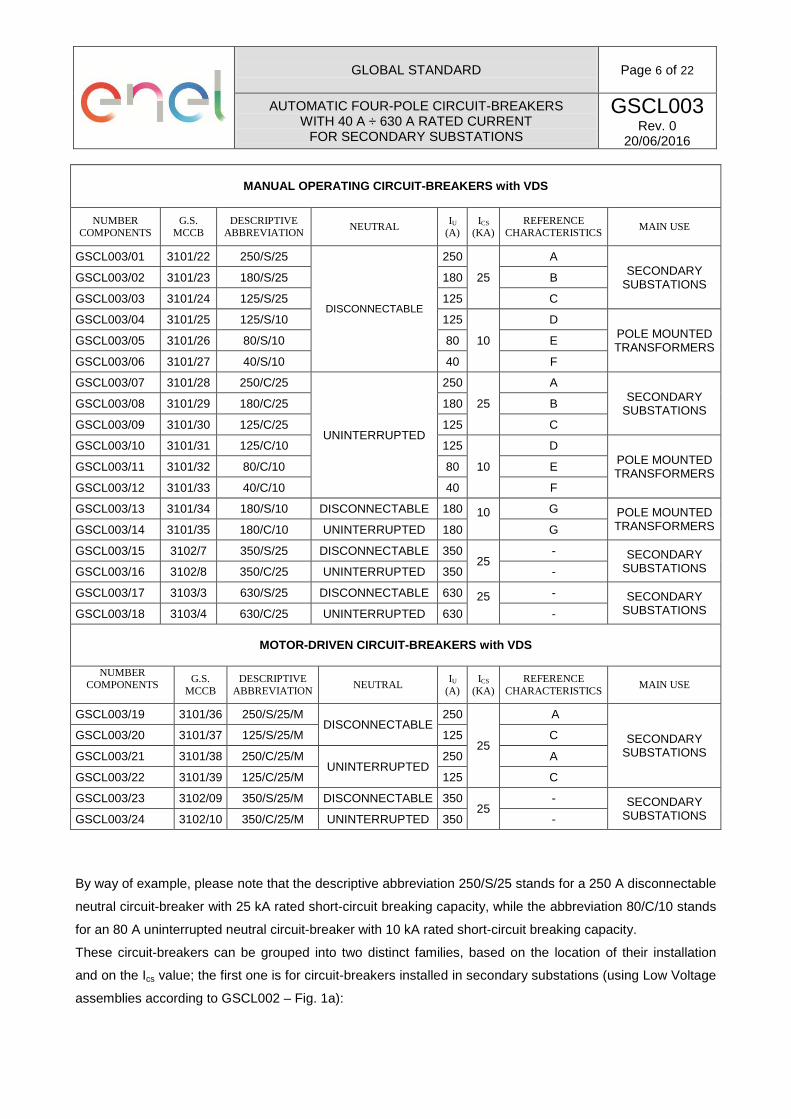
MANUAL OPERATING CIRCUIT-BREAKERS with VDS
NUMBER COMPONENTS G.S.
MCCB DESCRIPTIVE ABBREVIATION NEUTRAL IU
(A) ICS
(KA) REFERENCE
CHARACTERISTICS MAIN USE
GSCL003/01 3101/22 250/S/25
DISCONNECTABLE
250
25
A SECONDARY
SUBSTATIONS GSCL003/02 3101/23 180/S/25 180 B
GSCL003/03 3101/24 125/S/25 125 C
GSCL003/04 3101/25 125/S/10 125
10
D POLE MOUNTED TRANSFORMERS GSCL003/05 3101/26 80/S/10 80 E
GSCL003/06 3101/27 40/S/10 40 F
GSCL003/07 3101/28 250/C/25
UNINTERRUPTED
250
25
A SECONDARY
SUBSTATIONS GSCL003/08 3101/29 180/C/25 180 B
GSCL003/09 3101/30 125/C/25 125 C
GSCL003/10 3101/31 125/C/10 125
10
D POLE MOUNTED TRANSFORMERS GSCL003/11 3101/32 80/C/10 80 E
GSCL003/12 3101/33 40/C/10 40 F
GSCL003/13 3101/34 180/S/10 DISCONNECTABLE 180 10
G POLE MOUNTED TRANSFORMERS GSCL003/14 3101/35 180/C/10 UNINTERRUPTED 180 G
GSCL003/15 3102/7 350/S/25 DISCONNECTABLE 350 25
- SECONDARY SUBSTATIONS GSCL003/16 3102/8 350/C/25 UNINTERRUPTED 350 -
GSCL003/17 3103/3 630/S/25 DISCONNECTABLE 630 25
- SECONDARY SUBSTATIONS GSCL003/18 3103/4 630/C/25 UNINTERRUPTED 630 -
MOTOR-DRIVEN CIRCUIT-BREAKERS with VDS
NUMBER
COMPONENTS
G.S. MCCB DESCRIPTIVE
ABBREVIATION NEUTRAL IU (A)
ICS (KA)
REFERENCE CHARACTERISTICS MAIN USE
GSCL003/19 3101/36 250/S/25/M DISCONNECTABLE
250
25
A
SECONDARY SUBSTATIONS
GSCL003/20 3101/37 125/S/25/M 125 C
GSCL003/21 3101/38 250/C/25/M UNINTERRUPTED
250 A
GSCL003/22 3101/39 125/C/25/M 125 C
GSCL003/23 3102/09 350/S/25/M DISCONNECTABLE 350 25
- SECONDARY SUBSTATIONS GSCL003/24 3102/10 350/C/25/M UNINTERRUPTED 350 -
By way of example, please note that the descriptive abbreviation 250/S/25 stands for a 250 A disconnectable
neutral circuit-breaker with 25 kA rated short-circuit breaking capacity, while the abbreviation 80/C/10 stands
for an 80 A uninterrupted neutral circuit-breaker with 10 kA rated short-circuit breaking capacity.
These circuit-breakers can be grouped into two distinct families, based on the location of their installation
and on the Ics value; the first one is for circuit-breakers installed in secondary substations (using Low Voltage
assemblies according to GSCL002 – Fig. 1a):

GLOBAL STANDARD
Page 7 of 22
AUTOMATIC FOUR-POLE CIRCUIT-BREAKERS WITH 40 A ÷ 630 A RATED CURRENT
FOR SECONDARY SUBSTATIONS
GSCL003 Rev. 0
20/06/2016
Figure 1a
and the second one is for circuit-breakers on Pole Mounted Transformers (using type UE DY3018 – Fig. 1b
or type DY3023):
Figure 1b
6. UNIT MEASUREMENT
The circuit-breakers of this specification are managed as single units (i.e. as numbers). The following is an
example of a circuit-breaker description used in ENEL:
I N T E R R U T T O R E A U T O M A T B T 4 P 2 5 0 / C / 2 5 U E

GLOBAL STANDARD
Page 8 of 22
AUTOMATIC FOUR-POLE CIRCUIT-BREAKERS WITH 40 A ÷ 630 A RATED CURRENT
FOR SECONDARY SUBSTATIONS
GSCL003 Rev. 0
20/06/2016
7. IDENTIFICATION COMPONENTS
Serial Number Italy Romania
Iberia
Serial Components Enel Distribuz. Enel Distributie
Endesa distribucion
GSCL003/01 13 11 02 --- 6712126
GSCL003/02 13 11 03 --- 6712125
GSCL003/03 13 11 04 --- 6712124
GSCL003/04 13 11 05 --- ---
GSCL003/05 13 11 06 --- ---
GSCL003/06 13 11 07 --- ---
GSCL003/07 13 11 08 13 11 08 6712131
GSCL003/08 13 11 09 13 11 09 6712130
GSCL003/09 13 11 10 13 11 10 6712129
GSCL003/10 13 11 11 13 11 11 ---
GSCL003/11 13 11 12 13 11 12 ---
GSCL003/12 13 11 13 13 11 13 ---
GSCL003/13 13 11 14 --- ---
GSCL003/14 13 11 15 13 11 15 ---
GSCL003/15 13 11 20 --- 6712127
GSCL003/16 13 11 21 13 11 21 6712132
GSCL003/17 13 11 24 --- 6712128
GSCL003/18 13 11 25 13 11 25 6712133
GSCL003/19 13 11 16 --- 6712135
GSCL003/20 13 11 17 --- 6712134
GSCL003/21 13 11 18 13 11 18 6712138
GSCL003/22 13 11 19 13 11 19 6712137
GSCL003/23 13 11 22 --- 6712136
GSCL003/24 13 11 23 13 11 23 6712139
8. TECHNICAL SPECIFICATIONS
The circuit-breakers of this specification must observe the general requirements and the regulations enforced
by the reference documents in chapter 4.
In general, once installed the circuit breakers on the switchboard, and placed the terminal covers, the
insulation level between the active parts (phases and neutral) and earth (considering earth also any point on
the outside surface of the circuit breaker envelope) must be equal or greater than 10kV (1 minute).
The tables below reports the specific requirements that the individual circuit-breakers must observe
according to their size and installation characteristics.

GLOBAL STANDARD
Page 9 of 22
AUTOMATIC FOUR-POLE CIRCUIT-BREAKERS WITH 40 A ÷ 630 A RATED CURRENT
FOR SECONDARY SUBSTATIONS
GSCL003 Rev. 0
20/06/2016
8.1 Characteristics of circuit-breaker with 40 - 250 A rated current
REFERENCE CHARACTERISTICS A B C D E F G
Circuit-breaker type four-pole, suitable for isolation, moulded case type with
organic material enclosure without accessible metallic parts, maintenance free
Installation type vertical IP code (1) IP3X (2) Frequency (Hz) 50 Making operating system independent manual with non-removable lever
Breaking operating system independent manual with non-removable lever and with thermal and magnetic releases
Rated voltage (Ue) (V) 400 Rated insulation voltage (Ui) (V) 690 Rated impulse withstand voltage (Uimp) (kV) 8 Rated uninterrupted current at 40 °C (Iu) (A) 250 180 125 125 80 40 180 Service uninterrupted Utilization category A Rated service short-circuit breaking capacity (Ics) (kA) 25 10
Phase thermal release (1 per phase)(3) - conventional free air thermal current at 40 °C (Ith) (A) 250 180 125 125 80 40 180 - conventional non tripping current (A) 1.05 Ith - conventional tripping current (A) 1.30 Ith - maximum breaking time at 2 Ith on single pole with cool release at ambient temperature of 40 °C (min) 12 10 8 8 8 6 10
Phase magnetic release (1 per phase)(3) - current setting (Im) (A) 1250 1000 800 800 400 200 1000 - breaking time for a tripping current of 3 Im (ms) ≤ 15 - tripping current precision (%) ± 20
Neutral thermal release (3) - conventional free air thermal current at 40 °C (Ith) (A) 125 100 80 80 - - 100 - conventional non tripping current (A) 1.05 Ith - - 1.05 Ith - conventional tripping current (A) 1.30 Ith - - 1.30 Ith - maximum breaking time at 2 Ith on single pole with cool release at ambient temperature of 40 °C (min) 8 - - 8
Neutral magnetic release(3) - current setting (Im) (A) 800 600 500 400 - - 600 - breaking time for a tripping current of 3 Im (ms) ≤ 15 - - ≤ 15 - tripping current precision (%) ± 20 - - ± 20
Ambient temperature - upper limit (°C) 40 - lower limit (°C) -20 -25
Temperature-rise limit of terminals (K) 60
Nominal tightening torque of terminals (Nm) 15 10 8 8 8 6 10 (1) EXCEPT FOR THE BACK SIDE OF THE CIRCUIT-BREAKER. (2) EXCEPT FOR TERMINAL COVERINGS (LOAD CABLE SIDE) FOR WHICH THE IP2X DEGREE OF PROTECTION IS REQUIRED. (3) NOT ADJUSTABLE.
GLOBAL STANDARD
Page 10 of 22
AUTOMATIC FOUR-POLE CIRCUIT-BREAKERS WITH 40 A ÷ 630 A RATED CURRENT
FOR SECONDARY SUBSTATIONS
GSCL003 Rev. 0
20/06/2016
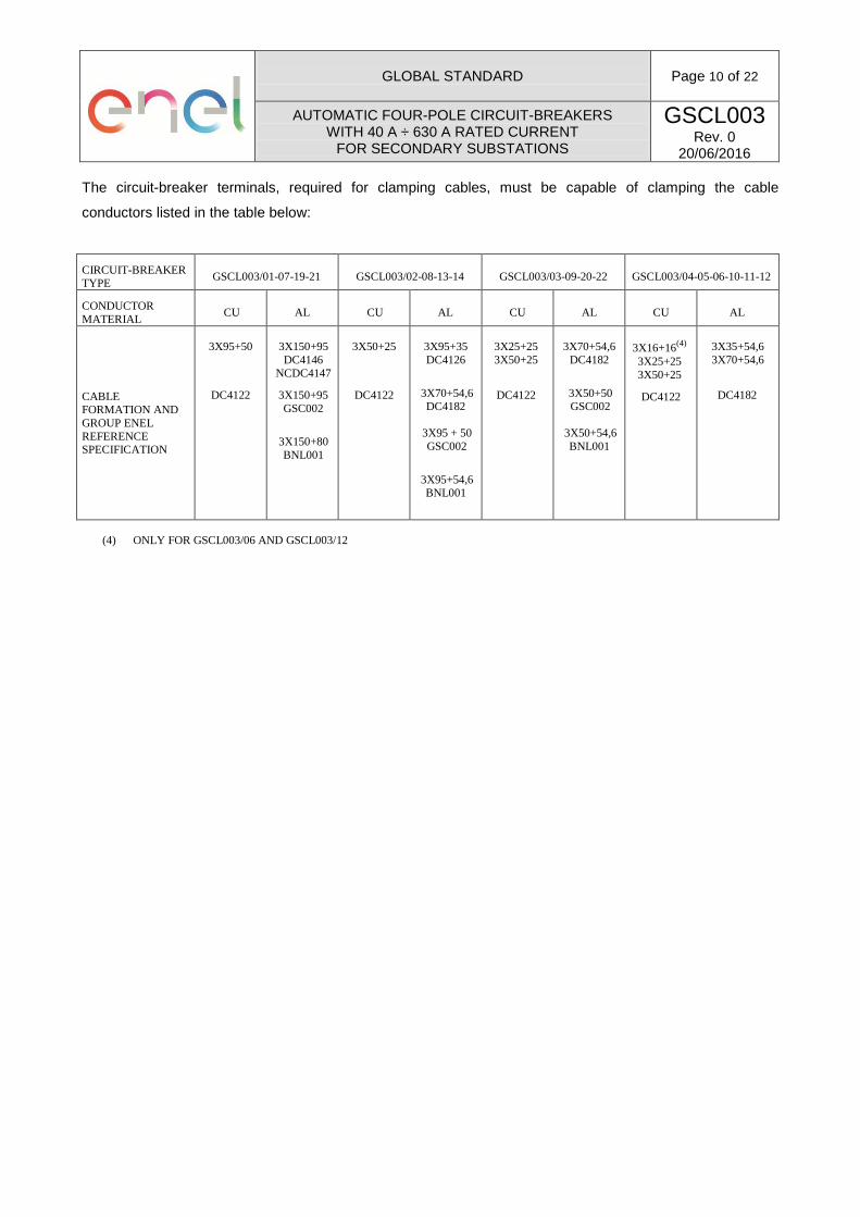
The circuit-breaker terminals, required for clamping cables, must be capable of clamping the cable
conductors listed in the table below:
CIRCUIT-BREAKER TYPE GSCL003/01-07-19-21 GSCL003/02-08-13-14 GSCL003/03-09-20-22 GSCL003/04-05-06-10-11-12
CONDUCTOR MATERIAL CU AL CU AL CU AL CU AL
CABLE FORMATION AND GROUP ENEL REFERENCE SPECIFICATION
3X95+50
DC4122
3X150+95 DC4146
NCDC4147
3X150+95 GSC002
3X150+80 BNL001
3X50+25
DC4122
3X95+35 DC4126
3X70+54,6 DC4182
3X95 + 50 GSC002
3X95+54,6 BNL001
3X25+25 3X50+25
DC4122
3X70+54,6
DC4182
3X50+50 GSC002
3X50+54,6 BNL001
3X16+16(4)
3X25+25 3X50+25
DC4122
3X35+54,6 3X70+54,6
DC4182
(4) ONLY FOR GSCL003/06 AND GSCL003/12

GLOBAL STANDARD
Page 11 of 22
AUTOMATIC FOUR-POLE CIRCUIT-BREAKERS WITH 40 A ÷ 630 A RATED CURRENT
FOR SECONDARY SUBSTATIONS
GSCL003 Rev. 0
20/06/2016
8.2 Characteristics of circuit-breaker with 350 A rated current
CHARACTERISTICS
Circuit-breaker type four-pole, suitable for isolation, moulded case type with organic material enclosure without accessible metallic parts, maintenance free
Installation type vertical IP code (5) IP3X (6) Frequency (Hz) 50 Making operating system independent manual with non-removable lever
Breaking operating system independent manual with non-removable lever and with thermal and magnetic releases
Rated voltage (Ue) (V) 400 Rated insulation voltage (Ui) (V) 690 Rated impulse withstand voltage (Uimp) (kV) 8 Rated uninterrupted current at 40 °C (Iu) (A) 350 Service uninterrupted Utilization category A Rated service short-circuit breaking capacity (Ics) (kA) 25
Phase thermal release (1 per phase)(7) - conventional free air thermal current at 40 °C (Ith) (A) 280 ÷ 350 - conventional non tripping current (A) 1.05 Ith - conventional tripping current (A) 1.30 Ith - maximum breaking time at 2 Ith on single pole with cool release at ambient temperature of 40 °C (min) 12
Phase magnetic release (1 per phase) - current setting (Im) (A) 1750 - breaking time for a tripping current of 3 Im (ms) ≤ 15 - tripping current precision (%) ± 20
Neutral thermal release (7) - conventional free air thermal current at 40 °C (Ith) (A) 140 ÷ 175 - conventional non tripping current (A) 1.05 Ith - conventional tripping current (A) 1.30 Ith - maximum breaking time at 2 Ith on single pole with cool release at ambient temperature of 40 °C (min) 12
Neutral magnetic release - current setting (Im) (A) 1000 - breaking time for a tripping current of 3 Im (ms) ≤ 15 - tripping current precision (%) ± 20
Ambient temperature - upper limit (°C) 40 - lower limit (°C) -20
Temperature-rise limit of terminals (at Ith = 350 A) (K) 60
Nominal tightening torque of terminals (Nm) 20 (5) EXCEPT FOR THE BACK SIDE OF THE DEVICE (6) EXCEPT FOR THE TERMINAL COVERINGS (LOAD CABLE SIDE) FOR WHICH THE IP2X DEGREE OF PROTECTION IS
REQUIRED (7) ADJUSTABLE FROM 0.8 TO 1 ITH (FACTORY DEFAULT VALUE SET AT 1 ITH).
GLOBAL STANDARD
Page 12 of 22
AUTOMATIC FOUR-POLE CIRCUIT-BREAKERS WITH 40 A ÷ 630 A RATED CURRENT
FOR SECONDARY SUBSTATIONS
GSCL003 Rev. 0
20/06/2016
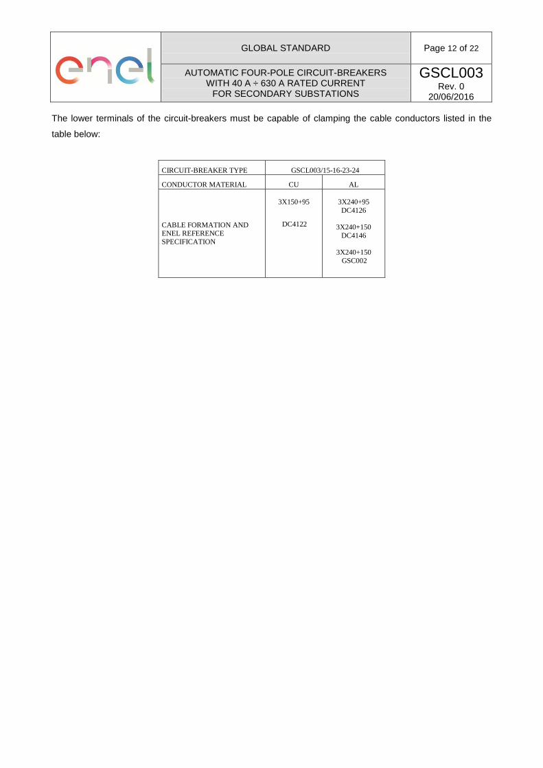
The lower terminals of the circuit-breakers must be capable of clamping the cable conductors listed in the
table below:
CIRCUIT-BREAKER TYPE GSCL003/15-16-23-24
CONDUCTOR MATERIAL CU AL
CABLE FORMATION AND ENEL REFERENCE SPECIFICATION
3X150+95
DC4122
3X240+95 DC4126
3X240+150
DC4146
3X240+150 GSC002
GLOBAL STANDARD
Page 13 of 22
AUTOMATIC FOUR-POLE CIRCUIT-BREAKERS WITH 40 A ÷ 630 A RATED CURRENT
FOR SECONDARY SUBSTATIONS
GSCL003 Rev. 0
20/06/2016
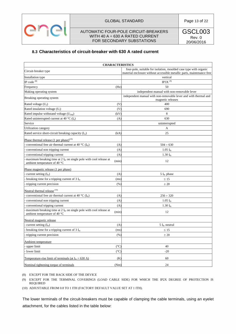
8.3 Characteristics of circuit-breaker with 630 A rated current
CHARACTERISTICS
Circuit-breaker type four-pole, suitable for isolation, moulded case type with organic material enclosure without accessible metallic parts, maintenance free
Installation type vertical IP code (8) IP3X (9) Frequency (Hz) 50 Making operating system independent manual with non-removable lever
Breaking operating system independent manual with non-removable lever and with thermal and magnetic releases
Rated voltage (Ue) (V) 400 Rated insulation voltage (Ui) (V) 690 Rated impulse withstand voltage (Uimp) (kV) 8 Rated uninterrupted current at 40 °C (Iu) (A) 630 Service uninterrupted Utilization category A Rated service short-circuit breaking capacity (Ics) (kA) 25
Phase thermal release (1 per phase)(10) - conventional free air thermal current at 40 °C (Ith) (A) 504 ÷ 630 - conventional non tripping current (A) 1.05 Ith - conventional tripping current (A) 1.30 Ith - maximum breaking time at 2 Ith on single pole with cool release at ambient temperature of 40 °C (min) 12
Phase magnetic release (1 per phase) - current setting (Im) (A) 5 Ith phase - breaking time for a tripping current of 3 Im (ms) ≤ 15 - tripping current precision (%) ± 20
Neutral thermal release (10) - conventional free air thermal current at 40 °C (Ith) (A) 256 ÷ 320 - conventional non tripping current (A) 1.05 Ith - conventional tripping current (A) 1.30 Ith - maximum breaking time at 2 Ith on single pole with cool release at ambient temperature of 40 °C (min) 12
Neutral magnetic release - current setting (Im) (A) 5 Ith neutral - breaking time for a tripping current of 3 Im (ms) ≤ 15 - tripping current precision (%) ± 20
Ambient temperature - upper limit (°C) 40 - lower limit (°C) -20
Temperature-rise limit of terminals (at Ith = 630 A) (K) 60
Nominal tightening torque of terminals (Nm) 24 (8) EXCEPT FOR THE BACK SIDE OF THE DEVICE (9) EXCEPT FOR THE TERMINAL COVERINGS (LOAD CABLE SIDE) FOR WHICH THE IP2X DEGREE OF PROTECTION IS
REQUIRED (10) ADJUSTABLE FROM 0.8 TO 1 ITH (FACTORY DEFAULT VALUE SET AT 1 ITH).
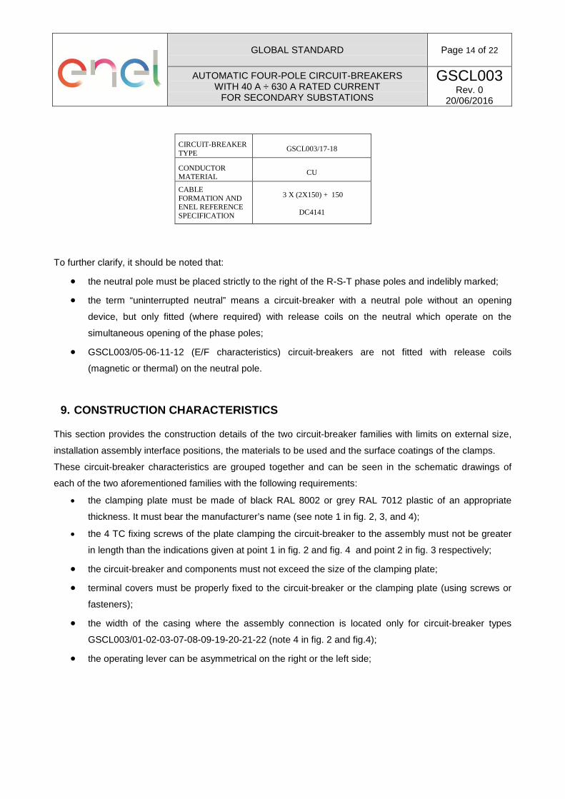
The lower terminals of the circuit-breakers must be capable of clamping the cable terminals, using an eyelet
attachment, for the cables listed in the table below:
GLOBAL STANDARD
Page 14 of 22
AUTOMATIC FOUR-POLE CIRCUIT-BREAKERS WITH 40 A ÷ 630 A RATED CURRENT
FOR SECONDARY SUBSTATIONS
GSCL003 Rev. 0
20/06/2016
CIRCUIT-BREAKER TYPE GSCL003/17-18
CONDUCTOR MATERIAL CU
CABLE FORMATION AND ENEL REFERENCE SPECIFICATION
3 X (2X150) + 150
DC4141
To further clarify, it should be noted that:
• the neutral pole must be placed strictly to the right of the R-S-T phase poles and indelibly marked;
• the term “uninterrupted neutral” means a circuit-breaker with a neutral pole without an opening
device, but only fitted (where required) with release coils on the neutral which operate on the
simultaneous opening of the phase poles;
• GSCL003/05-06-11-12 (E/F characteristics) circuit-breakers are not fitted with release coils
(magnetic or thermal) on the neutral pole.
9. CONSTRUCTION CHARACTERISTICS
This section provides the construction details of the two circuit-breaker families with limits on external size,
installation assembly interface positions, the materials to be used and the surface coatings of the clamps.
These circuit-breaker characteristics are grouped together and can be seen in the schematic drawings of
each of the two aforementioned families with the following requirements:
• the clamping plate must be made of black RAL 8002 or grey RAL 7012 plastic of an appropriate
thickness. It must bear the manufacturer’s name (see note 1 in fig. 2, 3, and 4);
• the 4 TC fixing screws of the plate clamping the circuit-breaker to the assembly must not be greater
in length than the indications given at point 1 in fig. 2 and fig. 4 and point 2 in fig. 3 respectively;
• the circuit-breaker and components must not exceed the size of the clamping plate;
• terminal covers must be properly fixed to the circuit-breaker or the clamping plate (using screws or
fasteners);
• the width of the casing where the assembly connection is located only for circuit-breaker types
GSCL003/01-02-03-07-08-09-19-20-21-22 (note 4 in fig. 2 and fig.4);
• the operating lever can be asymmetrical on the right or the left side;

GLOBAL STANDARD
Page 15 of 22
AUTOMATIC FOUR-POLE CIRCUIT-BREAKERS WITH 40 A ÷ 630 A RATED CURRENT
FOR SECONDARY SUBSTATIONS
GSCL003 Rev. 0
20/06/2016
• the position of the 4 openings (optionally one single opening) of the plate is free, but it must allow the
connection of the assembly with the circuit-breaker mounted on its clamping plate (only for circuit-
breaker types GSCL003/01-02-03-07-08-09-19-20-21-22 (note 7 in fig. 2 and fig.4);
• the clamping screws of the circuit-breaker to the clamping plate must not stick out of rear side of the
plate itself;
• the line and load clamp-screws of the circuit-breaker must operate with the insulated spanners in the
EA0210 specification for types 3101;
• the line and load clamp-screws of the circuit-breaker must operate with the insulated spanners in the
EA0211 specification for types 3102;
• the line and load clamp-screws of the circuit-breaker must operate with the insulated spanners in the
EA0037 specification for types 3103;
• the circuit-breakers must be fitted with insulating separators between each terminal fixed on the
enclosure of the device in order to guarantee electric insulation between terminals even if their
coverings have been removed (note 10 in fig. 2 and fig. 4);
• the bolts made of iron must be protected using electrolytic zinc plating (minimum thickness 12µm);
• each circuit-breaker must have a Barcode to allow it to be traced in the field (see Operational Note
PVR 006); it must be placed on the body of the circuit-breaker so that it is still visible when flanked
by other circuit-breakers.
• Marking, technical documentation and packaging shall be in the language of the destination country for the circuit-breakers.

GLOBAL STANDARD
Page 16 of 22
AUTOMATIC FOUR-POLE CIRCUIT-BREAKERS WITH 40 A ÷ 630 A RATED CURRENT
FOR SECONDARY SUBSTATIONS
GSCL003 Rev. 0
20/06/2016

GLOBAL STANDARD
Page 17 of 22
AUTOMATIC FOUR-POLE CIRCUIT-BREAKERS WITH 40 A ÷ 630 A RATED CURRENT
FOR SECONDARY SUBSTATIONS
GSCL003 Rev. 0
20/06/2016
Italian English
TERMINALI TERMINALS
COPRITERMINALI TERMINAL COVERS
PIASTRA FISSAGGIO INTERRUTTORE (nota 1) CIRCUIT-BREAKER CLAMPING PLATE (note 1)
n. 4 viti TC M5 x (S1+5) UNI 6107-67 DIN84 n. 4 rosette elastiche in acciaio 5,3x11 DIN 137
No. 4 screws TC M5 x (S1+5) UNI 6107-67 DIN84 No. 4 steel spring washers 5.3x11 DIN 137
n. 4 viti TC M8 x (S2+15) UNI 6107-67 DIN84 n. 4 rosette elastiche in acciaio 8,4x15 DIN 137
No. 4 screws TC M8 x (S2+15) UNI 6107-67 DIN84 No. 4 steel spring washers 8.4x15 DIN 137
Le viti di connessione dei morsetti devono essere del tipo ad esagono incassato per chiavi con apertura S = 5 mm per fase e neutro; utilizzo di chiave ENEL EA0210 con coppia di serraggio prev.
Connection clamp screws must be embedded hexagon type for S = 5 mm Allen spanners for phase or neutral; use ENEL EA0210 spanner with the required torque
Vite M8 (max) EN ISO 4762 Ed. marzo 2004 con cava esag. Apertura S = 5 mm per fase e neutro; Utilizzo di chiave EA0210 con coppia serraggio prevista a seconda della taglia di interruttore.
EN ISO 4762 Ed. March 2004 M8 (max) screws with embedded hexagon type for S = 5 mm for phase or neutral; Use EA0210 spanner with the required torque for the size of the circuit-breaker.
Il morsetto del neutro deve essere idoneo al serraggio del conduttore relativo sia al cavo in rame di tabella DC 4122 che al cavo in alluminio di tabella DC 4126 – DC4146 e DC4182
The neutral clamp must be able to tighten the conductor of the copper cable in specifications DC4126, DC4146 and DC4182
La bulloneria di fissaggio e tutti gli accessori in materiale ferroso devono essere protetti con zincatura elettrolitica FeZn 8c UNI ISO 2081 e UNI ISO 4095
The clamping bolts and all iron accessories must be protected using electrolytic zinc plating FeZn 8c UNI ISO 2081 and UNI ISO 4095
Le viti 3-4 devono essere collaudate secondo UNI ISO 3269.
The 3-4 screws must be inspected according to UNI ISO 3269.
*) Spazio destinato alla motorizzazione *) Space allocated to motor

GLOBAL STANDARD
Page 18 of 22
AUTOMATIC FOUR-POLE CIRCUIT-BREAKERS WITH 40 A ÷ 630 A RATED CURRENT
FOR SECONDARY SUBSTATIONS
GSCL003 Rev. 0
20/06/2016
GLOBAL STANDARD
Page 19 of 22
AUTOMATIC FOUR-POLE CIRCUIT-BREAKERS WITH 40 A ÷ 630 A RATED CURRENT
FOR SECONDARY SUBSTATIONS
GSCL003 Rev. 0
20/06/2016
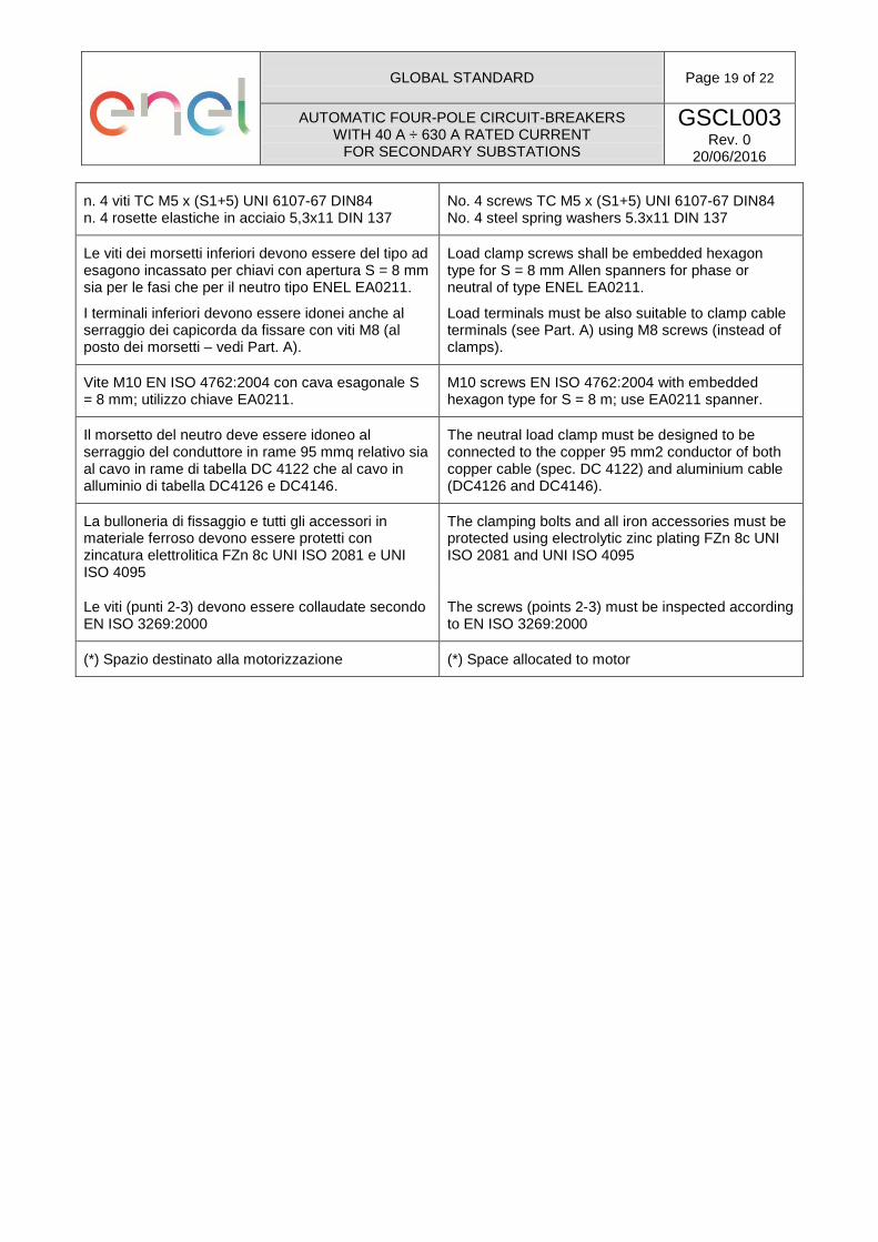
n. 4 viti TC M5 x (S1+5) UNI 6107-67 DIN84 n. 4 rosette elastiche in acciaio 5,3x11 DIN 137
No. 4 screws TC M5 x (S1+5) UNI 6107-67 DIN84 No. 4 steel spring washers 5.3x11 DIN 137
Le viti dei morsetti inferiori devono essere del tipo ad esagono incassato per chiavi con apertura S = 8 mm sia per le fasi che per il neutro tipo ENEL EA0211.
I terminali inferiori devono essere idonei anche al serraggio dei capicorda da fissare con viti M8 (al posto dei morsetti – vedi Part. A).
Load clamp screws shall be embedded hexagon type for S = 8 mm Allen spanners for phase or neutral of type ENEL EA0211.
Load terminals must be also suitable to clamp cable terminals (see Part. A) using M8 screws (instead of clamps).
Vite M10 EN ISO 4762:2004 con cava esagonale S = 8 mm; utilizzo chiave EA0211.
M10 screws EN ISO 4762:2004 with embedded hexagon type for S = 8 m; use EA0211 spanner.
Il morsetto del neutro deve essere idoneo al serraggio del conduttore in rame 95 mmq relativo sia al cavo in rame di tabella DC 4122 che al cavo in alluminio di tabella DC4126 e DC4146.
The neutral load clamp must be designed to be connected to the copper 95 mm2 conductor of both copper cable (spec. DC 4122) and aluminium cable (DC4126 and DC4146).
La bulloneria di fissaggio e tutti gli accessori in materiale ferroso devono essere protetti con zincatura elettrolitica FZn 8c UNI ISO 2081 e UNI ISO 4095
The clamping bolts and all iron accessories must be protected using electrolytic zinc plating FZn 8c UNI ISO 2081 and UNI ISO 4095
Le viti (punti 2-3) devono essere collaudate secondo EN ISO 3269:2000
The screws (points 2-3) must be inspected according to EN ISO 3269:2000
(*) Spazio destinato alla motorizzazione (*) Space allocated to motor

GLOBAL STANDARD
Page 20 of 22
AUTOMATIC FOUR-POLE CIRCUIT-BREAKERS WITH 40 A ÷ 630 A RATED CURRENT
FOR SECONDARY SUBSTATIONS
GSCL003 Rev. 0
20/06/2016
Italian English
TERMINALI TERMINALS
COPRITERMINALI TERMINAL COVERS
PIASTRA FISSAGGIO INTERRUTTORE (nota 1) CIRCUIT-BREAKER CLAMPING PLATE (note 1)
n° 4 viti M8x25 complete di dadi e rosette (per applicazione su supporto distanziatore)
No. 4 M8x25 screws complete with nuts and washers (for application to separator assembly)
Le viti dei morsetti inferiori devono essere del tipo ad esagono incassato per chiavi con apertura S = 8 mm sia per le fasi che per il neutro tipo ENEL EA0211.
I terminali inferiori devono essere idonei anche al serraggio dei capicorda da fissare con viti M8 (al posto dei morsetti – vedi Part. A).
Load clamp screws shall be embedded hexagon type for S = 8 mm Allen spanners for phase or neutral of type ENEL EA0211.
Load terminals must be also suitable to clamp cable terminals (see Part. A) using M8 screws (instead of clamps).
Viti M10 oppure M12 con rosette piane ed elastiche, da applicare su capocorda di larghezza massima 31 mm con foro Ø13
M10 or M12 screws with spring and flat washers, for application on cable terminals with a maximum width of 31 mm and a Ø13 hole
GLOBAL STANDARD
Page 21 of 22
AUTOMATIC FOUR-POLE CIRCUIT-BREAKERS WITH 40 A ÷ 630 A RATED CURRENT
FOR SECONDARY SUBSTATIONS
GSCL003 Rev. 0
20/06/2016
10. SUPPLY REQUIREMENTS
Each circuit-breaker must have its own individual packaging and all the accessories for its correct use,
installation and start-up. In particular, each package must contain:
- n. 1 circuit-breaker already mounted to the clamping plate with insulating separators between the terminals and the clamp covers already mounted;
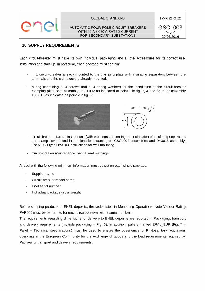
- a bag containing n. 4 screws and n. 4 spring washers for the installation of the circuit-breaker clamping plate onto assembly GSCL002 as indicated at point 1 in fig. 2, 4 and fig. 5; or assembly DY3018 as indicated as point 2 in fig. 3;
- circuit-breaker start-up instructions (with warnings concerning the installation of insulating separators and clamp covers) and instructions for mounting on GSCL002 assemblies and DY3018 assembly; For MCCB type DY3103 instructions for wall mounting.
- Circuit-breaker maintenance manual and warnings.
A label with the following minimum information must be put on each single package:
- Supplier name
- Circuit-breaker model name
- Enel serial number
- Individual package gross weight
.
Before shipping products to ENEL deposits, the tasks listed in Monitoring Operational Note Vendor Rating
PVR006 must be performed for each circuit-breaker with a serial number.
The requirements regarding dimensions for delivery to ENEL deposits are reported in Packaging, transport
and delivery requirements (multiple packaging – Fig. 6). In addition, pallets marked EPAL_EUR (Fig. 7 –
Pallet – Technical specifications) must be used to ensure the observance of Phytosanitary regulations
operating in the European Community for the exchange of goods and the load requirements required by
Packaging, transport and delivery requirements.

GLOBAL STANDARD
Page 22 of 22
AUTOMATIC FOUR-POLE CIRCUIT-BREAKERS WITH 40 A ÷ 630 A RATED CURRENT
FOR SECONDARY SUBSTATIONS
GSCL003 Rev. 0
20/06/2016
Figure 6: Multiple packaging
Figure 7: Pallet – Technical specifications
≤ 1.200 mm
≤ 1.000 mm
≤ 800 mm
Max weight: 620 kg