Assessment of Unsymmetrical Voltage Sag Effectson … · Assessment of Unsymmetrical Voltage Sag...
20
FACTA UNIVERSITATIS (NI ˇ S) SER.: ELEC.ENERG. vol. 22, no. 1, December 2009, 341-360 Assessment of Unsymmetrical Voltage Sag Effectson AC Adjustable Speed Drives Milutin Petronijevi´ c, Nebojˇ sa Mitrovi´ c, Vojkan Kosti´ c, and Borislav Jefteni´ c Abstract: This paper analyses the influence of unsymmetrical voltage sags on the in- crease of torque and speed deviation induction motor adjustable speed drives. The three following general types of induction motor drives control are analysed: scalar- controlled (V/Hz), rotor-field-oriented (RFO) and direct-torque-controlled (DTC). The analytical expression for variations of dc link voltage incorporated into the corre- sponding drive models and formulas for assessment of current/torque deviation are derived depending on the applied control algorithm. Afterwards, the presented the- oretical results for the deterioration of motor drive performance due to voltage sags are validated experimentally. Measurements of sag-caused mechanical vibrations are used for the additional verification of the obtained results. Keywords: Power quality, voltage sag, induction motor drives, speed and torque deviation. 1 Introduction V OLTAGE sags (dips) are power quality problems with the most often appear- ances in public power supply network. Sensitivity of adjustable speed drives (ASDs) to voltage sags was a subject of numerous studies and experimental re- searches (e.g. [1]). In continuous process applications, stop electric drives may occur due to deviations in the speed and/or electromagnetic torque. Majority of the previous works was, concentrated only on determining sensitivity limits related Manuscript received on June 22, 2009. M. Petronijevi´ c, N. Mitrovi´ c, and V. Kosti´ c are with Faculty of Electronic Engineering, Uni- versity of Niˇ s, A. Medvedeva 14, 18 000 Niˇ s, Serbia (e-mails: [milutin.petronijevic; nebojsa.mitrovic; vojkan.kostic]@elfak.ni.ac.rs). B. Jefteni´ c is with Faculty of Electrical Engineering, University of Belgrade, K. Alaksandra 73, 11 000 Belgrade, Serbia (e- mail: [email protected]). 341
-
Upload
nguyenkiet -
Category
Documents
-
view
233 -
download
0
Transcript of Assessment of Unsymmetrical Voltage Sag Effectson … · Assessment of Unsymmetrical Voltage Sag...
FACTA UNIVERSITATIS (NIS)
SER.: ELEC. ENERG. vol. 22, no. 1, December 2009, 341-360
Assessment of Unsymmetrical Voltage Sag Effectson ACAdjustable Speed Drives
Milutin Petronijevi c, Nebojsa Mitrovi c, Vojkan Kostic,and Borislav Jeftenic
Abstract: This paper analyses the influence of unsymmetrical voltage sags on the in-crease of torque and speed deviation induction motor adjustable speed drives. Thethree following general types of induction motor drives control are analysed: scalar-controlled (V/Hz), rotor-field-oriented (RFO) and direct-torque-controlled(DTC). Theanalytical expression for variations of dc link voltage incorporated into the corre-sponding drive models and formulas for assessment of current/torque deviation arederived depending on the applied control algorithm. Afterwards, the presented the-oretical results for the deterioration of motor drive performance due to voltage sagsare validated experimentally. Measurements of sag-causedmechanical vibrations areused for the additional verification of the obtained results.
Keywords: Power quality, voltage sag, induction motor drives, speed and torquedeviation.
1 Introduction
VOLTAGE sags (dips) are power quality problems with the most often appear-ances in public power supply network. Sensitivity of adjustable speed drives
(ASDs) to voltage sags was a subject of numerous studies and experimental re-searches (e.g. [1]). In continuous process applications, stop electric drives mayoccur due to deviations in the speed and/or electromagnetictorque. Majority ofthe previous works was, concentrated only on determining sensitivity limits related
Manuscript received on June 22, 2009.M. Petronijevic, N. Mitrovic, and V. Kostic are with Faculty of Electronic Engineering, Uni-
versity of Nis, A. Medvedeva 14, 18 000 Nis, Serbia (e-mails: [milutin.petronijevic;nebojsa.mitrovic; vojkan.kostic]@elfak.ni.ac.rs). B. Jeftenic is with Facultyof Electrical Engineering, University of Belgrade, K. Alaksandra 73, 11 000 Belgrade, Serbia (e-mail: [email protected]).
341
342 M. Petronijevic, N. Mitrovic, V. Kostic, and B. Jefteni´c:
to disconnection/tripping of analysed or tested ASDs due tothe activation of theirovercurrent/undervoltage protection systems.
The paper researches behaviour of scalar controlled (V/Hz), rotor field oriented(RFO) and direct torque controlled (DTC) induction motor (IM) drives in speedand torque controlled application in voltage sags circumstances. Analytical results,presented in this paper, show differences in behaviour of electrical drives, depend-ing on the applied control algorithm, and suggest opportunities for improvement inpractical applications.
The recent researches in ASD sag sensitivity did not take into account typeand actual settings of applied drive control, and this paperaims to fill this gap bypresenting corresponding analytical relations and experimental results for dc linkvoltage ripple, torque ripple and mechanical vibrations caused by unbalanced volt-age sags. The use of experimental measurements was particularly important for theverification of the developed models and control algorithmsof high-performanceASDs, as these are very complex. The presented results show that classical DTCdrives using torque and flux comparators practically insensible to an increase of dcvoltage ripple, while RFO-controlled drives and DTC driveswith PI regulators forflux and torque control are only slightly sensible.
Section II of this paper provides a short description of single-line-to-groundfaults caused voltage sags and analytically describes their consequences on dc linkvoltage deviation. Section III presents three analysed general control methods:scalar control (V/Hz), direct torque control (DTC) and rotor flux oriented (RFO)control. Section IV analytically compares influence of unbalanced voltage sags onASD performance, and points out main differences in responses of ASDs with dif-ferent controls. Based on the analysis of obtained analytical results, in this sectionalso discusses and highlights key parameters and characteristics of ASDs affectedby voltage sags. Finally, the last section of the paper presents some experimentalresults, including vibration spectra, for sag-caused torque harmonics.
2 Voltage sags effects
Unbalanced voltage sags are of particular importance during the assessment ofequipment sensitivity, as they are usually caused by single-line-to-ground faults(SLGFs), which are the most frequent types of system fault (responsible for around70% of all faults, [2]). As one or two-phase voltages of SLGF-caused unbalancedsingle-phase and two-phase voltage sags are either unaffected, or with only a minorreduction in magnitude. During sag, ASD dc link voltage may,depending on themagnitude and duration of the experienced unbalanced sags,remain above the un-dervoltage protection limit. Numerous measurements around the world ( [3]) point
Assessment of unsymmetrical voltage sag .. 343
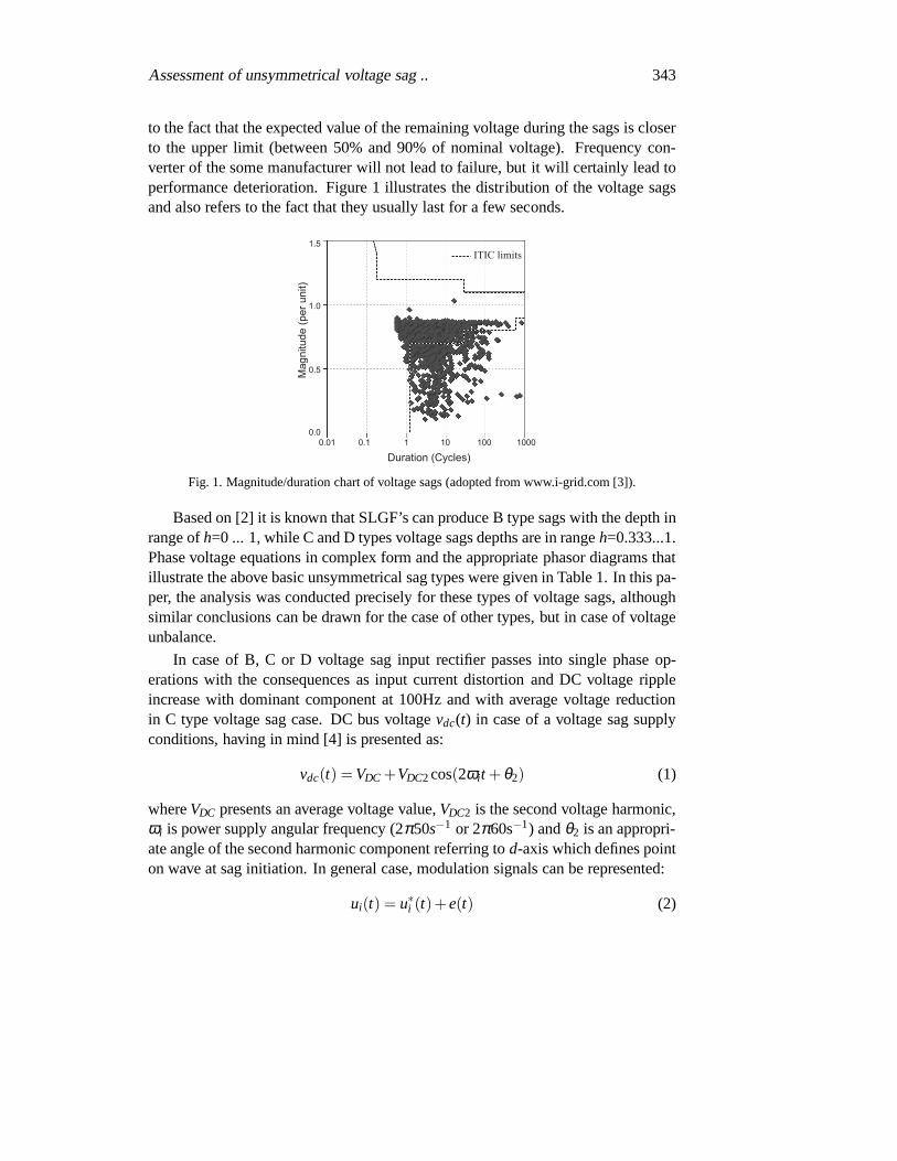
to the fact that the expected value of the remaining voltage during the sags is closerto the upper limit (between 50% and 90% of nominal voltage). Frequency con-verter of the some manufacturer will not lead to failure, butit will certainly lead toperformance deterioration. Figure 1 illustrates the distribution of the voltage sagsand also refers to the fact that they usually last for a few seconds.
Fig. 1. Magnitude/duration chart of voltage sags (adopted from www.i-grid.com [3]).
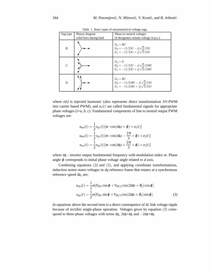
Based on [2] it is known that SLGF’s can produce B type sags with the depth inrange ofh=0 ... 1, while C and D types voltage sags depths are in rangeh=0.333...1.Phase voltage equations in complex form and the appropriatephasor diagrams thatillustrate the above basic unsymmetrical sag types were given in Table 1. In this pa-per, the analysis was conducted precisely for these types ofvoltage sags, althoughsimilar conclusions can be drawn for the case of other types,but in case of voltageunbalance.
In case of B, C or D voltage sag input rectifier passes into single phase op-erations with the consequences as input current distortionand DC voltage rippleincrease with dominant component at 100Hz and with average voltage reductionin C type voltage sag case. DC bus voltagevdc(t) in case of a voltage sag supplyconditions, having in mind [4] is presented as:
vdc(t) = VDC +VDC2cos(2ωit + θ2) (1)
whereVDC presents an average voltage value,VDC2 is the second voltage harmonic,ωi is power supply angular frequency (2π50s−1 or 2π60s−1) andθ2 is an appropri-ate angle of the second harmonic component referring tod-axis which defines pointon wave at sag initiation. In general case, modulation signals can be represented:
ui(t) = u∗i (t)+e(t) (2)
344 M. Petronijevic, N. Mitrovic, V. Kostic, and B. Jefteni´c:
Table 1. Basic types of unsymmetrical voltage sags.
Sag type Phasor diagramsolid lines during fault
Phase-to-neutral voltages(h designates remain voltage in p.u.)
BUa = hUUb = −(1/2)U − j(
√3/2)U
Uc = −(1/2)U + j(√
3/2)U
CUa = UUb = −(1/2)U − j(
√3/2)hU
Uc = −(1/2)U + j(√
3/2)hU
DUa = hUUb = −(1/2)hU − j(
√3/2)U
Uc = −(1/2)hU + j(√
3/2)U
wheree(t) is injected harmonic (also represents direct transformation SV-PWMinto carrier based PWM), andui(t) are called fundamental signals for appropriatephase voltages (i=a, b, c). Fundamental components of line to neutral output PWMvoltages are:
uan(t) =12
vdc(t)[m·cos(ωst + ϕ)+ei(t)]
ubn(t) =12
vdc(t)[m·cos(ωst −2π3
+ ϕ)+ei(t)]
ucn(t) =12
vdc(t)[m·cos(ωst +2π3
+ ϕ)+ei(t)]
whereωs - inverter output fundamental frequency with modulation indexm. Phaseangleϕ corresponds to initial phase voltage angle related tod axis.
Combining equations(2) and (3), and applying coordinate transformations,induction motor stator voltages indq reference frame that rotates at a synchronousreference speedωs, are:
uds(t) =12
m[VDC cosϕ +VDC2 cos(2ωit + θ2)cosϕ ]
uqs(t) =12
m[VDC sinϕ +VDC2cos(2ωit + θ2)sinϕ ]. (3)
In equations above the second term is a direct consequence ofdc link voltage ripplebecause of rectifier single-phase operation. Voltages given by equation(3) corre-spond to three-phase voltages with termsωs, 2ωi+ωs and−2ωi+ωs.
Assessment of unsymmetrical voltage sag .. 345
3 Description of Implemented ASD Models
Modern ASDs usually allow end-users to apply different types of control, as mostmanufacturers provide options for selecting different control methods in the sameASD. General classification divides induction motor controls into scalar-based andvector-based ( [5]). The most commonly used control method in industry is a sim-ple scalar-control, also known as constant Voltage/Frequency (V/Hz) control. Al-though very simple, V/Hz control is usually not implementedin high performancedrive applications due to its drawbacks.
Opposite to scalar control, which allows for control of onlyoutput voltage mag-nitude and frequency, vector-based control methods enablecontrol of instantaneousvoltage, current and flux vectors. Accordingly, vector-based control algorithmsresult in significantly improved regulation of drive’s dynamic characteristics andbetter sag ride-through capabilities. This is discussed inmore detail in the nextsubsections.
3.1 V/Hz Controlled ASDs
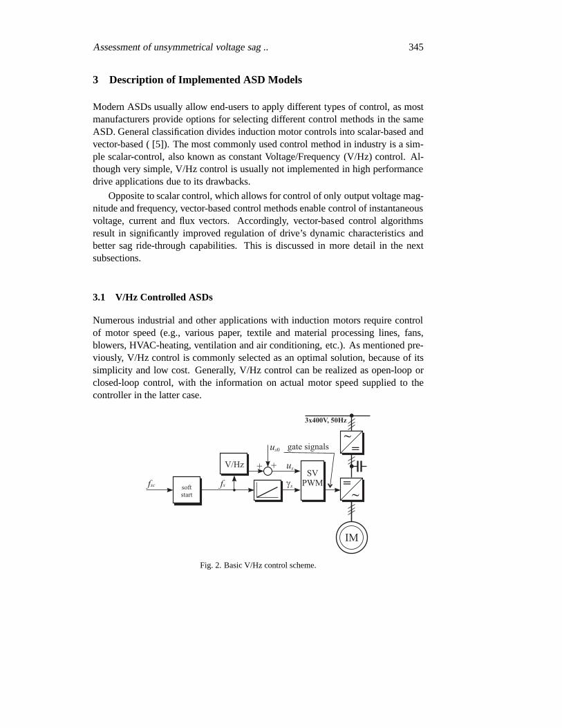
Numerous industrial and other applications with inductionmotors require controlof motor speed (e.g., various paper, textile and material processing lines, fans,blowers, HVAC-heating, ventilation and air conditioning,etc.). As mentioned pre-viously, V/Hz control is commonly selected as an optimal solution, because of itssimplicity and low cost. Generally, V/Hz control can be realized as open-loop orclosed-loop control, with the information on actual motor speed supplied to thecontroller in the latter case.
Fig. 2. Basic V/Hz control scheme.
346 M. Petronijevic, N. Mitrovic, V. Kostic, and B. Jefteni´c:
The V/Hz control can be modified to offset the voltage drop across the inverterand stator resistance, which usually has a significant impact at low output frequen-cies/speeds. Algorithms implemented in practice may also include a dead-timecompensation circuit and a torque estimator based on the measurement of statorcurrents and voltages, instead of using torque sensor. Figure 2 illustrates V/Hzopen-loop control structure, where pulse-width modulation (PWM) is realised ap-plying space vector technique (SVPWM) and output voltage fundamental compo-nent amplitude controlled according to:
u∗s = us0 +Usn
fsnf ∗s (4)
whereUsn and fsn are nominal voltage magnitude and frequency,us0 – voltageoffset (voltage drop compensation) andf ∗s designates output frequency referencevalue.
3.2 Rotor Field Oriented Control of ASDs
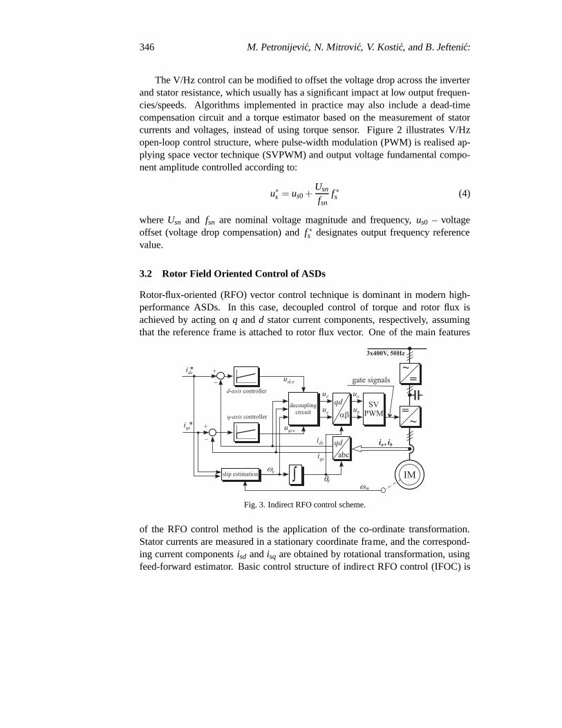
Rotor-flux-oriented (RFO) vector control technique is dominant in modern high-performance ASDs. In this case, decoupled control of torqueand rotor flux isachieved by acting onq andd stator current components, respectively, assumingthat the reference frame is attached to rotor flux vector. Oneof the main features
Fig. 3. Indirect RFO control scheme.
of the RFO control method is the application of the co-ordinate transformation.Stator currents are measured in a stationary coordinate frame, and the correspond-ing current componentsisd andisq are obtained by rotational transformation, usingfeed-forward estimator. Basic control structure of indirect RFO control (IFOC) is
Assessment of unsymmetrical voltage sag .. 347
illustrated in Fig. 3. Two inner PI controlled current loopsfor d andq stator cur-rent components are shown, as well as synchronous speed estimator (ωs, based onreference stator currents components).
3.3 Direct Torque Control of ASDs
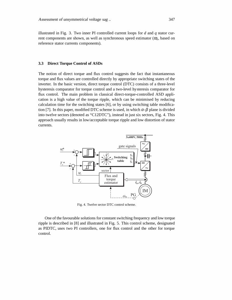
The notion of direct torque and flux control suggests the factthat instantaneoustorque and flux values are controlled directly by appropriate switching states of theinverter. In the basic version, direct torque control (DTC)consists of a three-levelhysteresis comparator for torque control and a two-level hysteresis comparator forflux control. The main problem in classical direct-torque-controlled ASD appli-cation is a high value of the torque ripple, which can be minimised by reducingcalculation time for the switching states [6], or by using switching table modifica-tion [7]. In this paper, modified DTC scheme is used, in whichα-β plane is dividedinto twelve sectors (denoted as “C12DTC”), instead in just six sectors, Fig. 4. Thisapproach usually results in low/acceptable torque ripple and low distortion of statorcurrents.
Fig. 4. Twelve sector DTC control scheme.
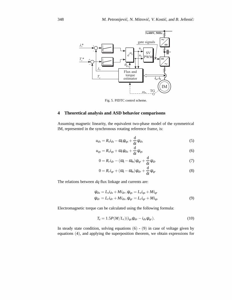
One of the favourable solutions for constant switching frequency and low torqueripple is described in [8] and illustrated in Fig. 5. This control scheme, designatedas PIDTC, uses two PI controllers, one for flux control and theother for torquecontrol.
348 M. Petronijevic, N. Mitrovic, V. Kostic, and B. Jefteni´c:
Fig. 5. PIDTC control scheme.
4 Theoretical analysis and ASD behavior comparisons
Assuming magnetic linearity, the equivalent two-phase model of the symmetricalIM, represented in the synchronous rotating reference frame, is:
uds = Rsids−ωsψqs+ddt
ψds (5)
uqs = Rsiqs+ ωsψds+ddt
ψqs (6)
0 = Rr idr − (ωs−ωm)ψqr +ddt
ψdr (7)
0 = Rr iqr +(ωs−ωm)ψdr +ddt
ψqr (8)
The relations betweendqflux linkage and currents are:
ψds = Lsids+Midr,ψqs = Lsiqs+Miqr
ψdr = Lr idr +Mids,ψqr = Lr iqr +Miqs (9)
Electromagnetic torque can be calculated using the following formula:
Te = 1.5P(M/Lr)(iqsψdr − idsψqr). (10)
In steady state condition, solving equations(6) - (9) in case of voltage given byequations(4), and applying the superposition theorem, we obtain expressions for
Assessment of unsymmetrical voltage sag .. 349
thedqstator currents:
ids = ids0 + Ids2cos(2ωit + δds) (11)
iqs = iqs0 + Iqs2cos(2ωit + δqs), (12)
where average stator current components are given by:
ids0 = K0 [g0 cosϕ −b0sinϕ ] , and
iqs0 = K0 [g0 sinϕ +b0cosϕ ] .
Magnitudes of additional oscillatory stator current components are (for simplicityit will be θ2=0):
Ids2 = K1
√
|y1|2 + |y2|2 +2|y1| |y2|cos(2ϕ + 6 y1 + 6 y2) (13)
Iqs2 = K1
√
|y1|2 + |y2|2 +2|y1| |y2|cos(2ϕ + 6 y1 + π − 6 y2) (14)
The values of certain coefficients in the previous equationsare:
K0 =12
mVDC, K1 =14
mVDC2
y0 = g0 + jb0 = [rs+ jωsLls + jωsM‖(rr/s0 + jωsLlr )]−1
y1 = [rs+ jω1Lls + jω1M‖(rr/s1 + jω1Llr )]−1
y2 = [rs+ jω2Lls + jω2M‖(rr/s2 + jω2Llr )]−1
ω1 = 2ωi + ωs, ω2 = −2ωi + ωs,
s0 =ωs−ω
ωs, s1 =
ω1−ωω1
, s2 =ω2−ω
ω2,
whereω denotes motor rotor angular speed,δds andδqs represents second harmonicstator current components angle respect tod andq axis, respectively.
After combining(12) and(13), taking into account expressions(11), the torquevalue can be calculated in the closed form:
Te = Te0 +Te2cos(2ωit + φ2)+Te4cos(4ωit + φ4), (15)
whereTe0 represents average torque value,Te2 represents the second harmonic com-ponent andTe4 represents the fourth harmonic components.
In the following chapters will be given the discussions on the impact of in-dividual torque and current components, depending on the applied type of ASDscontrol.
350 M. Petronijevic, N. Mitrovic, V. Kostic, and B. Jefteni´c:
4.1 DC link voltage reduction effects
Limitations, as a consequence of the maximum output current(Imax) and maximumoutput voltage (Umax) of an AC/DC converter, can be presented in the appropriatestator variable through the equations:
i2qs+ i2ds≤ I2max, and (16)
u2qs+u2
ds≤U2max (17)
Maximum output current is determined by maximum continuouscurrent of in-verter semiconductor switches or induction motor rated current, i.e. maximum al-lowable thermal capacity of the converter or induction motor. The maximum statorvoltage depends on the available DC-link voltagevDC and pulsewidth modulation(PWM) strategy ( [9]).
Equation(18), in steady state and voltage limit condition, having in mindtherelationships (6)-(11), can be written as:
Ai2ds+Ci2qs+Bidsiqs≤U2max (18)
where:A = R2s + ω2
sL2s, B = 2RsωsM2/Lr andC = R2
s + ω2s σ2L2
s.
This voltage-limit boundary, given by (19), is an ellipse, which area and angleof major axis depend on voltage and frequency. Equation (17)in the same axissystem explains a circle, so range of drive operation can be found in cross sectionof these two ones.
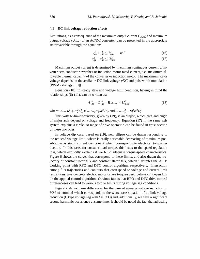
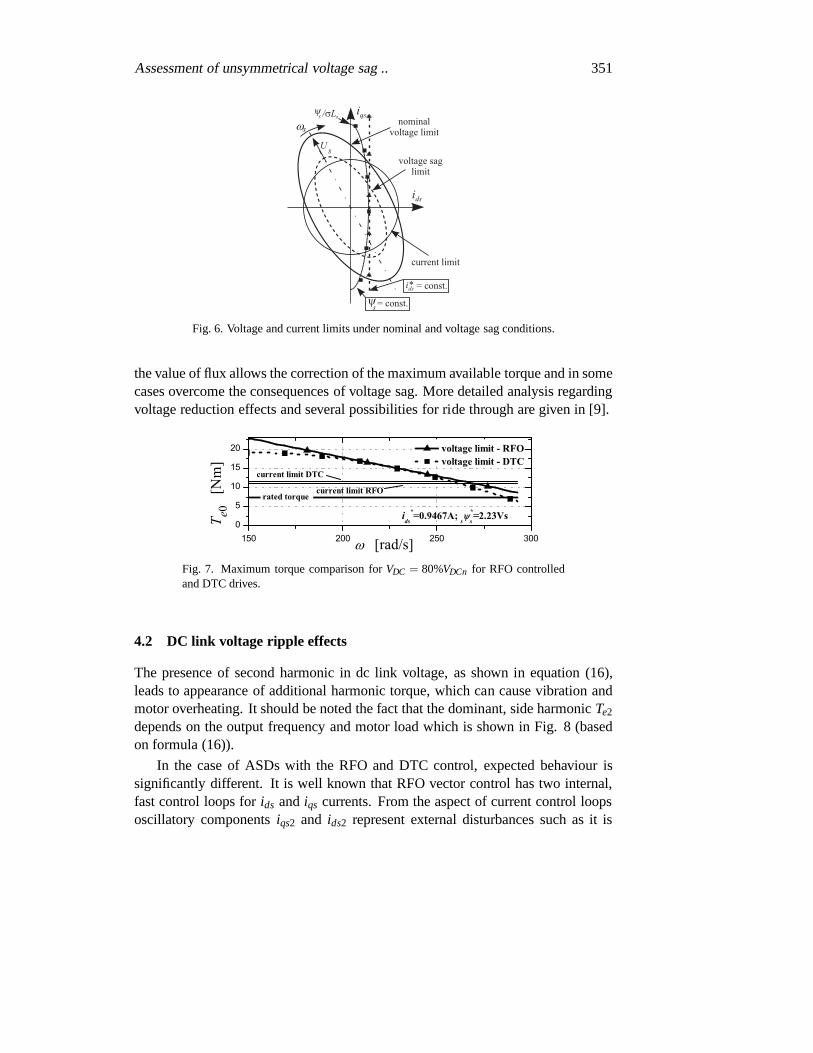
In voltage dip case, based on (19), new ellipse can be drawn responding tothe reduced voltage limit, where is easily noticeable decreasing of maximum pos-sible q-axis stator current component which corresponds to electrical torque re-duction. In this case, for constant load torque, this leads to the speed regulationloss, which explicitly explains if we build adequate torque-speed characteristics.Figure 6 shows the curves that correspond to these limits, and also drawn the tra-jectory of constant rotor flux and constant stator flux, whichillustrates the ASDsworking point with RFO and DTC control algorithm, respectively. Intersectionamong flux trajectories and contours that correspond to voltage and current limitrestrictions give concrete electric motor drives torque/speed behaviour, dependingon the applied control algorithm. Obvious fact is that RFO and DTC drive controldifferenceses can lead to various torque limits during voltage sag conditions.
Figure 7 shows these differences for the case of average voltage reduction to80% of nominal which corresponds to the worst case situationof dc link voltagereduction (C type voltage sag withh=0.333) and, additionally, we have a significantsecond harmonic occurrence at same time. It should be noted the fact that adjusting
Assessment of unsymmetrical voltage sag .. 351
Fig. 6. Voltage and current limits under nominal and voltagesag conditions.
the value of flux allows the correction of the maximum available torque and in somecases overcome the consequences of voltage sag. More detailed analysis regardingvoltage reduction effects and several possibilities for ride through are given in [9].
150 200 250 3000
5
10
15
20 voltage limit - RFO voltage limit - DTC
ids
*=0.9467A; s
*s=2.23Vs
current limit DTC
rated torque current limit RFO
T e0
[Nm
]
[rad/s]Fig. 7. Maximum torque comparison forVDC = 80%VDCn for RFO controlledand DTC drives.
4.2 DC link voltage ripple effects
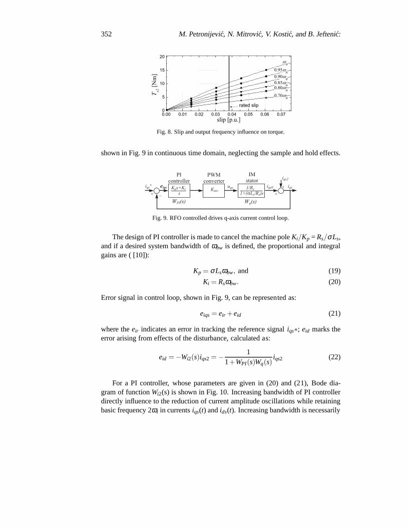
The presence of second harmonic in dc link voltage, as shown in equation (16),leads to appearance of additional harmonic torque, which can cause vibration andmotor overheating. It should be noted the fact that the dominant, side harmonicTe2
depends on the output frequency and motor load which is shownin Fig. 8 (basedon formula (16)).
In the case of ASDs with the RFO and DTC control, expected behaviour issignificantly different. It is well known that RFO vector control has two internal,fast control loops forids andiqs currents. From the aspect of current control loopsoscillatory componentsiqs2 and ids2 represent external disturbances such as it is
352 M. Petronijevic, N. Mitrovic, V. Kostic, and B. Jefteni´c:
0.00 0.01 0.02 0.03 0.04 0.05 0.06 0.070
5
10
15
20
0.70 n
0.80 n
0.85 n
0.90 n
n
T e2 [N
m]
slip [p.u.]
0.95 n
rated slip
Fig. 8. Slip and output frequency influence on torque.
shown in Fig. 9 in continuous time domain, neglecting the sample and hold effects.
Fig. 9. RFO controlled drives q-axis current control loop.
The design of PI controller is made to cancel the machine poleKi/Kp = Rs/σLs,and if a desired system bandwidth ofωbw is defined, the proportional and integralgains are ( [10]):
Kp = σLsωbw, and (19)
Ki = Rsωbw. (20)
Error signal in control loop, shown in Fig. 9, can be represented as:
eiqs = eir +eid (21)
where theeir indicates an error in tracking the reference signaliqs∗; eid marks theerror arising from effects of the disturbance, calculated as:
eid = −Wi2(s)iqs2 = − 11+WPI(s)Wq(s)
iqs2 (22)
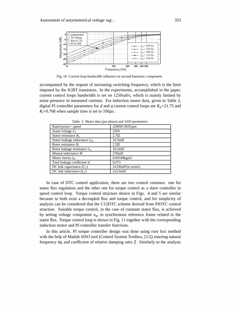
For a PI controller, whose parameters are given in (20) and (21), Bode dia-gram of functionWi2(s) is shown in Fig. 10. Increasing bandwidth of PI controllerdirectly influence to the reduction of current amplitude oscillations while retainingbasic frequency 2ωi in currentsiqs(t) andids(t). Increasing bandwidth is necessarily
Assessment of unsymmetrical voltage sag .. 353
Fig. 10. Current loop bandwidth influence on second harmoniccomponent.
accompanied by the request of increasing switching frequency, which is the limitimposed by the IGBT transistors. In the experiments, accomplished in the paper,current control loops bandwidth is set on 1250rad/s, which is mainly limited bynoise presence in measured currents. For induction motor data, given in Table 2,digital PI controller parameters ford andq current control loops areKp=21.75 andKi=0.768 when sample time is set to 100µs.
Table 2. Motor data (per phase) and ASD parameters.
Rated power / speed 2200W/2835rpmStator voltageUs 230VStator resistanceRs 2.7ΩStator leakage inductanceLls 10.5mHRotor resistanceRr 2.2ΩRotor leakage resistanceLlr 10.5mHMutual inductanceM 270mHMotor inertiaJm 0.00184kgm2Total leakage coefficientσ 0.073DC link capacitance (Cf ) 2x330mF(in series)DC link inductance (L f ) 2x3.6mH
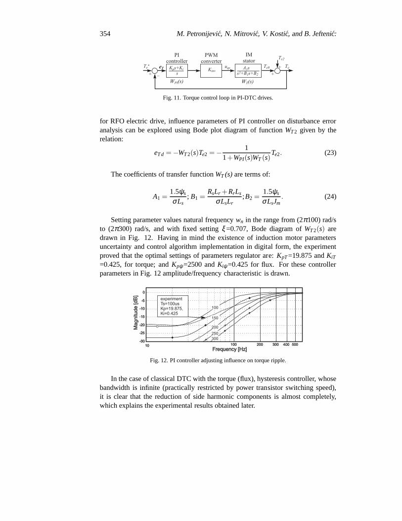
In case of DTC control application, there are two control contours: one forstator flux regulation and the other one for torque control asa slave controller inspeed control loop. Torque control structure shown in Figs.4 and 5 are similarbecause in both exist a decoupled flux and torque control, andfor simplicity ofanalysis can be considered that the C12DTC scheme derived from PIDTC controlstructure. Suitable torque control, in the case of constantstator flux, is achievedby setting voltage componentuqs in synchronous reference frame related to thestator flux. Torque control loop is shown in Fig. 11 together with the correspondinginduction motor and PI controller transfer functions.
In this article, PI torque controller design was done using root loci methodwith the help of Matlab SISO tool (Control System Toolbox, [11]) entering naturalfrequencyωn and coefficient of relative damping ratioξ . Similarly to the analysis
354 M. Petronijevic, N. Mitrovic, V. Kostic, and B. Jefteni´c:
Fig. 11. Torque control loop in PI-DTC drives.
for RFO electric drive, influence parameters of PI controller on disturbance erroranalysis can be explored using Bode plot diagram of functionWT2 given by therelation:
eTd = −WT2(s)Te2 = − 11+WPI(s)WT(s)
Te2. (23)
The coefficients of transfer functionWT (s) are terms of:
A1 =1.5ψs
σLs; B1 =
RsLr +RrLs
σLsLr;B2 =
1.5ψs
σLsJm. (24)
Setting parameter values natural frequencywn in the range from (2π100) rad/sto (2π300) rad/s, and with fixed settingξ =0.707, Bode diagram ofWT2(s) aredrawn in Fig. 12. Having in mind the existence of induction motor parametersuncertainty and control algorithm implementation in digital form, the experimentproved that the optimal settings of parameters regulator are: KpT=19.875 andKiT
=0.425, for torque; andKpψ=2500 andKiψ=0.425 for flux. For these controllerparameters in Fig. 12 amplitude/frequency characteristicis drawn.
Fig. 12. PI controller adjusting influence on torque ripple.
In the case of classical DTC with the torque (flux), hysteresis controller, whosebandwidth is infinite (practically restricted by power transistor switching speed),it is clear that the reduction of side harmonic components isalmost completely,which explains the experimental results obtained later.
Assessment of unsymmetrical voltage sag .. 355
5 Experimental results
The test bed used for testing of ASDs consisted of the following main parts:
1. Rapid prototyping system based on dSpace DS1104 and with modified in-dustrial frequency converter Danfoss VLT5003.
2. Voltage sag generator consisting of three-phase power transformer with in-terchangeable vector group (Dy, Yd or Yy) and with one autotransformer onprimary side and switch network controlled by PLC [12]. Maximum outputpower is 15kVA.
3. Independent real-time data acquisition system (LMG450 Multi Channel PowerAnalyzer) with four current and four voltage inputs and with0.1% basic ac-curacy.
4. Loading induction motor with servo controller interfaced to dSpace DS1104.
5. Vibration measurement instrument VIBROTEST 60 with piezo-electric ac-celeration sensor AS-065 [13].
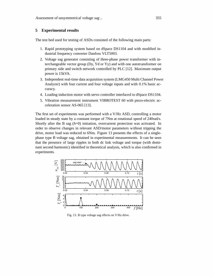
The first set of experiments was performed with a V/Hz ASD, controlling a motorloaded in steady state by a constant torque of 7Nm at rotational speed of 240rad/s.Shortly after the B sag (h=0) initiation, overcurrent protection was activated. Inorder to observe changes in relevant ASD/motor parameters without tripping thedrive, motor load was reduced to 6Nm. Figure 13 presents the effects of a single-phase type B voltage sag, obtained in experimental measurements. It can be seenthat the presence of large ripples in both dc link voltage andtorque (with domi-nant second harmonic) identified in theoretical analysis, which is also confirmed inexperiments.
0.00 0.04 0.08 0.12400450500550600650
t [s]
u DC [V
]
sag start
0.00 0.04 0.08 0.1202468
101214
T e [N
m]
t [s]
0 100 200 300 4000246
k [N
m]
f [Hz]
Fig. 13. B type voltage sag effects on V/Hz drive.
356 M. Petronijevic, N. Mitrovic, V. Kostic, and B. Jefteni´c:
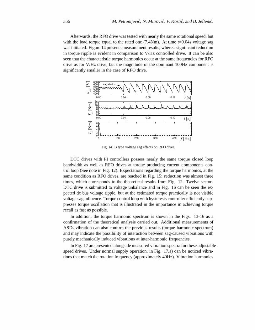
Afterwards, the RFO drive was tested with nearly the same rotational speed, butwith the load torque equal to the rated one (7.4Nm). At timet=0.04s voltage sagwas initiated. Figure 14 presents measurement results, where a significant reductionin torque ripple is evident in comparison to V/Hz controlleddrive. It can be alsoseen that the characteristic torque harmonics occur at the same frequencies for RFOdrive as for V/Hz drive, but the magnitude of the dominant 100Hz component issignificantly smaller in the case of RFO drive.
0.00 0.04 0.08 0.12400450500550600650
t [s]
u D
C [V
]sag start
0.00 0.04 0.08 0.1202468
101214
T e
[Nm
]
t [s]
0 100 200 300 40002468
k [Nm
]
f [Hz]
Fig. 14. B type voltage sag effects on RFO drive.
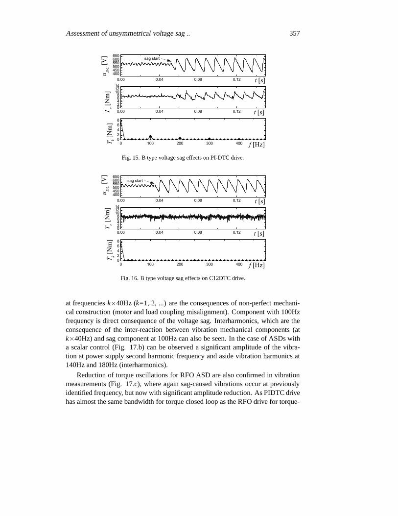
DTC drives with PI controllers possess nearly the same torque closed loopbandwidth as well as RFO drives at torque producing current components con-trol loop (See note in Fig. 12). Expectations regarding the torque harmonics, at thesame condition as RFO drives, are reached in Fig. 15: reduction was almost threetimes, which corresponds to the theoretical results from Fig. 12. Twelve sectorsDTC drive is submitted to voltage unbalance and in Fig. 16 canbe seen the ex-pected dc bus voltage ripple, but at the estimated torque practically is not visiblevoltage sag influence. Torque control loop with hysteresis controller efficiently sup-presses torque oscillation that is illustrated in the importance in achieving torquerecall as fast as possible.
In addition, the torque harmonic spectrum is shown in the Figs. 13-16 as aconfirmation of the theoretical analysis carried out. Additional measurements ofASDs vibration can also confirm the previous results (torqueharmonic spectrum)and may indicate the possibility of interaction between sag-caused vibrations withpurely mechanically induced vibrations at inter-harmonicfrequencies.
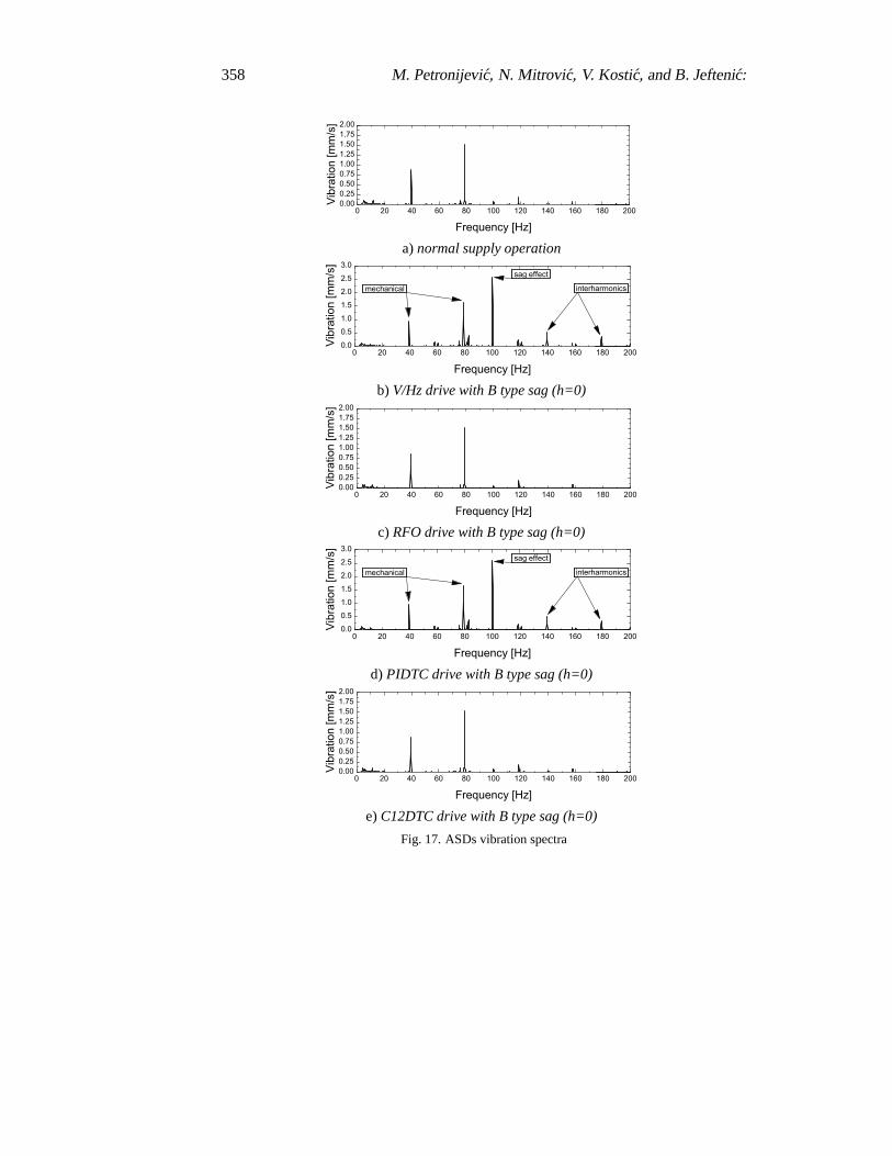
In Fig. 17 are presented alongside measured vibration spectra for these adjustable-speed drives. Under normal supply operation, in Fig. 17.a) can be noticed vibra-tions that match the rotation frequency (approximately 40Hz). Vibration harmonics
Assessment of unsymmetrical voltage sag .. 357
0.00 0.04 0.08 0.12400450500550600650
t [s]
u DC [V
]0.00 0.04 0.08 0.1202468
101214
T e [N
m]
t [s]
0 100 200 300 40002468
k [N
m]
f [Hz]
sag start
Fig. 15. B type voltage sag effects on PI-DTC drive.
0.00 0.04 0.08 0.12400450500550600650
t [s]
u DC [V
]
sag start
0.00 0.04 0.08 0.1202468
101214
T e [N
m]
t [s]
0 100 200 300 40002468
k [Nm
]
f [Hz]
Fig. 16. B type voltage sag effects on C12DTC drive.
at frequenciesk×40Hz (k=1, 2, ...) are the consequences of non-perfect mechani-cal construction (motor and load coupling misalignment). Component with 100Hzfrequency is direct consequence of the voltage sag. Interharmonics, which are theconsequence of the inter-reaction between vibration mechanical components (atk×40Hz) and sag component at 100Hz can also be seen. In the case of ASDs witha scalar control (Fig. 17.b) can be observed a significant amplitude of the vibra-tion at power supply second harmonic frequency and aside vibration harmonics at140Hz and 180Hz (interharmonics).
Reduction of torque oscillations for RFO ASD are also confirmed in vibrationmeasurements (Fig. 17.c), where again sag-caused vibrations occur at previouslyidentified frequency, but now with significant amplitude reduction. As PIDTC drivehas almost the same bandwidth for torque closed loop as the RFO drive for torque-
358 M. Petronijevic, N. Mitrovic, V. Kostic, and B. Jefteni´c:
0 20 40 60 80 100 120 140 160 180 2000.000.250.500.751.001.251.501.752.00
Vibr
atio
n [m
m/s
]
Frequency [Hz]
a)normal supply operation
0 20 40 60 80 100 120 140 160 180 2000.0
0.5
1.0
1.5
2.0
2.5
3.0
Vibr
atio
n [m
m/s
]
Frequency [Hz]
mechanical
sag effect
interharmonics
b) V/Hz drive with B type sag (h=0)
0 20 40 60 80 100 120 140 160 180 2000.000.250.500.751.001.251.501.752.00
Vibr
atio
n [m
m/s
]
Frequency [Hz]
c) RFO drive with B type sag (h=0)
0 20 40 60 80 100 120 140 160 180 2000.0
0.5
1.0
1.5
2.0
2.5
3.0
Vibr
atio
n [m
m/s
]
Frequency [Hz]
mechanical
sag effect
interharmonics
d) PIDTC drive with B type sag (h=0)
0 20 40 60 80 100 120 140 160 180 2000.000.250.500.751.001.251.501.752.00
Vibr
atio
n [m
m/s
]
Frequency [Hz]
e)C12DTC drive with B type sag (h=0)
Fig. 17. ASDs vibration spectra
Assessment of unsymmetrical voltage sag .. 359
producing current components control loop, the corresponding vibration measuringresults are similar (Fig. 17.d). In both cases the reductionof dominant, sag-casusedvibration is almost 4.5 times, while the appearance of additional interharmonicsalmost negligible.
Finally, the measurement of vibration in the case of C12DTC drives confirmedthe analytical results expected in the presence of vibration amplitude and harmonicvalues. In the area of low frequency vibration spectra, in Fig. 17.e) can be seenonly harmonics that are a consequence of the rotation, whilethe vibrations are aresult of voltage sag completely suppressed.
6 Conclusion
Modern adjustable speed drives, regarding to voltage sag condition, have differentcharacteristics, in terms of momentary tripping or partialperformance degradation.This paper, based on analytical expressions, predicts the behaviour of induction mo-tor drives in case of SLGFs caused voltage sags, and then, respecting the differentcontrol algorithms allows assessment torque/speed behaviour of high performancedrives. Based on analytical expression and experimental researches, we concludethat type control algorithm is with great importance considering unsymmetrical sageffects.
High performance drives (with RFO and DTC algorithm) are less sensible onvoltage unbalance, especially drives with traditional DTCtechnique with hystere-sis comparators. Torque or torque-producing current clossed-loop bandwidth is akey parameter with the greatest influence on the amplitude ofunwanted harmonics.Experimental measurements in industrial ASDs in which theyimplemented var-ious control algorithms confirmed the theoretically predicted results. Laboratorymeasurements indicated the potential risk of inter-reaction between vibration me-chanical components and sag-caused torque component, which as a result can beappearance of inter-harmonics whose frequency can be foundin the area of naturalsystem resonance, especially for drives in a wide speed range.
Professional engineers in the field of industrial electric drives can be in thestage of plant system design choose a lower operating speed,which will signifi-cantly reduce possible oscillation in torque. In addition,the application of advancedcontrol methods, particularly traditional DTC technique,is one of the possibilitiesfor overcoming the voltage sag consequences and prevents degradation of ASDsperformance. Further researches will be conducted on the disturbance observerapplication in torque/current control loops aimed to additional torque harmonicssuppression.
360 M. Petronijevic, N. Mitrovic, V. Kostic, and B. Jefteni´c:
References
[1] S. Djokic, K. Stockman, J. Milanovic, J. Desmet, and R.Belmans, “Sensitivity of acadjustable speed drives to voltage sags and short interruptions,” IEEE Trans. PowerDelivery, vol. 20, pp. 494–505, Jan. 2005.
[2] M. H. J. Bollen,Understanding power quality problems: Voltage sags and interrup-tion. New York, USA: IEEE Press series on Pwr. Engineering, 2000.
[3] D. Divan, G. Luckjiff, W. Brumsickle, J. Freeborg, and Bhadkamkar, “I-gridTM: in-frastructure for nationwide real-time power monitoring,”in Industry ApplicationsConference, 2002. 37th IAS Annual Meeting. Conference Record of the, Philadelphia,Pennsylvania, Oct. 2002, pp. 1740–1745.
[4] K. Lee, T. Jahns, W. Berkopec, and T. Lipo, “Closed-form analysis of adjustable-speed drive performance under input-voltage unbalance andsag conditions,”IndustryApplications, IEEE Transactions on, vol. 42, no. 3, pp. 733–741, May-June 2006.
[5] M. P. Kazimierkowski, F. Blaabjerg, and R. Krishnan,Control in Power Electronics– Selected problems. New York, USA: Academic Press, 2002.
[6] N. Nash, “Direct torque control, induction motor vectorcontrol without an encoder,”IEEE Trans. Ind. Appl., vol. 33, no. 2, pp. 333–341, Mar. 1997.
[7] V. Kostic, N. Mitrovic, M. Petronijevic, and B. Jeftenic, “Torque ripple minimiza-tion in direct torque controlled induction motor drive based on duty ratio modulationmethod,”Scientific Bulletin of ”Politehnica”, Trans. on Automatic Control and Com-puter Science, vol. 49(63), no. 1, pp. 87–92, 2004.
[8] Y. Lai and J. Chen, “A new approch to direct torque controlof induction motor drivesfor constant inverter switching frequency and torque ripple reduction,”IEEE Trans.On Energy Conversion, vol. 16, no. 3, pp. 220–227, Sept. 2001.
[9] M. Petronijevic, B. Jeftenic, N. Mitrovic, and V. Kostic, “Voltage sag drop in speedminimization in modern adjustable speed drives,” inProceedings of the IEEE Inter-national Symposium ISIE, vol. 3, Dubrovnik, Croatia, June 2005, pp. 929–934.
[10] D. Telford, M. W. Dunnigan, and B. W. Williams, “Online identification of induc-tion machine electrical parameters for vector control looptuning,” IEEE Trans. Ind.Electron., vol. 50, no. 2, pp. 253–261, Apr. 2003.
[11] F. Blaabjerg, M. Kazmierkowski, M. Zelecehowski, D. Swierczynski, andW. Kolomyjski, “Design and comparison direct torque control techniques for in-duction motors,” inProceedings of European Conference on Power Electronics andApplications, Dresden, Germany, Jan. 2005, pp. 253–261.
[12] M. L. Rockfield, P. S. Tejindar, and C. B. Siddharth, “Non-rotating portable voltagesag generator,” EPRI, Tech. Rep. Patent 5920132, July 1999.[Online]. Available:http://www.freepatentsonline.com/5920132.html
[13] Vibrotest 60 User manual, Bruel and Kjaer Vibro, Danmark, 2007.