APPENDIX A SAMPLE FHT SPECIFICATION - NEBB · APPENDIX A SAMPLE FHT SPECIFICATION ... appropriate...
20
I APPENDIX A SAMPLE FHT SPECIFICATION (This recommended FHT specification is available from www.nebb.org) NEBB recommends that these FHT Specifications be referenced as related documents in other appropriate sections of the project specifications. SECTION 15990 – FUME HOOD PERFORMANCE TESTING PART 1 - GENERAL 1.1 RELATED DOCUMENTS Drawings and general provisions of the Contract, including General and Supplementary Conditions and Division 1 Specification Sections, apply to this Section. This Section includes the performance testing of fume hoods. 1.2 DEFINITIONS Acceptance Criteria: The measured value(s) or range(s) which determine if the results of the test pass or fail. Accuracy: The capability of an instrument to indicate the true value of a measured quantity. AHJ: The local governing Authority Having Jurisdiction over the installation. Air Supply Fixtures: Devices or openings through which air flows into the laboratory room. For the purpose of this standard all accessories, connecting duct adapters, or other mounting airways shall be considered part of the supply fixture and reported as a unit or an assembly. Some specific supply fixtures are defined as follows: grille: a louvered or perforated face over an opening register: a combination grille and damper assembly diffuser: an outlet designed to mix supply air and room air and to distribute it in varying directions perforated ceiling: a ceiling with perforated panels used to distribute the air uniformly throughout the ceiling or a portion of the ceiling. Filter pads may be used to achieve a similar result. Auxiliary Air: Unconditioned or partially conditioned supply or supplemental air delivered to a laboratory at the laboratory fume hood to reduce room air consumption. Calibrate: The act of comparing an instrument of unknown accuracy with a standard of known accuracy to detect, correlate, report, or eliminate by adjustment any variation in the accuracy of the tested instrument. Control Level: The average measured concentration of tracer gas, in parts of tracer gas per million parts of air by volume (ppm), that is not exceeded at the hood face with a 4.0 Lpm release rate.
Transcript of APPENDIX A SAMPLE FHT SPECIFICATION - NEBB · APPENDIX A SAMPLE FHT SPECIFICATION ... appropriate...
I
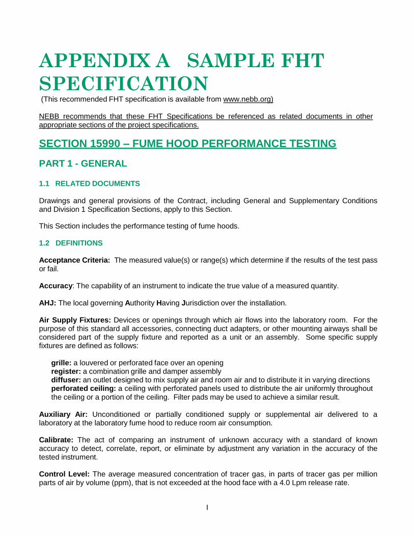
APPENDIX A SAMPLE FHT
SPECIFICATION (This recommended FHT specification is available from www.nebb.org)
NEBB recommends that these FHT Specifications be referenced as related documents in other appropriate sections of the project specifications.
SECTION 15990 – FUME HOOD PERFORMANCE TESTING
PART 1 - GENERAL 1.1 RELATED DOCUMENTS
Drawings and general provisions of the Contract, including General and Supplementary Conditions and Division 1 Specification Sections, apply to this Section.
This Section includes the performance testing of fume hoods.
1.2 DEFINITIONS
Acceptance Criteria: The measured value(s) or range(s) which determine if the results of the test pass or fail.
Accuracy: The capability of an instrument to indicate the true value of a measured quantity.
AHJ: The local governing Authority Having Jurisdiction over the installation.
Air Supply Fixtures: Devices or openings through which air flows into the laboratory room. For the purpose of this standard all accessories, connecting duct adapters, or other mounting airways shall be considered part of the supply fixture and reported as a unit or an assembly. Some specific supply fixtures are defined as follows:
grille: a louvered or perforated face over an opening register: a combination grille and damper assembly diffuser: an outlet designed to mix supply air and room air and to distribute it in varying directions perforated ceiling: a ceiling with perforated panels used to distribute the air uniformly throughout the ceiling or a portion of the ceiling. Filter pads may be used to achieve a similar result.
Auxiliary Air: Unconditioned or partially conditioned supply or supplemental air delivered to a laboratory at the laboratory fume hood to reduce room air consumption.
Calibrate: The act of comparing an instrument of unknown accuracy with a standard of known accuracy to detect, correlate, report, or eliminate by adjustment any variation in the accuracy of the tested instrument.
Control Level: The average measured concentration of tracer gas, in parts of tracer gas per million parts of air by volume (ppm), that is not exceeded at the hood face with a 4.0 Lpm release rate.

NEBB FHT PROCEDURAL STANDARDS APPENDIX A
SAMPLE FHT SPECIFICATION
II
Deficiency: Any circumstance or operation that affects the measurement results as compared to the design criteria required by the contract documents.
Design Sash Opening: The position of the sash at which the design team assumes that the fume hood will be operating.
Face Velocity: The average velocity of air moving perpendicular to the hood face, usually expressed in feet per minute (fpm) or meters per second (m/s).
Fume Hood (sometimes referred to as a laboratory hood): A box-like structure enclosing a source of potential air contamination, normally with one open or partially open side, into which air is moved for the purpose of containing and exhausting air contaminants. A fume hood is generally used for bench-scale laboratory operations but does not necessarily involve the use of a bench or table.
Fume Hood System: An arrangement consisting of a fume hood, its adjacent room environment, and the air exhaust equipment, such as blowers and ductwork, required to make the hood operable.
Function: For the purposes of this NEBB Standard, function refers to the specific type of data measurement specified in Section 4, Standards for Instrumentation and Calibration.
High Value of Range: The maximum response time divided by the average response time of the VAV Response Time Test. Value is expressed as a percentage.
Hood Face: The plane of minimum area at the front portion of a laboratory fume hood through which air enters when the sash(es) is (are) fully opened, usually in the same plane as the sash for a hood with a vertical sash. For a hood with horizontal sash(es) or a combination sash, the hood face is usually the plane passing through the midpoint between the inner and outer sashes.
Lazy Airflow: Airflow within the hood is described as lazy when smoke remains on the work surface without smoothly flowing to the back baffle.
LPM: Liters per minutes.
Low Value of Range: The minimum response time divided by the average response time of the VAV Response Time Test. Value is expressed as a percentage.
May: Used to indicate a course of action that is permissible as determined by the NEBB Certified FHT Firm.
Maximum Sash Opening: The position of the sash at which the fume hood has the largest opening.
N/A: Not Available, Not Applicable, or Not Accessible. The simple notation “N/A” without definition is not allowed.
NEBB Certified FHT Firm: A NEBB Certified FHT Firm is a firm that has met and maintains all the requirements of the National Environmental Balancing Bureau for firm certification in Fume Hood Performance Testing and is currently certified by NEBB. A NEBB Certified FHT Firm shall employ at least one NEBB Certified FHT Professional in a full time management position.
NEBB FHT PROCEDURAL STANDARDS APPENDIX A
SAMPLE FHT SPECIFICATION
3
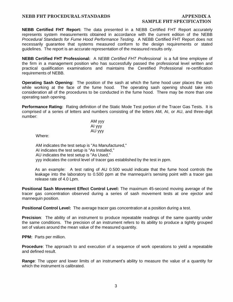
NEBB Certified FHT Report: The data presented in a NEBB Certified FHT Report accurately represents system measurements obtained in accordance with the current edition of the NEBB Procedural Standards for Fume Hood Performance Testing. A NEBB Certified FHT Report does not necessarily guarantee that systems measured conform to the design requirements or stated guidelines. The report is an accurate representation of the measured results only.
NEBB Certified FHT Professional: A NEBB Certified FHT Professional is a full time employee of the firm in a management position who has successfully passed the professional level written and practical qualification examinations and maintains the Ceretified Professional re-certification requirements of NEBB.
Operating Sash Opening: The position of the sash at which the fume hood user places the sash while working at the face of the fume hood. The operating sash opening should take into consideration all of the procedures to be conducted in the fume hood. There may be more than one operating sash opening.
Performance Rating: Rating definition of the Static Mode Test portion of the Tracer Gas Tests. It is comprised of a series of letters and numbers consisting of the letters AM, AI, or AU, and three-digit number:
Where:
AM yyy AI yyy AU yyy
AM indicates the test setup is "As Manufactured," AI indicates the test setup is "As Installed," AU indicates the test setup is "As Used," yyy indicates the control level of tracer gas established by the test in ppm.
As an example: A test rating of AU 0.500 would indicate that the fume hood controls the leakage into the laboratory to 0.500 ppm at the mannequin's sensing point with a tracer gas release rate of 4.0 Lpm.
Positional Sash Movement Effect Control Level: The maximum 45-second moving average of the tracer gas concentration observed during a series of sash movement tests at one ejector and mannequin position.
Positional Control Level: The average tracer gas concentration at a position during a test.
Precision: The ability of an instrument to produce repeatable readings of the same quantity under the same conditions. The precision of an instrument refers to its ability to produce a tightly grouped set of values around the mean value of the measured quantity.
PPM: Parts per million.
Procedure: The approach to and execution of a sequence of work operations to yield a repeatable and defined result.
Range: The upper and lower limits of an instrument’s ability to measure the value of a quantity for which the instrument is calibrated.
NEBB FHT PROCEDURAL STANDARDS APPENDIX A
SAMPLE FHT SPECIFICATION
4
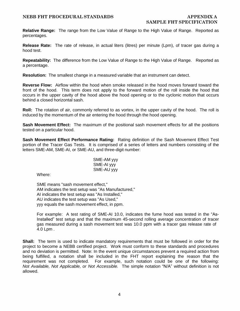
Relative Range: The range from the Low Value of Range to the High Value of Range. Reported as percentages.
Release Rate: The rate of release, in actual liters (litres) per minute (Lpm), of tracer gas during a hood test.
Repeatability: The difference from the Low Value of Range to the High Value of Range. Reported as a percentage.
Resolution: The smallest change in a measured variable that an instrument can detect.
Reverse Flow: Airflow within the hood when smoke released in the hood moves forward toward the front of the hood. This term does not apply to the forward motion of the roll inside the hood that occurs in the upper cavity of the hood above the hood opening or to the cyclonic motion that occurs behind a closed horizontal sash.
Roll: The rotation of air, commonly referred to as vortex, in the upper cavity of the hood. The roll is induced by the momentum of the air entering the hood through the hood opening.
Sash Movement Effect: The maximum of the positional sash movement effects for all the positions tested on a particular hood.
Sash Movement Effect Performance Rating: Rating definition of the Sash Movement Effect Test portion of the Tracer Gas Tests. It is comprised of a series of letters and numbers consisting of the letters SME-AM, SME-AI, or SME-AU, and three-digit number:
Where:
SME-AM yyy SME-AI yyy SME-AU yyy
SME means "sash movement effect," AM indicates the test setup was "As Manufactured," AI indicates the test setup was "As Installed," AU indicates the test setup was "As Used," yyy equals the sash movement effect, in ppm.
For example: A test rating of SME-AI 10.0, indicates the fume hood was tested in the “As- Installed” test setup and that the maximum 45-second rolling average concentration of tracer gas measured during a sash movement test was 10.0 ppm with a tracer gas release rate of 4.0 Lpm .
Shall: The term is used to indicate mandatory requirements that must be followed in order for the project to become a NEBB certified project. Work must conform to these standards and procedures and no deviation is permitted. Note: In the event unique circumstances prevent a required action from being fulfilled, a notation shall be included in the FHT report explaining the reason that the requirement was not completed. For example, such notation could be one of the following: Not Available, Not Applicable, or Not Accessible. The simple notation “N/A” without definition is not allowed.
NEBB FHT PROCEDURAL STANDARDS APPENDIX A
SAMPLE FHT SPECIFICATION
5
Should: The term is used to indicate that a certain course of action is preferred but not necessarily required.
Specified Rating: The hood performance rating as specified, proposed, or guaranteed either in the purchase of the hood or in the design and construction of the laboratory, or both.
Standard: A required qualification, action, or result for FHT work.
Standard Operating Procedure: An internal policy prepared by the each FHT firm and / or prepared by the Owner/Buyer. Procedures are written to provide guidance, direction, and step-by-step details relating to issues such as safety, testing protocols, acceptance criteria, etc. NEBB FHT Firm SOP’s shall be utilized in an absence of SOP’s prepared by the Owner.
Test Sash Opening: The position or positions of the sash at which the fume hood is tested.
Test Setup (Test Setup Mode): Defines the condition of the fume hood being tested. There are three distinct conditions that the fume hood may be tested:
As-Manufactured (AM): With this test setup, the fume hood is tested at the manufacturer’s facility or under conditions that would replicate those conditions. The hood and work surface shall be void of all process equipment, apparatus and chemicals.
As-Installed (AI): With this test setup, the actual fume hood is tested in its installed, operating condition. All supply, exhaust and return air systems are installed, operable and under control. The hood and work surface shall be void of all process equipment, apparatus and chemicals.
As-Used (AU): This test setup is the same as the As-Installed setup except the hood is being utilized for actual process work. Experiment equipment, chemicals and processes are being carried out inside the hood while the fume hood performance testing is being performed. This means that all normal operating equipment within the hood shall be activated and operational including items such as all heat and vapor producing appliances, physical obstructions, etc.
Testing: The use of specialized and calibrated instruments to measure fluid quantities, temperatures, pressures, rotational speeds, electrical characteristics, velocities, and sound and vibration levels,
Testing, Adjusting, and Balancing (TAB): A systematic process or service applied to heating, ventilating and air-conditioning (HVAC) systems and other environmental systems to achieve and document air and hydronic flow rates. The standards and procedures for providing these services are addressed in the current edition of the NEBB “PROCEDURAL STANDARDS FOR THE TESTING, ADJUSTING AND BALANCING OF ENVIRONMENTAL SYSTEMS.”
VAV Speed of Response: The time, measured from the first movement of the sash, for the VAV system to restore the slot velocity or airflow to 90 percent of the average steady-state value.
VAV Time to Steady State: The time, measured from the first movement of the sash, for the VAV system restore and maintain the average slot velocity of airflow between 90 and 110 percent of the average steady-state value.
Work Surface: The surface that the fume hood sets on.
NEBB FHT PROCEDURAL STANDARDS APPENDIX A
SAMPLE FHT SPECIFICATION
6
1.3 FHT FIRM QUALIFICATIONS The FHT Firm shall be NEBB Certified in Fume Hood Performance Testing. The individual conducting the fume performance testing shall be a NEBB Certified FHT Professional.
1.4 FHT FIRM SUBMITTALS
1.4.1 Qualification Data: When requested, submit 2 copies of evidence that the FHT firm and this Project's FHT team members meet the qualifications specified in Sub-section 1.3 FHT Firm Qualifications.
1.4.2 FHT Agenda: When requested, submit 2 copies of the FHT Agenda. Include a complete set of report forms intended for use on this Project.
1.4.3 Certified FHT Reports: Submit a final FHT report in accordance with the current edition of the NEBB Procedural Standards for Fume Hood Performance Testing.
1.5 QUALITY ASSURANCE
1.5.1 The NEBB Certified FHT Firm shall submit 2 copies of the firm's NEBB FHT Certification.
1.5.2 When requested, the NEBB Certified FHT Firm shall provide the NEBB Certificate of Conformance Certification.
1.5.3 FHT Report Forms: Prepare report forms in accordance with the requirements from the current edition of the NEBB Procedural Standards for Fume Hood Performance Testing.
1.5.4 Instrumentation Calibration: Calibration of instruments shall be in accordance with the current edition of the NEBB Procedural Standards for Fume Hood Performance Testing.
1.6 CONSTRUCTION TEAM RESPONSIBILITY TO FHT AGENCY
1.6.1 Provide the NEBB Certified FHT Firm with a conformed set of contract documents (drawings, specifications, and approved submittals), including all current approved change orders/contract modifications.
1.6.2 Develop a project schedule with the input of the NEBB Certified FHT Firm that coordinates the work of other disciplines and provides adequate time in the construction process to allow successful completion of the FHT work.
1.6.3 Notify the NEBB Certified FHT Firm of schedule changes.
1.6.4 Ensure that the building enclosure is complete, including but not limited to, all structural components, windows and doors installed, door hardware complete, ceilings complete, stair, elevator and mechanical shafts complete, roof systems complete, all plenums sealed, etc.
1.6.5 Complete the installation of permanent electrical power systems serving the HVAC equipment and systems. Such systems shall be properly installed in accordance with all applicable codes to ensure the safety of all construction personnel.
1.6.6 Complete the installation of all HVAC equipment and systems to ensure safe operation.
NEBB FHT PROCEDURAL STANDARDS APPENDIX A
SAMPLE FHT SPECIFICATION
VII
1.6.7 Perform the startup of all HVAC equipment and systems in accordance with the manufacturer’s recommendations.
1.6.8 Complete installation, programming (including design parameters and graphics), calibration, and startup of all building control systems.
1.6.9 Verify that the building control system provider has commissioned and documented their work before the FHT work begins.
1.6.10 Require that the building control system firm provide access to hardware and software, or onsite technical support required to assist the FHT effort. The hardware and software or the onsite technical support shall be provided at no cost to the NEBB Certified FHT Firm.
1.6.11 Furnish and install all drive changes as required.
1.6.12 Complete all TAB work prior to performing FHT work.
1.7 FHT INSTRUMENTATION AND EQUIPMENT The FHT Firm shall provide all necessary instrumentation, equipment and appurtenances required to perform the fume hood performance testing. All instrumentation, equipment and appurtenances shall be as indicated in the current edition of the NEBB Procedural Standards for Fume Hood Performance Testing.
PART 2 - PRODUCTS (Not Applicable)
PART 3 – EXECUTION
3.1 EXAMINATION Examine the Contract Documents to become familiar with Project requirements and to discover conditions in systems' designs that may preclude proper FHT of systems and equipment. Contract Documents are defined in the General and Supplementary Conditions of the Contract. Report deficiencies discovered.
The NEBB Certified FHT Firm shall verify that the TAB work is complete and shall review the completed TAB Report prior to performing any fume hood tests.
3.2 GENERAL PROCEDURES FOR FUME HOOD PERFORMANCE TESTING
Perform hood testing on each fume hood indicated to be tested according to the procedures contained in the current edition of the NEBB Procedural Fume Hood Performance Testing and this section.
3.3 TEST SETUP MODE All fume hoods shall be tested in the select one (As-Manufactured, As-Installed or As-Used) test setup mode.
3.4 DESIGN SASH OPENING (The design professional must select the appropriate design sash opening for each hood and each type of hood i.e. horizontal sash, vertical sash, or combination sash. The following may be used as a guide in selecting the design sash opening:

NEBB FHT PROCEDURAL STANDARDS APPENDIX A
SAMPLE FHT SPECIFICATION
8
Vertical Sash 18” above the work surface Horizontal Sash One sash fully open, all other sashes closed(3 sash), or two sashes fully
open and two sashes fully closed( 4 sash) Combination Sash One sash fully open to 18” above the work surface and all other sashes
closed. If the design professional is unsure about selecting the appropriate sash design sash opening, the owner should be consulted. It is imperative to specify the design sash opening, as the fume hood performance tests are based on this sash position.)
The design sash opening shall be _(insert height) ” above the work surface for vertical sash fume hoods, or The design sash opening shall be _(insert number of sashes) sashes open for horizontal sash fume hoods, or The design sash opening shall be __(insert height) ” above the work surface and _(insert number of sashes) open for combination sash fume hoods.
3.5 AIRFLOW VELOCITY TESTS: Constant Air Volume (CAV) Fume Hood
3.5.1 Test Procedures: Airflow Face Velocity Tests
3.5.1.1 Set hood to the design opening sash position or as agreed to by the Owner / Buyer.
Measure the area of the opening. The area shall be determined as follows:
Height shall be based on the dimension from the bottom most part of the sash to the work surface located in a straight plane directly beneath the sash for vertical sashes, or the opening between horizontal tracks on horizontal sashes. Width: Width shall be based on the interior dimensions of the design sash opening.
3.5.1.2 Determine a grid pattern of equal areas by dividing the opening into horizontal and vertical dimensions. Each equal area grid location shall be a maximum of one (1) square foot (0.093 m²) with no dimension larger than 13” (330 mm).
3.5.1.3 Place the instrument on the equipment stand and locate the instrument in the center of each grid location in the plane of the sash opening and normal to the plane. All personnel should stand clear of the hood so as not to affect the airflow.
3.5.1.4 Measure and record the airflow face velocities at the center of each grid location. Each grid location shall have a minimum of 20 samples taken at one second intervals. Average the 20 samples at each location to determine the airflow face velocity at each grid location.
3.5.1.5 The hood airflow face velocity is determined by averaging the airflow face velocity from each grid location. Report the hood average airflow face velocity and the highest and lowest grid location average.
3.5.1.6 If the actual average airflow face velocity as determined above does not meet the acceptance criteria as Section 3.5.2, remedial work, if required, is NOT part of the fume hood testing scope of work. If authorized, the remedial work could be performed by the NEBB Certified FHT Firm as an additional service.

NEBB FHT PROCEDURAL STANDARDS APPENDIX A
SAMPLE FHT SPECIFICATION
9
3.5.1.7 For reference and safety purposes, the fume hood airflow face velocity should also be determined at a full open sash position. The procedure to be followed shall be as previously indicated above.
3.5.1.8 It should be noted that the total fume hood exhaust volume is NOT equal to the average airflow face velocity being captured through the sash opening. Additionally, air may enter the hood through leakage and other openings.
3.5.2 Acceptance Criteria: The acceptance criteria for CAV airflow face velocity shall be select one:
100 fpm ±10 fpm As directed by the Owner / Buyer Define acceptance criteria if other than 100 fpm
3.5.3 Reporting Requirements The following shall be included in the final report:
a. Technician Name b. Date of test c. Sash Configuration d. Design Opening Sash Position (Height and Width) e. Average Airflow Velocity at each grid location (fpm) (m/s) f. Hood average Airflow Face Velocity (fpm) (m/s) g. Test instrumentation h. Acceptance Criteria
3.6 AIRFLOW VELOCITY TESTS: Variable Air Volume (VAV) Fume Hood
3.6.1 Test Procedures: Airflow Face Velocity Tests
3.6.1.1 Set hood to the design opening sash position or as agreed to by the Owner / Buyer. Measure the area of the opening. The area shall be determined as follows:
Height shall be based on the dimension from the bottom most part of the sash to the work surface located in a straight plane directly beneath the sash for vertical sashes, or the opening between horizontal tracks on horizontal sashes. Width: Width shall be based on the interior dimensions of the design sash opening.
3.6.1.2 Determine a grid pattern of equal areas by dividing the opening into horizontal and vertical dimensions. Each equal area grid location shall be a maximum of one (1) square foot (0.093 m²) with no dimension larger than 13” (330 mm).
3.6.1.3 Place the instrument on the equipment stand and locate the instrument in the center of each grid location in the plane of the sash opening and normal to the plane. All personnel should stand clear of the hood so as not to affect the airflow.
3.6.1.4 Measure and record the airflow face velocities at the center of each grid location. Each grid location shall have a minimum of 20 samples taken at one second intervals. Average the 20 samples at each location to determine the airflow face velocity at each grid location.

NEBB FHT PROCEDURAL STANDARDS APPENDIX A
SAMPLE FHT SPECIFICATION
10
3.6.1.5 The hood airflow face velocity is determined by averaging the airflow face velocity from each grid location. Report the hood average airflow face velocity and the highest and lowest grid location average.
3.6.1.6 If the actual average airflow face velocity as determined above does not meet the acceptance criteria as Section 3.4.2, remedial work, if required, is NOT part of the fume hood testing scope of work. If authorized, the remedial work could be performed by the NEBB Certified FHT Firm as an additional service.
3.6.1.7 For reference and safety purposes, the fume hood airflow face velocity should also be determined at a full open sash position. The procedure to be followed shall be as previously indicated above.
3.6.1.8 Reduce the sash position to 50% of the specified opening and repeat airflow face velocity measurements / calculations as described above. Record the average airflow face velocity at the 50% opening position.
3.6.1.9 Reduce the sash position to 25% of the specified opening and repeat airflow face velocity measurements / calculations as described above. Record the average airflow face velocity at the 25% opening position.
3.6.1.10 It should be noted that the total fume hood exhaust volume is NOT equal to the average airflow face velocity being captured through the sash opening. Additionally, air may enter the hood through leakage and other openings.
3.6.2 Test Procedures: Response Test
3.6.2.1 There are two acceptable methods to perform and measure response time: exhaust duct airflow velocity or hood plenum airflow velocity. Determine the baseline and response conditions by either of the following methods:
a. Exhaust duct airflow velocity method: Place the sensing device in a stable (non- turbulent airflow) location of the exhaust duct, or
b. Fume hood plenum airflow velocity method: Place sensing device in the fume hood plenum behind the baffle panel.
3.6.2.2 Measure the velocity at the full sash opening to establish a baseline condition.
3.6.2.3 The Response Time Test involves 3 cycles of opening and closing the sash position from full closed to full open. When changing the sash position, use a smooth continuous motion and move the sash at a rate of approximately 1.5 feet per second (0.45 m/s).
3.6.2.4 Close the sash completely, start velocity measurements recording and leave closed for 30 seconds. Open the sash to full opening for 60 seconds. Close the sash for 30 seconds. Open the sash to full opening for 60 seconds. Close the sash for 30 seconds. Open the sash to full opening for 60 seconds. Close the sash for 30 seconds and stop velocity measurements recording.
3.6.2.5 Measure and record velocity readings at one second intervals.
NEBB FHT PROCEDURAL STANDARDS APPENDIX A
SAMPLE FHT SPECIFICATION
11
3.6.2.6 Measure, record and report the speed of response to first obtain a velocity equal to 90% of baseline condition for each iteration.
3.6.2.7 Measure, record and report the time to maintain the velocity to within ±10% of
baseline condition for each iteration.
3.6.2.8 Perform measurements for all 3 cycles. The procedure stated above applies to either vertical or horizontal sash configurations. For fume hoods with combination sash configurations, the procedure shall be performed both in the vertical and in the horizontal sash opening positions.
3.6.2.9 The repeatability of the results should be analyzed for all three cycles by determining the relative range of the response times for all three cycles. The relative range is the comparison of the lowest response time and highest response time to the average response time. It may be calculated as follows:
3.2.6.9.1 Low Value of Range: Divide the minimum response time by the average
response time. 3.2.6.9.2 High Value of Range: Divide the maximum response time by the average
response time. 3.2.6.9.3 Relative Range: The range from the Low Value of Range to the High Value
of Range. 3.2.6.9.4 Repeatability: The difference from the Low Value of Range to the High Value
of Range
All of the above values shall be reported as percentages.
3.6.3 Acceptance Criteria:
3.6.3.1 The acceptance criteria for VAV airflow face velocity shall be select one: 100 fpm ±10 fpm As directed by the Owner / Buyer Define acceptance criteria if other than 100 fpm
3.6.3.2 The acceptance criteria for average speed of response, individual speed of
responses, individual times to maintain, Low Value of Range, High Value of Range, Relative Range and Repeatability shall be select one: As directed by the Owner / Buyer Define criteria for all of the reporting criteria
3.6.4 Reporting Requirements The following shall be included in the final report:
a. Technician Name b. Date of test c. Sash Configuration d. Design Opening Sash Position (Height and Width) e. Average Airflow Velocity at each grid location (fpm) (m/s) f. Hood average Airflow Face Velocity (fpm) (m/s) g. Test results reported at 25%, 50% and 100% of specified conditions
NEBB FHT PROCEDURAL STANDARDS APPENDIX A
SAMPLE FHT SPECIFICATION
XII
h. Speed of Response (in seconds) (3 cycles) i. Low Value of Range (in percentage) j. High Value of Range (in percentage) k. Relative Range (in percentage) l. Repeatability (in percentage) m. Time to Maintain (in seconds) (3 cycles) n. Test Method (exhaust airflow velocity method or fume hood plenum airflow
velocity method) o. Test instrumentation p. Acceptance Criteria
3.7 AIRFLOW VISUALIZATION TESTS: Local Challenge The purpose of the Local Challenge Test is to provide a visual indication of the fume hood’s capture performance when a small scale challenge is introduced. Coordinate disabling the local fire alarm system when performing this test. Care should be taken to compensate for smoke discharge velocity and exposure outside of the fume hood.
3.7.1 Test Procedures
3.7.1.1 Set the sash position to operating condition as determined by the Airflow Face Velocity Test.
3.7.1.2 Place the smoke source outside the fume hood and under the airfoil. Move along the entire length of the opening. Verify that the smoke is drawn into the hood, properly exhausted and not entrained in a vortex at the top of the hood.
3.7.1.3 Position the smoke source along the sides and bottom of the hood in the sash plane opening. For combination, or horizontal sash fume hoods, pass smoke source along the inside edge of all openings. Verify that the smoke is drawn into the hood and exhausted properly.
3.7.1.4 Place the smoke source 6” (152 mm) inside the hood along the bottom of, and parallel to, the sash. Move along the entire length of the sash bottom. Verify that the smoke is contained within the hood and properly exhausted.
3.7.1.5 Move the smoke source so that it traverses the entire work surface and around internal equipment when applicable. Verify that the smoke is contained within the hood and properly exhausted.
3.7.1.6 Place the smoke source outside the fume hood and determine effects of room and HVAC system conditions by observing the smoke patterns.
3.7.1.7 Place smoke source in cavity above the hood opening and observe the smoke roll inside the hood.
3.7.2 Acceptance Criteria Smoke shall be contained within the fume hood under all test procedures. If the smoke escapes the fume hood under any of the above test procedures, the hood fails and shall be so noted in the report. The NEBB Certified FHT Firm shall immediately notify the Owner / Buyer in writing that the fume hood has failed.
3.7.3 Reporting Requirements
NEBB FHT PROCEDURAL STANDARDS APPENDIX A
SAMPLE FHT SPECIFICATION
13
The following shall be included in the final report: a. Technician Name b. Date of test c. Test State d. Sash Configuration e. Sash Opening Height and Width f. Challenge Medium Used g. Narrative description of actual visual test results including Statement of
Pass/Fail h. Test instrumentation i. Acceptance Criteria
3.8 AIRFLOW VISUALIZATION TESTS: Large Volume Generation The Large Volume Challenge Test SHOULD NOT be performed if the hood failed the Local Challenge Test. The purpose of the Large Volume Challenge Test is to provide a visual indication of the fume hood’s capture performance when a large scale challenge is introduced. The test procedures for the Large Volume Challenge Test are similar to the Local Challenge Test. Coordinate disabling the local fire alarm system when performing this test.
Care should be taken to compensate for smoke discharge velocity and exposure outside of the fume hood.
3.8.1 Test Procedures
3.8.1.1 Set the sash position to operating condition as determined by the Airflow Face Velocity Test.
3.8.1.2 Place the smoke source outside the fume hood and under the airfoil. Move along the entire length of the opening. Verify that the smoke is drawn into the hood, properly exhausted and not entrained in a vortex at the top of the hood.
3.8.1.3 Discharge the smoke source as close to the sash plane as practical for containment and maximum observation time. Position the smoke source along the sides and bottom of the hood. For combination, or horizontal sash fume hoods, pass smoke source along the inside edge of all openings. Verify that the smoke is drawn into the hood and exhausted properly.
3.8.1.4 Discharge the smoke source as close to the sash plane as practical for containment and maximum observation time. Place the smoke source inside the hood along the bottom of, and parallel to, the sash. Verify that the smoke is contained within the hood and properly exhausted.
3.8.1.5 Move the smoke source so that it traverses the entire work surface and around internal equipment when applicable. Verify that the smoke is contained within the hood and properly exhausted.
3.8.1.6 Place the smoke source outside the fume hood and determine effects of room and HVAC system conditions by observing the smoke patterns.
3.8.1.7 Place smoke source in cavity above the hood opening and observe the smoke roll inside the hood.
3.8.1.8 Try to observe smoke patterns for containment tests from the side of the hood face.
NEBB FHT PROCEDURAL STANDARDS APPENDIX A
SAMPLE FHT SPECIFICATION
14
3.8.2 Acceptance Criteria Smoke shall be contained within the fume hood under all test procedures. If the smoke escapes the fume hood under any of the above test procedures, the hood fails and shall be so noted in the report. The NEBB Certified FHT Firm shall immediately notify the Owner / Buyer in writing that the fume hood has failed.
3.8.3 Reporting Requirements The following shall be included in the final report:
a. Technician Name b. Date of test c. Test State d. Sash Configuration e. Sash Opening Height and Width f. Challenge Medium Used g. Narrative description of actual visual test results including Statement of
Pass/Fail h. Test instrumentation i. Acceptance Criteria
3.9 TRACER GAS CONTAINMENT TESTS: Static Mode
3.9.1 Test Procedures 3.9.1.1 Set the sash position to operating condition as determined by the Airflow Face Velocity Test. If the test is performed at conditions other than full open, it is suggested that this test should also be performed at full open sash position to determine the effect of misuse or condition during equipment setup or loading.
3.9.1.2 Perform a background measurement test of the room concentration levels at a representative location. If during the test a steady increase in the sample readings is noted, perform background measurements to assist in determining the source.
3.9.1.3 All dimensions identified below in locating the ejector system are meant to indicate the near edge of the ejector base. The ejector system shall be located 6” (152 mm) behind the sash for all test locations. This places the detection sensor / sensing tube 9” (229 mm) from the ejector. If this location cannot be accomplished due to equipment placement or other obstructions, move the ejector system and move the detection sensor / sensing tube to a suitable location that will maintain the 9” (229 mm) spacing, or as close as possible to the 9” (229 mm) spacing. Use the following method to identify the ejector system locations:
a. Vertical Sash: Three (3) locations are required for fume hood 8’ (2.4 m) or less: 12” (304 mm) from the left wall, 12” (304 mm) from the right wall and in the center. Four (4) locations are required for fume hoods greater than 8’ (2.4 m): 12” (304 mm) from the left wall, 12” (304 mm) left of center line, 12” (304 mm) right of center line and 12” (304 mm) from the right wall. b. Horizontal Sash: Centerline of each maximum opening space as previously determined in the Airflow Velocity Tests. c. Combination Sash: Locations shall be determined by both the vertical and horizontal sash configurations described above.
3.9.1.4 Place the ejector system inside the fume hood at the first location.

NEBB FHT PROCEDURAL STANDARDS APPENDIX A
SAMPLE FHT SPECIFICATION
15
3.9.1.5 The mannequin shall be directly in front of the ejector system at each test location. The detection sensor / sensing tube shall be located in the breathing zone of the mannequin at a distance of 9” (229 mm) from the near edge of the ejector system typically 3” (76 mm) from the face of the sash and 22” (558 mm) above the work surface.
3.9.1.6 Release the tracer gas at the rate as specified in the contract documents or as agreed to between the Owner and the NEBB Certified FHT Firm. If a release rate has not been specified, then the release rate shall be 4 l/m. Wait 30 seconds before taking samples.
3.9.1.7 Record samples every second for a duration of 5 minutes.
3.9.1.8 Proceed to the next test location and repeat procedure. 3.9.1.9 Report all of the individual readings, the average and the peak concentration for each test location.
3.9.1.10 The performance rating is the highest average of the test locations. The Static Mode Performance Rating shall be reported as follows:
AM yyy AI yyy AU yyy
Where yyy is the highest average concentration of the test locations in ppm.
3.9.2 Acceptance Criteria Acceptance ratings for the Static Mode Tests shall be as directed by the Owner / Buyer. Where acceptance ratings have not been defined, the average concentration shall be no greater than those specified in ANSI Z9.5 and shall be as follows:
0.05 ppm for AM at a release rate of 4 l/m 0.10 ppm for AI at a release rate of 4 l/m 0.10 ppm for AU at a release rate of 4 l/m
Results will be evaluated by Owner’s / Buyer’s properly trained personnel for acceptable rating.
3.9.3 Reporting Requirements The following shall be included in the final report:
a. Technician Name b. Date of test c. Test State d. Sash Configuration e. Sash Opening Height and Width f. Room Layout Drawing g. Graphical display of each test h. Tracer Gas Release Rate i. Test Instrumentation j. Report individual readings, the average and peak at each sample location k. Report the Performance Rating and compare to the Acceptance Rating. Tests
results that exceed acceptance ratings shall be noted in the report.
NEBB FHT PROCEDURAL STANDARDS APPENDIX A
SAMPLE FHT SPECIFICATION
16
3.10 TRACER GAS CONTAINMENT TESTS: Sash Movement Effect 3.10.1 Test Procedures
3.10.1.1 All dimensions identified below in locating the ejector system are meant to indicate the near edge of the ejector base. The ejector system shall be located 6” (152 mm) behind the sash and shall be located in the center of the fume hood. This places the detection sensor / sensing tube 9” (228 mm) from the ejector. If this location cannot be accomplished due to equipment placement or other obstructions, move the ejector system and the detection sensor / sensing tube to a suitable location that will maintain the 9” (228 mm) spacing.
3.10.1.2 The mannequin shall be directly in front of the ejector system at each test location. The detection sensor / sensing tube shall be located in the breathing zone of the mannequin at a distance of 9” (228 mm) from the near edge of the ejector system typically 3” (76 mm) from the face of the sash and 22” (558 mm) above the work surface.
3.10.1.3 Release the tracer gas at the rate as specified in the contract documents or as agreed to between the Owner and the NEBB Certified FHT Firm. If a release rate has not been specified, then the release rate shall be 4 l/m.
3.10.1.4 Start with the sash in the closed position for 60 seconds. Open the sash to the same operating position utilized when performing the Static Test as described above. The sash shall remain open for 60 seconds. Close the sash for 60 seconds. Repeat the process for two additional cycles.
3.10.1.5 The sash should be opened and closed with a smooth motion at a rate of 1.0 to 1.5 feet per second (0.30 to 0.45 m/s).
3.10.1.6 For combination hoods, testing shall be performed in both the vertical and in the horizontal positions.
3.10.1.7 Record samples every second continuously for all three cycles.
3.10.1.8 Calculate the 45 second rolling average for each cycle. Record the maximum rolling average associated with each opening of the sash. The Sash Movement Effect Performance Rating shall be reported as follows:
SME – AM yyy SME – AI yyy SME – AU yyy
Where yyy is the maximum rolling average tracer gas concentration in ppm.
3.10.2 Acceptance Criteria Acceptance ratings for the Sash Movement Effect (SME) shall be as directed by the owner / buyer. Report the performance rating as indicated above.
Results will be evaluated by Owner’s/Buyer’s properly trained personnel for acceptable ratings
3.10.3 Reporting Requirements The following shall be included in the final report:
NEBB FHT PROCEDURAL STANDARDS APPENDIX A
SAMPLE FHT SPECIFICATION
XVII
a. Technician Name b. Date of test c. Time of test d. Test State e. Sash Configuration f. Sash Opening Height and Width g. Room Layout Drawing h. Graphical display of each test i. Tracer Gas Release Rate j. Test Instrumentation k. Record the maximum 45 second rolling average associated with each opening of
the sash. l. Report the Sash Movement Performance Rating. m. If Acceptance Rating has been defined, test results that exceed acceptance
rating shall be noted in the report.
3.11 TRACER GAS CONTAINMENT TESTS: Perimeter Scan 3.11.1 Test Procedures
3.11.1.1 Open the sash to the same operating position utilized when performing the Static Test as described above.
3.11.1.2 Place the ejector system in the center of the fume hood.
3.11.1.3 Remove the mannequin from the front of the fume hood. Remove the detection sensor / sensing tube from the mannequin.
3.11.1.4 Release the gas at the rate as specified in the contract documents or as agreed to between the Owner and the NEBB Certified FHT Firm. If a release rate has not been specified, then the release rate shall be 4 l/m. Release the gas for 30 seconds prior to scanning.
3.11.1.5 While holding the detection sensor / sensing tube in your hand, scan the perimeter of the sash opening and below the airfoil at a rate of not more than 3”/sec (76 mm/sec). Detection sensor / sensing tube shall be passed 1” (25 mm) from the outside surface of the fume hood.
3.11.1.6 Record any measurable leakage and report the location and magnitude.
3.11.2 Acceptance Criteria Acceptance ratings for the Perimeter Scan shall be as directed by the Owner / Buyer. Report the results as indicated above.
Results will be evaluated by Owner’s / Buyer’s properly trained personnel for acceptable results.
3.11.3 Reporting Requirements The following shall be included in the final report:
a. Technician Name b. Date of test c. Time of test d. Test State
NEBB FHT PROCEDURAL STANDARDS APPENDIX A
SAMPLE FHT SPECIFICATION
18
e. Sash Configuration f. Sash Opening Height and Width g. Room Layout Drawing h. Graphical display of each test i. Tracer Gas Release Rate j. Test Instrumentation k. Record any measurable leakage l. Report the location and magnitude of the leakage m. If Acceptance Rating has been defined, test results that exceed acceptance
rating shall be noted in the report. 3.12 OTHER TESTS Edit or delete as applicable to project requirements: In addition to variations of standard tests, a stated scope of work may also require the NEBB Certified FHT Firm to perform other supplementary tests such as:
a) Room Airflow Velocity Tests b) Temperature/Humidity Uniformity Tests c) Sound and Vibration Level Tests d) Cross Draft Condition Tests e) Other Tests
If these other tests are required, the test instrumentation, test procedures, acceptance criteria and reporting shall be specified below or as directed by the Owner/Buyer. All costs associated with these tests are to be included with the scope of work. The tests shall be specified in a similar format as utilized above.
3.12.1 Test Procedures
3.12.2 Acceptance Criteria
3.12.3 Reporting Requirements
The following is provided in guidance in specifying these other tests:
3.12.2 ROOM AIRFLOW VELOCITY TESTS Room airflow velocity tests may be performed to determine the velocity pattern(s) of the air being supplied to a space, or the air being returned or exhausted from a space. This test may be utilized as a diagnostic tool when trouble shooting a project where containment enclosures such as fume hoods are not performing adequately due to poor air distribution layout.
When performing this test, the NEBB Certified FHT Firm should follow the procedures and requirements as identified the current edition of the NEBB Procedural Standards for Certified Testing of Cleanrooms.
3.12.3 TEMPERATURE/HUMIDITY UNIFORMITY TESTS Temperature and/or humidity uniformity tests may be performed to determine the temperature and /or humidity gradient that may exist in a space. This test may be utilized as a diagnostic tool when trouble shooting a project where excessive temperature and/or humidity differentials may exist and could effect the results of the process being conducted in a containment enclosure.
NEBB FHT PROCEDURAL STANDARDS APPENDIX A
SAMPLE FHT SPECIFICATION
19
When performing this test, the NEBB Certified FHT Firm should follow the procedures and requirements as identified the current edition of the NEBB Procedural Standards for Certified Testing of Cleanrooms.
3.12.4 SOUND AND VIBRATION LEVEL TESTS Sound level tests may be performed to determine the overall sound pressure levels in an operating space. Vibration level tests may be performed to determine vibration magnitude levels of rotating equipment that may be in or adjacent to an operating space. These tests may be performed as an adjunct test to normal fume hood performance testing or may be used as a diagnostic tool when trouble shooting a project where sound and/or vibration levels may be excessive.
When performing these tests, the NEBB Certified FHT Firm should follow the procedures and requirements as identified the current edition of the NEBB Procedural Standards for Measurement of Sound and Vibration.
3.12.5 CROSS DRAFT CONDITION TESTS Cross draft condition tests may be performed to document the performance of the fume hood’s containment ability when external draft conditions are present. Laboratory / Cleanroom designers and the installing contractors should be aware of the impact of the items such as: a. The location of the fume hood in the space. b. Location of doors whose opening and closing may cause a draft condition. c. The location of overhead supply, return and exhaust air devices may affect the draft conditions d. The relative adjacency of other containment devices.
The NEBB Certified FHT Firm is required to prepare a layout drawing of the space prior to testing the fume hood tracer gas tests (See Section 11.1) that identifies these components. The fume hood performance may be acceptable to the somewhat static conditions described in Sections 9, 10 and 11 while these standard tests are performed and yet may not provide adequate containment when subjected to unusual, or artificially, created conditions. These draft tests may include testing the performance in concert with a cross-draft, down-draft, or back-draft condition. Additionally, a test designed to simulate the action of personnel walking across the face of the hood during its operation may also display an unsafe condition. The purpose of all of these draft tests is to make the owner / operators aware of these influences on a fume hood’s performance.
The scope of work, the acceptance criteria and the reporting shall be in accordance with the requirements of the contract documents or as agreed to between the Owner/Buyer and the NEBB Certified FHT Firm.
3.12.6 OTHER TESTS Other tests may also be performed and reported by the NEBB Certified FHT Firm based on the requirements of the contract documents or as agreed to between the Owner/Buyer and the NEBB Certified FHT Firm.
3.13 FINAL REPORT The final report shall be in accordance with the requirements of the current edition of the NEBB Procedural Standards for the Fume Hood Performance Testing.

NEBB FHT PROCEDURAL STANDARDS APPENDIX A
SAMPLE FHT SPECIFICATION
20