
Apollo2 EVB Revision 1.1 Quick Start Guide - Ambiq...
12
Apollo2 EVB Quick Start Guide QS-A2r1_1-1p00 Page 1 2017 Ambiq Micro, Inc. All rights reserved. Apollo2 EVB Revision 1.1 Quick Start Guide Doc. ID: QS-A2r1_1-1p00 Document Revision 1.0 Aug 2017
Transcript of Apollo2 EVB Revision 1.1 Quick Start Guide - Ambiq...
Apollo2 EVB Quick Start Guide
QS-A2r1_1-1p00 Page 1 2017 Ambiq Micro, Inc.All rights reserved.
Apollo2 EVB Revision 1.1
Quick Start Guide
Doc. ID: QS-A2r1_1-1p00
Document Revision 1.0
Aug 2017

Apollo2 EVB Quick Start Guide
QS-A2r1_1-1p00 Page 2 2017 Ambiq Micro, Inc.All rights reserved.
Table of Content
Introduction ................................................................................................................. 5Document Revision History......................................................................................... 5Overview of the Apollo2 EVB...................................................................................... 6Debug Interface .......................................................................................................... 7Software Development Tools for the Apollo2 EVB ..................................................... 9Power Supply Options and Measuring Current......................................................... 10

Apollo2 EVB Quick Start Guide
QS-A2r1_1-1p00 Page 3 of 3 2017 Ambiq Micro, Inc.All rights reserved.
List of Figures
Apollo2 EVB, Revision 1.1 .......................................................................................... 6Apollo2 EVB using On-board J-Link Debugger........................................................... 7Apollo2 EVB’s Cortex DEBUG IN Header (J1) ........................................................... 7Apollo2 EVB’s DEBUG OUT Header (J2)................................................................... 8Voltage Selection on Header P19............................................................................. 10Header P19 Configured for 3.3V Operation - No Current Measurement .................. 11Header P19 Configured for 3.3V Operation - With Current Measurement ............... 11

Apollo2 EVB Quick Start Guide
QS-A2r1_1-1p00 Page 4 2017 Ambiq Micro, Inc.All rights reserved.
List of Tables
Document Revision History......................................................................................... 5Jumper Configuration for Power Selections.............................................................. 10

Apollo2 EVB Quick Start Guide
1. Introduction
This document provides guidance in setting up the Apollo2 Evaluation Board (EVB), revision 1.1, to getstarted executing code examples, measuring power consumption in various configurations, and beginningsoftware development.
2. Document Revision History
Rev # Date Description
1.0 Aug 2017 Document initial public release
Table 1: Document Revision History
QS-A2r1_1-1p00 Page 5 2017 Ambiq Micro, Inc.All rights reserved.

Apollo2 EVB Quick Start Guide
3. Overview of the Apollo2 EVB
The Apollo2 EVB features Arduino-compatible headers and an integrated J-Link debugger:
Figure 1. Apollo2 EVB, Revision 1.1
The EVB has these additional features:
▪ Low power reference design▪ Apollo2 MCU in the BGA package (AMAPH1KK-KBR)▪ Multiple power/clock options▪ Micro USB connector for power/download/debug▪ Segger J-Link debugger▪ Debugger-in / debugger-out ports▪ Five user-controlled LEDs▪ Three push buttons for application use, plus a reset push button▪ Power slide switch with LED power indicator▪ Five 8-12 pin Arduino-style headers for pin/power access to shield board(s)▪ Multiple test points for power measurements▪ CE Mark and RoHS compliant
QS-A2r1_1-1p00 Page 6 2017 Ambiq Micro, Inc.All rights reserved.

Apollo2 EVB Quick Start Guide
4. Debug Interface
Figure 2 shows the Apollo2 EVB set up for standard debug using the on-board J-Link debugger and on-board power supply configured for 3.3V.
Figure 2. Apollo2 EVB using On-board J-Link Debugger
The debug interface is supported by standard J-Link drivers from Segger. Please refer to “SoftwareDevelopment Tools for the Apollo2 EVB” on page 9 for more details on J-Link debug support.
This EVB also supports the use of an external Cortex SWD debug interface through a standard 10-pindebug header (DEBUG IN - J1) as shown in Figure 3.
Figure 3. Apollo2 EVB’s Cortex DEBUG IN Header (J1)
QS-A2r1_1-1p00 Page 7 2017 Ambiq Micro, Inc.All rights reserved.

Apollo2 EVB Quick Start Guide
No jumper changes are required to use an external debug adapter. Simply connect the external debugadapter with a 10-pin ribbon cable connector to the “DEBUG IN” header.
The EVB also offers the ability to be used as a J-Link debug adapter for any target board that has anApollo family MCU (Apollo1 or Apollo2).
Figure 4. Apollo2 EVB’s DEBUG OUT Header (J2)
To utilize this functionality, use a 10-pin low-pitch standard debug connector to connect the “DEBUG OUT”header (J2) on the EVB to the debug header on the target board. The EVB will automatically detect whenthe “DEBUG OUT” header is connected to another target board and reconfigure the integrated J-Link toconnect to this external board rather than the onboard Apollo2.
Note: A voltage on pin 1 of the J2 header is required for the above mentioned automatic switch to occur.Also, if the target VDD doesn't match the onboard voltage (either 3.3V or 2.1V), and to avoid possiblevoltage level conflicts on the debug I/O port, VDDIO of the J-Link processor may need to be changed to thetarget voltage by cutting SB5 and shorting SB6.
.
QS-A2r1_1-1p00 Page 8 2017 Ambiq Micro, Inc.All rights reserved.
Apollo2 EVB Quick Start Guide
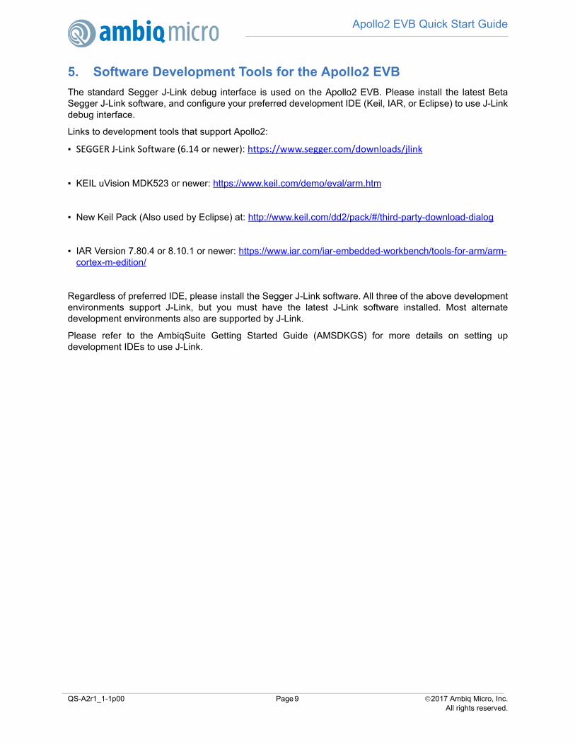
5. Software Development Tools for the Apollo2 EVB
The standard Segger J-Link debug interface is used on the Apollo2 EVB. Please install the latest BetaSegger J-Link software, and configure your preferred development IDE (Keil, IAR, or Eclipse) to use J-Linkdebug interface.
Links to development tools that support Apollo2:
▪ SEGGER J-Link Software (6.14 or newer): https://www.segger.com/downloads/jlink
▪ KEIL uVision MDK523 or newer: https://www.keil.com/demo/eval/arm.htm
▪ New Keil Pack (Also used by Eclipse) at: http://www.keil.com/dd2/pack/#/third-party-download-dialog
▪ IAR Version 7.80.4 or 8.10.1 or newer: https://www.iar.com/iar-embedded-workbench/tools-for-arm/arm-cortex-m-edition/
Regardless of preferred IDE, please install the Segger J-Link software. All three of the above developmentenvironments support J-Link, but you must have the latest J-Link software installed. Most alternatedevelopment environments also are supported by J-Link.
Please refer to the AmbiqSuite Getting Started Guide (AMSDKGS) for more details on setting updevelopment IDEs to use J-Link.
QS-A2r1_1-1p00 Page 9 2017 Ambiq Micro, Inc.All rights reserved.
Apollo2 EVB Quick Start Guide
6. Power Supply Options and Measuring Current
There are three power supply options for the Apollo1 EVB:
▪ Operate at 3.3V as provided by the onboard power supply▪ Operate at 2.1V as provided by the onboard power supply▪ Provide externally supplied power
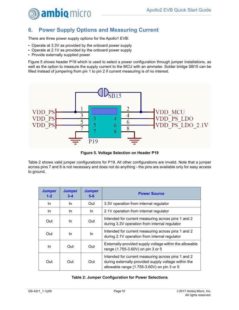
Figure 5 shows header P19 which is used to select a power configuration through jumper installations, aswell as the option to measure the supply current to the MCU with an ammeter. Solder bridge SB15 can befilled instead of jumpering from pin 1 to pin 2 if current measuring is of no interest.
Figure 5. Voltage Selection on Header P19
Table 2 shows valid jumper configurations for P19. All other configurations are invalid. Note that a jumperacross pins 7 and 8 is not necessary and does not do anything - the pins are available only for easy accessto ground.
Table 2: Jumper Configuration for Power Selections
Jumper 1-2
Jumper 3-4
Jumper 5-6
Power Source
In In Out 3.3V operation from internal regulator
In In In 2.1V operation from internal regulator
Out In OutIntended for current measuring across pins 1 and 2 during 3.3V operation from internal regulator
Out In InIntended for current measuring across pins 1 and 2 during 2.1V operation from internal regulator
In Out OutExternally-provided supply voltage within the allowable range (1.755-3.60V) on pin 3 or 5
Out Out OutIntended for current measuring across pins 1 and 2 during externally-provided supply voltage within the allowable range (1.755-3.60V) on pin 3 or 5
QS-A2r1_1-1p00 Page 10 2017 Ambiq Micro, Inc.All rights reserved.
Apollo2 EVB Quick Start Guide
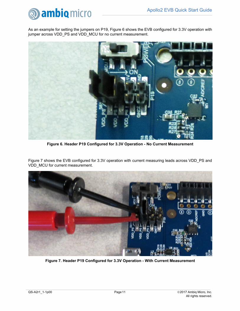
As an example for setting the jumpers on P19, Figure 6 shows the EVB configured for 3.3V operation withjumper across VDD_PS and VDD_MCU for no current measurement.
Figure 6. Header P19 Configured for 3.3V Operation - No Current Measurement
Figure 7 shows the EVB configured for 3.3V operation with current measuring leads across VDD_PS andVDD_MCU for current measurement.
Figure 7. Header P19 Configured for 3.3V Operation - With Current Measurement
QS-A2r1_1-1p00 Page 11 2017 Ambiq Micro, Inc.All rights reserved.

Apollo2 EVB Quick Start Guide
QS-A2r1_1-1p00 Page 12 of 12 2017 Ambiq Micro, Inc.All rights reserved.
Contact Information
Address Ambiq Micro, Inc.
6500 River Place Blvd.
Building 7, Suite 200
Austin, TX 78730-1156
Phone +1 (512) 879-2850
Website http://www.ambiqmicro.com/
General Information [email protected]
Sales [email protected]
Technical Support [email protected]
Legal Information and DisclaimersAMBIQ MICRO INTENDS FOR THE CONTENT CONTAINED IN THE DOCUMENT TO BE ACCURATE AND RELIABLE. THIS CONTENT MAY, HOW-EVER, CONTAIN TECHNICAL INACCURACIES, TYPOGRAPHICAL ERRORS OR OTHER MISTAKES. AMBIQ MICRO MAY MAKE CORRECTIONSOR OTHER CHANGES TO THIS CONTENT AT ANY TIME. AMBIQ MICRO AND ITS SUPPLIERS RESERVE THE RIGHT TO MAKE CORRECTIONS,MODIFICATIONS, ENHANCEMENTS, IMPROVEMENTS AND OTHER CHANGES TO ITS PRODUCTS, PROGRAMS AND SERVICES AT ANY TIMEOR TO DISCONTINUE ANY PRODUCTS, PROGRAMS, OR SERVICES WITHOUT NOTICE.
THE CONTENT IN THIS DOCUMENT IS PROVIDED "AS IS". AMBIQ MICRO AND ITS RESPECTIVE SUPPLIERS MAKE NO REPRESENTATIONSABOUT THE SUITABILITY OF THIS CONTENT FOR ANY PURPOSE AND DISCLAIM ALL WARRANTIES AND CONDITIONS WITH REGARD TOTHIS CONTENT, INCLUDING BUT NOT LIMITED TO, ALL IMPLIED WARRANTIES AND CONDITIONS OF MERCHANTABILITY, FITNESS FOR APARTICULAR PURPOSE, TITLE AND NON-INFRINGEMENT OF ANY THIRD PARTY INTELLECTUAL PROPERTY RIGHT.
AMBIQ MICRO DOES NOT WARRANT OR REPRESENT THAT ANY LICENSE, EITHER EXPRESS OR IMPLIED, IS GRANTED UNDER ANY PAT-ENT RIGHT, COPYRIGHT, MASK WORK RIGHT, OR OTHER INTELLECTUAL PROPERTY RIGHT OF AMBIQ MICRO COVERING OR RELATING TOTHIS CONTENT OR ANY COMBINATION, MACHINE, OR PROCESS TO WHICH THIS CONTENT RELATE OR WITH WHICH THIS CONTENT MAYBE USED.
USE OF THE INFORMATION IN THIS DOCUMENT MAY REQUIRE A LICENSE FROM A THIRD PARTY UNDER THE PATENTS OR OTHER INTEL-LECTUAL PROPERTY OF THAT THIRD PARTY, OR A LICENSE FROM AMBIQ MICRO UNDER THE PATENTS OR OTHER INTELLECTUAL PROP-ERTY OF AMBIQ MICRO.
INFORMATION IN THIS DOCUMENT IS PROVIDED SOLELY TO ENABLE SYSTEM AND SOFTWARE IMPLEMENTERS TO USE AMBIQ MICROPRODUCTS. THERE ARE NO EXPRESS OR IMPLIED COPYRIGHT LICENSES GRANTED HEREUNDER TO DESIGN OR FABRICATE ANY INTE-GRATED CIRCUITS OR INTEGRATED CIRCUITS BASED ON THE INFORMATION IN THIS DOCUMENT. AMBIQ MICRO RESERVES THE RIGHTTO MAKE CHANGES WITHOUT FURTHER NOTICE TO ANY PRODUCTS HEREIN. AMBIQ MICRO MAKES NO WARRANTY, REPRESENTATIONOR GUARANTEE REGARDING THE SUITABILITY OF ITS PRODUCTS FOR ANY PARTICULAR PURPOSE, NOR DOES AMBIQ MICRO ASSUMEANY LIABILITY ARISING OUT OF THE APPLICATION OR USE OF ANY PRODUCT OR CIRCUIT, AND SPECIFICALLY DISCLAIMS ANY AND ALLLIABILITY, INCLUDING WITHOUT LIMITATION CONSEQUENTIAL OR INCIDENTAL DAMAGES. “TYPICAL” PARAMETERS WHICH MAY BE PRO-VIDED IN AMBIQ MICRO DATA SHEETS AND/OR SPECIFICATIONS CAN AND DO VARY IN DIFFERENT APPLICATIONS AND ACTUAL PERFOR-MANCE MAY VARY OVER TIME. ALL OPERATING PARAMETERS, INCLUDING “TYPICALS” MUST BE VALIDATED FOR EACH CUSTOMERAPPLICATION BY CUSTOMER’S TECHNICAL EXPERTS. AMBIQ MICRO DOES NOT CONVEY ANY LICENSE UNDER NEITHER ITS PATENTRIGHTS NOR THE RIGHTS OF OTHERS. AMBIQ MICRO PRODUCTS ARE NOT DESIGNED, INTENDED, OR AUTHORIZED FOR USE AS COMPO-NENTS IN SYSTEMS INTENDED FOR SURGICAL IMPLANT INTO THE BODY, OR OTHER APPLICATIONS INTENDED TO SUPPORT OR SUSTAINLIFE, OR FOR ANY OTHER APPLICATION IN WHICH THE FAILURE OF THE AMBIQ MICRO PRODUCT COULD CREATE A SITUATION WHEREPERSONAL INJURY OR DEATH MAY OCCUR. SHOULD BUYER PURCHASE OR USE AMBIQ MICRO PRODUCTS FOR ANY SUCH UNINTENDEDOR UNAUTHORIZED APPLICATION, BUYER SHALL INDEMNIFY AND HOLD AMBIQ MICRO AND ITS OFFICERS, EMPLOYEES, SUBSIDIARIES,AFFILIATES, AND DISTRIBUTORS HARMLESS AGAINST ALL CLAIMS, COSTS, DAMAGES, AND EXPENSES, AND REASONABLE ATTORNEYFEES ARISING OUT OF, DIRECTLY OR INDIRECTLY, ANY CLAIM OF PERSONAL INJURY OR DEATH ASSOCIATED WITH SUCH UNINTENDEDOR UNAUTHORIZED USE, EVEN IF SUCH CLAIM ALLEGES THAT AMBIQ MICRO WAS NEGLIGENT REGARDING THE DESIGN OR MANUFAC-TURE OF THE PART.