Antenna design using HFSS - Islamic University of...
26
Antenna design using HFSS Prepared by: Mohammed K. Abu Foul 120090710 Supervisor Dr. Mohammed Ouda
Transcript of Antenna design using HFSS - Islamic University of...

Antenna design using HFSS
Prepared by:
Mohammed K. Abu Foul
120090710
SupervisorDr. Mohammed Ouda

CONTENTS
4/19/2011 Islamic University of Gaza 2
Post process
Introduction
Getting results
Conclusion

Introduction
4/19/2011 Islamic University of Gaza 3
HFSS is high-performance full-wave
electromagnetic (EM) field simulator for arbitrary 3D
volumetric passive device modeling that takes advantage
of the familiar Microsoft Windows graphical user
interface.
It can be used to design antenna which it is our scope in
our course.

Introduction
4/19/2011 Islamic University of Gaza 4
To design an antenna using HFSS, you need:
1) Draw the geometry of the antenna
2) Determine the boundaries.
3) Determine Excitation.
4) Perform some post processes, such that:
• Add solution setup (specify the operating frequency)
• Insert far field setup.
• Add frequency sweep. (Range of the solution)
5) Validation check.
6) Analysis all.
Introduction
4/19/2011 Islamic University of Gaza 5
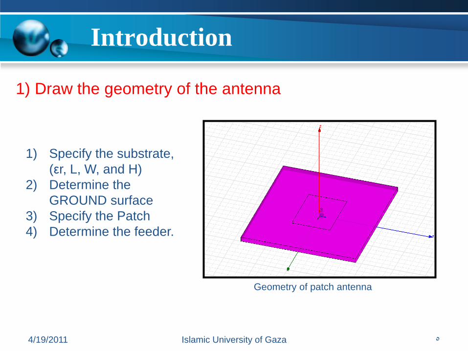
1) Draw the geometry of the antenna
1) Specify the substrate,
(εr, L, W, and H)
2) Determine the
GROUND surface
3) Specify the Patch
4) Determine the feeder.
Geometry of patch antenna

Introduction
4/19/2011 Islamic University of Gaza 6
1) Draw the geometry of the antenna
Geometry of patch antenna

Introduction
4/19/2011 Islamic University of Gaza 7
2) Determine the boundaries
Boundaries of patch antenna

Introduction
4/19/2011 Islamic University of Gaza 8
2) Determine the boundaries
• PerfE_inf_GND

Introduction
4/19/2011 Islamic University of Gaza 9
2) Determine the boundaries
• PerfE_patch
Introduction
4/19/2011 Islamic University of Gaza 10
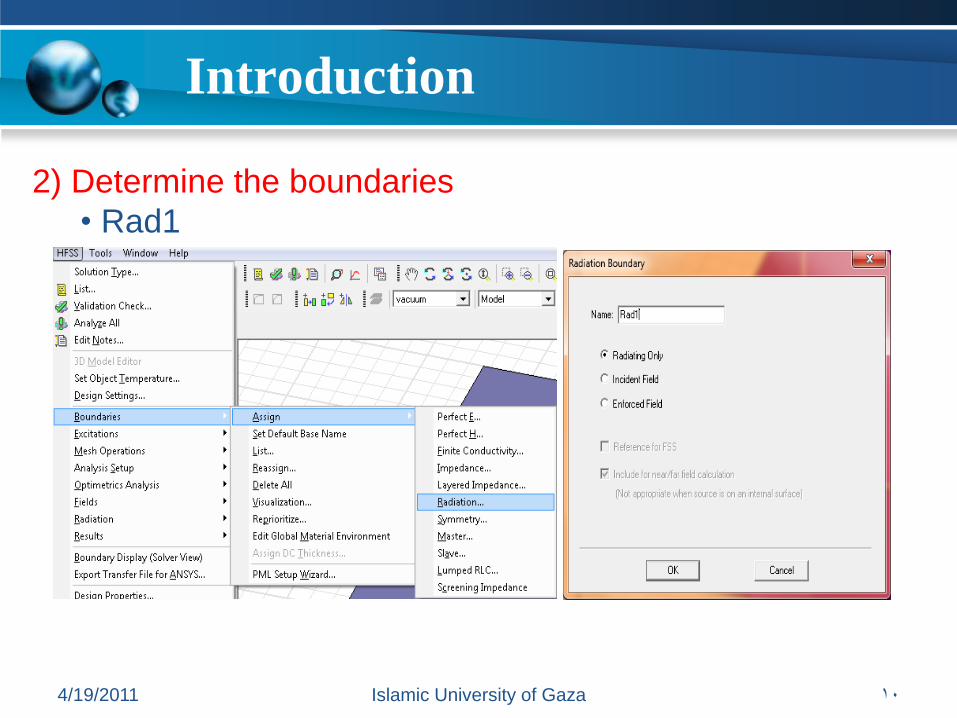
2) Determine the boundaries
• Rad1

Introduction
4/19/2011 Islamic University of Gaza 11
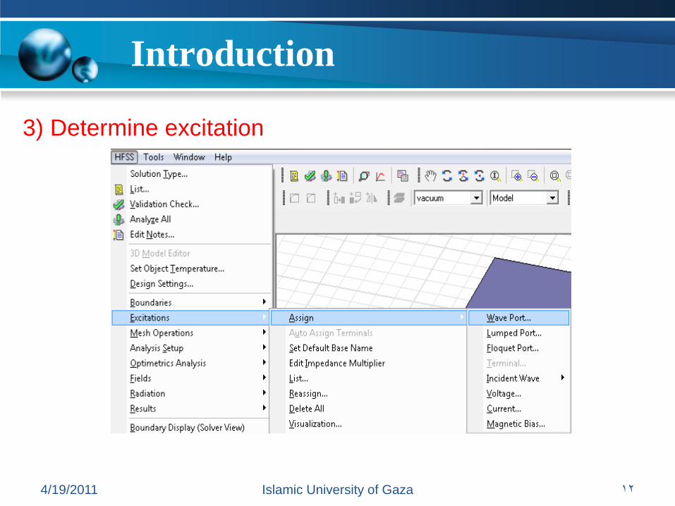
3) Determine excitation
Excitation of patch antenna
Introduction
4/19/2011 Islamic University of Gaza 12
3) Determine excitation

Post processes
4/19/2011 Islamic University of Gaza 13
• Add solution setup

Post processes
4/19/2011 Islamic University of Gaza 14
• Insert far field setup

Post processes
4/19/2011 Islamic University of Gaza 15
• Insert far field setup

Post processes
4/19/2011 Islamic University of Gaza 16
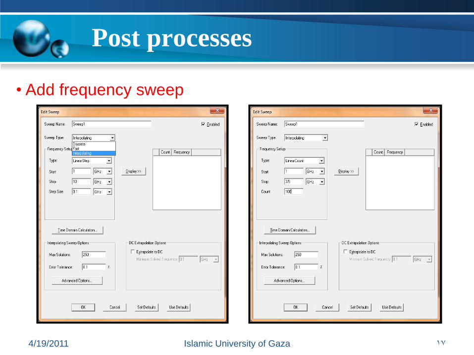
• Add frequency sweep
Post processes
4/19/2011 Islamic University of Gaza 17
• Add frequency sweep

Post processes
4/19/2011 Islamic University of Gaza 18
5) Validation check
Post processes
4/19/2011 Islamic University of Gaza 19
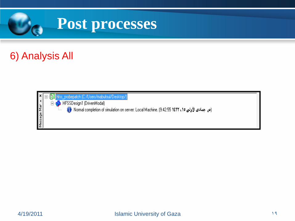
6) Analysis All

Getting results
4/19/2011 Islamic University of Gaza 20

Getting results
4/19/2011 Islamic University of Gaza 21
• 3D plot

Getting results
4/19/2011 Islamic University of Gaza 22
• 3D plot
Getting results
4/19/2011 Islamic University of Gaza 23
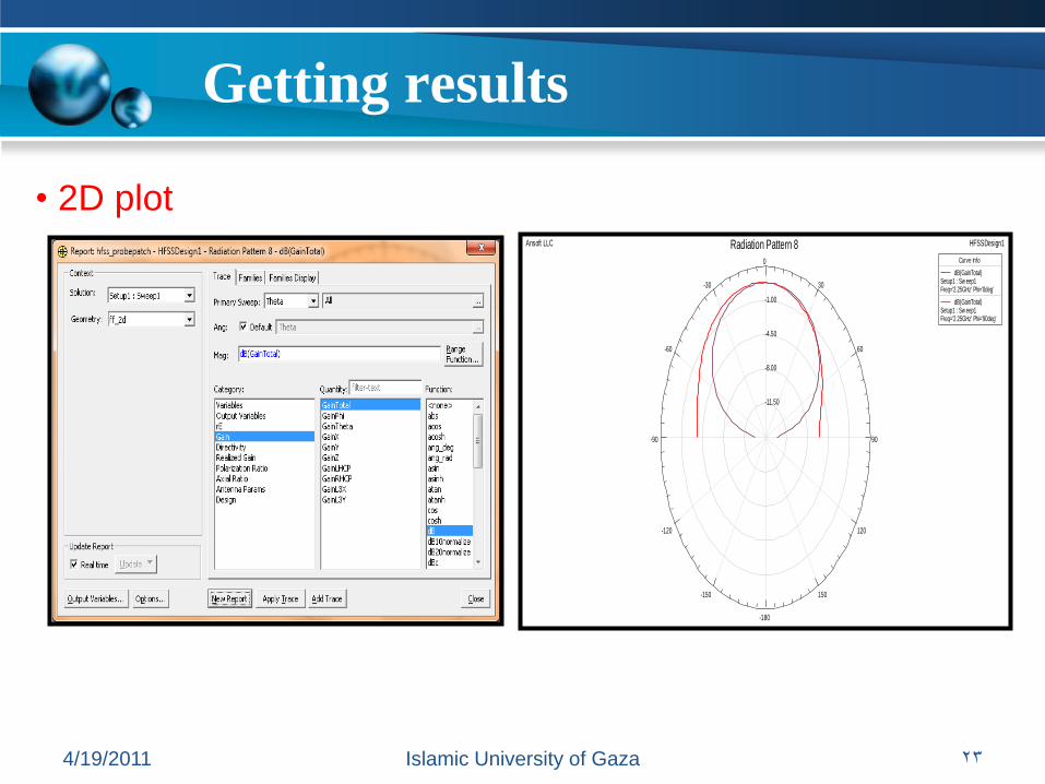
• 2D plot
-11.50
-8.00
-4.50
-1.00
90
60
30
0
-30
-60
-90
-120
-150
-180
150
120
Ansoft LLC HFSSDesign1Radiation Pattern 8Curve Info
dB(GainTotal)Setup1 : Sw eep1Freq='2.25GHz' Phi='0deg'
dB(GainTotal)Setup1 : Sw eep1Freq='2.25GHz' Phi='90deg'

Getting results
4/19/2011 Islamic University of Gaza 24
• 2D plot (rectangular plot)
-100.00 -75.00 -50.00 -25.00 0.00 25.00 50.00 75.00 100.00Theta [deg]
-14.00
-12.00
-10.00
-8.00
-6.00
-4.00
-2.00
0.00
2.00
dB
(Ga
inT
ota
l)
Ansoft LLC HFSSDesign1XY Plot 1Curve Info
dB(GainTotal)Setup1 : Sw eep1Freq='2.25GHz' Phi='0deg'
dB(GainTotal)Setup1 : Sw eep1Freq='2.25GHz' Phi='90deg'

Conclusion
4/19/2011 Islamic University of Gaza 25
*) You can get the result that you want by clicking on the
parameter that you want to get.
*) Try to draw your antenna by yourself.
*) you can discuss your result by comprise it with your paper, or
according to your system consideration.

4/19/2011 Islamic University of Gaza 26
The End


![HFSS Theory[1]](https://static.fdocuments.net/doc/165x107/551489644a7959b1478b4938/hfss-theory1.jpg)