
Analysis of cooling channelsperformance · PDF fileAnalysis of cooling ... The die casting...
18
•
Transcript of Analysis of cooling channelsperformance · PDF fileAnalysis of cooling ... The die casting...
Loughborough UniversityInstitutional Repository
Analysis of cooling channelsperformance
This item was submitted to Loughborough University's Institutional Repositoryby the/an author.
Citation: NORWOOD, A.J. ... et al., 2004. Analysis of cooling channelsperformance. International Journal of Computer Integrated Manufacturing,17(8), pp. 669 - 678
Additional Information:
• This is a preprint of an article published in the journal, InternationalJournal of Computer Integrated Manufacturing [ c© Taylor & Fran-cis]. The definitive version: NORWOOD, A.J....et al., 2004. Anal-ysis of cooling channels performance. International Journal of Com-puter Integrated Manufacturing, 17(8), pp. 669 - 678, is available at:http://dx.doi.org/10.1080/0951192042000237528
Metadata Record: https://dspace.lboro.ac.uk/2134/4649
Version: Submitted for publication
Please cite the published version.

This item was submitted to Loughborough’s Institutional Repository (https://dspace.lboro.ac.uk/) by the author and is made available under the
following Creative Commons Licence conditions.
For the full text of this licence, please go to: http://creativecommons.org/licenses/by-nc-nd/2.5/

1
Analysis of Cooling Channels Performance for Cycle Time
Reduction Using Rapid Manufacturing Techniques and
Computational Fluid Dynamic Analysis
A. J. Norwood1, P. M. Dickens1, R. C. Soar1, R. Harris1 G. Gibbons2, R. Hansell2
1The Rapid Manufacturing Research Group, Wolfson School of Mechanical and Manufacturing
Engineering, Loughborough University, Leicestershire, LE11 3TU, UK 2Warwick Manufacturing Group, Advanced Technology Centre, University of Warwick, Coventry,
CV4 7AL, UK
Abstract: The die casting industry is under increasing pressure to improve production
rates to enable greater productivity. The potential to decrease the cycle time is of great
significance. A small reduction in the cycle time can significantly improve production rates.
Employing conformal cooling channels allows improvements to be made to die
performance through the reduction of solidification times. The paper reviews simulated
solidification results from a traditional cooling channel design and a conformal cooling
channel design. The paper continues by describing the construction of bonded laminate
insert with integrated cooling channels. Casting trials were conducted using the inserts to
validate the simulated results. Work to date has demonstrated the ability to manufacture
laminate inserts quickly, the accuracy of computational fluid dynamics and the importance
of conformal cooling design.
Keywords: Computational fluid dynamics, computer simulation, rapid tooling, laminate
tooling, pressure die-casting, conformal cooling, cycle time reduction

2
1 INTRODUCTION
The cooling of mould tools is crucial to the performance of tooling, it effects both production
rates and component quality [1].
The rapid prototyping industry employs layer methods of manufacturing that allow virtually any
geometry to be physically constructed [2]. Due to this versatility, engineers are able to design
and build complex components with internal features such as conformal cooling channels.
Conformal cooling is achieved by creating a cooling channel that follows the exact contours of
the mould cavity. By having the cooling channels uniformly located around the cavity, the risk of
hot spots is virtually eliminated since the die is uniformly cooled this has been reported to
produce less stressed parts in injection moulding. The increased effect of conformal cooling
also helps to reduce cycle times, which in turn results in increased production rates. Conformal
cooling lines of high complexity can be created [3]. Currently tooling is cooled through straight
interconnecting channels. This traditional method is less than optimal because the passages
can only be directed at right angles and cannot be optimally placed next to those strategic areas
that need cooling. The result is a slower cycle time for the production of parts.
Various methods exist to produce tools containing conformal cooling, such as laser sintering,
spray metal tooling [4], laser caving, wiba & keltool etc. However, laminate tooling could offer
higher strength and toughness than the materials currently used in traditional layered
manufacturing [5]. Laminate tooling is a typical layer by layer manufacturing process requiring a
3D STL CAD file which is then sliced into layers. This sliced data is used to laser cut the
individual laminates form sheet tool steel, these are then brazed together to form a die. The die
surfaces are finished by either electrical discharge machining or high speed machining to
remove the stepping effect created by layer manufacturing. Laminate tool manufacture allows a
die to be constructed from die steel with the benefit of integrated conformal cooling as appose
to a solid H13 die where only straight cooling channels can be machined.
Software such as MAGMASOFT now offer the die designer the ability to model tools and
predict areas of concern and calculate mould fill times. The introduction of conformal cooling
channels within tool design reduces the constraints / compromises made regarding cooling, as
they can be placed exactly where required [6].

3
2 AIMS AND OBJECTIVES
It is the intention of this research to explore the benefits conformal cooling may have on
aluminium (LM24) pressure die-casting cycle times.
The main objectives of this research were:
(a) to conduct a simulation to compare a traditional cooling design against a conformal
cooling design.
(b) to validate the simulation results by conducting die casting trials.
This paper presents the results from the first part of this effort, which was to make a direct
comparison between simulated solidification times of a traditionally cooled die insert and a
conformally cooled die insert. MAGMASOFT® simulation software was employed for this task.
The results were then verified by conducting casting solidification trials using traditionally and
conformally cooled insets. The casting used for the case study, shown in Figure 1 was chosen
as it is representative of a typical commercial aluminium die cast tool that would be run at high
production speeds. The tool was supplied by Dyson Ltd through Kemlows Diecasting Products
Ltd.
Future research will consider different cooling channel geometry and the effect that complex die
geometries have on cooling performance employing both simulation and insert manufacture to
verify results.
Figure 1 Cast aluminium (LM24) clutch housing component
Component Runner Biscuit

4
3 EXPERIMENTAL METHODOLOGY
Two tests were designed to evaluate the efficiency of traditional cooling and conformal cooling.
The biscuit area shown in Figure 1 was chosen as the focus of the research. This area of a tool
is typically more affective by wear, temperature, pressure etc. It is also the last area to solidify
since it feeds aluminium to the casting as it solidified reducing shrinkage. It was the intention to
show that increasing the amount of cooling in the runner system could reduce solidification time
and in turn, reduce the cycle time.
3.1 Conformal Cooling Design
The initial stages was the design of the conformal cooling channel that followed the profile of the
runner in the biscuit area. A 3D STL CAD model was created using Materialise Magics software
of the inserts, one traditional cooled and the other conformal cooled as shown in Figure 2
Figure 2 Biscuit and runner insert design for traditional cooling (left)
and conformal cooling (right)
The diameter of the cooling lines in both were set at 10mm. The conformal cooling channel
design shown in Figure 2 had a ‘M’ profile following the runner and biscuit area. By introducing
a larger cooled area in the biscuit region (1½ times larger) it was envisaged that the inserts
cooling efficiency would increase due to the increased surface area of the cooling channel and
water volume.

5
3.2 Magmasoft Simulation
Simulation was used to determine if a difference in time to solidification could be determined
between the two cooling designs. Analysis of the die was conducted using MAGMASOFT®
software.
Figure 3 Male and female STL CAD of inserts
In order to conduct the simulation the remainder of the tool inserts were modelled shown in
Figure 3. All the STL CAD files were then combined, one with traditional cooling and the other
with conformal cooling shown in Figure 4. These were then imported into the MAGMASOFT®
pre-processor.
Figure 4 3D CAD models of the inserts and shot sleeve used for simulation
Half the model was removed as the die was symmetrical allowing a reduction in processing
time, the model was then meshed. Die cycling temperature and water cooling were simulated.
Figure 5 shows ten theoretical thermocouples that were positioned in the model, starting at the
plunger tip spaced evenly through the insert, casting and cooling channel. The simulation was
cycled 10 times to achieve 'near' steady state. The temperature of each thermocouple was
recorded on the 11th cycle in a graphical format showing the time taken for the component to

6
solidify. Approximately 8.5 temperature readings were recorded / thermocouple / second.
Thermocouple 1 was located at the end of the plunger tip stroke, thermocouple 2, 3, 4 were
located in the biscuit area of the casting, thermocouple 5, 6, 7, 8 were located in the insert and
thermocouple 9, 10 were located in the cooling channel.
Figure 5 Section through the tool showing the location of thermocouple points.
3.3 Casting Validation
Tool inserts were manufactured and ran at production rates to validate the simulated
solidification results. The aim was to reduce the solidification time to achieve a burst biscuit. A
burst biscuit is where a casting has had insufficient time to fully solidify shown in Figure 6. In
pressure die casting the biscuit is situated at the start of the runner system shown in Figure 7. It
feeds the casting and is usually the thickest part, making it the last area to solidify. By
decreasing the solidification time it is possible to create what is called a “burst biscuit” which is
where molten metal in the centre of the biscuit forces its way through a skin of solidified
material. By achieving a burst biscuit the minimum amount of time to solidification can be
Runner Cooling Channel Thermocouple Points Biscuit Plunger
10 9 8 7,6 5 4 3 2 1

7
determined. The lower the solidification time the faster the cycle time and productivity, as shown
in Figure 8.
Figure 6 Burst biscuit
Figure 7 Insert location
Figure 8 Typical cycle time of the die
Runner Biscuit area
Burst biscuit Burst biscuit at runner
8
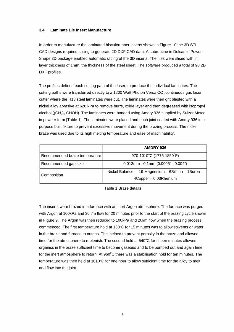
3.4 Laminate Die Insert Manufacture
In order to manufacture the laminated biscuit/runner inserts shown in Figure 10 the 3D STL
CAD designs required slicing to generate 2D DXF CAD data. A subroutine in Delcam’s Power-
Shape 3D package enabled automatic slicing of the 3D inserts. The files were sliced with in
layer thickness of 1mm, the thickness of the steel sheet. The software produced a total of 90 2D
DXF profiles.
The profiles defined each cutting path of the laser, to produce the individual laminates. The
cutting paths were transferred directly to a 1200 Watt Photon Versa CO2 continuous gas laser
cutter where the H13 steel laminates were cut. The laminates were then grit blasted with a
nickel alloy abrasive at 620 kPa to remove burrs, oxide layer and then degreased with isopropyl
alcohol ((CH3)2 CHOH). The laminates were bonded using Amdry 936 supplied by Sulzer Metco
in powder form [Table 1]. The laminates were placed and each joint coated with Amdry 936 in a
purpose built fixture to prevent excessive movement during the brazing process. The nickel
braze was used due to its high melting temperature and ease of machinability.
AMDRY 936
Recommended braze temperature 970-1010oC (1775-1850oF)
Recommended gap size 0.013mm - 0.1mm (0.0005” - 0.004”)
Composition Nickel Balance. – 19 Magnesium – 6Silicon – 1Boron –
4Copper – 0.03Rhenium
Table 1 Braze details
The inserts were brazed in a furnace with an inert Argon atmosphere. The furnace was purged
with Argon at 100kPa and 30 l/m flow for 20 minutes prior to the start of the brazing cycle shown
in Figure 9. The Argon was then reduced to 100kPa and 20l/m flow when the brazing process
commenced. The first temperature hold at 150oC for 15 minutes was to allow solvents or water
in the braze and furnace to outgas. This helped to prevent porosity in the braze and allowed
time for the atmosphere to replenish. The second hold at 540oC for fifteen minutes allowed
organics in the braze sufficient time to become gaseous and to be pumped out and again time
for the inert atmosphere to return. At 960oC there was a stabilisation hold for ten minutes. The
temperature was then held at 1010oC for one hour to allow sufficient time for the alloy to melt
and flow into the joint.

9
Figure 9 Heating and cooling profile of the brazing process
The inserts were allowed to cool in the furnace below the solids temperature of the braze at
approximately 960oC at which point they were removed from the furnace and air quenched.
Figure 10 shows the traditional insert after final machining of the exterior, runner and ejector
holes.
Figure 10 Insert after machining
0
100
200
300
400
500
600
700
800
900
1000
1100
0 20 40 60 80 100 120 140 160 180 200 220 240 260 280 300 320 340 360 380 400 420
Time (mins)
Tem
per
atu
re o
C
Furnace profile

10
3.5 Casting Procedure
The experiments involved a series of casting trials which were conducted at production speeds
to maintain a representative die temperature.
The cooling channels were tested to ensure no leaks were present. This was achieved by
simply blocking the outlet of the water channel, connecting the inlet to mains water (400 kPa)
and checking for leaks. No leaks were detected.
The casting was conducted on a Frech 125 DAK SDV cold chamber die-casting machine which
was modified to allow the solidification time to be reduced below 3 Seconds. This is not a
standard procedure due to the danger involved with opening a die whilst aluminium is potentially
molten. To safe guard against injury the area was sealed off and machine guards put in place.
The die casting machine cycle was set up as previously shown in Figure 8. The cycle time was
set at approximately 170 shots per hour (21 second cycle) with a solidification time of 3
seconds. The die was initially heated with a gas lance for 1½ hours and then 150 shots cast to
achieve the dies working temperature of 2000C – 2500C. Thereafter, samples were taken every
10 shots and the cooling time for each shot recorded. After every 10 shots the cooling time was
decreased by 0.1 of a seconds until there were signs of a biscuit burst.

11
4 RESULTS
4.1 Simulation Results
Thermal images show the rate at which solidification occurs in Figure 11 & Figure 12. Both the
traditionally cooled and conformally cooled thermal image shows the majority of the casting had
solidified after 2 seconds with the exception of the biscuit area. The centre of the traditionally
cooled biscuit takes approximately 10 seconds to fully solidify in comparison to 9 seconds for
the conformally cooled image.
Figure 11 Traditionally cooled solidification time

12
Figure 12 Conformal cooling solidification time
This is confirmed when comparing the raw data from thermocouple points 2,3 & 4 that were
situated in the biscuit and runner. Aluminium LM24 solidifies between 520oC and 580oC which is
where crystallisation begins and ends, this is termed latent heat of fusion shown in Figure 13.
Thermo couple 2 and 3 are located in the centre of the biscuit, solidification begins after 1
second and ends after approximately 8 seconds. Thermocouple 4 is located at the edge of the
runner near the die surface and is naturally is the first area to solidify, starting at 0.3 of a second
and finishing at approximately 5 seconds. Figure 13 shows there is no significant difference
between the traditionally cooled (TC) and conformally cooled (CC) insert solidification times.
Figure 13 Traditional cooling (TC) verses conformal cooling (CC) (thermocouples 2-4)
Thermocouples 5,6,7 & 8 were situate in the insert and as one would expect the closer to the
die surface the thermocouple was, the greater the temperature recorded. This can be see in
Figure 14 where traditionally cooled thermocouple 5 (TC5) is approximately 55oC hotter than
traditionally cooled thermocouple 8 (TC8) the same is true of conformally cooled thermocouple
5 and 8 (CC5 & CC8).
350
400
450
500
550
600
650
0 5 10 15 20 25
Time (s)
Tem
p (
oC
)
TC2 TC3 TC4 CC4 CC3 CC2
Liquid aluminium above 5800C
Latent heat of fusion
Solid aluminium, below 520oC

13
When comparing the traditional and conformal thermocouple points it can be seen that the
conformally cooled insert is typically 20oC cooler than that of the traditionally cooled insert for
each thermocouple location [Figure 14, TC7 and CC7 for example].
Figure 14 Traditional cooling (TC) verses conformal cooling (CC) (thermocouples 5-8)
4.2 Results From Casting
The results from both the traditional and conformal cooled tool inserts were the same. During
the casting trials the components were visually examined for signs of a burst biscuit. In both the
traditionally and conformally cooled inserts the solidification time could be reduced from 3.5
seconds down to 1 second before signs of a burst biscuit occurred. The lowest time before
failure of the biscuit and casting was 0.7 seconds. Failure was determined the biscuit being
semi molten and separating from the runner/casting during ejection.
100
120
140
160
180
200
220
240
260
280
0 2 4 6 8 10 12 14 16 18 20
Time (S)
Tem
p (
oC
)
TC5 CC5 TC6 CC6 TC7 CC7 TC8 CC8

14
5 DISCUSSION
The Magmasoft simulation does not show an improved solidification time of the casting using
the conformal cooled design, shown in Figure 13. The conformally cooled design however, is
approximately 20oC cooler than the traditionally cooled insert, shown in Figure 14.. The two
simulations show little difference in the cooling performance of the channel designs.
This was verified by the casting trials, proving that the simulation is accurate at predicting
solidification rates. It is clear that the design of a conformal cooling channel is critical since both
the simulation and physical casting experimentation showed no reduction in solidification time.
The casting trials however, showed a discrepancy in the simulated time for the biscuit to reach
solidification since the die could be opened at 1 second with no signs of a burst biscuit. The
simulated thermal images Figure 11& Figure 12 show the biscuit taking 9-10 seconds to reach
solidification. This could be due to insufficient or incorrectly placed theoretical thermocouples.
The casting trial show that the outermost surface of the biscuit formed a solidified aluminium
skin containing the remaining solidifying aluminium inside the it. This allowed the die to be
opened at 1 second. Below 0.7 seconds the skin fails creating a burst biscuit.
Although the conformal cooled channel had 1½ times the surface area and volume it evidently
was not enough to remove the heat.
15
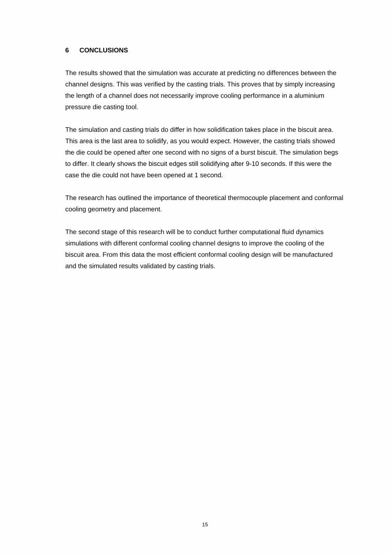
6 CONCLUSIONS
The results showed that the simulation was accurate at predicting no differences between the
channel designs. This was verified by the casting trials. This proves that by simply increasing
the length of a channel does not necessarily improve cooling performance in a aluminium
pressure die casting tool.
The simulation and casting trials do differ in how solidification takes place in the biscuit area.
This area is the last area to solidify, as you would expect. However, the casting trials showed
the die could be opened after one second with no signs of a burst biscuit. The simulation begs
to differ. It clearly shows the biscuit edges still solidifying after 9-10 seconds. If this were the
case the die could not have been opened at 1 second.
The research has outlined the importance of theoretical thermocouple placement and conformal
cooling geometry and placement.
The second stage of this research will be to conduct further computational fluid dynamics
simulations with different conformal cooling channel designs to improve the cooling of the
biscuit area. From this data the most efficient conformal cooling design will be manufactured
and the simulated results validated by casting trials.

16
ACKNOWLEDGEMENTS
The authors would like to thank the following for supporting this work:
Foresight Vehicle Programme
The Engineering and Physical Sciences Research Council (EPSRC)
Delcam International
Dyson Ltd
Kemlows Die Casting Products Ltd for their support and casting trials.
MAGMA for running the thermal the finite element simulations.
REFERENCES
1. Wayde R. Schmidt, Ronald D. White, Connie E. Bird, Joseph V. Bak, Conformal cooling vs.
conventional cooling: an injection moulding, case study with 3-dimensional printing. Solid
Freeform and Additive Fabrication, Materials Research Society Publications, Volume 625,
April 24-26, 2000, pages 51 – 56, ISBN: 1-55899-533-1
2. Dickens P.M. Rapid Prototyping – Past, Present & Future. Journal of The Institute of
Engineering Designers, January 1999, pages 12-15, ISSN 0013-7858
3. Xu-X, Sachs E., Allen S. The design of conformal cooling channels in injection moulding
tooling, Polymer Engineering and Science, Volume41, July 2001, pages 1265-1279
4. Halford B. Rapid Tooling, Journal of the Institute of Engineering Designers May 1999,
pages 4-6, ISSN 0013-7858
5. Obikawa T. Sheet Steel Lamination for Rapid Manufacturing, Journal of Materials
Processing Technology, Volume 89-90, 1999, pages 171-176
6. Xiaorong Xu, Emanuel Sachs, Samuel Allen, The design of conformal cooling channels in
injection mould tooling, Polymer and Engineering Science, July 2001, Volume 41, Number
7, pages 1265-1279