Analysis of a Nailed Soil Slope Using Limit Equilibrium and Finite Element Methods€¦ · ·...
23
Analysis of a Nailed Soil Slope Using Limit Equilibrium and Finite Element Methods S. Rawat 1 • A. K. Gupta 1 Received: 5 September 2016 / Accepted: 22 October 2016 / Published online: 28 October 2016 Ó Springer International Publishing Switzerland 2016 Abstract This paper aims at the two most common methods used for slope stability analysis. An attempt has been made to bring out the differences in results of rein- forced slope stability analysis obtained from SLOPE/W (limit equilibrium based) and PLAXIS 2D (finite element based). The analysis is carried out on two slope angles of 45° and 60°, which are reinforced with nails at three dif- ferent inclinations of 0°, 15° and 30° respectively. Both the slope angles and all nail inclinations are taken from the horizontal. A comparative study on stability parameters such as factor of safety, critical slip surfaces and nail forces has been carried out. The limit equilibrium method is found to yield higher values of factor of safety in comparison to finite element method. The failure surfaces from both methods are found to vary significantly. Large nail forces are observed by limit equilibrium method for 45° slope with all nail inclinations, whereas for 60° slope angle, finite element method shows an increase in the nail forces. The effect of other parameters like bond length in limit equi- librium, soil–nail interaction and bending stiffness in finite element are also studied. Keywords Limit equilibrium Finite element Factor of safety Slip surface Nail forces Introduction Soil nailing has emerged as an effective ground improve- ment technique especially in cases of slope instability. The unstable slopes can now be improved and made stable by the use of soil nailing technique. These reinforced slopes have to be analyzed for stability and their reinforcement methods. The stability analysis of reinforced slopes has been carried out by the traditional limit equilibrium approach by many researchers [1–4]. These limit equilib- rium methods also known as the ‘method of slices’ is based on the concept of dividing the failure mass into slices, with certain assumptions on the interslice force distribution, for calculating the factor of safety. The assumptions are usu- ally focused on inclination or location of the interslice forces and a pre-chosen slip surface of an assumed geometry like log-spiral, wedge and circular [5]. In addition to the limit equilibrium method (LEM), researchers have also employed the use of limit analysis which includes an upper bound approach and a lower bound approach. The lower bound approach [6, 7] incor- porates static permissible stress fields in the analysis, which are usually assumed and do not hold any significant rela- tions to the actual stress fields. Hence it is not easy to obtain the lower bound solutions for a practical slope problem. In the upper bound approach, the kinematically admissible velocity fields are constructed by a rigid ele- ment which makes the limit analysis of slope stability suitable for complex conditions such as slopes with com- plex geometries, profiles, groundwater conditions and complicated loadings [8–10]. However, rigid finite ele- ments, linear finite elements, non linear programming or special sequential quadratic programming algorithm has also been used to obtain the optimal upper bound solution for structures and geotechnical problems [11]. & A. K. Gupta [email protected] S. Rawat [email protected] 1 Department of Civil Engineering, Jaypee University of Information Technology, Waknaghat, Solan, Himachal Pradesh 173234, India 123 Int. J. of Geosynth. and Ground Eng. (2016) 2:34 DOI 10.1007/s40891-016-0076-0
Transcript of Analysis of a Nailed Soil Slope Using Limit Equilibrium and Finite Element Methods€¦ · ·...

Analysis of a Nailed Soil Slope Using Limit Equilibrium and FiniteElement Methods
S. Rawat1 • A. K. Gupta1
Received: 5 September 2016 / Accepted: 22 October 2016 / Published online: 28 October 2016
� Springer International Publishing Switzerland 2016
Abstract This paper aims at the two most common
methods used for slope stability analysis. An attempt has
been made to bring out the differences in results of rein-
forced slope stability analysis obtained from SLOPE/W
(limit equilibrium based) and PLAXIS 2D (finite element
based). The analysis is carried out on two slope angles of
45� and 60�, which are reinforced with nails at three dif-
ferent inclinations of 0�, 15� and 30� respectively. Both the
slope angles and all nail inclinations are taken from the
horizontal. A comparative study on stability parameters
such as factor of safety, critical slip surfaces and nail forces
has been carried out. The limit equilibrium method is found
to yield higher values of factor of safety in comparison to
finite element method. The failure surfaces from both
methods are found to vary significantly. Large nail forces
are observed by limit equilibrium method for 45� slope
with all nail inclinations, whereas for 60� slope angle, finiteelement method shows an increase in the nail forces. The
effect of other parameters like bond length in limit equi-
librium, soil–nail interaction and bending stiffness in finite
element are also studied.
Keywords Limit equilibrium � Finite element �Factor of safety � Slip surface � Nail forces
Introduction
Soil nailing has emerged as an effective ground improve-
ment technique especially in cases of slope instability. The
unstable slopes can now be improved and made stable by
the use of soil nailing technique. These reinforced slopes
have to be analyzed for stability and their reinforcement
methods. The stability analysis of reinforced slopes has
been carried out by the traditional limit equilibrium
approach by many researchers [1–4]. These limit equilib-
rium methods also known as the ‘method of slices’ is based
on the concept of dividing the failure mass into slices, with
certain assumptions on the interslice force distribution, for
calculating the factor of safety. The assumptions are usu-
ally focused on inclination or location of the interslice
forces and a pre-chosen slip surface of an assumed
geometry like log-spiral, wedge and circular [5].
In addition to the limit equilibrium method (LEM),
researchers have also employed the use of limit analysis
which includes an upper bound approach and a lower
bound approach. The lower bound approach [6, 7] incor-
porates static permissible stress fields in the analysis, which
are usually assumed and do not hold any significant rela-
tions to the actual stress fields. Hence it is not easy to
obtain the lower bound solutions for a practical slope
problem. In the upper bound approach, the kinematically
admissible velocity fields are constructed by a rigid ele-
ment which makes the limit analysis of slope stability
suitable for complex conditions such as slopes with com-
plex geometries, profiles, groundwater conditions and
complicated loadings [8–10]. However, rigid finite ele-
ments, linear finite elements, non linear programming or
special sequential quadratic programming algorithm has
also been used to obtain the optimal upper bound solution
for structures and geotechnical problems [11].
& A. K. Gupta
S. Rawat
1 Department of Civil Engineering, Jaypee University of
Information Technology, Waknaghat, Solan,
Himachal Pradesh 173234, India
123
Int. J. of Geosynth. and Ground Eng. (2016) 2:34
DOI 10.1007/s40891-016-0076-0

The finite element method (FEM) [12] is also used to
analyze the failure zone, soil non–linearity and the staged
construction effect to predict the actual site conditions [13].
Numerical modelling of reinforced slopes by finite element
method has proved very useful in prediction of slope
deformation, stress analysis [14], nail pullout resistance
[15, 16], nail forces along nail length, nail force variations
with cohesion, angle of friction and lateral movement of
slope [17–20]. The calculation of factor of safety using
finite element is also possible by using the strength
reduction method [21–23].
The strength reduction method (SRM) analysis is the
reduction of strength parameters (/ and c) by factor of
safety while the body forces due to weight of soil and
other external loads are applied until system cannot
maintain a stable condition [24]. This technique is also
adopted in several well-known commercial geotechnical
finite element or finite difference programs like PLAXIS
2D, SNAIL, ANSYS, FLAC 2D [25]. The strength
reduction approach has also been used to solve pseudo-
static stability problems in a frictional-cohesive material
[26]. Gurocak et al. [27] have applied strength reduction
method in rock slope stability analysis using two–di-
mensional (2D) finite element program. Although 2D
analysis provides valuable insight into the behaviour of
nailed slopes, the effect of soil–nail interaction is not
adequately considered.
Recently, other method like the artificial neural net-
works (ANN) has also been developed to study the
deformation of soil nailed walls [28]. The factor of safety
calculation is now carried by measuring the strains using
Fiber Bragg grating (FBG) sensing technology [29].
Esmaili [30] used close range photogrammetry for dis-
placement measurement of soil nail walls. The global
stability and sliding stability of soil nail walls against
ultimate limit states are also evaluated using reliability
analysis based on Monte Carlo simulation technique [31].
Reinforced slope stability analysis is also done by using
statistical methods, adaptive neuro fuzzy inference system
(ANFIS) and distinct element analysis method (DEM)
[32].
This paper is an attempt to bring out the possible dif-
ferences between the two most commonly used slope sta-
bility methods (LEM and FEM) in analysing the response
of soil nailed slopes using software packages SLOPE/W
and PLAXIS 2D v8.1. The numerical modelling of
experimental work carried out by Rawat and Gupta [18] on
nailed soil slope at different slope angles of 45� and 60�using nail inclinations of 0�, 15� and 30� with the hori-
zontal has been done. The comparison of factor of safety,
failure slip surfaces and nail forces from LEM and FEM
are studied and validated by the experimental results from
Rawat and Gupta [18].
Reinforced Slope Stability Analysis Using LimitEquilibrium Method
The response of reinforced systems is primarily governed
by the soil structure interaction. The interaction between
the soil which provides both mobilized and resisting
stresses and the structural members (nails) that helps in the
load transfer mechanism. General limit equilibrium
approach ensures static equilibrium of the system, thereby
providing a global factor of safety for the ultimate limit
state [5]. The factor of safety calculation as obtained by the
general limit equilibrium (GLE) or just limit equilibrium
(LE) method incorporates the use of interslice shear–nor-
mal forces and two types of factor of safety [33].
(a) Factor of safety with respect to moment equilibrium
(Fm)
Fm ¼P
ðc0bRþ N � ubð ÞR tan/0ÞP
Wx�P
Nf �P
Ddð1Þ
(b) Factor of safety with respect to force equilibrium
(Ff)
Ff ¼P
ðc0b cos aþ N � ubð Þ tan/0 cos aÞP
N sin a�P
D cosxð2Þ
The normal force at the base of each slice (N) is the
major variable in both equations of factor of safety. The
value of this normal force is dependent on the shear forces
(XL and XR) acting on the slices as shown in Fig. 1.
The base normal force is obtained by the relation:
N ¼W þ XR � XLð Þ � ðc0b sin aþ ub sin a tan ;0
FÞ
cos aþ sin a tan ;0F
ð3Þ
Fig. 1 Forces acting on an interslice
34 Page 2 of 23 Int. J. of Geosynth. and Ground Eng. (2016) 2:34
123

where, c0 and /0 = effective cohesion and effective angle
of friction u = pore water pressure W, D and N = slice
weight, concentrated point load and slice base normal force
a = slice base inclination with the horizontal b, f, d,
x = geometric parameters.
The normal force calculated from Eq. (3) is used in the
factor of safety calculation using Eqs. (1) and (2) for each
slice for a range of k values. The k value is the difference
between the specified function f(x) used to relate the nor-
mal—shear forces on the slices and applied function f(x)
used by the LEM software [34]. The expression to find the
relationship between the shear and normal forces on a slice
is also given by Morgenstern and Price in 1965 as:
X ¼ E � f xð Þ � k ð4Þ
where, X = interslice shear force E = interslice normal
force f(x) = interslice function (half–sine function default
SLOPE/W) k = percentage of function used.
The factor of safety using both the condition of moment
and force is calculated until convergence is reached
between the two FOS. The values are found to converge,
when the FOS plot for moment and force intersect for a
specific value of k. This constitutes the global factor of
safety as achieved by the LEM analysis of slopes.
The stability analysis in LEM is primarily an indeter-
ministic problem. So, inorder to change the problem to
statically deterministic solution, number of unknowns must
be equal to the number of equations. Various assumptions
such as no interslice forces (Fellinius method), no interslice
shear forces (Bishop’s method), only horizontal force
equilibrium of wedge (Janbu’s method) are accounted to
achieve a factor of safety for the slope failure. However an
additional complexity is introduced into the analysis with
the use of reinforcement to stabilize the slope. The rein-
forcement parameters are prescribed, which do not intro-
duce any unknowns in the analysis, but contributes
additional known reinforcement forces that are included in
the appropriate equilibrium equations [35]. The LEM
method utilizes the trial slip surface method, inorder to
locate the most optimum slip surface having the lowest
factor of safety. The slip surfaces considered in the LEM
can be circular, piece—wise linear or a combination of
curved and linear shapes. The procedure to find the most
critical slip surface is also affected by stratigraphic
boundaries of the slopes. To avoid unrealistic slip surface
and factor of safety, the LEM package offers an option of
defining the regions for occurrence of slip surface on the
ground surface and point of axis along which the moment
equilibrium is to be calculated. The present study uses the
software package SLOPE/W, to analyse the reinforced
slope by LEM.
Modelling and Analysis Using SLOPE/W
SLOPE/W is a sub-routine of the software package GEO-
SLOPE. In the present study, reinforced soil slope are
modelled with two different slope angles of 45� and 60�with horizontal respectively. These soil slopes are rein-
forced using nails at three different nail inclinations from
horizontal of 0�, 15� and 30� respectively [36]. SLOPE/W
package enables construction of the soil slopes by defining
its regions. The dimensions of the soil slope have been
adopted from the experimental work done on nailed soil
slopes [18]. The dimensions of the slope model used for
experimental studies are scaled down and incorporated in
SLOPE/W, by using a scale of 1 cm = 0.5 m.
The slope is modelled at different slope angles by (x,
y) coordinate system available in the package. Material of
the slope is assigned, once the slope regions have been
determined. The slopes are then reinforced with the help of
nails. SLOPE/W package provides the option of using
reinforcement in the form of anchor, geosynthetic, nail and
pile. For the present study reinforcement of slopes has been
done using nail element. A surcharge load is applied at the
top of slope, which is also scaled down from the experi-
mental values [18]. The entry and exit of slip surfaces at
the ground surface along with the slip surface axis and
limits are also applied at the model. The simulated model
used in the analysis is shown in Fig. 2. Amidst of all other
methods available in the limit equilibrium package, the
analysis is carried out by Morgenstern–Price method which
uses a relation between interslice shear forces and inters
slice normal forces. The interslice function selected in the
analysis is a half–sine function with a constant factor of
safety distribution calculation. The soil and nail properties
used in the model are summarized in Table 1.
The nails used in reinforcing of the slopes are simulated
without a facing in the form of ‘no anchorage’ of nails at
the slope face. The nail forces are treated as distributed
forces over the nail length and the overall global factor of
safety (F of S dependent) is included in the analysis. The
reinforcement in SLOPE/W is treated as concentrated loads
which reduces the destabilizing forces. The equilibrium
equations used in the analysis are based on the shear
mobilized at the base of each slice and at the reinforce-
ment. The mobilized shear (Sm) is calculated using the
Eq. (5), based on an assumption that the shear resistance of
soil and reinforcement are developed at the same rate [5].
Sm ¼ Ssoil
F of Sþ Sreinforcement
F of Sð5Þ
The soil nails used in the analysis are stiffer than the
soil. Hence the reinforcement forces are limited by the
Int. J. of Geosynth. and Ground Eng. (2016) 2:34 Page 3 of 23 34
123

allowable loads in the reinforcement. Instead of dividing
the shear resistance of reinforcements with global factor of
safety, reduction factors are used to restrict the mobilized
reinforcements. This option is available by not considering
the F of S dependency for the analysis.
SLOPE/W Results from Limit EquilibriumAnalysis
Factor of Safety from SLOPE/W
From Table 2, it is observed that the factor of safety cal-
culated from the limit equilibrium method is found to be
1.82 for a slope of 45� with nail inclination of 15�. Simi-
larly for a slope of 60�, the highest factor of safety of 1.53
is found for nail inclination of 15�. The factor of safety as
can be observed from Table 2 is found to increase from
nail inclination of 0� to 15� and then decrease from 15� to30�. This pattern is observed for both the slope angle of 45�and 60�. The Morgenstern–Price method employed by
SLOPE/W utilizes a k value to check for the convergence
of the results. As shown in Fig. 3a, b, the FOS values
attained for nail inclinations of 15� in 45� and 60� slopes
are found to satisfy the convergence of results. The FOS as
obtained is the intersection of FOS from moment equilib-
rium (Fm) and FOS from force equilibrium (Ff).
Failure Slip Surface from SLOPE/W
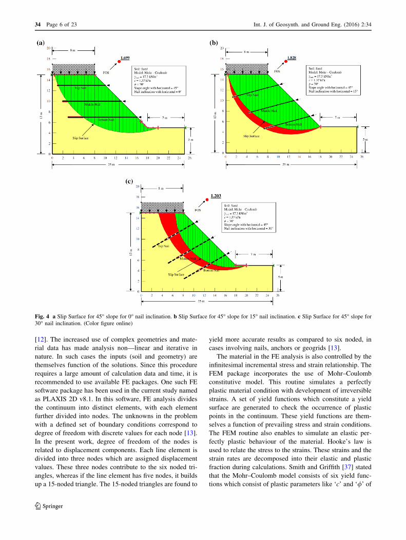
From the Fig. 4a, b and c, it can be seen that a circular slip
surface is generated for reinforced slopes of 45�. It is alsoobserved from the figures that the slip surface is passing
through the entire crest in cases with nail inclination of 0�and 15�. However, with nail inclination of 30�, a much
smaller slip surface is observed. The red shaded portion of
the slip surface indicates the band of trial slip surfaces with
the same factor of safety.
Fig. 2 Modelling of soil slope
in SLOPE/W
Table 1 Summary of material used in modelling from Rawat and
Gupta [18]
Parameters Values
Soil Well graded sand (SW)
Bulk unit weight of soil (cbulk) 17.3 kN/m3
Cohesion (c) 1.37 kN/m2
Angle of friction (/�) 30�Surcharge load 0.294 kN/m3
Pull-out resistance of nails 100 kN/m2
Tensile capacity of nails 200 kN
Nail spacing (s) 2 m
Length of nail (l) 7.5 m
Table 2 Factor of safety from limit equilibrium method (SLOPE/W)
Slope angles with
horizontal (�)Factor of safety
Nail inclinations with horizontal
0� 15� 30�
45 1.69 1.82 1.20
60 1.50 1.53 1.10
34 Page 4 of 23 Int. J. of Geosynth. and Ground Eng. (2016) 2:34
123

For the 60� slope, it can be seen from the Fig. 5a, b, c
that the slip surface is circular in shape. For slopes with
nail inclination of 0� and 15�, the variation in the factor of
safety for the trial surface is small. This is indicated by thin
red shaded portion of the slip surface. However, 60� slopereinforced with 30� nail inclination is found to have a small
slip failure and critical slip surface is found to lie close to
the slope face.
Nail Axial Forces from SLOPE/W
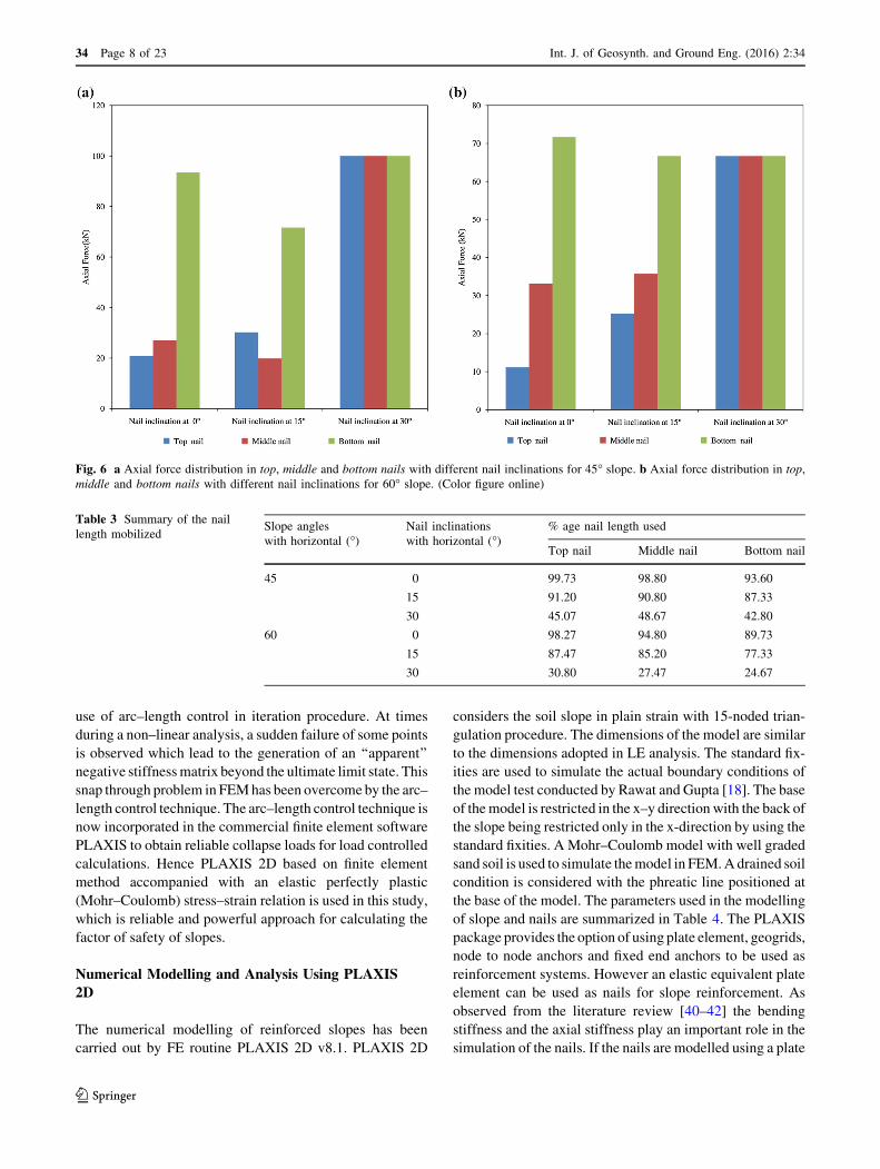
From the Fig. 6a, b, it is observed that the bottom nail with
0�, 15� and 30� is found to bear the maximum nail axial
forces for both 45� and 60� slopes. For nail inclinations of0� and 15�, the axial forces are found to increase from top
nail to middle nail and maximum for the bottom nails.
However, for 30� inclined nail 45� slope, an axial force of
100 kN is found in the top, middle and bottom nails.
Similarly, an axial force of 66.66 kN is found for top,
middle and bottom nails in 60� slope with 30� nail incli-
nation. The maximum axial force of 100 kN is found to be
in the bottom nail for 45� slope with nail inclination at 30�.In 60� slope, the bottom nail with nail inclination of 0� isfound to bear the maximum axial nail force of 71.67 kN.
Effect of Bond Length from SLOPE/W
From the analysis carried out in SLOPE/W, it is found that
the length of nails modelled and mobilized during slip
failure vary with the nail inclination and location. The nails
at all the inclinations of 0�, 15� and 30� are initially
modelled with a constant length of 7 m converted to scale.
The SLOPE/W analysis yields that the nail inclination of
30� in both the slope angles, enables less than 50% of nail
length mobilization to resist slope failure. For the other two
nail inclinations 0� and 15�, it is found that more than 90%
of the nail length has been used to resist the shearing
action. It is found that if the failure surface uses maximum
nail length, the reinforcing action of the nails is completely
mobilized. The summary of the percentage mobilized nail
length is given in Table 3. The LE analysis of the rein-
forced slope also accounts for the fact that load transfer
mechanism of nails is governed by pull–out resistance or
tensile capacity of nails. It is visible from Fig. 4a, b, that
45� slope with 0� and 15� nail inclinations do not depict
any nail breakage. This signifies that the load transfer
mechanism is governed by nail pullout capacity.
For 30� nail inclination on 45� slope, nails are found to
break denoted by dashed lines (Fig. 7). This also stands for
the fact that nail has completely utilized its pullout capacity
and is now transferring the load by its tensile capacity. A
similar pattern of nail load transfer mechanism is observed
in 60� reinforced slope with 30� nail inclination as shown
in Fig. 8.
Reinforced Slope Stability Analysis Using FiniteElement Method
With the advantage of no assumption for location of failure
surface and interslice forces, finite element (FE) method
has been widely accepted for the analysis of slope stability
Fig. 3 a FOS versus k for 45� slope with nail inclination of 15�. b FOS versus k for 60� slope with nail inclination of 15�
Int. J. of Geosynth. and Ground Eng. (2016) 2:34 Page 5 of 23 34
123
[12]. The increased use of complex geometries and mate-
rial data has made analysis non—linear and iterative in
nature. In such cases the inputs (soil and geometry) are
themselves function of the solutions. Since this procedure
requires a large amount of calculation data and time, it is
recommended to use available FE packages. One such FE
software package has been used in the current study named
as PLAXIS 2D v8.1. In this software, FE analysis divides
the continuum into distinct elements, with each element
further divided into nodes. The unknowns in the problem
with a defined set of boundary conditions correspond to
degree of freedom with discrete values for each node [13].
In the present work, degree of freedom of the nodes is
related to displacement components. Each line element is
divided into three nodes which are assigned displacement
values. These three nodes contribute to the six noded tri-
angles, whereas if the line element has five nodes, it builds
up a 15-noded triangle. The 15-noded triangles are found to
yield more accurate results as compared to six noded, in
cases involving nails, anchors or geogrids [13].
The material in the FE analysis is also controlled by the
infinitesimal incremental stress and strain relationship. The
FEM package incorporates the use of Mohr–Coulomb
constitutive model. This routine simulates a perfectly
plastic material condition with development of irreversible
strains. A set of yield functions which constitute a yield
surface are generated to check the occurrence of plastic
points in the continuum. These yield functions are them-
selves a function of prevailing stress and strain conditions.
The FEM routine also enables to simulate an elastic per-
fectly plastic behaviour of the material. Hooke’s law is
used to relate the stress to the strains. These strains and the
strain rates are decomposed into their elastic and plastic
fraction during calculations. Smith and Griffith [37] stated
that the Mohr–Coulomb model consists of six yield func-
tions which consist of plastic parameters like ‘c’ and ‘/’ of
Fig. 4 a Slip Surface for 45� slope for 0� nail inclination. b Slip Surface for 45� slope for 15� nail inclination. c Slip Surface for 45� slope for30� nail inclination. (Color figure online)
34 Page 6 of 23 Int. J. of Geosynth. and Ground Eng. (2016) 2:34
123

the soil. Using these concepts for material transition, a
material stiffness matrix is developed by the FE analysis to
calculate the stiffness of each element and ultimately of the
entire volume of soil.
From the literature review, it has also been observed that
researchers [38, 39] employed the strength reduction
method of FE to obtain the factor of safety for slopes. In
strength reduction analysis, the convergence criterion is the
most critical factor for the assessment of factor of safety.
The strength reduction method also known as /–c reduc-
tion method is carried out by performing load advancement
number of steps. The reduction in the strength parameters
in carried out by using an incremental multiplier Msf. The
factor of safety is calculated by the expression:
SF ¼ Available strength
strength at failure¼ value of
XMsf at failure:
ð6Þ
The precision of the factor safety is a function of type of
constitutive soil model selected, type and size of the element,
discretized mesh, node location for displacement curve and
tolerance allowed for non-linear analysis. Depending on the
choice of the FE routine used, the model is found to have
reached the ultimate state if either the maximum number of
iteration is reached or the model has undergone a continuous
failuremechanismor the selected points in the continuumare
subjected to sudden change in the displacement. Inorder to
simulate the failure correctly FEMpackages also provide the
Fig. 5 a Slip Surface for 60� slope for 0� nail inclination. b Slip Surface for 60� slope for 15� nail inclination. c Slip Surface for 60� slope for30� nail inclination. (Color figure online)
Int. J. of Geosynth. and Ground Eng. (2016) 2:34 Page 7 of 23 34
123
use of arc–length control in iteration procedure. At times
during a non–linear analysis, a sudden failure of some points
is observed which lead to the generation of an ‘‘apparent’’
negative stiffnessmatrix beyond the ultimate limit state. This
snap through problem in FEMhas been overcome by the arc–
length control technique. The arc–length control technique is
now incorporated in the commercial finite element software
PLAXIS to obtain reliable collapse loads for load controlled
calculations. Hence PLAXIS 2D based on finite element
method accompanied with an elastic perfectly plastic
(Mohr–Coulomb) stress–strain relation is used in this study,
which is reliable and powerful approach for calculating the
factor of safety of slopes.
Numerical Modelling and Analysis Using PLAXIS
2D
The numerical modelling of reinforced slopes has been
carried out by FE routine PLAXIS 2D v8.1. PLAXIS 2D
considers the soil slope in plain strain with 15-noded trian-
gulation procedure. The dimensions of the model are similar
to the dimensions adopted in LE analysis. The standard fix-
ities are used to simulate the actual boundary conditions of
the model test conducted by Rawat and Gupta [18]. The base
of themodel is restricted in the x–y direction with the back of
the slope being restricted only in the x-direction by using the
standard fixities. A Mohr–Coulomb model with well graded
sand soil is used to simulate themodel in FEM.Adrained soil
condition is considered with the phreatic line positioned at
the base of the model. The parameters used in the modelling
of slope and nails are summarized in Table 4. The PLAXIS
package provides the option of using plate element, geogrids,
node to node anchors and fixed end anchors to be used as
reinforcement systems. However an elastic equivalent plate
element can be used as nails for slope reinforcement. As
observed from the literature review [40–42] the bending
stiffness and the axial stiffness play an important role in the
simulation of the nails. If the nails are modelled using a plate
Fig. 6 a Axial force distribution in top, middle and bottom nails with different nail inclinations for 45� slope. b Axial force distribution in top,
middle and bottom nails with different nail inclinations for 60� slope. (Color figure online)
Table 3 Summary of the nail
length mobilizedSlope angles
with horizontal (�)Nail inclinations
with horizontal (�)% age nail length used
Top nail Middle nail Bottom nail
45 0 99.73 98.80 93.60
15 91.20 90.80 87.33
30 45.07 48.67 42.80
60 0 98.27 94.80 89.73
15 87.47 85.20 77.33
30 30.80 27.47 24.67
34 Page 8 of 23 Int. J. of Geosynth. and Ground Eng. (2016) 2:34
123

element of circular cross section, then an equivalent flexural
rigidity and equivalent axial stiffness has to be calculated for
correct simulation of the soil nails. The formulation for
attaining the equivalent modulus of elasticity for the mod-
elled nails is given by Babu et al. [43]:
Eeq ¼ En
Anail
Aþ Eg
Agrout
Að7Þ
Similarly Equivalent axial stiffness is given by
Fig. 7 Slope stability by tensile
capacity of nails in 45� slopewith 30� nail inclination. (Colorfigure online)
Fig. 8 Slope stability by tensile
capacity of nails in 60� slopewith 30� nail inclination. (Colorfigure online)
Int. J. of Geosynth. and Ground Eng. (2016) 2:34 Page 9 of 23 34
123

EA ¼ En
Sh
P4d2n ð8Þ
The equivalent bending stiffness is calculated by the
relation:
EI ¼ En
Sh
P64
d4n ð9Þ
The equivalent plate diameter of the nail is calculated by
the PLAXIS software using the formulation:
deq ¼
ffiffiffiffiffiffiffiffiffiffiffiffiffiffiffiffiffiffi
12EI
EA
� �s
ð10Þ
The Eqs. (7), (8), (9) and (10) are used in the present
study to calculate the nail input values used for the analysis
as shown in Table 5.
To ensure proper soil–nail interaction, an interface of
virtual thickness factor (d) of 0.1 is used. This virtual
thickness factor is multiplied by the element thickness in
the procedure of mesh generation. The interface is assigned
the same material data set as done for the model. For
simulation of pullout resistance in the soil nails, an inter-
face strength reduction factor (Rinter) is used with a value of
2/3 in the absence of data from experimentation [13]. It
relates the strength of the soil to the strength of interface as
tan/interface
tan/soil
¼ Rinter andcinterface
csoil¼ Rinter ð11Þ
Once the soil nail interactions are modelled, a 2D mesh
is generated after the initial stresses are computed by the K0
procedure based on Janbu’s relation, K0 ¼ 1� sin/ð Þ. Afiner 2D mesh is generated at the interfaces of soil–nail for
achieving accurate results. No overconsolidation and pre-
overburden pressure are considered in the present analysis.
The simulated model is analysed by using the /–c reduc-
tion method (SRM). This calculation method yields a value
of incremental multiplierP
Msf as results converge when
slope failure is reached. This value of the incremental
multiplier is treated as FOS for the reinforced slope failure.
The complete modelled reinforced soil slope is shown in
the Fig. 9.
PLAXIS 2D Results from Finite Element Method
Factor of Safety from PLAXIS 2D
The PLAXIS 2D shows that 45� slope reinforced with nail
inclination of 15�, yields the maximum factor of safety of
1.43. For all the other inclinations of 0� and 30�, the factorof safety is found to be 1.36 and 1.15 respectively. As it
can be seen from Fig. 10, for 15� nail inclination the factor
of safety is increasing with slope displacement under sur-
charge |is achieved for a total displacement (|U|) of
0.462 m of slope. It can also be observed from Figs. 10 and
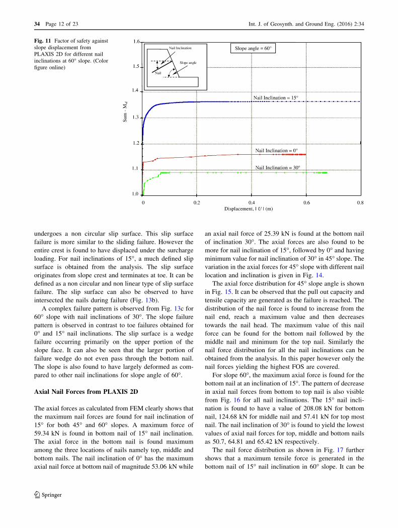
11 that 30� nail inclination in both 45� and 60� slope givesthe minimum factor of safety of 1.15 and 1.08 respectively.
Figure 10 also suggests that nail inclinations with mini-
mum factor of safety fail at a relative smaller displacement
as compared to the nail inclinations giving the maximum
FOS. The nail inclination of 0� corresponds to an inter-
mediate factor of safety value 1.36 for 45� slope and 1.17
for 60� slope respectively. Another important aspect that
can be brought to light is that for 60� slope, the factor of
safety increasing rapidly at small displacement of\0.1 m
and then remains constant until failure as the slope
Table 4 Material properties
used in numerical modelling
from Rawat and Gupta [18]
Properties Stiffness Alternate stiffness Strength
Simulated model Plain strain Eref 50,000 kN/m2 Gref 115,400 kN/m2 cref 1.37 kN/m2
Elements 15-node t 0.3 Eoed 403,800 kN/m2 / 30�Model type Mohr–Coulomb w 0�Material type Drained
cunsat 13.6 kN/m3
csat 19.68 kN/m3
Ko 0.5
Table 5 Properties of the
simulated nails used in
numerical modelling
Parameters Values Units Interface strength
Nail element and nail type Plate and elastic – Rinter 2/3
Axial stiffness (EA) 2.98 9 106 kN/m dinter 0.1
Flexural rigidity (EI) 113.64 9 103 kN m2/m
Diameter of nail (deq) 12 mm
Poisson’s ratio (t) 0.35 –
34 Page 10 of 23 Int. J. of Geosynth. and Ground Eng. (2016) 2:34
123

displacement increases. The maximum factor of safety for
60� is 1.37 achieved for 15� nail inclination. Similar to 45�slope, 0� and 30� show much lower values of factor of
safety. Nail inclination of 30� is found to have the mini-
mum factor of safety for 60� slope which is concurrent to
slope angle of 45�.
Slip Surface from PLAXIS 2D
From the analysis of reinforced slopes by FEM routine
PLAXIS, it is observed that different slopes with varying
nail inclination undergo non-circular slip surface failure.
Although these slip surfaces are found to vary with change
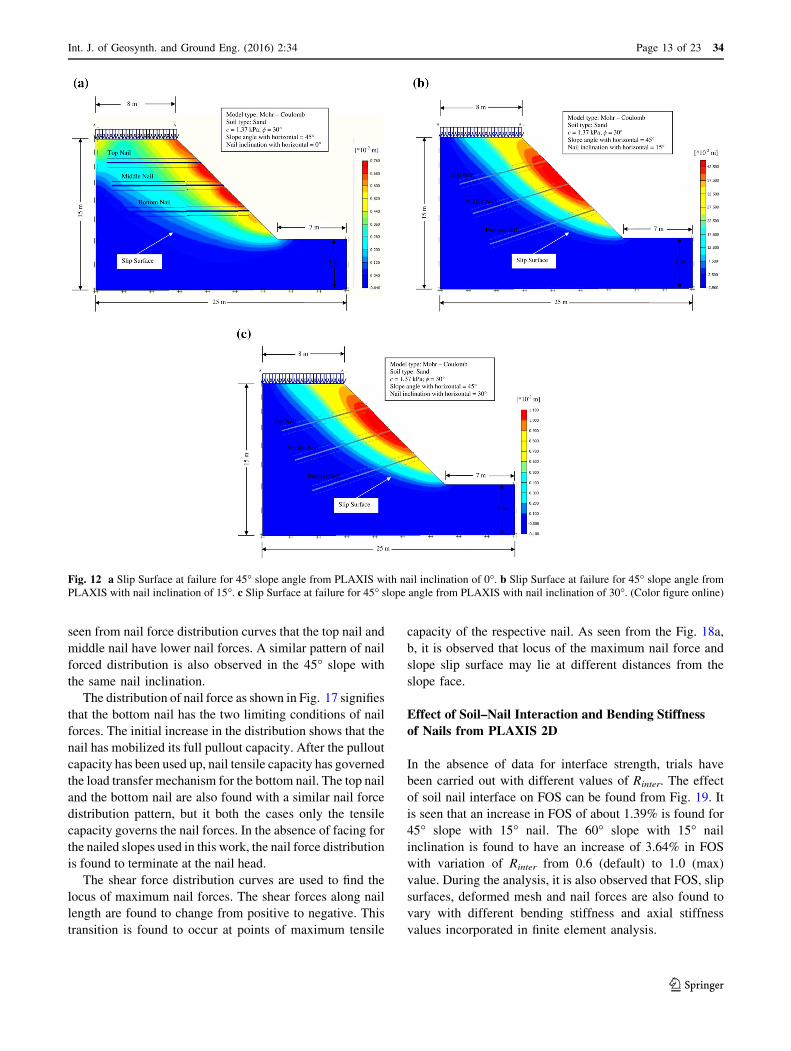
in nail inclination. Figure 12a depicts that FEM analysis
gives a slip surface passing in close proximity to the slope
face in case of nail inclined at 0� for 45� slope. A similar
pattern of non circular slip surfaces is attained from failure
of 45� slope with 15� and 30� nail inclinations. It can also
be observed from Fig. 12b, c that unlike 0� nail inclination,slip surfaces pass through the nails with 15� and 30� nail
inclinations. However in all three nail inclinations, the
maximum horizontal displacement is found to be near the
reinforced slope face.
The failure of 60� slope shows a different failure patternin comparison to 45� slopes. As observed from Fig. 13a, it
can be seen that for 0� nail inclination in 60� slope
Fig. 9 Numerical modelling of
reinforced soil slope in PLAXIS
2D
Fig. 10 Factor of safety against
slope displacement from
PLAXIS 2D for different nail
inclinations at 45� slope. (Colorfigure online)
Int. J. of Geosynth. and Ground Eng. (2016) 2:34 Page 11 of 23 34
123
undergoes a non circular slip surface. This slip surface
failure is more similar to the sliding failure. However the
entire crest is found to have displaced under the surcharge
loading. For nail inclinations of 15�, a much defined slip
surface is obtained from the analysis. The slip surface
originates from slope crest and terminates at toe. It can be
defined as a non circular and non linear type of slip surface
failure. The slip surface can also be observed to have
intersected the nails during failure (Fig. 13b).
A complex failure pattern is observed from Fig. 13c for
60� slope with nail inclinations of 30�. The slope failure
pattern is observed in contrast to toe failures obtained for
0� and 15� nail inclinations. The slip surface is a wedge
failure occurring primarily on the upper portion of the
slope face. It can also be seen that the larger portion of
failure wedge do not even pass through the bottom nail.
The slope is also found to have largely deformed as com-
pared to other nail inclinations for slope angle of 60�.
Axial Nail Forces from PLAXIS 2D
The axial forces as calculated from FEM clearly shows that
the maximum nail forces are found for nail inclination of
15� for both 45� and 60� slopes. A maximum force of
59.34 kN is found in bottom nail of 15� nail inclination.
The axial force in the bottom nail is found maximum
among the three locations of nails namely top, middle and
bottom nails. The nail inclination of 0� has the maximum
axial nail force at bottom nail of magnitude 53.06 kN while
an axial nail force of 25.39 kN is found at the bottom nail
of inclination 30�. The axial forces are also found to be
more for nail inclination of 15�, followed by 0� and having
minimum value for nail inclination of 30� in 45� slope. Thevariation in the axial forces for 45� slope with different naillocation and inclination is given in Fig. 14.
The axial force distribution for 45� slope angle is shownin Fig. 15. It can be observed that the pull out capacity and
tensile capacity are generated as the failure is reached. The
distribution of the nail force is found to increase from the
nail end, reach a maximum value and then decreases
towards the nail head. The maximum value of this nail
force can be found for the bottom nail followed by the
middle nail and minimum for the top nail. Similarly the
nail force distribution for all the nail inclinations can be
obtained from the analysis. In this paper however only the
nail forces yielding the highest FOS are covered.
For slope 60�, the maximum axial force is found for the
bottom nail at an inclination of 15�. The pattern of decreasein axial nail forces from bottom to top nail is also visible
from Fig. 16 for all nail inclinations. The 15� nail incli-
nation is found to have a value of 208.08 kN for bottom
nail, 124.68 kN for middle nail and 57.41 kN for top most
nail. The nail inclination of 30� is found to yield the lowest
values of axial nail forces for top, middle and bottom nails
as 50.7, 64.81 and 65.42 kN respectively.
The nail force distribution as shown in Fig. 17 further
shows that a maximum tensile force is generated in the
bottom nail of 15� nail inclination in 60� slope. It can be
Fig. 11 Factor of safety against
slope displacement from
PLAXIS 2D for different nail
inclinations at 60� slope. (Colorfigure online)
34 Page 12 of 23 Int. J. of Geosynth. and Ground Eng. (2016) 2:34
123
seen from nail force distribution curves that the top nail and
middle nail have lower nail forces. A similar pattern of nail
forced distribution is also observed in the 45� slope with
the same nail inclination.
The distribution of nail force as shown in Fig. 17 signifies
that the bottom nail has the two limiting conditions of nail
forces. The initial increase in the distribution shows that the
nail has mobilized its full pullout capacity. After the pullout
capacity has been used up, nail tensile capacity has governed
the load transfer mechanism for the bottom nail. The top nail
and the bottom nail are also found with a similar nail force
distribution pattern, but it both the cases only the tensile
capacity governs the nail forces. In the absence of facing for
the nailed slopes used in this work, the nail force distribution
is found to terminate at the nail head.
The shear force distribution curves are used to find the
locus of maximum nail forces. The shear forces along nail
length are found to change from positive to negative. This
transition is found to occur at points of maximum tensile
capacity of the respective nail. As seen from the Fig. 18a,
b, it is observed that locus of the maximum nail force and
slope slip surface may lie at different distances from the
slope face.
Effect of Soil–Nail Interaction and Bending Stiffness
of Nails from PLAXIS 2D
In the absence of data for interface strength, trials have
been carried out with different values of Rinter. The effect
of soil nail interface on FOS can be found from Fig. 19. It
is seen that an increase in FOS of about 1.39% is found for
45� slope with 15� nail. The 60� slope with 15� nail
inclination is found to have an increase of 3.64% in FOS
with variation of Rinter from 0.6 (default) to 1.0 (max)
value. During the analysis, it is also observed that FOS, slip
surfaces, deformed mesh and nail forces are also found to
vary with different bending stiffness and axial stiffness
values incorporated in finite element analysis.
Fig. 12 a Slip Surface at failure for 45� slope angle from PLAXIS with nail inclination of 0�. b Slip Surface at failure for 45� slope angle fromPLAXIS with nail inclination of 15�. c Slip Surface at failure for 45� slope angle from PLAXIS with nail inclination of 30�. (Color figure online)
Int. J. of Geosynth. and Ground Eng. (2016) 2:34 Page 13 of 23 34
123

Validation of Failure Surfaces
A model testing and experimental validation has been
incorporated for the present analysis. The laboratory model
testing carried out on soil nailed slope by Rawat and Gupta
[18] is used to validate the results as observed from LEM
and FEM analysis in this paper. It can be observed from
Fig. 20a, b, that the failure surface captured from LEM
analysis (SLOPE/W) and FEM analysis (PLAXIS 2D) are
comparable to the failure slip surface obtained from model
testing with slight variations. The slip surface found from
model testing is not necessarily a circular slip surface but a
non–circular slip surface or a log spiral surface. The
experimental results yield a shallow slip surface which is
concentrated near the slope face. The slip surface is found
to originate at the slope crest near the slope face. It prop-
agates towards the toe. For reinforced slope of 45�, the slipsurface intersects the slope face above the toe which can be
categorized as a slope failure. Moreover, a much visible toe
failure is found to occur for 60� reinforced slope. The
numerical modelling of this slope with LEM sub-routine
SLOPE/W shows a rather circular slip surface at failure.
Also it can be seen from Fig. 4a, b, c, that a deep failure
surface is predicted by limit equilibrium analysis which is
not the case from model testing. The slip surface by LEM
is also found to pass well below the slope toe for 45�reinforced slope, whereas a slope failure is obtained from
model testing. In case of 60� reinforced slope, both model
testing and LEM analysis depicts toe failure with variation
in slip surface depth. As mentioned earlier, LEM gives a
deep slip surface which originates away from slope face
and from the rear of slope crest, whereas the slip surface
from model testing is also circular but slightly steeper as
compared to LE analysis result. It can also be observed that
the experimental slip surface starts somewhere from the
crest and ends at the toe similar to LEM.
The slip surfaces obtained from PLAXIS 2D (FEM)
analysis are found to give results which are in good
Fig. 13 a Slip Surface at failure for 60� slope angle from PLAXIS with nail inclination of 0�. b Slip Surface at failure for 60� slope angle fromPLAXIS with nail inclination of 15�. c Slip Surface at failure for 60� slope angle from PLAXIS with nail inclination of 30�. (Color figure online)
34 Page 14 of 23 Int. J. of Geosynth. and Ground Eng. (2016) 2:34
123

agreement with model testing slip surfaces. For 45� rein-
forced slope, non–circular slip surface originating from
slope crest slightly away from slope face is observed from
both FEM analysis as well as experimentally. However,
PLAXIS also gives a base failure in contrast to slope
failure found by testing. From Figs. 12a to 13c, it can also
be seen that the stresses are found to be concentrated near
the slope face and decreases as distance from the slope face
increases. The slip surface for 60� reinforced slope
obtained from FEM is similar to the experimental slip
surface. Both slip surfaces are toe slope failure with non–
circular shape of slip and lie close to the slope face.
Hence it can be said that FE analysis carried out by
PLAXIS 2D gives more realistic failure surfaces as com-
pared to LE analysis by SLOPE/W. However, both the
analytical methods failed to predict the significant crest
Fig. 14 Axial nail forces at
different nail inclinations and
locations for 45� slope. (Colorfigure online)
Fig. 15 Nail force distribution
from PLAXIS 2D
Int. J. of Geosynth. and Ground Eng. (2016) 2:34 Page 15 of 23 34
123

settlement which occurred in model testing. The variations
between experimental work of Rawat and Gupta [18] and
the current analytical methods can be accounted for the
following reasons:
(a) LEM works on the concept of assumed failure
surface (circular in this case) with lowest factor of
safety in contrast to FEM where critical slip surface
is generated by failure stress–strains on the displace-
ment nodes. This makes FEM results more realistic
than LEM results.
(b) The boundary conditions modeled in LEM and FEM
are different from model testing. SLOPE/W does not
Fig. 16 Axial nail forces at
different nail inclinations and
locations for 60� slope. (Colorfigure online)
Fig. 17 Nail force distribution
from PLAXIS 2D
34 Page 16 of 23 Int. J. of Geosynth. and Ground Eng. (2016) 2:34
123

incorporate tools for boundary condition simulation
whereas in PLAXIS 2D the bottom boundary is fixed
in x–y direction, left and right model boundaries are
fixed in x–direction for all cases of reinforced slopes.
(c) The model testing is effected by settlement and
lateral displacement in all x, y and z directions,
which is not taken care of when simulated in either
LE or FE analysis as both are 2D analysis codes. The
slope and crest displacements observed in model
testing are significantly different from LEM and
FEM displacements of slope and crest, thus a
variation in slip surface generation also exists.
Comparison of Results from LEM and FEM
Comparison of Factor of Safety for Reinforced
Slopes
As observed from Table 6, it can be seen that limit equi-
librium method calculates a higher factor of safety as
compared to the finite element method. The LEM utilizes
the equilibrium of forces among the slices which requires
assumptions and compromises on the accuracy of the
method. The FOS given by the FEM analysis is on the
lower side. The FEM is based on the displacement of nodes
Fig. 18 a Shear force
distribution of 15� nailinclination for 45� slope.b Shear force distribution of 15�nail inclination for 60� slope
Int. J. of Geosynth. and Ground Eng. (2016) 2:34 Page 17 of 23 34
123

till the occurrence of slope failure. However, FOS as
obtained from both the analysis show a similar pattern with
the maximum FOS for nail inclination of 15� in both 45�and 60� slope. This is followed by the FOS for 0� nail
inclination. The minimum FOS of safety from LEM and
FEM is obtained for slope with nail inclination of 30�. Thepercentage increase in FOS with respect to FOS from FE
analysis is about 24.26% with nails inclined at 0� with
horizontal. For 15� nail inclination, LE analysis predicts
27.27% higher FOS as compared to FE analysis. For 30�nail inclination, this increase is significantly small which
comes out be 4.34%. All the above mentioned percentage
changes are for 45� slope angle. In case of 60� slope angle,this percentage variation in FOS between LEM and FEM
ranges from 1 to 28%. For nails inclination of 0�, a sig-
nificant percentage increase of 28.20% is observed, which
falls to 11.68% for 15� nail inclination. An increase in FOS
of just 1.85% is found with nail inclination 30� from both
analyses. The reasons for this higher FOS from LEM more
as compared to FOS from FEM can be:
(a) LE and FE analyses have fundamental difference in
the basic principles. The first is based on the limit
equilibrium formulations, which are dependent on
static force or moment equilibrium. As in Morgen-
stern–Price model used in LEM, a half–sine inter-
slice function is used to relate the interslice normal–
shear forces. This in turn is used to find slice base
normal force which gives the factor of safety with
respect to force and moment equilibrium. The
variation in FOS is obvious, since interslice weight
and slice base force will depend on the shape of
assumed slip surface which is circular in case of
LEM. Whereas FEM is based on a stress-strain
relationship, which can effectively accommodate the
change in stresses. The FE analysis in PLAXIS, for
example finds the slip surface, where the excessive
strains are localised, and computes the FOS by
strength reduction procedure for Mohr–Coulomb soil
model.
(b) The FOS is primarily related to the normal stress
distribution along the slip surface. A significant
difference in normal stress distribution, particularly
in the toe area, can be found between FE and LE
analyses for a particular slip surface [44]. This
difference in normal stress distribution results from
the shear stress concentrations, which are not,
captured in the LE analyses. In LEM, the normal
forces at the base are primarily derived from the
weight of the sliding mass and not the shear stress
distribution which results in higher FOS prediction.
(c) In this study also, no similarity in the interslice force
and critical shear surface was found between the
analyses in LE and FE methods. Both analysis
utilizes different shear forces and on different critical
surfaces. The FE analysis computes factor of safety
for each element along the slip surface, whereas a
single, weighted average FOS is computed in the LE
analyses. This leads to over prediction of FOS in
LEM.
Moreover, Krahn [44] states, ‘‘FE analyses can handle
variations in FOS without any difficulty of convergence,
due to stress redistributions for change in loading condi-
tions’’. However the convergence of simulations in LE is
found problematic for steep slip surfaces, whereas FE
overcomes such difficulties. This is why the computed FOS
from the FE analysis is regarded as more reliable.
Fig. 19 FOS variation with
Rinter
34 Page 18 of 23 Int. J. of Geosynth. and Ground Eng. (2016) 2:34
123

Comparison of Failure Slip Surfaces
The slip surfaces given by LEM are circular in shape for all
nail inclinations. This is due to the fact that LEM prede-
termines the slip surface failure as circular, linear or non–
linear. In case of FEM, the slip surfaces have a complex
shape. The slip surface for nailed slopes with 45� slope
shows a non linear slip surface, in contrast to 60� rein-
forced slopes with non–linear failure surfaces. The slip
surfaces are also found to originate from near the slope face
and terminate at the slope toe or above it. However no such
failure patterns are observed from LEM analysis. The slip
surfaces are found to start from the boundary of slope crest
and terminate at slope toe or beyond it. No slope failure is
found from LEM analysis, whereas for 60� slope with 30�nail inclination, the slope is found to undergo a slope slip
failure as given by FEM. The variation in slip surfaces
from the two approaches can be accounted for the fol-
lowing reasons:
(a) Different interslice shear forces and base normal
forces are predicted from LEM and FEM. The LEM
uses different slip circles and predicts the slip circle
with minimum factor of safety as critical. The
convergence of force equilibrium and moment
equilibrium governs the FOS and critical slip
surface. Moreover, the local factor of safety is
constant throughout the analysis in LEM, thus
eliminating the cases of local slip failure. On the
other hand, the slip surface obtained from FEM is
based on stress distribution within the continuum.
The stress distribution is more realistic in FEM as
local factor of safety is not constant and thus
convergence of results is achieved.
(b) The line of thrust is different in both the analytical
methods. The point of application of interslice
normal in LE and FE is different varying from slope
crest to toe. The location of thrust line depends on
the slip surface geometry and loading condition.
Thus, a variation in FOS and consequently in failure
slip surface.
(c) The variation from deeper slip surface in LEM to
shallow slip surface in FEM is due to different shear
and normal stresses values generated in the respec-
tive analysis.
Comparison of Nail Forces
The nail forces obtained from limit equilibrium method and
finite element method are compared for the most
stable slope of 45� and 60� with nail inclination of 15� asshown in Figs. 21 and 22. For this nail inclination in both
slope angles maximum FOS is observed. As can be seen
from the Fig. 21, LEM predicts higher nail forces for nail
located at top and bottom of slope, whereas a smaller nail
force as compared to FE analysis is found for the middle
nail in 45� slope. For the nail located at top, the difference
in nail forces from LE and FE analysis is 35.79%. A similar
increase of 20.72% by LEM is observed for nail located at
the bottom. This can be accounted for the fact that in LEM,
Fig. 20 a Slip surface for reinforced slope of 45� by Rawat and
Gupta [18]. b Slip surface for reinforced slope of 60� by Rawat and
Gupta [18]
Table 6 Factor of safety from LEM and FEM
Slope angles with
horizontal (�)Nail inclinations with horizontal
FOS 0� 15� 30�
45 LEM 1.69 1.82 1.20
FEM 1.36 1.43 1.15
60 LEM 1.50 1.53 1.10
FEM 1.17 1.37 1.08
Int. J. of Geosynth. and Ground Eng. (2016) 2:34 Page 19 of 23 34
123

the nails are governed by pullout capacity since no
breakage of nails is observed in the top and middle nail.
However, for middle nail, LEM predicts nail force which is
56.77% smaller than nail force given by FEM. This can be
due to the extension of slip surface beyond the bond length
in LE analysis as seen in Fig. 4b. The bond length is
assumed as tensile force acting on the interslice in calcu-
lation of FOS by LEM. Thus, nail forces and FOS calcu-
lated from LE analysis depend on the length of nail
considered.
For 60� slope angle, the nail forces by FE analysis at
top, middle and bottom are higher than those from LE
analysis. A decrease of 56.16, 71.37 and 67.95% is
observed for nail forces from both approaches for top,
middle and bottom respectively. The reason for this change
in nail forces can be the failure slip surface variations
between LEM and FEM method. Moreover, the axial force
distribution in FEM depicts that nails in FEM are in tension
until failure, whereas LE analysis has considered com-
pressive forces in nails at steep slope angle of 60�. Hencenail forces observed in LEM are found to be lower than nail
forces found from FEM.
The variation in nail forces from two approaches can be
due the reason that in LE analysis, soil nails are treated as
concentrated loads with an assumption that only tensile
forces are developed in the nails. This leads to an
additional interslice shear force which reduces the desta-
bilizing forces. The mobilized interslice shear is calculated
using Eq. (4), which is based on an assumption that the
shear resistance of soil and reinforcement are developed at
the same rate. This leads to an over prediction of rein-
forcing action and correspondingly resorts to higher FOS
and inaccurate nail forces. In case of analysis carried out by
FEM, the nail forces depend on displacement and strain
developed in soil. The displacement induces shear forces
which is taken up by soil–nail interface. The distribution of
this induced shear force is controlled by interaction
between soil and nail. Hence soil–nail friction leads to
axial tension and axial compression in nails. This differ-
ence in load transfer modeling between the two methods of
analysis account for the variations in nail forces.
The variation in nail forces with inclination from two
approaches can be accounted for the reason that axial
forces developed in nails are found to vary with nail
inclinations. LE and FE analysis method both predict the
increase of nail forces with small nail inclination from 0� to15� with horizontal. The nail orientation, which is the angle
between the nail and normal to the shearing plane, changes
with change in nail inclination. As long as nail orientation
is positive nails are acting in tension which increases the
shear strength of soil. The transition of nail orientation
from positive to negative due to change in nail inclination
Fig. 21 Comparison of nail
forces for 45� slope with 15�nail inclination. (Color
figure online)
34 Page 20 of 23 Int. J. of Geosynth. and Ground Eng. (2016) 2:34
123

with horizontal from small (0�–15�) to steep (15�–30�),alters the nail behavior from tension to compression. This
change reduces the reinforcing action of nails and soil
strength decreases. Thus nail forces are found to increase
from 0� to 15� and then decrease is observed between nail
inclinations of 15� to 30�. These results are consistent withanalysis carried out by Mittal [45] which states ‘‘for soil
nailed vertical cuts, FOS initially increases with the
increase of nail inclination with horizontal (up to 15�) afterwhich it decreases’’. Shiu and Chang [46] also found a
similar variation in nail axial force which increased up to
nail inclination of 20� with horizontal and then found to
become zero at nail inclination of 65�.The variation in nail forces with location from two
approaches can be due the reason that both LE and FE
analysis observe a similar nail force variation with soil nail
location. Themaximumnail force is observed in bottomnails
from both analyses. However, LEM predicts more nail force
for bottom nail at 45� than 60� slope angle, whereas FE
analysis suggests bottom nail in 60� slope to have larger nailforce as compared to nail at similar inclination and location
at slope angle of 45�. This can be due to overburden which
increases with depth. The top nail bears the overburden from
slope crest which acts as surcharge for lower nails. The
bottom nail is found to bear the maximum normal force and
hence a larger shear force. This increase in shear force leads
to mobilization of higher axial forces in bottom nails.
However, on the contrary, bottom nail force in LE analysis
does not yield similar results. The results are affected by
tensile strength mobilization (breakage) of nails as depicted
in Fig. 5b in contrast to utilization of pullout capacity of nails
as shown in Fig. 4b. Thus lower nail force for bottom nail in
60� fromLEMcan be attributed to failure of nails during load
transfer.
Conclusions
From the study carried out in this paper, the following
conclusions have been derived:
(1) The limit equilibrium method predicts a higher FOS
as compared to finite element method. However the
most stable slope from both the analysis is found be
the reinforced slope with 15� nail inclination with
horizontal.
(2) The FOS as obtained from LEM and FEM also
signifies that the stability of slopes does not
increases by increase in nail inclination. Nail incli-
nation variation between 0� and 15� is found to
increase the FOS of slopes which decreases as nail
inclination is changed from 15� to 30�.(3) The slip surfaces obtained from LEM and FEM
shows that as the slope angle gets steeper the failure
Fig. 22 Comparison of nail
forces for 60� slope with 15�nail inclination. (Color
figure online)
Int. J. of Geosynth. and Ground Eng. (2016) 2:34 Page 21 of 23 34
123
surface also shows a change from circular slip
surface to non–linear slip surface.
(4) The most critical slip surface from LEM is found to
be at a larger distance from the slope face whereas
FEM find the most critical slip surface near the slope
face.
(5) The nail forces predicted from LEM have high
values with variations depending on the nail location
as compared to the values of nail force obtained
FEM. However, both the analysis concluded maxi-
mum nail force in the bottom nail for all nail
inclination.
(6) The nail forces vary with nail location. It is observed
from LEM and FEM analysis that nail forces
decrease from top nail to bottom nail.
(7) LEM and FEM both can predict the limiting
conditions namely pullout capacity, tensile capacity
or the facing capacity in the load transfer mechanism
of nails. The intersection of the failure surface with
nail length governs which condition has been
mobilized.
(8) The results in LEM are dependent upon the nail
length and bond length. Slopes having longer nail
bond length are more stable than those in which no
bond lengths are mobilized. On the other hand, FEM
is independent of the nail length. The analysis is
dependent on nail bending stiffness; axial stiffness
and soil–nail interaction. Higher bending stiffness
and soil–nail interaction, better is the reinforcement
action of the nails and more stable the slope.
(9) FEM analysis depicts the variation in FOS with
interface strength, however no provision of interface
strength is available in the LEM routine. This can be
another reason for the variations in results from
LEM and FEM analysis.
References
1. Zhou XP, Cheng H (2013) Analysis of stability of three-dimen-
sional slopes using the rigorous limit equilibrium method. Eng
Geol 160:21–33
2. Alejano LR, Ferrero AM, Oyanguren PR, Fernandez MIA (2011)
Comparison of limit-equilibrium, numerical and physical models
of wall slope stability. Int J Rock Mech Min Sci 48(1):16–26
3. Cheng YM, Zhu LJ (2004) Unified formulation for two dimen-
sional slope stability analysis and limitations in factor of safety
determination. Soils Found 44(6):121–127
4. Zhu DY, Lee CF, Jiang HD (2003) Generalised framework of
limit equilibrium methods for slope stability analysis. Geotech-
nique 53(4):377–395
5. SLOPE/W (2001) A software package for slope stability analysis,
Ver. 5. GEO-SLOPE International, Calgary
6. Kim J, Salgado R, Lee J (2002) Stability analysis of complex soil
slopes using limit analysis. J Geotech Geoenviron Eng
128(7):546–557
7. Loukidis D, Bandini P, Salgado R (2003) Stability of seismically
loaded slopes using limit analysis. Geotechnique 53(5):463–480
8. Farzaneh O, Askari F (2003) Three-dimensional analysis of
nonhomogeneous slopes. J Geotech Geoenviron Eng
129(2):137–145
9. Chen Z, Wang X, Haberfield C, Yin JH, Wang Y (2001) A three-
dimensional slope stability analysis method using the upper
bound theorem: part I: theory and methods. Int J Rock Mech Min
Sci 38(3):369–378
10. Chen Z, Wang J, Wang Y, Yin JH, Haberfield C (2001) A three-
dimensional slope stability analysis method using the upper
bound theorem: part II: numerical approaches, applications and
extensions. Int J Rock Mech Min Sci 38(3):379–397
11. Lyamin AV, Sloan SW (2002) Upper bound limit analysis using
linear finite elements and non-linear programming. Int J Numer
Anal Methods Geomech 26(2):181–216
12. Griffiths DV, Lane PA (1999) Slope stability analysis by finite
elements. Geotechnique 49(3):387–403
13. Brinkgreve RBJ, Engin E, Swolfs WM (2012) Plaxis 3D 2012
manual. Plaxis bv, Delft
14. Yang G, Zhong Z, Zhang Y, Fu X (2015) Optimal design of
anchor cables for slope reinforcement based on stress and dis-
placement fields. J Rock Mech Geotech Eng 7(4):411–420
15. Jeon SS (2012) Pull-out tests and slope stability analyses of
nailing systems comprising single and multi rebars with grouted
cement. J Central South Univ 19(1):262–272
16. Zhou WH, Yin JH, Hong CY (2011) Finite element modelling of
pullout testing on a soil nail in a pullout box under different
overburden and grouting pressures. Can Geotech J 48(4):557–567
17. Rabie M (2014) Comparison study between traditional and finite
element methods for slopes under heavy rainfall. HBRC J
10(2):160–168
18. Rawat S, Gupta AK (2016) An Experimental and Analytical
Study of Slope Stability by Soil Nailing. Electron J Geotech Eng
21(17):5577–5597
19. Jayanandan M and Chandkaran S (2015). Numerical simulation
of soil nailed structures International Journal of Engineering
Research & Technology (IJERT), ISSN: 2278-0181,Vol.4 Issue 8
20. Cheuk CY, Ho KKS, Lam AYT (2013) Influence of soil nail
orientations on stabilizing mechanisms of loose fill slopes. Can
Geotech J 50(12):1236–1249
21. Cheuk CY, Ng CWW, Sun HW (2005) Numerical experiments of
soil nails in loose fill slopes subjected to rainfall infiltration
effects. Comput Geotech 32(4):290–303
22. Murthy BRS, Babu GLS, Srinivas A (2002) Analysis of prototype
soil nailed retaining wall. Gr Improvement 6(3):129–136
23. Babu GLS, Murthy BRS, Srinivas A (2002) Analysis of con-
struction factors influencing the behaviour of soil-nailed earth
retaining walls. Proc Inst Civ Eng-Gr Improvement 6(3):137–143
24. Wei W (2008) Three dimensional slope stability analysis and
failure mechanism. Doctoral dissertation, The Hong Kong
Polytechnic University, Hong Kong
25. Zheng YR, Zhao SY, Song YK (2005) Advance of study on the
strength reduction finite element method [J]. J Logist Eng Univ
3:1–6
26. Shukha R, Baker R (2008) Design implications of the vertical
pseudo-static coefficient in slope analysis. Comput Geotech
35:86–96
27. Gurocak Z, Alemdag S, Zaman MM (2008) Rock slope stability
and excavatability assessment of rocks at the Kapikaya dam site,
Turkey. Eng Geol 96:17–27
28. Hao J, Wang B (2014) Parameter sensitivity analysis on defor-
mation of composite soil-nailed wall using artificial neural net-
works and orthogonal experiment. Math Probl Eng. doi:10.1155/
2013/502362
34 Page 22 of 23 Int. J. of Geosynth. and Ground Eng. (2016) 2:34
123

29. Pei HF, Li C, Zhu HH, Wang YJ (2013) Slope stability analysis
based on measured strains along soil nails using FBG sensing
technology. Math Probl Eng. doi:10.1155/2013/561360
30. Esmaeili F, Varshosaz M, Ebadi H (2013) Displacement mea-
surement of the soil nail walls by using close range photogram-
metry and introduction of CPDA method. Measurement
46(9):3449–3459
31. Lin P, Bathurst RJ, Javankhoshdel S, Liu J (2016) Statistical
analysis of the effective stress method and modifications for
prediction of ultimate bond strength of soil nails. Acta
Geotechnica. doi:10.1007/s11440-016-0477-1
32. Li N, Cheng YM (2014) Laboratory and 3-D-distinct element
analysis of failure mechanism of slope under external surcharge.
Nat Hazards Earth Syst Sci Discuss 2:5937–5970
33. Spencer E (1967) A method of analysis of the stability of
embankments assuming parallel inter-slice forces. Geotechnique
17(1):11–26
34. Morgenstern NR, Price VE (1965) The analysis of the stability of
general slip surfaces. Geotechnique 15(1):79–93
35. Wright SG, Duncan JM (1991) Limit equilibrium stability anal-
yses for reinforced slopes. Transp Res Rec 1330:40–46
36. Rawat S, Zodinpuii R, Manna B, Sharma KG (2014) Investiga-
tion on failure mechanism of nailed soil slopes under surcharge
loading: testing and analysis. Geomech Geoeng 9(1):18–35
37. Griffiths DV, Smith IM, Molenkamp F (1982). Computer
implementation of a double-hardening model for sand. In Proc.
IUTAM conf. on deformation and failure of granular materials.
Delft, pp 213–221
38. Fawaz A, Farah E, Hagechehade F (2014) Slope stability analysis
using numerical modelling. Am J Civ Eng 2(3):60–67
39. Lin H, Xiong W, Cao P (2013) Stability of soil nailed slope using
strength reduction method. Eur J Environ Civ Eng 17(9):872–885
40. FHWA (2003). Geotechnical engineering circular No 7—soil nail
walls. Report FHWA0-IF-03–017. US Department of Trans-
portation, Federal Highway Administration, Washington, DC.
41. Shiu YK, Chang GWK (2006) Effects of inclination, length
pattern and bending stiffness of soil nails on behavior of nailed
structures. GEO Report No.197. Geotechnical Engineering
Office, Hong Kong.
42. Fan CC, Luo JH (2008) Numerical study on the optimum layout
of soil nailed slopes. Comput Geotech 35(4):585–599
43. Babu GS, Singh VP (2009) Simulation of soil nail structures
using PLAXIS 2D. Plaxis Bulletin, (Spring Issue No. 25),
pp 16–21
44. Krahn J (2004) Stability modeling with SLOPE/W: An engi-
neering methodology. The 11th Edt. Canada
45. Mittal S, Biswas AK (2006) River bank erosion control by soil
nailing. Geotech Geol Eng 24(6):1821–1833
46. Shiu YK, Chang GWK (2006) Effects of inclination, length
pattern and bending stiffness of soil nails on behaviour of nailed
structures. Geotechnical Engineering Office, Civil Engineering
and Development Department, Hong Kong
Int. J. of Geosynth. and Ground Eng. (2016) 2:34 Page 23 of 23 34
123