Two Case Studies on Soil Nailed Slope Failures Case Studies on Soil Nailed Slope Failures Liew,...
10
-1- Two Case Studies on Soil Nailed Slope Failures Liew, Shaw-Shong 1 & Liong, Chee-How 2 1 Director, Gue & Partners Sdn Bhd, Kuala Lumpur, Malaysia 2 Senior Engineer, Gue & Partners Sdn Bhd, Kuala Lumpur, Malaysia 39-5 Jalan 3/146, The Metro Centre, Bandar Tasik Selatan, 57000 Kuala Lumpur, Malaysia e-mail: [email protected] Abstract The use of soil nails for slope strengthening works has been gaining popularity in Malaysia since its first application in 1980s in view of the attractive benefits of simple and fast installation method to reinforce steep cut slope. Prior to design, it is of utmost importance that subsurface investigation be carried out to determine the subsoil profile and the relevant engineering parameters. Soil nailed slope design in accordance to established procedures could then be performed with better confidence after the investigation. This paper presents the investigation results of two soil nailed slope failures in Malaysia and discussion on the lessons learned from these two failures. The first failure site (Site A) is underlain by completely weathered Shale facies, with the existence of mudstone and siltstone. The failure consisted of seven upper berms of 1V:1H cut slope (a total of 42m in height) and five lower berms of 4V:1H soil nailed slope (total of 30m in height) reinforced with 12m length soil nails. When the slope failure occurred, all the soil nails except for the soil nails at the lowest berm had been installed. The geology of the second failure area (Site B) consists primarily of weathered metamorphic rock with massive granitic intrusion. The failure involved a steep soil nailed slope (4V:1H) up to a total slope height of seven and a half berms, with the maximum height of about 45m. The top slope was reinforced with 6m length soil nails, and the lower slope were reinforced with 12m length soil nails. During the investigation, additional subsurface investigation works were also carried out to confirm the subsoil profile and shear strength parameters. The investigation results reveal that the first failure was due to inadequate Factor of Safety (FOS) for global stability and the mechanism of progressive failure. The dominant cause for the second failure is attributed to facing failure at the soil nail head. Keywords: Facing failure, nail head, progressive failure, soil nail 1. CASE HISTORY A – FAILURE OF FIVE BERMS SOIL NAILED SLOPE + SEVEN BERMS CUT SLOPE The original slope consisted of the upper cut slope and lower soil nailed slope with the following configuration as shown in Figure 1: a) Seven upper berms of 1V:1H cut slope with a 2m width berm provided at every 6m height interval. The total slope height was 42m. b) Five lower berms of 4V:1H soil nailed slope with a 2m width berm provided at every 6m height interval. The slope was reinforced with 12m length soil nails and the total slope height was 30m. These cut slope and soil nailed slope were constructed to facilitate the formation of a new road.
Transcript of Two Case Studies on Soil Nailed Slope Failures Case Studies on Soil Nailed Slope Failures Liew,...

-1-
Two Case Studies on Soil Nailed Slope Failures
Liew, Shaw-Shong1 & Liong, Chee-How2 1 Director, Gue & Partners Sdn Bhd, Kuala Lumpur, Malaysia
2 Senior Engineer, Gue & Partners Sdn Bhd, Kuala Lumpur, Malaysia 39-5 Jalan 3/146, The Metro Centre, Bandar Tasik Selatan, 57000 Kuala Lumpur, Malaysia
e-mail: [email protected]
Abstract The use of soil nails for slope strengthening works has been gaining popularity in Malaysia since its first application in 1980s in view of the attractive benefits of simple and fast installation method to reinforce steep cut slope. Prior to design, it is of utmost importance that subsurface investigation be carried out to determine the subsoil profile and the relevant engineering parameters. Soil nailed slope design in accordance to established procedures could then be performed with better confidence after the investigation. This paper presents the investigation results of two soil nailed slope failures in Malaysia and discussion on the lessons learned from these two failures. The first failure site (Site A) is underlain by completely weathered Shale facies, with the existence of mudstone and siltstone. The failure consisted of seven upper berms of 1V:1H cut slope (a total of 42m in height) and five lower berms of 4V:1H soil nailed slope (total of 30m in height) reinforced with 12m length soil nails. When the slope failure occurred, all the soil nails except for the soil nails at the lowest berm had been installed. The geology of the second failure area (Site B) consists primarily of weathered metamorphic rock with massive granitic intrusion. The failure involved a steep soil nailed slope (4V:1H) up to a total slope height of seven and a half berms, with the maximum height of about 45m. The top slope was reinforced with 6m length soil nails, and the lower slope were reinforced with 12m length soil nails. During the investigation, additional subsurface investigation works were also carried out to confirm the subsoil profile and shear strength parameters. The investigation results reveal that the first failure was due to inadequate Factor of Safety (FOS) for global stability and the mechanism of progressive failure. The dominant cause for the second failure is attributed to facing failure at the soil nail head. Keywords: Facing failure, nail head, progressive failure, soil nail 1. CASE HISTORY A – FAILURE OF FIVE BERMS SOIL NAILED SLOPE + SEVEN BERMS CUT SLOPE
The original slope consisted of the upper cut slope and lower soil nailed slope with the following configuration as shown in Figure 1: a) Seven upper berms of 1V:1H cut slope with a 2m width berm provided at every 6m height interval.
The total slope height was 42m. b) Five lower berms of 4V:1H soil nailed slope with a 2m width berm provided at every 6m height
interval. The slope was reinforced with 12m length soil nails and the total slope height was 30m. These cut slope and soil nailed slope were constructed to facilitate the formation of a new road.

-2-
Topography and Geological Condition
The site is located on high ground with reduced level ranging from RL210m to RL330m. Based on the draft geological map interpreted by Mineral and Geoscience Department, Malaysia (1974), the site is underlain by Shale facies. This facies consist of mudstone and siltstone.
Figure 1: Designed Slope Profile and Remedial Slope Profile
Figure 2: Front View of Failed Slope
1.1 Site Conditions and Observations
During the geological mapping and subsurface investigation works after the failure, it was observed that the cut slope face varied from a relatively smooth surface to irregular rough surface. In general, the site was dry and no water seepage was observed. The geological mapping reveal that the joint sets mapped at the slope surface were daylighting towards the main road as shown in Figure 3. These unfavourable joint sets were likely contributing to the slope failure. Joints with in-filling material like iron oxide and silt were also observed as captured in Figure 4. Most of the exposed materials on the slope surface were Grade III to V.
Figure 3: Daylighting Joint Sets towards Main Road Figure 4: Joints with Infilling Material

-3-
1.2 Subsurface Investigation and Laboratory Tests
A subsurface investigation consisting of two boreholes and relevant laboratory tests were planned and implemented to establish the subsoil profile and obtain necessary soil strength parameters. The locations of the boreholes and the interpreted subsoil profile are shown in Figures 5 and 6 respectively.
Figure 5: Layout Plan showing Borehole Locations
Figure 6: Interpreted Subsoil Weathering Profile

-4-
A series of laboratory tests was carried out on the samples recovered from the subsurface investigation works. The tests included Atterberg limits, particle size distribution, multiple reversal shear box test, Consolidated Isotropically Undrained (CIU) triaxial test with pore pressure measurements and petrographic analysis. Selected test results are presented in the following section.
0 250 500 750 1000 1250 1500 1750 2000 2250 2500Normal Stress, kPa
0
250
500
750
1000
1250
1500
1750
2000
2250
2500
She
ar S
tress
, kPa
LegendShear Box (BH2-MZ2)CIU (BH2/MZ2-S1)CIU (BH2/MZ2-S2)CIU (BH2/MZ2-S3)CIU (BH2/MZ3-S1)CIU (BH2/MZ3-S2)CIU (BH2/MZ3-S3)
0
250
500
750
1000
1250
1500
1750
2000
2250
2500
0 250 500 750 1000 1250 1500 1750 2000 2250 2500
Residual Strength (c' r = 0, φ
' r = 33o )
Peak Stre
ngth (c' p = 30, φ
' p = 39o )
0 50 100 150 200 250 300 350 400 450 500 550 600
Normal Stress, kPa
0
50
100
150
200
250
300
350
400
450
500
550
600
She
ar S
tress
, kP
a
0 50 100 150 200 250 300 350 400 450 500 550 600
0
50
100
150
200
250
300
350
400
450
500
550
600
LegendShear Box (BH1-MZ1)CIU (BH1/MZ1-S1)CIU (BH1/MZ1-S2)CIU (BH1/MZ1-S3)
Residual Strength (c' r =
0, φ' r =
33o )
Peak Strength (c' p = 30, φ
' p = 33o )
Figure 7: Effective Shear Strength for Grade III Material
Figure 8: Effective Shear Strength for Grade IV Material
Based on the British Soil Classification System, most of the tested samples are silt of intermediate to high plasticity. Three sets of CIU tests were also carried out on samples of Grade III and IV material. In addition, two multiple reversal direct shear box test were also performed on the reconstituted samples from the CIU specimens. The results of both the CIU and shear box tests are shown in Figures 7 and Figure 8. Table 1 summarises the peak and residual strength parameters from the tests.
Table 1: Peak and Residual Strength of Grade III and IV Materials Weathering Grade Effective cohesion, c’ Effective friction angle, φ’
Peak 30 kPa Peak 33o Grade IV Residual 0 kPa Residual 33o
Peak 30 kPa Peak 39o Grade III Residual 0 kPa Residual 33o
1.3 Rainfall Record
Rainfall record was obtained for the failure area and it was found that there was no record of abnormal high rainfall before the slope failure event. 1.4 Potential Failure Modes of a Soil Nailed Slope
The Manual for Design and Construction Monitoring of Soil Nail Walls (1998) recommends that design of soil nailed slope essentially requires the following potential failure modes to be assessed: a. Nail tendon failure – The structural capacity of the nail tendon should be adequately provided in the design.

-5-
b. Nail pullout failure – The ultimate pull-out resistance between the nail and soil/rock should be checked to ensure that the Factor of Safety (FOS) against slope failure is adequate. The soil nail pull-out resistance is usually verified by a pull out test. c. Face failure – The facing structural design requires provisions of adequate concrete thickness and reinforcement for moment and shear capacity to resist earth pressures and punching shear force. d. Overall failure – The overall failure is usually checked using slope stability analysis software by means of limit equilibrium method. Adequate FOS against overall failure should be provided according to the authority requirement or relevant codes. 1.5 Causes of the Failure As this particular soil nailed slope failure resembles an overall failure as discussed in Section 1.5, slope stability analyses were carried out using limit equilibrium and finite element methods to investigate the causes of the failure. a) Limit Equilibrium Method Slope stability analysis using Bishop method is performed using the established subsoil profile and shear strength parameters from the subsurface investigation. The results of the analyses indicate that the global Factor of Safety (FOS) is marginally higher than 1.0 even when all the soil nails were completely installed at the lower 5 berms. In addition, the FOS for local stability for the 1V:1H upper cut slope is also marginally more than 1.0. Figures 9 and 10 show the analyses results for both global and local stability. b) Finite Element Method In addition to the limit equilibrium method, finite element analyses using the Mohr-Coulomb strength criteria and elasto-plastic model were also carried out to simulate the slope cutting at various stages (Figures 11 to 14) and to reveal the likely failure mechanism. From the modeling of each excavation stage, it is apparent that the development of plastic points within the soil body indicates mobilisation of peak strength in these soil elements. When the cutting is in progress, the plastic points gradually develop and propagate to the lower areas. Eventually, a well-defined shear surface is formed when the excavation reached the lower berm. This demonstrates the case of a progressive failure.
Figure 9: Limit Equilibrium Analysis Results for Local Slope Stability (1V:1H upper cut slope)
Figure 10: Limit Equilibrium Analysis Results for Global Stability
Based on both the analyses results, it was evident that the cause of the failure was due to inadequate FOS against overall failure. Nail tendon failure, nail pull-out failure and facing failure were unlikely to govern the failure mechanism as no signs of these failures were observed.
FOS=1.08 FOS=1.01

-6-
Figure 11: Development of Plastic Points in Finite Element model (After cutting of two upper berms)
Figure 12: Development of Plastic Points in Finite Element model (After cutting of seven upper berms)
1.6 Summary
From the investigation and analyses results, the findings are summarised as below: a. Limit equilibrium analyses revealed that the FOS against global and local stability are just marginally higher than 1.0. b. The unfavourable daylighting geological structures were likely contributing to the slope failure. c. The finite element analysis shows that the shear failure surface gradually developed as the excavation progresses to the lower berms of the slope, indicating the mechanism of progressive failure.
Figure 13: Development of Plastic Points in Finite Element model (After cutting of eleven upper berms)
Figure 14: Development of Plastic Points in Finite Element model (After cutting of twelve upper berms)
2. CASE HISTORY B – FAILURE OF 7.5 BERMS SOIL NAILED SLOPE
A soil nailed slope (4V:1H) with maximum of 7.5 berms was formed to facilitate the construction of a new road at a mountainous terrain. The maximum height of the soil nailed slope was about 45m. The soil nailed
-7-
slope was strengthened with 12m length soil nails except the highest berm where 6m length soil nails were installed. Every berm (6m height) was reinforced with three rows of soil nails. The horizontal spacing of the soil nail was 1.5m c/c.
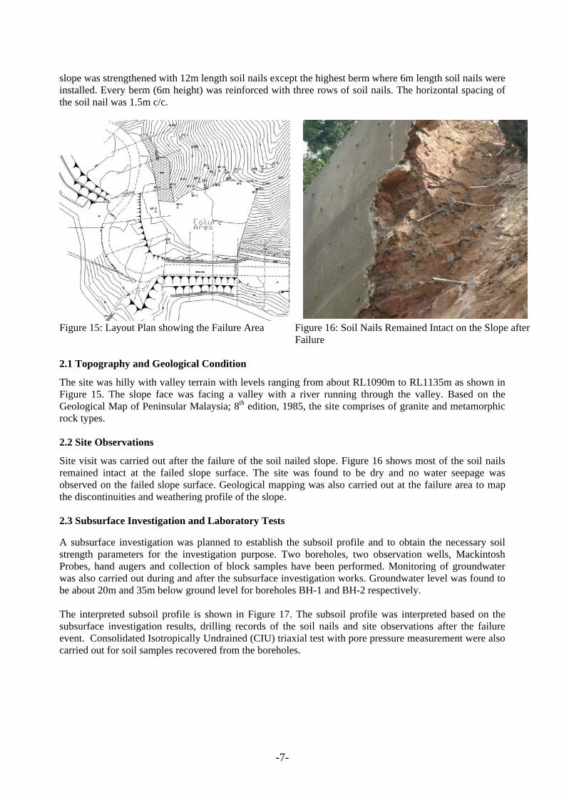
Figure 15: Layout Plan showing the Failure Area Figure 16: Soil Nails Remained Intact on the Slope after
Failure 2.1 Topography and Geological Condition
The site was hilly with valley terrain with levels ranging from about RL1090m to RL1135m as shown in Figure 15. The slope face was facing a valley with a river running through the valley. Based on the Geological Map of Peninsular Malaysia; 8th edition, 1985, the site comprises of granite and metamorphic rock types. 2.2 Site Observations
Site visit was carried out after the failure of the soil nailed slope. Figure 16 shows most of the soil nails remained intact at the failed slope surface. The site was found to be dry and no water seepage was observed on the failed slope surface. Geological mapping was also carried out at the failure area to map the discontinuities and weathering profile of the slope. 2.3 Subsurface Investigation and Laboratory Tests
A subsurface investigation was planned to establish the subsoil profile and to obtain the necessary soil strength parameters for the investigation purpose. Two boreholes, two observation wells, Mackintosh Probes, hand augers and collection of block samples have been performed. Monitoring of groundwater was also carried out during and after the subsurface investigation works. Groundwater level was found to be about 20m and 35m below ground level for boreholes BH-1 and BH-2 respectively. The interpreted subsoil profile is shown in Figure 17. The subsoil profile was interpreted based on the subsurface investigation results, drilling records of the soil nails and site observations after the failure event. Consolidated Isotropically Undrained (CIU) triaxial test with pore pressure measurement were also carried out for soil samples recovered from the boreholes.

-8-
Figure 17: Interpreted Subsoil Profile
Most of the tested samples were classified as very silty gravel/sand. The samples show high composition of coarse material (sand and gravel) content, ranging from about 50% to 90%.
As shown in the interpreted subsoil profile, varying degrees of subsoil weathering was encountered within the soil nailed slope. Due to the difficulties in recovering and testing of relatively harder material (Grade IV and III) to obtain realistic shear strength parameters, the rock mass strength method proposed by Hoek et al (2002) was adopted to derive the equivalent Mohr-Coulomb strength parameters. The Hoek-Brown failure criterion for rock mass is an empirical method which provides rock mass strength parameters by incorporating geological parameters and observations in the failure model. A software “RocLab” was used to input the required geological parameters and generate the Mohr-Coulomb failure envelope. The strength parameters from Hoek-Brown failure criterion was then adopted in the slope stability analysis.
2.4 Rainfall Record
Rainfall record was also obtained from three rain gauge stations nearby to the failure area. No exceptionally heavy rainfall was recorded in two months prior to the failure event.
2.5 Cause of Failure
Based on the site observation, nail tendon failure and pull-out failure were unlikely to be the cause of the failure. The conditions of the soil nails (Figure 16) after failure event indicated that the failure might be highly related to face failure, which was discussed in Section 1.5 of this paper. The Manual for Design and Construction of Soil Nail Walls (1998) states that, “The facing structural design requires provision of adequate concrete thickness, reinforcement and moment capacity to resist the earth pressures applied to the facing span between adjacent nail heads, and provision of adequately sized bearing plates to provide adequate punching shear capacity”. Assessment was then carried out on the facing of the soil nailed slope, which was

-9-
designed to be 100mm thickness (G25) with 2 layers of A6 mesh reinforcement as shown in Figure 18. It was found that the flexural strength and punching shear strength of the facing was grossly inadequate. Therefore, facing failure was deemed imminent.
1
2
3
4
1
2
34
5
6
7
8
9
10
11
12
13
14
15
16
17
18
19
20
21
22
23
24
25
26
27
28
29
30
31
32
33
34
3536
37
38
39
40
41
42
43
44
45
46
47
48
49
50
51
52
53
54
55
56
57
58
59
60
61
62
6364
6566
67
68
69
7071
7273
7475
767778
80
81
85
86
87
1
2
34
5
6
7
8
9
10
11
12
13
14
15
16
17
18
19
20
21
22
23
24
25
26
27
28
29
30
31
32
33
34
3536
37
38
39
40
41
42
43
44
45
46
47
48
49
50
51
52
53
54
55
56
57
58
59
60
61
62
6364
6566
67
68
69
7071
7273
7475
767778
80
81
85
86
87
Description: Soil 1Model: MohrCoulombWt: 18Cohesion: 6Phi: 32
Description: Soil 2Model: MohrCoulombWt: 18Cohesion: 8Phi: 36
Description: Soil 3Model: MohrCoulombWt: 19Cohesion: 70Phi: 27
Description: Soil 4Model: MohrCoulombWt: 20Cohesion: 120Phi: 27
Soil 1
Soil 2
Soil 3
Soil 4
Figure 18: Details of Gunite Facing at Site Figure 19: Stability Analysis Result
Apart from the assessment of the facing failure, slope stability analysis using limit equilibrium method was also carried out to assess the possibility of overall failure. The interpreted subsoil profile, CIU results and strength parameters from Hoek-Brown failure criterion were collectively adopted in the stability analysis model. The stability analysis result (Figure 19) revealed that FOS of the soil nailed slope was only 1.12 which was marginally stable. Such low FOS is not adequate for long-term stability. 2.5 Summary
The investigation has revealed the following findings: a. The main cause of failure was due to inadequate design of the gunite facing of the soil nailed slope. b. The FOS against overall failure is inadequate and was marginally stable. c. Rainfall/groundwater was not a triggering cause to the failure event. 3.0 RECOMMENDATION AND CONCLUSION The following recommendations and conclusions can be made from the investigation of the two case histories of soil nailed slope failures: a. It is necessary to carry out subsurface investigation at high cut area especially if soil nailed slope is to
be constructed. Inspection and examination on the exposed slope material and geological structures should also be carried out during various stages of construction. If the subsoil profile, geological structures or groundwater table are found to be different from the design model, then the design shall be reviewed with the updated information. This design feedbacks and verifications are crucial in order to ensure safety of a soil nailed slope. Sometimes, further design optimisation is possible if the ground condition is more favourable.
b. Engineering assessment shall be carried out for all four potential failure modes: nail tendon failure, nail pull-out failure, facing failure and overall failure for the design of soil nailed slope. The design of the facing is often neglected by designers thinking that its sole purpose of the facing is to protect against surface erosion only and neglect its role as a structural element to resist the earth pressure. It should be noted that the design of facing is especially critical when the soil nailed slope is high and steep. The facing should be designed to resist the earth pressures, bending moment and punching shear force from the pulling of soil nail under the earth pressure. Inadequate facing design could lead to failure of soil nailed slope as depicted in case history B.
FOS=1.12

-10-
c. Representative shear strength parameters should be used for the design of a soil nailed slope. Strength tests such as CIU and direct shear box tests should be carried out to obtain the strength parameters for design. For rock mass, the current available approach still relies on empirical method. The reliability of the method is very much related to the adopted values for the empirical factors with respect to the database of failure case and visual classification based on rock mass characteristic.
REFERENCES British Standard Institution, BS8081:1989 British Standard Code for Ground Anchorages.
Bryne, R.J. et al. (1998) Manual for Design and Construction Monitoring of Soil Nail Wall. Federal Highway Administration of US.
Geological Map (1974), Malaysia Minerals and Geoscience Department. Geological Map (1985), Malaysia Minerals and Geoscience Department.
Hoek, E., Carranza-Torres, C. and Corkum, Brent. (2002) Hoek-Brown Failure Criterion-2002 Edition. INGEOTUNELES, Tunnelling Engineering Series, Vol.7, Chapter 1, pp.35-47.