![Teaching linear accelerator physics using simulation software · 2018. 11. 21. · AAPM TG21 dosimetry protocol[5]. Steering servo Model beam steering servo circuits. Standard beam](https://static.fdocuments.net/doc/165x107/60ac014e80600950426cb443/teaching-linear-accelerator-physics-using-simulation-software-2018-11-21-aapm.jpg)
Analysis and Simulation of a Submarine Steering Control System
162
ANALYSIS AND SIMULATION OF A SUBMARINE STEERING CONTROL SYSTEM Ernest Everett Wessman
-
Upload
morganflexer -
Category
Documents
-
view
227 -
download
0
Transcript of Analysis and Simulation of a Submarine Steering Control System

7/25/2019 Analysis and Simulation of a Submarine Steering Control System
http://slidepdf.com/reader/full/analysis-and-simulation-of-a-submarine-steering-control-system 1/162
ANALYSIS
AND
SIMULATION OF
A
SUBMARINE
STEERING CONTROL SYSTEM
Ernest Everett Wessman

7/25/2019 Analysis and Simulation of a Submarine Steering Control System
http://slidepdf.com/reader/full/analysis-and-simulation-of-a-submarine-steering-control-system 2/162

7/25/2019 Analysis and Simulation of a Submarine Steering Control System
http://slidepdf.com/reader/full/analysis-and-simulation-of-a-submarine-steering-control-system 3/162
NAVAL
POSTGRADUATE
SCHOOL
Monterey,
California
THESIS
Analysis
and Simulation
of
a
Submarine Steering
Control System
by
Ernest
Everett
Wessman
Thesis
Advisor:
R.
H. Nunn
June
1972
Approved
for
Public
Release;
Distribution
Unlimited.

7/25/2019 Analysis and Simulation of a Submarine Steering Control System
http://slidepdf.com/reader/full/analysis-and-simulation-of-a-submarine-steering-control-system 4/162

7/25/2019 Analysis and Simulation of a Submarine Steering Control System
http://slidepdf.com/reader/full/analysis-and-simulation-of-a-submarine-steering-control-system 5/162
Analysis
and
Simulation
of a
Submarine Steering
Control System
by
Ernest Everett Wessman
Ensign,
United
States Navy
B.S.,
M.E.,
University
of
Utah,
1971
Submitted
in partial fulfillment
of
the
requirements for
the degree
of
MASTER OF SCIENCE IN MECHANICAL
ENGINEERING
from
the
NAVAL POSTGRADUATE
SCHOOL
June
1972

7/25/2019 Analysis and Simulation of a Submarine Steering Control System
http://slidepdf.com/reader/full/analysis-and-simulation-of-a-submarine-steering-control-system 6/162

7/25/2019 Analysis and Simulation of a Submarine Steering Control System
http://slidepdf.com/reader/full/analysis-and-simulation-of-a-submarine-steering-control-system 7/162
ABSTRACT
An
existing
computer simulation
of a hydraulic
submarine
steering
control
system
was
analyzed to determine the
source
of
its
unrealistic
behavior, which
included
verifying
mathematical
equations
and
numerical
parameters,
duplicating
the
simulation
on
another computer,
and
investi-
gating the
validity of the assumptions made
in its development. Rudder
turning rate
and
load
pressure
drop
oscillations which were
thought
to
be
unrealistic
were
caused by the neglect
of
significant rudder moments
related to the
control
surface
turning rate. Knowledge of
actual system
performance
was
found
to be
incomplete
and further
research was
suggested.
Potentially
beneficial modifications
in the servovalve
and actuator
simulators
were identified. Continuing
work in the
field of unsteady
rudder behavior
was suggested in order to
improve
simulator
and
actual
system
designs

7/25/2019 Analysis and Simulation of a Submarine Steering Control System
http://slidepdf.com/reader/full/analysis-and-simulation-of-a-submarine-steering-control-system 8/162
7/25/2019 Analysis and Simulation of a Submarine Steering Control System
http://slidepdf.com/reader/full/analysis-and-simulation-of-a-submarine-steering-control-system 9/162
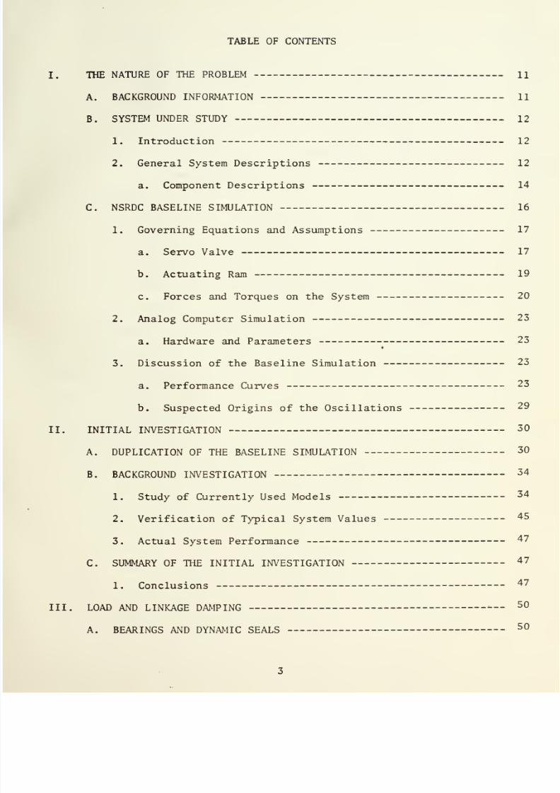
TABLE
OF
CONTENTS
I.
THE
NATURE
OF
THE
PROBLEM
11
A.
BACKGROUND
INFORMATION
11
B.
SYSTEM UNDER
STUDY
12
1. Introduction 12
2. General System
Descriptions
12
a.
Component Descriptions
14
C.
NSRDC BASELINE SIMULATION
16
1.
Governing Equations
and
Assumptions
17
a.
Servo Valve
17
b.
Actuating Ram
19
c. Forces and Torques on
the
System
20
2. Analog Computer Simulation
23
a.
Hardware
and
Parameters
23
*
3.
Discussion
of
the
Baseline Simulation
23
a. Performance
Curves
23
b.
Suspected
Origins
of
the
Oscillations
29
II. INITIAL
INVESTIGATION
30
A. DUPLICATION
OF
THE BASELINE SIMULATION
30
B.
BACKGROUND
INVESTIGATION
34
1. Study of Currently
Used Models
34
2.
Verification
of
Typical System
Values
45
3. Actual System
Performance
47
C.
SUMMARY
OF
THE INITIAL INVESTIGATION
47
1. Conclusions
47
III. LOAD AND
LINKAGE
DAMPING
—
50
A. BEARINGS
AND
DYNAMIC
SEALS
50

7/25/2019 Analysis and Simulation of a Submarine Steering Control System
http://slidepdf.com/reader/full/analysis-and-simulation-of-a-submarine-steering-control-system 10/162
7/25/2019 Analysis and Simulation of a Submarine Steering Control System
http://slidepdf.com/reader/full/analysis-and-simulation-of-a-submarine-steering-control-system 11/162
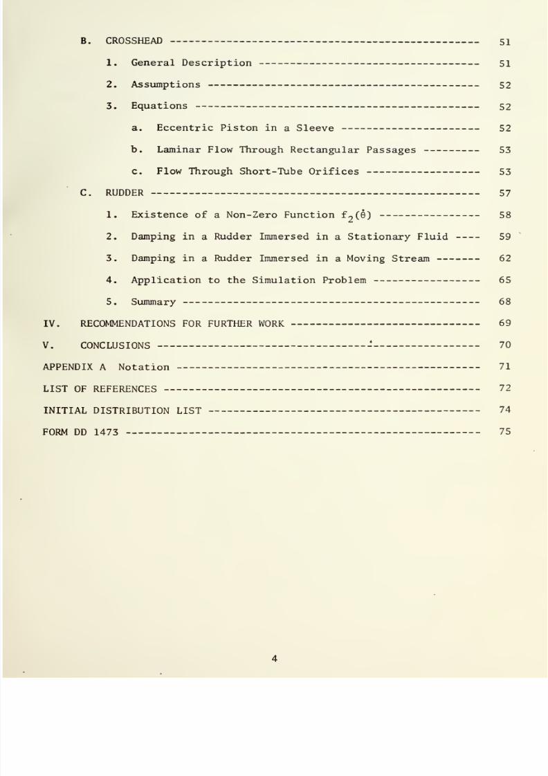
B.
CROSSHEAD
51
1.
General
Description
51
2.
Assumptions
52
3.
Equations
52
a.
Eccentric
Piston
in
a
Sleeve
52
b. Laminar Flow
Through
Rectangular
Passages
53
c.
Flow
Through Short-Tube
Orifices
53
C.
RUDDER
57
1.
Existence
of
a
Non-Zero
Function f
2
(6)
58
2.
Damping
in
a
Rudder Immersed in
a
Stationary
Fluid
59
3.
Damping
in
a
Rudder Immersed
in
a
Moving Stream 62
4. Application
to
the Simulation
Problem
65
5.
Summary
68
IV.
RECOMMENDATIONS FOR FURTHER
WORK
69
V.
CONCLUSIONS
70
APPENDIX
A Notation
71
LIST
OF REFERENCES
72
INITIAL
DISTRIBUTION
LIST
74
FORM
DD
1473
75

7/25/2019 Analysis and Simulation of a Submarine Steering Control System
http://slidepdf.com/reader/full/analysis-and-simulation-of-a-submarine-steering-control-system 12/162

7/25/2019 Analysis and Simulation of a Submarine Steering Control System
http://slidepdf.com/reader/full/analysis-and-simulation-of-a-submarine-steering-control-system 13/162
LIST
OF TABLES
TABLE
I.
SYSTEM
VALUES
25
TABLE
II.
POTENTIOMETER
EXPRESSIONS
AND
SETTINGS-
26

7/25/2019 Analysis and Simulation of a Submarine Steering Control System
http://slidepdf.com/reader/full/analysis-and-simulation-of-a-submarine-steering-control-system 14/162

7/25/2019 Analysis and Simulation of a Submarine Steering Control System
http://slidepdf.com/reader/full/analysis-and-simulation-of-a-submarine-steering-control-system 15/162
LIST OF
DRAWINGS
1.
SUBMARINE
STEERING CONTROL
SYSTEM
—
-
13
2.
SERVOVALVE
—
15
3.
HYDRODYNAMIC
TORQUE BEHAVIOR
FOR
VARIOUS VALUES
OF
K
7
AND
K
g
22
4.
BASELINE
ANALOG COMPUTER
SCHEMATIC DIAGRAM
24
5.
BASELINE
SIMULATION
RESPONSE
6
Q
=
35
DEGREES
33
6.
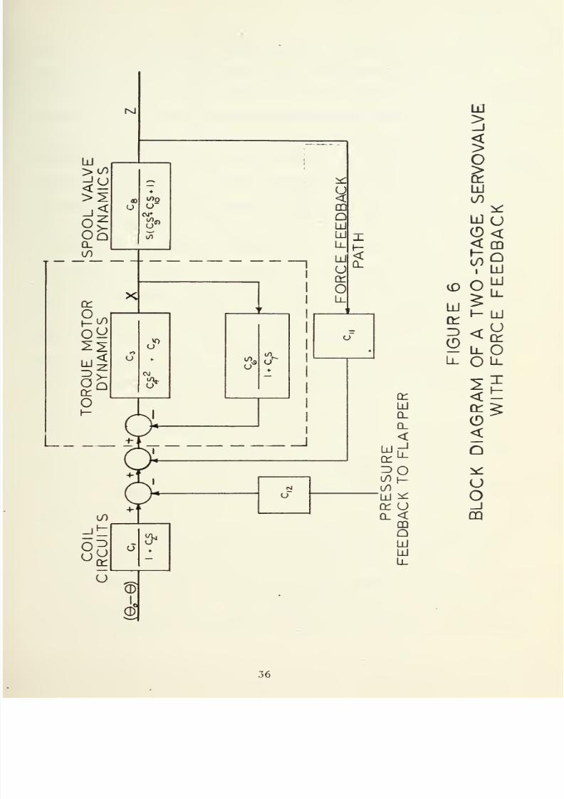
BLOCK DIAGRAM OF A TWO-STAGE SERVOVALVE
WITH
FORCE
FEEDBACK
36
7.
FUNCTIONAL BLOCK DIAGRAM
OF A
SUBMARINE STEERING
CONTROL SYSTEM
38
8. CURVES
OF
SEVERAL
PARAMETERS
OF CI
-
5000
SIMULATION 39
9.
FRICTIONLESS
LOAD
CONDITION,
T
p
= 40
10. CIRCUIT
MODIFICATION
OF
FIG. 4: INTRODUCTION OF
VISCOUS DAMPING
41
11.
VISCOUS DAMPING LEVEL .005
J2
—
,
T
f
=
42
9
max
12.
VISCOUS
DAMPING
LEVEL
.12
J-
—
,
T
c
=
43
ft
r
D
max
13.
TYPICAL CROSSHEAD DESIGN
46
14. CROSSHEAD
TORQUE FOR
VARIOUS HOLE SIZES
55
15.
RUDDER
CONSTRUCTION ASSUMED FOR
STATIONARY
RUDDER
TORQUE
CALCULATION
59
16.
ANALOG
CIRCUIT DIAGRAM
FOR
INTRODUCTION
OF T
R
61
17.
FLAT
PLATE APPROXIMATION
TO
A
RUDDER TURNING
AT
A
CONSTANT RATE
63
18.
A
VERSUS
f*
64
«
m

7/25/2019 Analysis and Simulation of a Submarine Steering Control System
http://slidepdf.com/reader/full/analysis-and-simulation-of-a-submarine-steering-control-system 16/162

7/25/2019 Analysis and Simulation of a Submarine Steering Control System
http://slidepdf.com/reader/full/analysis-and-simulation-of-a-submarine-steering-control-system 17/162
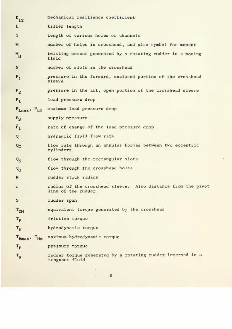
LIST
OF
SYMBOLS
A
actuator
piston
area
A
crosshead area
CH
A
area
of
an incremental
flat
plate
used
in
the
calculation
*
of stationary rudder damping
A'
area of
holes in
crosshead
C
loss coefficient
of
a
short tube
orifice.
Also the
chord
length
of
a rudder.
c
radial
clearance of
a
crosshead in
its
sleeve
Cq
coefficient
of
friction
of
the
stock
bearing
( .„
dimensionless twisting
moment
coefficient
^MHO
quasi-stationary
portion
of
Cj^
D diameter
of
axial
holes
in crosshead
db
dead
band, fraction
of
maximum
*
e
eccentricity of
crosshead
in
sleeve. Also
the
error
signal
I polar moment of
inertia of
the
rudder
K.
amplifier gain coefficient
K
2
flapper centering spring
rate
K,
wand spring rate
K*
pilot stage valve
flow
coefficient
Kc
main
stage
valve
flow coefficient
K,
system
hydraulic
resilience
coefficient
K_
hydrodynamic
load
torque
coefficient
Kg
hydrodynamic
load
torque
coefficient
K
q
lift
coefficient
K,
Q
seal
friction
coefficient
K
drag
coefficient

7/25/2019 Analysis and Simulation of a Submarine Steering Control System
http://slidepdf.com/reader/full/analysis-and-simulation-of-a-submarine-steering-control-system 18/162
7/25/2019 Analysis and Simulation of a Submarine Steering Control System
http://slidepdf.com/reader/full/analysis-and-simulation-of-a-submarine-steering-control-system 19/162
K
mechanical
resilience
coefficient
12
L
tiller length
1
length
of various holes
or
channels
M
number
of
holes
in crosshead,
and
also
symbol
for
moment
M
twisting
moment
generated by
a
rotating
rudder
in
a
moving
H
fluid
N
number
of
slots
in
the
crosshead
P.
pressure
in the
forward,
enclosed
portion
of
the
crosshead
sleeve
?2
pressure in
the
aft, open portion
of
the
crosshead sleeve
P.
load
pressure
drop
Pj_
,
P^
m
maximum
load pressure drop
Pg supply
pressure
Py rate of
change
of
the
load
pressure drop
Q
hydraulic
fluid flow
rate
flow rate through
an
annulus
formed
between
two
eccentric
cylinders
Q<,
flow
through
the
rectangular slots
Q~
flow
through
the crosshead
holes
R
rudder
stock radius
r radius
of
the
crosshead
sleeve. Also distance
from
the pivot
line
of
the rudder.
S
rudder span
T
r
„
equivalent
torque
generated by
the
crosshead
T_
friction
torque
T„
hydrodynamic
torque
^Hmax*
^Hm
maximum
hydrodynamic
torque
Tp
pressure
torque
1-
rudder
torque
generated by
a
rotating
rudder
immersed in a
stagnant
fluid

7/25/2019 Analysis and Simulation of a Submarine Steering Control System
http://slidepdf.com/reader/full/analysis-and-simulation-of-a-submarine-steering-control-system 20/162
7/25/2019 Analysis and Simulation of a Submarine Steering Control System
http://slidepdf.com/reader/full/analysis-and-simulation-of-a-submarine-steering-control-system 21/162
T
s
system sliding
friction
torque
U
velocity
of the fluid
past
the
rudder
V
ship
velocity
V_
maximum
ship
velocity
W
weight
of
rudder
w
width of rectangular
slot
x
valve flapper displacement
y
hydraulic
actuator displacement
•
y
hydraulic
actuator
velocity
y
max
,
y
m
maximum
hydraulic actuator
displacement
•
y
maximum
actuator
velocity
z
valve spool
displacement
•
z valve
spool velocity
z'
effective valve spool
displacement after compensation
for
spool
dead
zone effects
z effective valve spool
displacement
after compensation for
spool
dead zone and multiple
flow
gain effects
a
rudder angle
of attack to
oncoming
stream
time
scaling
factor
for analog program
ACj^
rudder
turning rate
-
dependent
portion
of Cj^
AMjj
rudder turning rate
-
dependent portion
of
the
rudder
twisting
moment
v
kinematic
viscosity
V
absolute
viscosity
Q
dt
9
rudder angle
®max
®m
maximum
rudder
angle
9
rudder angular
velocity

7/25/2019 Analysis and Simulation of a Submarine Steering Control System
http://slidepdf.com/reader/full/analysis-and-simulation-of-a-submarine-steering-control-system 22/162

7/25/2019 Analysis and Simulation of a Submarine Steering Control System
http://slidepdf.com/reader/full/analysis-and-simulation-of-a-submarine-steering-control-system 23/162
ACKNOWLEDGEMENT
The
writer
wishes
to
thank
his
thesis
advisor,
Associate
Professor
R.
H.
Nunn
of the
Naval
Postgraduate School's
Mechanical
Engineering
Department
for his
patience
and
assistance. He also wishes
to
acknow-
ledge
the
contributions
of
the
following:
Mr.
Guy
Johnson,
Naval
Ship
Research and Development
Center
Mr.
Walter Blumberg, Naval Ship
Research
and Development
Center
Mr.
Ralph Leibowitz, Naval
Ship
Research
and Development
Center
Mr. Lee
land Smith, Mare Island Naval Shipyard
Mr.
William Kendall,
Mare
Island Naval
Shipyard
Professor
George
Thaler, Naval Postgraduate School
Mr.
Robert Limes, Naval Postgraduate School
10

7/25/2019 Analysis and Simulation of a Submarine Steering Control System
http://slidepdf.com/reader/full/analysis-and-simulation-of-a-submarine-steering-control-system 24/162
7/25/2019 Analysis and Simulation of a Submarine Steering Control System
http://slidepdf.com/reader/full/analysis-and-simulation-of-a-submarine-steering-control-system 25/162
I.
THE
NATURE
OF
THE PROBLEM
A.
BACKGROUND INFORMATION
In
1971,
the
Naval
Ship
Research
and
Development
Center (NSRDC)
, in
Annapolis,
Maryland,
identified
a potential stability
problem
in an
electrohydraulic
servosystem which was
being developed.
The control
system
was
being
designed
to
control
the
movement
of
a
submarine's
rudder
in accordance
with
commands from
the
helmsman.
The
NSRDC
developed an
analog
computer simulation
(hereafter
referred
to
as
the
baseline
simu-
lation ) which incorporated many
of
the
characteristics of an
actual
hydraulic control system, including friction, hydraulic and mechanical
characteristics, servovalve behavior, and
interdependence of
elements
necessary
to create
a
simulation
of
the
actual system. The
simulation
was
based
on
equations
developed
to
model
an existing
system
used
in
the USS PARGO (SSN
650)
.
Provisions
were made
so
that the
simulation
could
be
adjusted
by
changing
values
of
the
various components
of the
model,
in
order
to
conform to possible
changes of the parameters
of
the
system under
development,
such
as
changes
in
dimensions,
materials,
and
operating conditions. The provision
for
adjustment of
the
simulator
parameters
also allowed
simulation of
other existing hydraulic
systems
of
this type.
All parameters
which
were assumed to
be
of
significant
impact on the performance
of the
system
were
incorporated
into the
simulation.
When the
simulator parameters
were arranged to
model
the
performance
of
the system under
development, the
model
did
not
conform
to
expected
system
behavior;
oscillations in
pressures and
control
surface
turning
11

7/25/2019 Analysis and Simulation of a Submarine Steering Control System
http://slidepdf.com/reader/full/analysis-and-simulation-of-a-submarine-steering-control-system 26/162

7/25/2019 Analysis and Simulation of a Submarine Steering Control System
http://slidepdf.com/reader/full/analysis-and-simulation-of-a-submarine-steering-control-system 27/162
rates
were
observed which had not
been
observed
in similar systems
in
use.
Further
investigations
failed
to reveal
any obvious
errors in
the
'
simulation,
or
deficiencies
in the parameters which
were believed
to be
of
significant
impact
on the
performance
of
the
system.
This thesis
is
a result of a
project initiated
in support of
the
simulation
attempt
at
the
NSRDC.
The purpose
of this
project
was
to
determine the
reasons
for the
observed
behavior of the hydraulic
system
model, and to develop appropriate
modifications
and
refinements of
the
baseline simulation, in order
to
more closely model actual
system
performance
B.
SYSTEM UNDER STUDY
1.
Introduction
The
following
paragraphs describe
the
general
characteristics of
the
idealized system
that
the
NSRDC
used
in
the
development
of
its
simula-
tion.
The
description does
not
completely
describe any
real
system.
Rather,
it is
a
model which
was
designed
to
include
all of
the
steering
system characteristics
that
were expected to be of
significant
impact on
the
performance
of
the
system.
2. General
System
Descriptions
The
steering system
(Figure
1)
included
the
servovalve,
connecting
tubing,
actuating
ram, mechanical linkages,
rudder,
and minor
components.
The
operation of
the
system is described
below.
(Numbers
in
parentheses
refer
to corresponding labeled parts on
Figure
1.)
A
desired
change
of rudder
angle
is
initiated
by
moving
the
control
wheel
(1)
by hand,
which generates
an
electrical
signal
having
a
voltage
proportional
to
the
degree
of
movement. This
voltage
representing
the
desired
control surface angle is then
compared
with a
voltage
proportional

7/25/2019 Analysis and Simulation of a Submarine Steering Control System
http://slidepdf.com/reader/full/analysis-and-simulation-of-a-submarine-steering-control-system 28/162

7/25/2019 Analysis and Simulation of a Submarine Steering Control System
http://slidepdf.com/reader/full/analysis-and-simulation-of-a-submarine-steering-control-system 29/162

7/25/2019 Analysis and Simulation of a Submarine Steering Control System
http://slidepdf.com/reader/full/analysis-and-simulation-of-a-submarine-steering-control-system 30/162
7/25/2019 Analysis and Simulation of a Submarine Steering Control System
http://slidepdf.com/reader/full/analysis-and-simulation-of-a-submarine-steering-control-system 31/162
to
the
actual
position
of
the
hydraulic
ram
(6)
. An error
signal
is
generated
which
approximates the
difference
between
the
desired
and
actual
rudder positions
(2)
.
This
signal
actuates an electric
torque
motor
(3)
in
the
servovalve,
which
moves
a
small
flapper
(4)
located
in
the
narrow
space
between
two nozzles,
causing
an increase
in the pilot
pressure
on one nozzle, and
a
decrease
on
the other.
This difference
in
pressure
causes
the
spool
valve
(5)
to
move,
thereby permitting
pressure
and
subsequent
fluid flow
to
be applied
to the hydraulic ram
(6)
,
resulting
in a correcting
movement
of
the
control
surface
(7)
through
the mechanical linkage.
The value of
the
error
signal
is modified by
movement
of the hydraulic ram, and the entire
process
is continuously
repeated
until
the
error signal is
reduced
to zero. As
the
error signal
decreases, the
servovalve
closes,
control
surface movement ceases, and
equilibrium
is
established
at
the
new position.
*
a.
Component
Descriptions
(1)
Servovalve
. The servovalve
(Figure
2)
used
in
a
submarine
steering control system is a
two-stage,
force
feedback
model,
incorporating
a torque
motor
actuated by an
electrical error
signal; a
flapper-type
pilot valve, the
flapper
itself also
serving as
the
armature
of the
torque
motor;
and
a
spool
valve,
actuated by
the
fluid
flow
caused by
the
movement
of the
pilot
flapper
valve. Movement
of the spool
results
in the
direction
of fluid
flow
to the
actuating
ram.
(2)
Actuator
.
The actuator
is a
linear,
two-way
hydraulic
ram. The
NSRDC
assumed in modeling
the
actuator that
it
was
of
compensated
construction;
that is, it
was
designed
with equal
effective
areas
on
both
sides of the
piston.
O-rings are
incorporated
into
the
design
of
the
actua-
tor,
eliminating
essentially
all
leakage from
one
side
of
the
piston
to
the
other.

7/25/2019 Analysis and Simulation of a Submarine Steering Control System
http://slidepdf.com/reader/full/analysis-and-simulation-of-a-submarine-steering-control-system 32/162

7/25/2019 Analysis and Simulation of a Submarine Steering Control System
http://slidepdf.com/reader/full/analysis-and-simulation-of-a-submarine-steering-control-system 33/162
b>,
2
LU
bJ
<
—
a:
Ll
lu

7/25/2019 Analysis and Simulation of a Submarine Steering Control System
http://slidepdf.com/reader/full/analysis-and-simulation-of-a-submarine-steering-control-system 34/162

7/25/2019 Analysis and Simulation of a Submarine Steering Control System
http://slidepdf.com/reader/full/analysis-and-simulation-of-a-submarine-steering-control-system 35/162
(3)
Mechanical
Linkage .
The linkage
connecting
the hydraulic
ram to
the
rudder
consists
of
a
long
shaft, support bearings,
a packing
at
the
penetration
of
the pressure
hull,
a
crosshead
at the end
of the
shaft
opposite
the
ram,
and
a
rod
connecting
the
crosshead
to
the
rudder
tiller.
The
crosshead provides
a supported, pinned
joint
from
which
the
connecting rod originates. It
was assumed
to be constrained from
lateral
movement by
an
open-ended
sleeve
which
was
flooded with
sea water.
(4)
Rudder
.
The
rudder
is composed
of two
portions,
an upper
rudder
and a lower
rudder,
interconnected
to the
tiller by a single shaft,
and located
on the
top and bottom
of
the
ship's hull, respectively. The
rudder
is symmetric along the chord length, and
is
designed
for operation
within
the
range
of left
35 degrees rudder
to
right
35 degrees.
(5)
Other
Components
. Other components
include piping;
an
electric
transmitter
associated
with the control
wheel; an
error
feedback
*
servo
associated
with
the
actuator;
a
hydraulic pressure supply
which is
assumed for
design
purposes to
be constant in pressure,
and
not subject
to
influence
by
steering system
conditions;
and a petroleum-base
hydraulic
fluid.
C.
NSRDC BASELINE SIMULATION
The following
sections describe
the
work done at the
NSRDC
in
order
to simulate the submarine steering
control system.
The
governing
equations
for
each of
the components
are
stated
as they
were
derived by the
NSRDC,
along
with
any
assumptions that
were explicitly
stated.
A
schematic
circuit
diagram
of the analog
computer
arrangement is
presented,
and
comments
from
the
NSRDC
about
the
nature
of the
problem
and
suspected
origins
of
the
oscillation
are
stated.

7/25/2019 Analysis and Simulation of a Submarine Steering Control System
http://slidepdf.com/reader/full/analysis-and-simulation-of-a-submarine-steering-control-system 36/162
7/25/2019 Analysis and Simulation of a Submarine Steering Control System
http://slidepdf.com/reader/full/analysis-and-simulation-of-a-submarine-steering-control-system 37/162
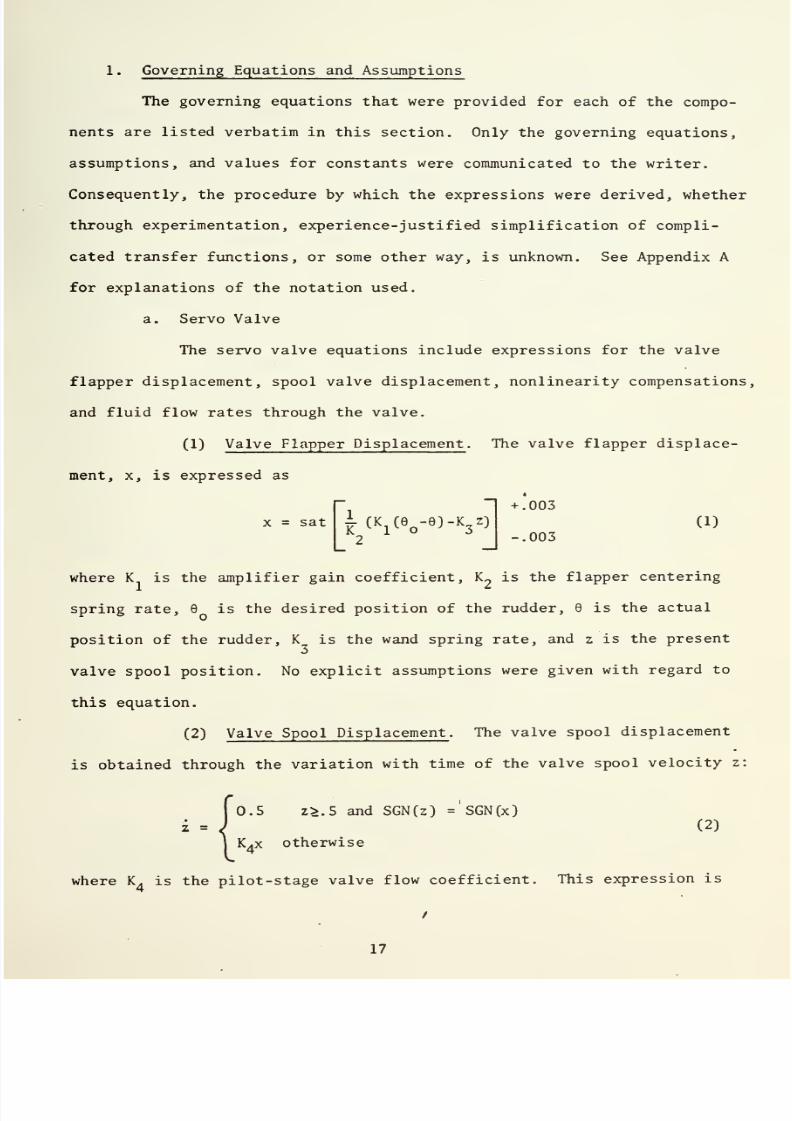
1.
Governing Equations
and
Assumptions
The
governing
equations that
were
provided
for
each
of the compo-
nents
are
listed
verbatim in
this section. Only
the
governing
equations,
assumptions,
and
values
for
constants
were communicated
to
the
writer.
Consequently, the procedure by which
the expressions were
derived,
whether
through
experimentation,
experience-
justified simplification
of compli-
cated
transfer
functions, or
some
other
way,
is
unknown.
See Appendix
A
for
explanations of
the
notation
used.
a.
Servo
Valve
The
servo
valve
equations include expressions for
the valve
flapper
displacement,
spool
valve displacement,
nonlinearity compensations,
and
fluid flow rates through the
valve.
(1)
Valve
Flapper Displacement
.
The
valve
flapper
displace-
ment, x, is
expressed
as
+
.003
x
=
sat
I
CK(e
o
-e)-K
3
z)
2
CD
-.003
where K is the
amplifier gain
coefficient,
K
2
is
the
flapper
centering
spring
rate,
9 is
the
desired
position of the
rudder, 9
is
the
actual
position
of
the
rudder,
K
is
the
wand spring
rate,
and
z
is
the
present
valve
spool
position. No explicit
assumptions
were
given
with
regard to
this
equation.
(2)
Valve
Spool
Displacement
. The
valve
spool
displacement
is
obtained
through
the
variation
with
time of
the
valve
spool
velocity
z
0.5 z^.5 and
SGN(z) ='sGN(x)
(2)
K
4
x
otherwise
where K.
is
the
pilot-stage
valve
flow coefficient.
This
expression
is
/

7/25/2019 Analysis and Simulation of a Submarine Steering Control System
http://slidepdf.com/reader/full/analysis-and-simulation-of-a-submarine-steering-control-system 38/162

7/25/2019 Analysis and Simulation of a Submarine Steering Control System
http://slidepdf.com/reader/full/analysis-and-simulation-of-a-submarine-steering-control-system 39/162
best
explained
by
stating
that
the spool
velocity is
proportional
to the
flapper
valve
displacement, until
the spool
is fully displaced against
the
valve body,
where the movement
must of
course
cease.
The
velocity
again
becomes
non-zero
only if
the
direction
of
movement
is
reversed,
and
the valve is allowed
to travel
away
from
the hard restraining block.
Nonlinear
effects
in
the
valve,
such as
varying
flow gain
(i.e.,
flow
is not proportional
to
spool
displacement, due
to
the shape
of
the ports used
in
the
spool valve), spool friction,
deadband,
and
torque
motor
hysteresis
are
included
in
the next equations.
Dead
band
is
included
in the system through
the
implementa-
tion
of
the
following
equations:
r
z
-
db
where
z
>db,
z>0
t
z
=
\
z
+
db where |zl>db,
z<0 (3)
if
-db<z<db
4
where z' is the valve
spool
displacement
after
adjustment for spool
dead
zone.
These
expressions
give the
effective
spool
displacement,
i.e.,
adjust
the
spool
displacement
to
the value it
would have
for the
given
flow
if no
dead
zone
were
constructed
in
the
valve.
Multiple
flow
gain is
accommodated
by
combining
z'
with
z»i
z'l
:
z
M
=
.5z'
+
.5z'l
z'l
. (4)
where
z
is
the
valve spool
displacement
after
spool
dead
zone,
and
after
multiple
flow gain.
Compensation
for
other
nonlinearities
such
as
spool
friction
and torque
motor
hysteresis
may
have been accomplished
through
adjustment of
the
coefficients in
the
equations
for
spool
dead
band,
and

7/25/2019 Analysis and Simulation of a Submarine Steering Control System
http://slidepdf.com/reader/full/analysis-and-simulation-of-a-submarine-steering-control-system 40/162

7/25/2019 Analysis and Simulation of a Submarine Steering Control System
http://slidepdf.com/reader/full/analysis-and-simulation-of-a-submarine-steering-control-system 41/162
multiple
flow gain. No
additional
expressions
for
these
nonlinearities
were given.
(3)
Flow Equation
. The
flow
rate
in the spool
is
related
to
the
corrected
spool
displacement
z ,
the load pressure
drop
Pr
, and
the
supply
pressure
P
by
the following
expression:
Q
=
z K
5
sgn(P
s
-sgn(z)P
L
)
J
P
s
-
sgn(z)P
L
(5)
where K^
is
the
main-stage
valve flow coefficient.
No
explicit
assumptions
were
listed for
this
equation,
b. Actuating Ram
The
position
of
the
actuating ram
is
described
in
two
ways;
by
the
position of
the rudder itself,
and by the integral
of the
flow
rate
which
has passed
through
the valve.
(1)
Ram Position in Terms of
Rudder Position
. The ram position
y
is related
to
the
rudder position,
with
correction
for
mechanical resilience
in the
linkage,
by
APt
y
=
LsinG
+
p
—
. (
6
)
K
12
where L is
the
length
of the tiller,
is
the rudder
angle
in
degrees,
K
is the mechanical resilience coefficient of the system,
and
A is the
actuator
piston
area.
(2)
Ram
Velocity
Expressed in
Terms of
Pressure
Change and
Flow .
The NSRDC
determined that
the
ram
velocity,
flow
rate,
and load
pressure
have
the following
relationship
to one another:
Q
=
-Ay
+
K
6
P
L
(7)
where K
is the
system
hydraulic
resiliance,
and
P, is
the
rate
of
change
of load
pressure
drop.

7/25/2019 Analysis and Simulation of a Submarine Steering Control System
http://slidepdf.com/reader/full/analysis-and-simulation-of-a-submarine-steering-control-system 42/162

7/25/2019 Analysis and Simulation of a Submarine Steering Control System
http://slidepdf.com/reader/full/analysis-and-simulation-of-a-submarine-steering-control-system 43/162
In
the development
of
these
equations
it was assumed
that
there
was no leakage
from
the
control
valve
to the
actuating
cylinder
at
line
connections,
seals, and
so
forth, and
that there was
no
internal
leakage
in
the
actuating
cylinder
itself.
Also,
it
was
assumed
that
a
compensated actuator
was used; that
is, an actuator was
used in which
both
areas, on opposite
sides of
the piston,
were
equal,
c. Forces
and
Torques
on the System
All
forces on the system were
expressed in
terms
of
the
equiva-
lent
torques
which were placed
on
the rudder
structure. A moment balance
can then
be written:
16*
=
Tp
+
T
H
+
T
F
(8)
where
I is the
polar
moment of
inertia of
the rudder
mass and the
included
water mass,
9
is
the
angular
acceleration
of
the rudder, T_
is
the torque
developed
as
a
result
of
the
pressure
drop across.
the
actuator,
T^
is
the
hydrodynamic
torque,
and Tp
is the friction
torque.
Each
torque
will now
be
discussed
in
more detail.
(1)
Friction Torque
. T
p
is
the most
complicated
of
the
torques
to
describe. It is the
combined friction
torques
from the
shaft
seals,
the
resultant of
the
normal force
on the
rudder bearing
surface,
and
any other
sources
of sliding
(coulomb) friction
present
in
the system.
Stationary
objects
in contact
with each other
stick together
until
subjected
to
forces
larger than the
friction
force present
between
the
objects.
Additionally,
the level
of
applied force
necessary
to
sustain
movement
at very
low
speeds
usually
exceeds the
force
needed at
higher
velocities.
In
order to
model
.these system
characteristics,
the
NSRDC
developed
the
following
expressions
for
T
F
:

7/25/2019 Analysis and Simulation of a Submarine Steering Control System
http://slidepdf.com/reader/full/analysis-and-simulation-of-a-submarine-steering-control-system 44/162
7/25/2019 Analysis and Simulation of a Submarine Steering Control System
http://slidepdf.com/reader/full/analysis-and-simulation-of-a-submarine-steering-control-system 45/162
-(T
H+
T
p
)
if
|VT
p
|<T
s
|
.^
Tp=
^
-T
s
sgn(T
H+
T
p
)
if |T
H+Tl
J>Tj)
6
'
^
-T
c
sgn(6) ie|>e
where
e
is
theoretically zero,
but in practice
is
set
to approximately
0.2
percent of
the maximum
angular
velocity
of
the rudder. T
=
kTg,
where
k
is slightly
less than one, typically
0.95,
and
T<,
is
expressed
by
T
S
=
C
D
R
w
+
/(K
9
e)
2
+K
11
e+A-P
L
)
+
K
io
(
10
)
where
Cp is
the coefficient
of friction
of
the
stock bearing,
W
is the
weight
of
the rudder, R is the
rudder
stock
radius, Kg
is
the
lift co-
efficient of
the
rudder,
K,-, is the drag coefficient of the
rudder,
and
K.
is
the
seal friction
coefficient.
It
should
be
noted that the NSRDC
equation
for
friction
torque
did not
include
any terms
for
damping
pro-
portional
to
angular
velocity of the rudder surface.
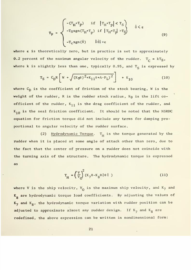
(2)
Hydrodynamic Torque
.
T is the torque
generated by the
rudder
when
it is
placed
at
some
angle
of attack other than
zero,
due to
the
fact that
the
center of
pressure on a
rudder
does
not coincide
with
the
turning
axis of
the
structure. The
hydrodynamic
torque
is
expressed
as
2
T
H
=
(y
(
v
Mc
8
e,e|
>
(n)
where V
is
the
ship
velocity,
V is
the maximum
ship
velocity,
and Ky
and
K
are
hydrodynamic
torque
load
coefficients.
By
adjusting
the
values
of
8
K_ and K
g
,
the
hydrodynamic
torque
variation
with rudder
position
can
be
adjusted to
approximate
almost
any rudder
design.
If K_ and
K
g
are
redefined,
the
above
expression
can
be written
in
nondimensional
form:

7/25/2019 Analysis and Simulation of a Submarine Steering Control System
http://slidepdf.com/reader/full/analysis-and-simulation-of-a-submarine-steering-control-system 46/162

7/25/2019 Analysis and Simulation of a Submarine Steering Control System
http://slidepdf.com/reader/full/analysis-and-simulation-of-a-submarine-steering-control-system 47/162
1.00
5 10
15
20 25 30
RUDDER
ANGLE
0,
IN
DEGREES
FIGURE
3
HYDRODYNAMIC
TORQUE
BEHAVIOR
FOR
VARIOUS
VALUES
OF K
?
AND K
Q

7/25/2019 Analysis and Simulation of a Submarine Steering Control System
http://slidepdf.com/reader/full/analysis-and-simulation-of-a-submarine-steering-control-system 48/162

7/25/2019 Analysis and Simulation of a Submarine Steering Control System
http://slidepdf.com/reader/full/analysis-and-simulation-of-a-submarine-steering-control-system 49/162
T
Hmax
7
\
max/
8
V
max
max
(12)
where
T„
is
the
maximum
hydrodynamic
torque
corresponding
to
Vq,
and
9
max
is
the maximum
rudder
angle.
See
Figure 3 for
curves
of
T„/T
H
for
varying
values of K_
and
K
. It
can
be seen
that a variety of rudder
torque characteristics
can
be simulated
by adjustment of K
7
and K
R
.
(3)
Pressure Torque
. The
pressure
torque T
p
is the torque
that is placed
on
the
stock of
the
rudder by the hydraulic ram, through
the
connecting
linkage.
It
can be
expressed
as
T
=
LAP
L
cos
6
,
(13)
where
L is
the
tiller
length,
A
is
the area
of
the
actuator piston,
and
P, is the load
pressure
drop.
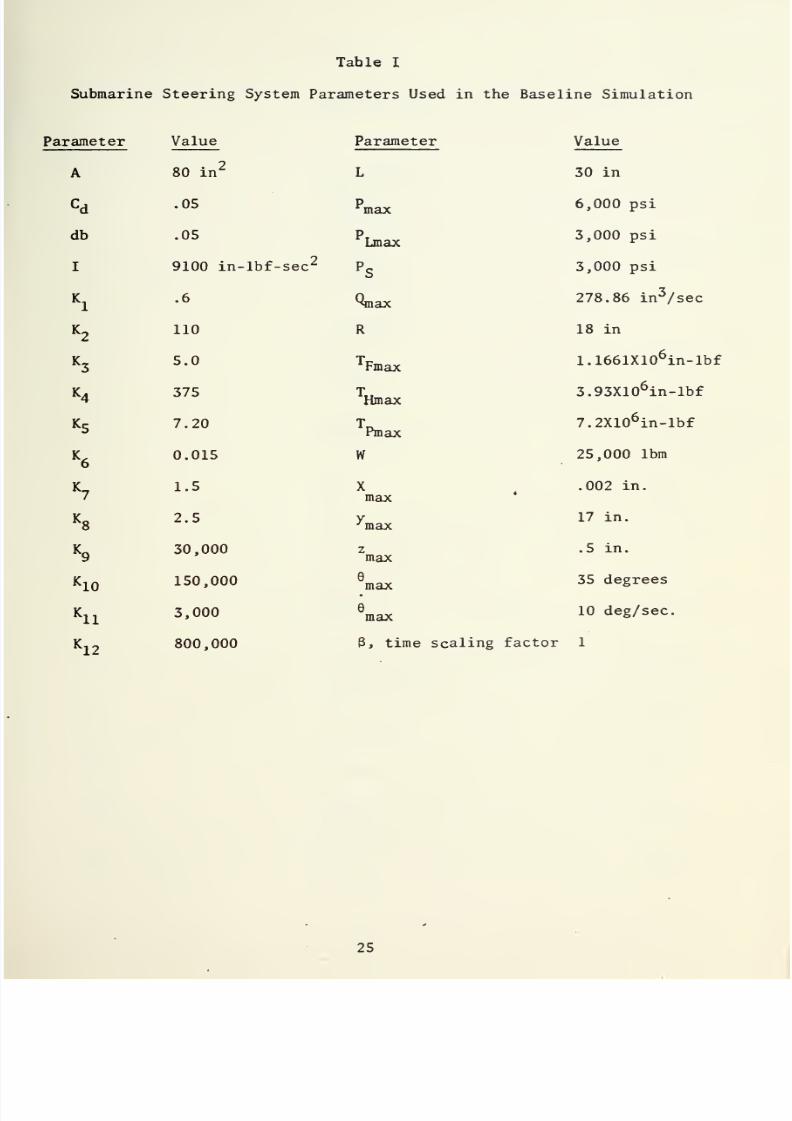
2.
Analog
Computer
Simulation
a.
Hardware
and
Parameters
Figure
4
is a
schematic diagram of
the
analog
computer program
which
was
designed to
model
the governing
equations.
Table I gives a list
of typical
system
dimensions
and other parameters
which were used to
set
simulation
values. Table II
gives
a list
of
the
potentiometer
settings
for
the
values listed in Table I,
and
also lists the
expressions
which
were used to develop the settings.
3.
Discussion of
the
Baseline
Simulation
a.
Performance
Curves
Examination of
sample recordings
obtained
from the
NSRDC
showed
that
oscillations
in
velocity and
pressure
were
present
in
the
simulation
outputs.
The
NSRDC
indicated
that
the
oscillation
appeared
to be
a function
of
the
inertia
of
the
steering
linkage,
ram,
and
rudder,
and
of
the
system mechanical
and
hydraulic
resiliences.
Variation
of

7/25/2019 Analysis and Simulation of a Submarine Steering Control System
http://slidepdf.com/reader/full/analysis-and-simulation-of-a-submarine-steering-control-system 50/162

7/25/2019 Analysis and Simulation of a Submarine Steering Control System
http://slidepdf.com/reader/full/analysis-and-simulation-of-a-submarine-steering-control-system 51/162

7/25/2019 Analysis and Simulation of a Submarine Steering Control System
http://slidepdf.com/reader/full/analysis-and-simulation-of-a-submarine-steering-control-system 52/162
7/25/2019 Analysis and Simulation of a Submarine Steering Control System
http://slidepdf.com/reader/full/analysis-and-simulation-of-a-submarine-steering-control-system 53/162
Table
I
Submarine Steering System
Parameters Used in
the
Baseline
Simulation
Parameter
Value
Parameter
A
80
in
2
L
C
d
.05
p
max
db
.05 p
Lmax
I
9100 in-lbf-sec
2
p
s
K
i
.6
Qmax
K
2
110
R
K
3
5.0
T
Fmax
K
4
375
T
Hmax
K
S
7.20
T
Pmax
K
6
0.015 W
K
T
1.5
X
7
max
K
8
2.5
y
'max
K
9
30,000
z
max
K
10
150,000
e
max
K
ll
3,000
e
max
K,
7
800,000
3,
time
s
Value
30 in
6,000 psi
3,000
psi
3,000
psi
278.86 in
3
/sec
18
in
1.1661X10
6
in-lbf
3.93X10
6
in-lbf
7.2X10
6
in-lbf
25,000
lbm
.002
in.
17 in.
.5
in.
35
degrees
10
deg/sec.

7/25/2019 Analysis and Simulation of a Submarine Steering Control System
http://slidepdf.com/reader/full/analysis-and-simulation-of-a-submarine-steering-control-system 54/162

7/25/2019 Analysis and Simulation of a Submarine Steering Control System
http://slidepdf.com/reader/full/analysis-and-simulation-of-a-submarine-steering-control-system 55/162
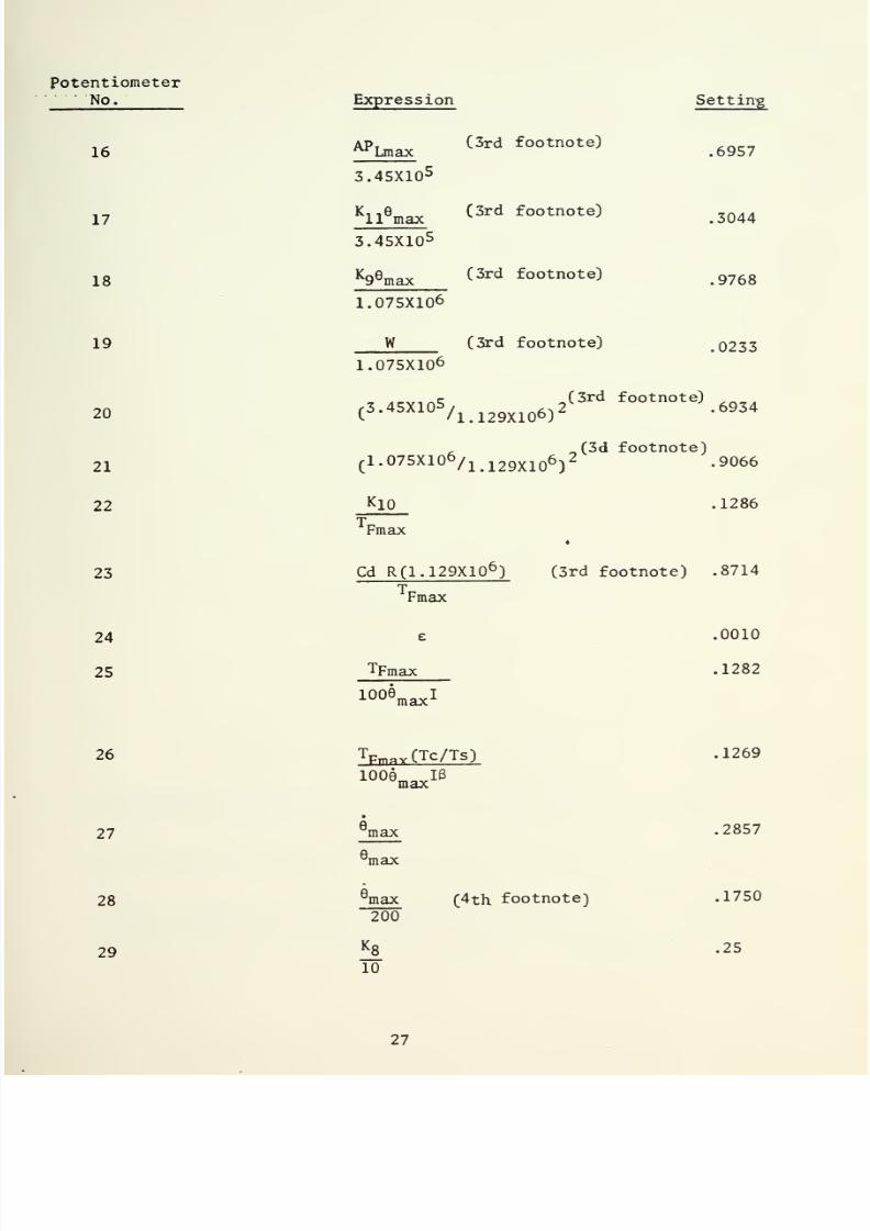
Table
II
Potentiometer Expressions
and Settings
for
Baseline
Simulation
(See Fig.
4)
Potentiometer
No.
6
7
8
9
10
11
12
13
14
15
Expression
Ml
100K
2*max
Vi
100K
2
x
max
Simulation
Technique
K
4
x
max
10z
maxB
K
3
2
max
100K
9
x
mav
I
max
db
db
multiple
flow
gain
multiple
flow gain
max (1st
footnote)
10
K
6
P
L
3
ALe
max
Gr/180)(2nd
footnote)
20
K
6
Pl^
3
Lmax/p
max
Ps
/Pmax
AP
Lmax
K
i
2
y,
max
Setting
.9546
.9546
.1
.1500
.1136
.05
.05
.5
.5
.406
.4654
.5000
.5
.0177
.8824
2y,
max

7/25/2019 Analysis and Simulation of a Submarine Steering Control System
http://slidepdf.com/reader/full/analysis-and-simulation-of-a-submarine-steering-control-system 56/162
7/25/2019 Analysis and Simulation of a Submarine Steering Control System
http://slidepdf.com/reader/full/analysis-and-simulation-of-a-submarine-steering-control-system 57/162
Potentiometer
No.
16
17
18
19
26
27
28
29
Expression
Setting
^Lmax
(3rd
footnote)
.6957
3.45X10
5
K
ll
9
max
(3rd
footnote)
.3044
3.45X10
5
K
9
e
max
(3rd
footnote)
.9768
1.075X10⁶
W
(3rd
footnote)
.0233
1.075X10^
c
(3rd
footnote)
20
(
3 - 45X105
/l.
12
9X10⁶)
2 -
6934
,
„(3d
footnote)
21
C
l.
075X10
6
/i.i29X10
6
)
2
-
9066
22
K
10
.1286
23
24
25
T
Fmax
4
Cd
R(1.129X10
6
)
(3rd
footnote)
.8714
T
Fmax
e
.0010
TFmax
.1282
K^max
1
T
PmaY
(Tc/Ts)
.1269
100e
m
IB
max
•
max
.2857
e
max
e
max
(4th
footnote)
.1750
200
*8
.25
10

7/25/2019 Analysis and Simulation of a Submarine Steering Control System
http://slidepdf.com/reader/full/analysis-and-simulation-of-a-submarine-steering-control-system 58/162

7/25/2019 Analysis and Simulation of a Submarine Steering Control System
http://slidepdf.com/reader/full/analysis-and-simulation-of-a-submarine-steering-control-system 59/162
Potentiometer
No.
Expression
Setting
30
*7
10
L
pm
10
T
Fmax
.15
31
T
Hmax
.3370
10T
Fmax
32
T
pmax
.6175
1. This
expression
was
later
found
to
be
incorrect. See
the text,
Initial Investigation.
2. This
expression was
later found
to be
incorrect.
See
the
text,
Initial
Investigation.
3. Numbers
appearing in
the
numerators
or
denominators of
these
expressions
represent
scaling
values calculated by
the
NSRDC.
4.
Adjustment
for
SIN
-
COS generator
design requirements.
28

7/25/2019 Analysis and Simulation of a Submarine Steering Control System
http://slidepdf.com/reader/full/analysis-and-simulation-of-a-submarine-steering-control-system 60/162

7/25/2019 Analysis and Simulation of a Submarine Steering Control System
http://slidepdf.com/reader/full/analysis-and-simulation-of-a-submarine-steering-control-system 61/162
these
parameters
modified
the fundamental frequency
of
the
oscillation,
but
did not
eliminate
it. It
was found
that
the oscillation could be
eliminated
by
the
artificial
introduction
of viscous
damping
in
the
system,
but
only
in
much greater
amounts than could
be
justified
in
view
of apparent
levels
of viscous
damping present
in
the actual
system.
No
provision
for
viscous
damping was
included in the friction torque equation,
since no
source
was
immediately
apparent
in the structure.
b.
Suspected Origins of
the
Oscillations
After some study of the baseline simulation, the
NSRDC felt
that the
problem was
located
in either
their
recording
equipment
associated
with their
analog computer,
in the
mathematical models which
had
been
developed,
in
settings
of the
simulator
parameters, or in the
basic assump-
tions
used
in
the
derivations of
the
governing equations, such as a lack
of
understanding of
the
available
sources
of
damping in
a
submarine
*
steering
control
system.

7/25/2019 Analysis and Simulation of a Submarine Steering Control System
http://slidepdf.com/reader/full/analysis-and-simulation-of-a-submarine-steering-control-system 62/162

7/25/2019 Analysis and Simulation of a Submarine Steering Control System
http://slidepdf.com/reader/full/analysis-and-simulation-of-a-submarine-steering-control-system 63/162
II.
INITIAL
INVESTIGATION
The
initial
investigation was
conducted
in
order to gain
a
more
complete understanding
of the simulation,
and
to determine
problem areas
requiring
extensive investigation.
The baseline
simulation was
duplicated
on a
large
analog computer,
techniques
and
models currently
used
in
simulat-
ing
hydraulic
control systems were studied,
and information
was
gathered
from personnel familiar with
the baseline simulation development and sub-
marine
steering
control
systems.
The
baseline
simulation
was continually
evaluated
in
terms
of
the
information
which
had
been
gained,
and
several
problem
areas were
found
which required
further
analysis.
A.
DUPLICATION
OF
THE
BASELINE
SIMULATION
The baseline
simulation
required duplication
on local
equipment
in
4
order
to provide
a
check of the
correctness
of the
programming
completed
at the
NSRDC.
The Naval
Postgraduate
School's
COMCOR CI-5000
analog
computer was
used
in
this
effort.
The CI-5000
is
a
general purpose
computing
system, including
analog, digital control,
and patchable
logic
sections , and
incorporates
enough components
of
various
types
to
accommo-
date
the
baseline simulation.
The
writer
first
attempted
to
directly adapt the
baseline
simulation
analog
schematic directly
to the CI-5000,
adjusting
the
simulation
only
to
compensate for
CI-5000
peculiarities,
thereby
assuming
that
the
equations
and
potentiometer
expressions
of the
baseline
simulation
were correct,
and
that the analog
schematic diagram accurately
modeled
the
governing
equations
This
first
attempt
was
unsuccessful;
analog
components
rapidly
overloaded,
and
the
system
failed to
reproduce the
sample
curves
that
the
baseline

7/25/2019 Analysis and Simulation of a Submarine Steering Control System
http://slidepdf.com/reader/full/analysis-and-simulation-of-a-submarine-steering-control-system 64/162

7/25/2019 Analysis and Simulation of a Submarine Steering Control System
http://slidepdf.com/reader/full/analysis-and-simulation-of-a-submarine-steering-control-system 65/162
simulation at the
NSRDC
had
produced
when
operated
under
identical
conditions. It
appeared
that the
baseline
simulation's
governing
equations,
potentiometer
expressions,
and
analog
programming
required
detailed
checking
for
mathematical
and
functional
correctness.
The
governing
equations were
found
to
be
consistent with
the
sign
conventions
evidently adopted
by
the
developer
(See Figure
1)
,
with
the
exception of
equation
(7)
Q
=
-V
+
k
6
p
l
.
Examination of
the geometry
of
the
system
(Figure
1)
revealed that
the
sign
of
the
y
-
term
should
have
been positive,
since
a
positive
flow
rate
would
cause
a positive
change in
y,
if
the pressure
drop
P, were
held
constant. Also,
for
a
zero flow
condition
(Q
=
0)
a
positive change
in
y
would
result in
a
negative
change in the
pressure drop. Thus,
equation
(7)
should have
read
Q
=
Ay
+
K
6
F>
L
.
(7a)
The
NSRDC later
confirmed that this
was
the case.
Potentiometer expressions
were found to be
consistent
with the
baseline
simulation
schematic
diagram
and
the
governing
equations,
with
the
exception
of potentiometers 10 and
11,
which
were
associated
with
integrator
9
of
the
baseline
simulation
(Figure
4)
. A
term
in
the
denominator
of
each
potentiometer
expression
apparently
had been
dropped;
the
denominators
should
have read 10
(P^^) [K
6
+(A
2
/K
)]
instead
of 10(K
6
P
Lmax
)
and
20(K
6
P
Lmax
)
for pots 10
and
11,
respectively.
The
need
for the
additional
term in each
expressions
denominator
was
later
confirmed
by
the
NSRDC.
The
additional
terms
modified
the values
of the
two
potentiometers
significantly;

7/25/2019 Analysis and Simulation of a Submarine Steering Control System
http://slidepdf.com/reader/full/analysis-and-simulation-of-a-submarine-steering-control-system 66/162

7/25/2019 Analysis and Simulation of a Submarine Steering Control System
http://slidepdf.com/reader/full/analysis-and-simulation-of-a-submarine-steering-control-system 67/162
the
value
of
pot
10
changed
from
0.6197
to
0.4060; the
value
of
pot
11
changed from
0.4654
with
a
gain of
20 on
integrator
9
to
0.6060 with
a
gain
of
10.
This
resulted
in
an effective
reduction of
the
system
hydrau-
lic
compliance
and in
a
change
of
the
overall
characteristics
of the
pressure
torque.
Tests later
showed
that
the omission of
these
coefficient
terms
was
the
primary
reason for
the
initial
failure to
duplicate
the
baseline
simulation.
Except
for
the two
potentiometer
settings,
the
analog
program
(Fig.
4)
appeared
to
accurately
represent
the
verified
governing equations.
Accord-
ingly, another
attempt
was
made
to
adapt
the
program
to
the CI-5000.
Only
slight
deviations from the
baseline schematic diagram
were
necessary
in
order
to
accommodate
the CI-5000
component peculiarities.
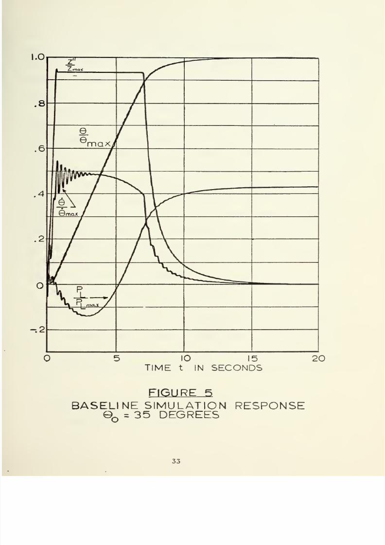
When
the
adapted
baseline
simulation
was
operated under the
potentio-
meter
conditions
listed in
Table
II, with
the
exception of
pots
9
and
10
4
which
were
set
as
previously modified,
the
system behaved
in
the
same
manner as it had during operation
at
the
NSRDC.
Oscillations
identical
to baseline forms were observed in
6
and
P
(Figure
5)
. As
a result
of
Li
this
duplication
of
performance, using
several
different
types
of recording
equipment
that
exhibited
varying
response characteristics, it
appeared
that
the
recording equipment
at
the NSRDC was
not
the
source of the
oscillations.
Further,
since
all errors
in
mathematics
and in
the
settings
of
the
simu-
lator parameters
required
correction
before the
baseline
performance
could
be
successfully duplicated, it
appeared that
the
errors
which
were
found
were the result
of faulty
communication of the
baseline
simulation
to
the
writer,
and
were
not
present
in
the
program
used
to
generate
the
sample
curves.
Apparently,
then,
the
mathematical
models
were
consistent
in
sign
conventions
and
had
been manipulated
correctly
in the
development

7/25/2019 Analysis and Simulation of a Submarine Steering Control System
http://slidepdf.com/reader/full/analysis-and-simulation-of-a-submarine-steering-control-system 68/162
7/25/2019 Analysis and Simulation of a Submarine Steering Control System
http://slidepdf.com/reader/full/analysis-and-simulation-of-a-submarine-steering-control-system 69/162
1.0
.8
.6
.4
.2
-.2
*
Zmooc
-
e
e
maxy
\u~J
f-f
few
Gmax
/
H
>j
max
/
10
15
TIME
t
IN
SECONDS
20
FIGURE 5
BASELINE SIMULATION
RESPONSE
O
=
35
DEGREES

7/25/2019 Analysis and Simulation of a Submarine Steering Control System
http://slidepdf.com/reader/full/analysis-and-simulation-of-a-submarine-steering-control-system 70/162

7/25/2019 Analysis and Simulation of a Submarine Steering Control System
http://slidepdf.com/reader/full/analysis-and-simulation-of-a-submarine-steering-control-system 71/162
of the
analog
board,
the
potentiometers
were
correctly
scaled,
and
the
analog
wiring
was
correct.
Thus,
the
simulation
appeared
to
be
correct
within the
framework
of the fundamental
assumptions involved
in
the
mathe-
matical
formulations;
however,
the
oscillations
were
still
present
in the
output
Two
situations
seemed
to
be
possible.
First,
perhaps the
oscillations
evidenced
in
the
NSRDC
data
were
not representative
of
the behavior
present
in real submarine
steering systems, and
the
simulation
was therefore
in-
adequate.
This situation could
have
occurred
because fundamental
errors
or
omissions
were
made during
the
formulation
of
the
baseline simulation
governing
equations,
say
by the use of
faulty
assumptions regarding
the
significance
of
one or
more
physical
processes
present in
a
steering
system.
The
situation could also
have
occurred
because system materials,
dimensions, and
properties
were improperly represented in the
development
4
of
the numerical values
used
in
the
typical system
simulation,
by the
inclusion of inconsistent units conversions,
unrealistic
dimensions,
or
faulty
physical
materials constants.
Second, perhaps
the
oscillations
appearing in the
NSRDC data
were
representative
of real system behavior,
and the
difficulty
had its origins
in the
harboring
of
an
incorrect knowledge
of the
actual
performance
of
a
ship's
steering
control
system.
No
actual
system
recordings
were
sub-
mitted
with
the baseline
simulation,
and
therefore
no
immediate
comparison
was
possible
between the
simulation
performance
and real
conditions
in the
system.
B. BACKGROUND
INVESTIGATION
1.
Study
of
Currently
Used
Models

7/25/2019 Analysis and Simulation of a Submarine Steering Control System
http://slidepdf.com/reader/full/analysis-and-simulation-of-a-submarine-steering-control-system 72/162

7/25/2019 Analysis and Simulation of a Submarine Steering Control System
http://slidepdf.com/reader/full/analysis-and-simulation-of-a-submarine-steering-control-system 73/162
Assuming
that the oscillations
observed in
the
baseline
simulation
were
not representative
of real steering system
behavior
led
to a back-
ground
investigation
of techniques and
models currently used
in simulating
hydraulic
systems
in
order
to
develop
a
clear
knowledge
of the
fundamental
assumptions
made
during
the development of the baseline
simulation.
This
background
examination consisted
of studies in
the
hydraulic controls
field,
and
communication
with
personnel familiar
with
the simulation and
ship steering
control
systems.
The
search
for currently
used models and
techniques
produced several
results. It
was
found
that
servovalves
were
usually
designed so that
they
were
the
controlling
element
in
hydraulic
systems. However, in the
base-
line simulation, any
error
signal
representing more
than
four degrees
resulted in saturation of
the
control valve,
resulting in
the
servovalve
having
no
variable control over
the
velocity of
the
load,
until
the
error
4
signal
again
fell below
a
value
representing
four degrees.
Thus, the
servovalve
was
virtually
being used
as
an open-shut
valve
much of
the
time. The presence of
deadband and multiple
flow gain
in
the
valve
tended
to reduce the
sensitivity
of
the
valve to
small errors,
and to
increase it for errors
in excess of
four degrees, thus
heightening the
effect.
It was also
noted that if the
expressions
for
the
baseline
simula-
tion were
transformed into
Laplace notation,
and
deadband
and
multiple
flow gain effects
were temporarily
neglected,
the
resultant
expression
would
be
Z(s)
.(
Kl
/
K2
\E(s)
(14)
s+K
3
/K
2

7/25/2019 Analysis and Simulation of a Submarine Steering Control System
http://slidepdf.com/reader/full/analysis-and-simulation-of-a-submarine-steering-control-system 74/162
7/25/2019 Analysis and Simulation of a Submarine Steering Control System
http://slidepdf.com/reader/full/analysis-and-simulation-of-a-submarine-steering-control-system 75/162
N
POOL
VALVE
DYNAMICS
.
u
i/>0
CM*
FEEDBACK
(/)
X
.
LU
O
<
CL
RQUE
MOTOR
DYNAMICS
,
r
o
Ll
1
i
u
»0
u
C\J
O
Is
u
u
«
O
-M
^1
_l
m
—
LO
O
O
h-
—
fc
-)
_
o
u
o
GC
<J
®
UJ
>
_J
<
>
O
>
cc
UJ
Kf)
^
UJ<J
o<
<
CD
fr>£
i
UJ
UJ
IS
h-
UJ
Z>
O
U.O
u_
OLl
q:
n
U
Q_
^
_
O
<
<
Q
^o
^
U0
K
O
LU
^
O
a:
u
_i
Q_
<
OQ
GQ
Q
LU
LU
Ll

7/25/2019 Analysis and Simulation of a Submarine Steering Control System
http://slidepdf.com/reader/full/analysis-and-simulation-of-a-submarine-steering-control-system 76/162
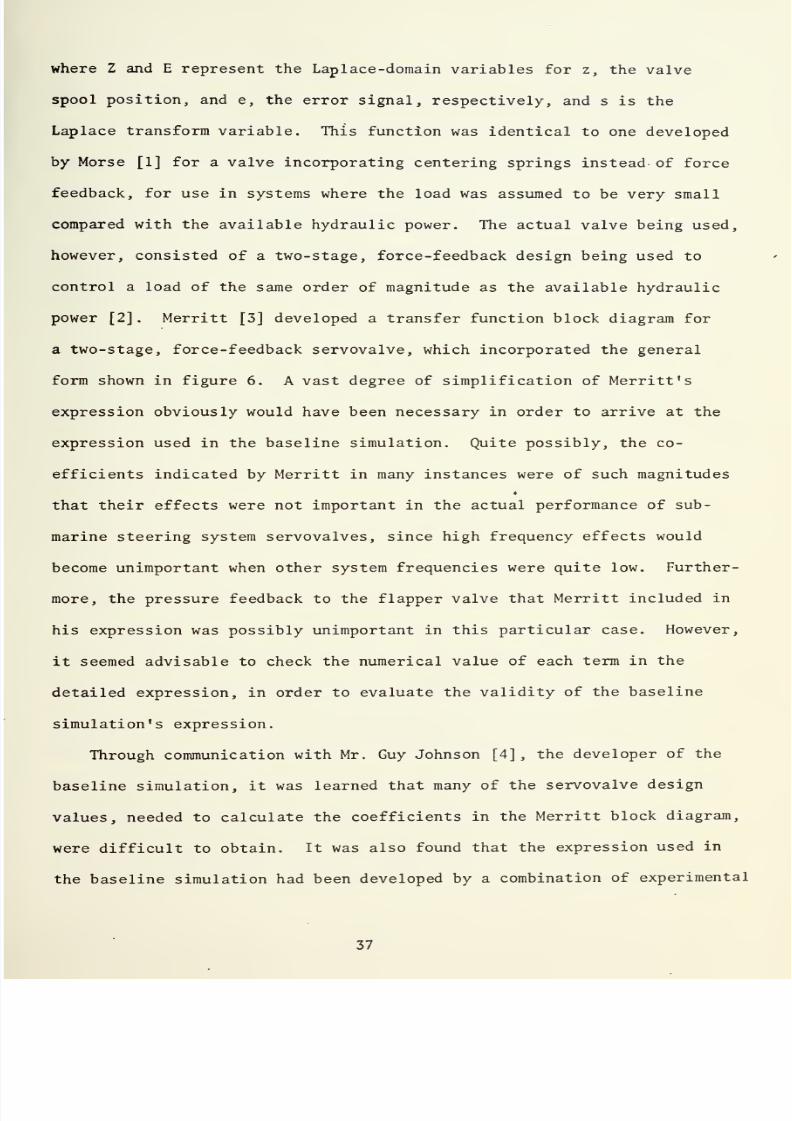
7/25/2019 Analysis and Simulation of a Submarine Steering Control System
http://slidepdf.com/reader/full/analysis-and-simulation-of-a-submarine-steering-control-system 77/162
where
Z
and E
represent
the Laplace
-domain
variables
for
z,
the
valve
spool
position,
and
e, the error signal,
respectively,
and
s
is the
Laplace transform
variable.
This
function
was identical
to one
developed
by Morse
[1]
for
a
valve incorporating centering
springs
instead
of
force
feedback, for
use
in
systems
where the
load was assumed
to be
very
small
compared
with
the available
hydraulic power.
The actual
valve
being
used,
however,
consisted
of a
two-stage,
force-feedback design being
used
to
control
a load
of the
same
order
of magnitude as
the
available
hydraulic
power
[2].
Merritt
[3]
developed
a transfer function block
diagram
for
a
two-stage, force-feedback servovalve, which incorporated
the general
form
shown
in
figure
6.
A
vast degree
of
simplification of Merritt
's
expression
obviously
would
have been necessary
in order
to
arrive at the
expression
used in
the
baseline simulation. Quite possibly,
the
co-
efficients
indicated
by Merritt in
many
instances
were of
such magnitudes
that
their
effects were not
important in
the
actual
performance of sub-
marine steering
system servovalves, since high
frequency
effects
would
become
unimportant
when
other
system
frequencies
were
quite low.
Further-
more,
the
pressure
feedback
to
the flapper
valve that Merritt
included
in
his expression was
possibly
unimportant in this
particular
case.
However,
it
seemed
advisable to
check the
numerical value
of
each term
in
the
detailed expression,
in
order to
evaluate the
validity of the
baseline
simulation's expression.
Through
communication
with Mr.
Guy Johnson
[4],
the
developer
of
the
baseline simulation,
it
was learned
that many
of
the
servovalve
design
values,
needed
to
calculate
the
coefficients
in
the
Merritt
block
diagram,
were
difficult
to
obtain.
It
was
also
found
that
the
expression
used
in
the baseline simulation
had been
developed by a
combination
of
experimental

7/25/2019 Analysis and Simulation of a Submarine Steering Control System
http://slidepdf.com/reader/full/analysis-and-simulation-of-a-submarine-steering-control-system 78/162
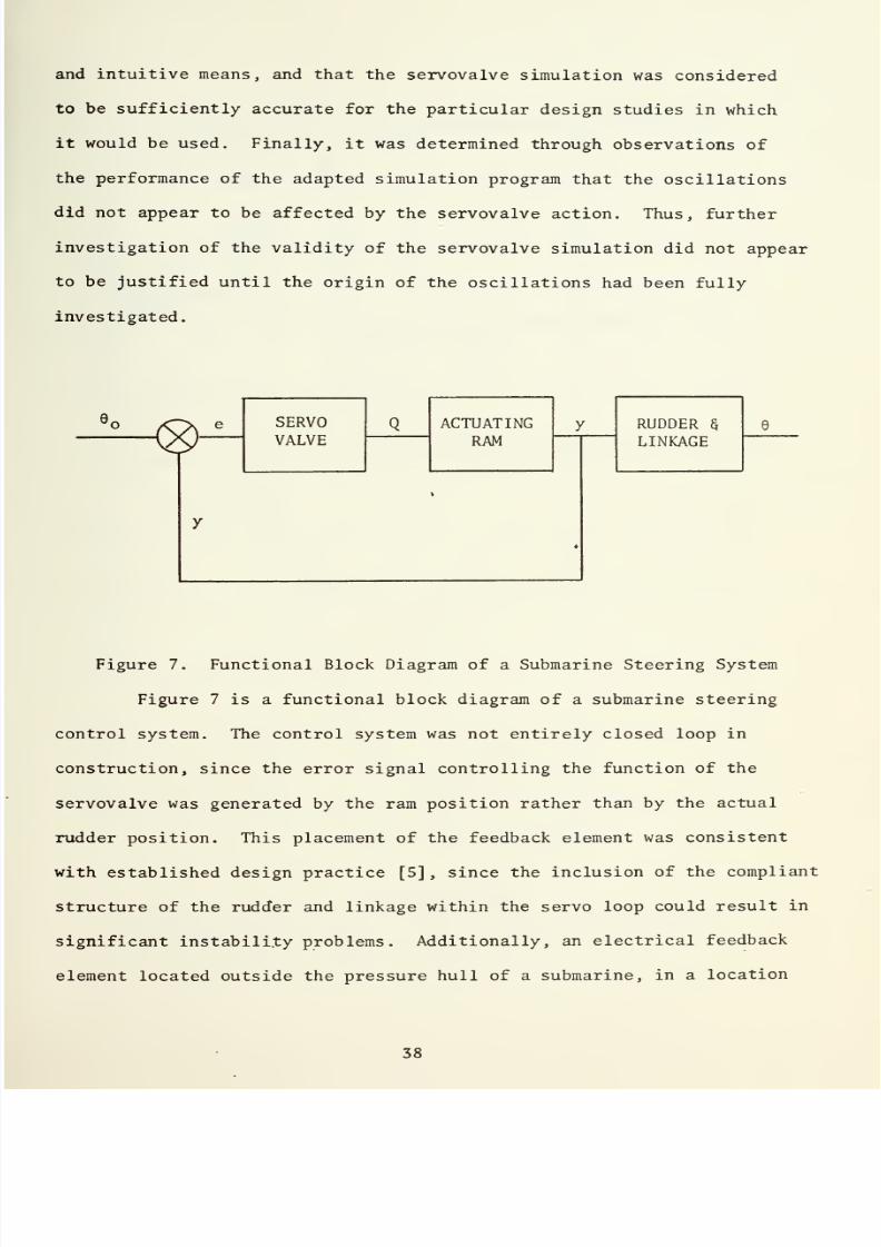
7/25/2019 Analysis and Simulation of a Submarine Steering Control System
http://slidepdf.com/reader/full/analysis-and-simulation-of-a-submarine-steering-control-system 79/162
and
intuitive
means,
and
that
the
servovalve
simulation
was
considered
to
be
sufficiently
accurate
for
the particular
design studies
in
which
it
would
be
used.
Finally,
it
was
determined
through
observations
of
the
performance
of
the
adapted
simulation program
that the
oscillations
did
not
appear to be affected
by
the
servovalve
action.
Thus,
further
investigation of
the
validity
of the servovalve
simulation
did
not appear
to be justified
until
the
origin
of the
oscillations
had been fully
investigated.
SERVO
VALVE
ACTUATING
RAM
y
RUDDER
$
LINKAGE
Figure 7.
Functional
Block Diagram of
a
Submarine Steering System
Figure
7
is a functional
block diagram
of
a submarine
steering
control
system. The
control
system
was
not
entirely
closed
loop
in
construction,
since
the
error signal
controlling the
function
of
the
servovalve was
generated
by the
ram
position rather
than by the
actual
rudder
position.
This placement of the
feedback element
was
consistent
with
established design practice
[5]
,
since
the inclusion
of the
compliant
structure
of the
rudder
and
linkage
within
the
servo
loop
could
result
in
significant
instability
problems
.
Additionally,
an
electrical
feedback
element
located outside
the
pressure
hull of
a submarine,
in a
location

7/25/2019 Analysis and Simulation of a Submarine Steering Control System
http://slidepdf.com/reader/full/analysis-and-simulation-of-a-submarine-steering-control-system 80/162

7/25/2019 Analysis and Simulation of a Submarine Steering Control System
http://slidepdf.com/reader/full/analysis-and-simulation-of-a-submarine-steering-control-system 81/162
I
5
TIME
t
IN
SECONDS
20
FIGURE
8
CURVES
OF
SEVERAL
PARAMETERS
OF
CI
-5000
SIMULATION

7/25/2019 Analysis and Simulation of a Submarine Steering Control System
http://slidepdf.com/reader/full/analysis-and-simulation-of-a-submarine-steering-control-system 82/162

7/25/2019 Analysis and Simulation of a Submarine Steering Control System
http://slidepdf.com/reader/full/analysis-and-simulation-of-a-submarine-steering-control-system 83/162
1.0
.8
.2
-
-.2
z:
1
1
Zmax
1
'
je_ \
/©max
1
e
/
©ITW.X
/
/
/
/
/
4
ovwvvvy
wvvv vvvv
/
10
15
TIME
t
IN
SECONDS
20
FIGURE 9
FRICTIONLESS
LOAD
CONDI
TION,T
p
=
0.

7/25/2019 Analysis and Simulation of a Submarine Steering Control System
http://slidepdf.com/reader/full/analysis-and-simulation-of-a-submarine-steering-control-system 84/162
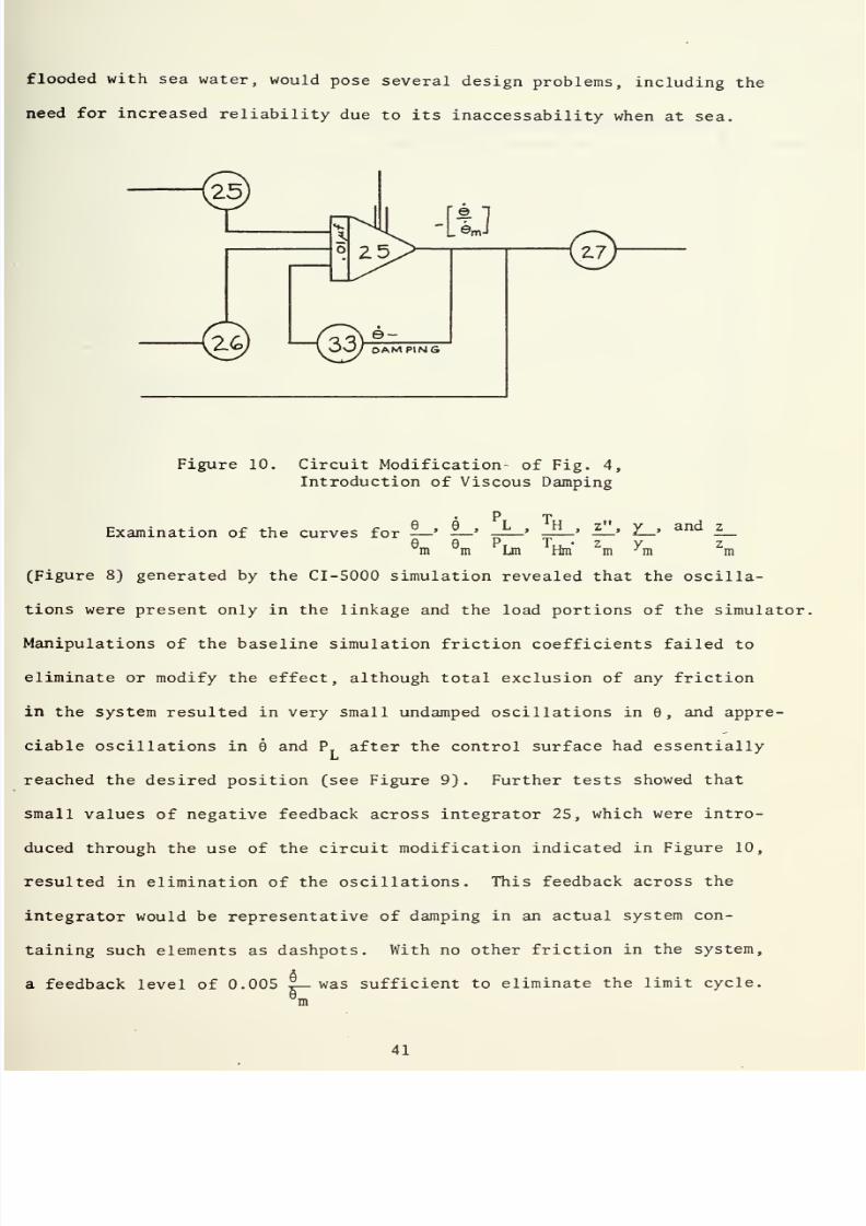
7/25/2019 Analysis and Simulation of a Submarine Steering Control System
http://slidepdf.com/reader/full/analysis-and-simulation-of-a-submarine-steering-control-system 85/162
with
sea
water,
would
pose
several
design
problems,
including
the
for
increased
reliability
due
to its
inaccessability
when
at
sea.
-LU
\^)
U33)
OAMPINK
2-7
Figure
10.
Circuit
Modification
of
Fig.
4,
Introduction
of Viscous
Damping
P
t
Examination
of the
curves for
—
'
—
»
—
'
—
»
—'
?—>
and
—
e
m
e
m
P
Lm
T
Hm*
Z
m
y
m
z
m
8)
generated by
the
CI-5000
simulation
revealed
that
the
oscilla-
were
present only
in
the
linkage and the load portions
of
the
simulator,
of the
baseline
simulation
friction
coefficients failed to
or modify
the effect,
although total exclusion of any friction
the
system resulted
in
very
small
undamped oscillations
in
9,
and
appre-
oscillations in
9
and
P
after
the
control
surface
had essentially
Li
the
desired
position
(see
Figure
9)
.
Further tests
showed
that
values
of
negative
feedback
across integrator
25,
which
were
intro-
uced through
the use of the circuit
modification
indicated in
Figure
10,
in
elimination of
the oscillations.
This
feedback across
the
would be representative
of
damping in an actual
system
con-
such elements as
dashpots.
With no
other
friction
in
the
system,
feedback
level
of
0.005
%—
was
sufficient
to
eliminate the
limit
cycle.
m

7/25/2019 Analysis and Simulation of a Submarine Steering Control System
http://slidepdf.com/reader/full/analysis-and-simulation-of-a-submarine-steering-control-system 86/162

7/25/2019 Analysis and Simulation of a Submarine Steering Control System
http://slidepdf.com/reader/full/analysis-and-simulation-of-a-submarine-steering-control-system 87/162
.00
.8
.4
.2
-.2
»
z
max
/
fa
/
©max
1
l—l
l
1U.A
s/
V \
*
A
i
©maxl
\
4
10
15
TIME
t
I
N
SECONDS
20
FIGURE
VISCOUS
DAMPING
LEVEL
.005*-,
T
F
=0.
max

7/25/2019 Analysis and Simulation of a Submarine Steering Control System
http://slidepdf.com/reader/full/analysis-and-simulation-of-a-submarine-steering-control-system 88/162

7/25/2019 Analysis and Simulation of a Submarine Steering Control System
http://slidepdf.com/reader/full/analysis-and-simulation-of-a-submarine-steering-control-system 89/162
'i
Z_
i Zmax
f
1
Q
.
©
Ci
je
.O
A
-
.
*t
O
..
/ i
/
\
l7
\
'tmx/
\
\
/
*
I
/
O
_
.
c.
IO
15
TIME
t
IN
SECONDS
20
FIGURE
12
e
VISCOUS
DAMPING
LEVEL.I2X
,T
F
=0.
max

7/25/2019 Analysis and Simulation of a Submarine Steering Control System
http://slidepdf.com/reader/full/analysis-and-simulation-of-a-submarine-steering-control-system 90/162
7/25/2019 Analysis and Simulation of a Submarine Steering Control System
http://slidepdf.com/reader/full/analysis-and-simulation-of-a-submarine-steering-control-system 91/162
Furthermore,
feedback
levels
of
0.12
®_
were sufficient to approach
a
Om
critically
damped
condition
in the load
and linkage
simulator.
(See
Figures
11
and
12.)
If
friction
levels
present in the baseline simula-
tion
were
programmed into
the
CI-5000,
approximately
the
same
value of
8
-damping as in the frictionless
configuration was
required
to
produce
critically
damped
behavior, while
the
sustained
limit cycle
was
eventually
eliminated
by the
presence of
the
baseline
friction
itself.
Damping
terms proportional
to 6
were totally absent from
the
base-
line
simulation
equations. Intuitively, however, some
damping
would
be
present in any
system in
which
viscous fluids such
as
sea
water
are
dis-
placed by moving objects,
since work must
be
expended
to
keep objects
moving
at
a
constant
rate, whether
linearly
or rotationally,
through
a
real
fluid.
Thus,
the
neglect
of
damping
in
the
linkage
and rudder portion
of
the
simulation
did
not
appear
to
be
realistic.
t
A
superficial
examina-
tion
of
the
system
did not
reveal any
large
sources
of
damping, or even
sources
which would
provide a
fraction
of
that
needed
to
approach
a
criti-
cally
damped condition
in
the
linkage.
Anticipating that a
lengthy
investigation of
system
damping
would be necessary,
the
writer
identified
this
area
as
requiring
first
priority
for
further
investigation,
and post-
poned
further
analysis
of it.
Correspondence
with
Mr.
Johnson resulted
in
the
writer
receiving
some drawings
of a
671-class
submarine's
steering
control
system
[7].
Examination
of
these
drawings
revealed
that
functional
concepts
of
several
features
of the
design
had
undergone
considerable
alterations
in the
pro-
cess
of
the
development
of
the
idealized
model.
A
compensated
actuator
had
been
assumed
in the
simulation
development;
i.e.,
equal
areas
had
been assumed
on
both
sides
of
the
actuator
ram
(Figure
1)
.
Examination

7/25/2019 Analysis and Simulation of a Submarine Steering Control System
http://slidepdf.com/reader/full/analysis-and-simulation-of-a-submarine-steering-control-system 92/162

7/25/2019 Analysis and Simulation of a Submarine Steering Control System
http://slidepdf.com/reader/full/analysis-and-simulation-of-a-submarine-steering-control-system 93/162
of the
drawings,
however,
and
discussion
with
Mr.
Johnson
revealed
that
the
actuator on a
typical
submarine
was in reality
uncompensated;
i.e.,
unequal areas
were
available
on
opposite sides
of
the
actuating
ram
piston.
The
writer
was informed,
however,
that
the
difference
in
per-
formance
parameters
due
to
the
neglect
of
the unequal
areas was
not
of
major
concern
in
the
overall
reasons for
simulating
the steering
system.
Further
study
of
the
drawings revealed
that
the crosshead
configu-
ration had been
simplified
in such a
manner
that
it
was no
longer
represen-
tative of
the
actual design.
The crosshead,
originally assumed to operate
in a
sleeve
open at both ends, Figure
1,
was
in
reality supported by
a
sleeve open
at only
one
end in most submarine designs,
Figure
13.
The
effect of
this variation in the crosshead
configuration could only be
determined
through
a detailed
knowledge of
the
dimensions, design,
and
clearances
involved
in
an actual
crosshead,
and
these
parameters could
not
be gleaned
from the drawings that the
writer had available.
Further
investigation of
the
crosshead influence
on
the
system seemed to be justi-
fied,
since
the assembly
resembled
a
dashpot in
appearance, and
possibly
was
capable
of providing the source
of
damping
which
seemed
to
be
needed
in
the
system.
Consequently,
a
detailed
analysis
of the
effect
of
a
.
typical crosshead
structure on
steering system
performance
seemed to be
in order,
and was
identified as
an area
for
further
work.
2. Verification
of
Typical
System
Values
Several
nondimensional
coefficients,
load
parameters,
and
properties
had
been
used
to develop
the
simulation,
such as
the
hydraulic
resilience
coefficient,
the
rudder
mass,
and
inherent
materials
properties. Inaccurate
development of
system
numerical
values
could have
contributed
the
system
oscillations.
Attempts
were
made
to
determine the
values
of
many
of
these

7/25/2019 Analysis and Simulation of a Submarine Steering Control System
http://slidepdf.com/reader/full/analysis-and-simulation-of-a-submarine-steering-control-system 94/162
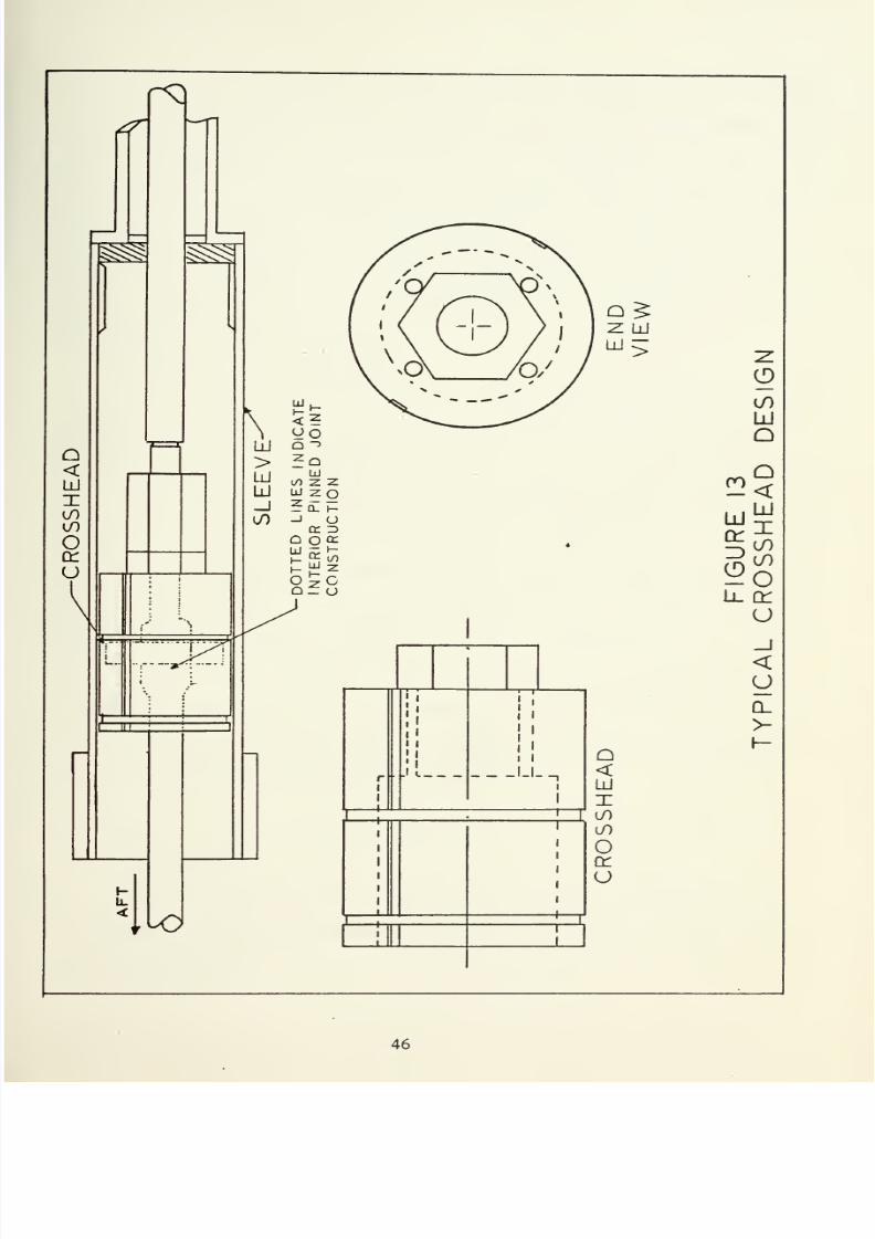
7/25/2019 Analysis and Simulation of a Submarine Steering Control System
http://slidepdf.com/reader/full/analysis-and-simulation-of-a-submarine-steering-control-system 95/162

7/25/2019 Analysis and Simulation of a Submarine Steering Control System
http://slidepdf.com/reader/full/analysis-and-simulation-of-a-submarine-steering-control-system 96/162
7/25/2019 Analysis and Simulation of a Submarine Steering Control System
http://slidepdf.com/reader/full/analysis-and-simulation-of-a-submarine-steering-control-system 97/162
constants
from
basic
principles, but
the
effort
was
thwarted
due
to
a
lack
of
information
regarding
dimensions,
physical
constants,
system construction
details, and
algebraic
expressions
for
any
of
the
nondimensional
constants
Kj through
K
2
-
It became
apparent that
much
time
could be
spent trying to
determine the
validity
of each
derived
constant without having
the
appro-
priate algebraic
expression available
for examination. Therefore,
this
possible
source
of inaccurate
system simulation was identified for further
investigation, and
was set aside.
3.
Actual
System
Performance
Actual system
recordings of
9, 9,
and
P
were
mentioned
by
Mr.
Johnson
as
not demonstrating the oscillations found in the
simulation.
The writer
requested
that
such recordings be forwarded
to
him in
order
to
gain a first-hand knowledge of the
actual
system performance, but
was
unsuccessful
in
obtaining any such recordings.
Without any
more
information
about the actual
system performance
than
the available
qualitative
descrip-
tion
of
the
behavior, no
reasonable
conclusions could be
reached
about
the
actual system
performance. Because
an
accurate
representation
of
a
system
could not be
claimed
until a
favorable
comparison
with accurate
actual
system
performance
could be
accomplished,
it
was
felt
that such a
determina-
tion
of steering
system
performance
would
be
beneficial,
and
the
subject
was
identified
as
requiring
further
investigation.
C.
SUMMARY
OF THE
INITIAL
INVESTIGATION
1.
Conclusions
As
a
result
of
the
duplication
of the
baseline
simulation,
and
subsequent
experiments
performed
with
the
program,
the
following
conclu-
sions were
reached:

7/25/2019 Analysis and Simulation of a Submarine Steering Control System
http://slidepdf.com/reader/full/analysis-and-simulation-of-a-submarine-steering-control-system 98/162

7/25/2019 Analysis and Simulation of a Submarine Steering Control System
http://slidepdf.com/reader/full/analysis-and-simulation-of-a-submarine-steering-control-system 99/162
(1)
The
recording
equipment
at
the NSRDC had
accurately-
recorded the
performance
of
the
simulation,
and
was
not the
source
of the
oscillations.
(2)
The equations
and
potentiometer
settings
were consistent
within the framework
of
the
fundamental
assumptions
involved
in
the
simulation's
mathematical
development.
(3)
The
oscillations
were confined
to
the load portion
of
the
simulator, and did
not appear
to
be sustained
by overall system
instability.
.
a
(4)
A
negative
feedback
level of
0.005
-
—
was sufficient
to
e
m
eliminate
the
limit
cycle oscillation, and 0.12
-r—
achieved
a
critically
e
m
damped
condition, in the load simulation under otherwise
frictionless
conditions. A negative
feedback level of
0.12
®_
was
also
sufficient
to
9m
create a critically damped
condition in
the
load simulator
under
baseline
4
friction conditions.
Studies,
and
communications
with personnel familiar
with
the simula-
tion and
with
actual
submarine
steering
control systems, led to the
following
conclusions:
(1)
The
servovalve
equation
used in the
baseline
simulation
was
not
developed to
completely
model
either
the
type
of
servovalve
used
in
the
real
system
under study, or
the type
of load
which
was present
in
the actual
system.
The net
effect
of the
substitution
of
a
simple
ex-
pression
for a
complicated
one was
not
immediately
determined,
except
that
it
did
not
appear
to
affect
the
system
load
oscillations.
(2}
The
actuator
had
been modeled
in
the
system
simulation
as
a
compensated
ram,
rather
than
being
modeled as
the
uncompensated
actuator used
in
real
systems.
Although
the
effect
of this
simplification

7/25/2019 Analysis and Simulation of a Submarine Steering Control System
http://slidepdf.com/reader/full/analysis-and-simulation-of-a-submarine-steering-control-system 100/162

7/25/2019 Analysis and Simulation of a Submarine Steering Control System
http://slidepdf.com/reader/full/analysis-and-simulation-of-a-submarine-steering-control-system 101/162
on the
system was
unknown, communication with
experienced
personnel
seemed
to indicate
that
the
effect was unimportant.
(3)
The
actual
crosshead design
had
been modeled
in
such a
way
that
damping
effects
possibly present
in
the
component
were
not
taken
into account.
Further
study seemed warranted.
(4)
Viscous
damping
effects in
the
load had been
totally
ignored
in the
development
of the
simulation,
although such effects controlled the
unwanted system oscillations, and
normally
would be present to
some degree
in
any
system
incorporating
the
movement
of structures through real
fluids.
A
search for
viscous damping sources in
the
load was assigned first
priority
for
extensive investigation.
(5)
The
origins
of
many
of
the nondimensional constants used
in the
simulation
were
obscure, and
efforts
to
verify
their correctness
were
unsuccessful, due to the lack of appropriate algebraic expressions,
dimensions,
and
materials constants.
(6)
Actual
documentation
of
real
system
performance
in the
situations being
modeled
appeared to
be
vague
and
incomplete.
Little
information
was
available concerning
the actual response
characteristics
of
submarine
steering
control
systems
to step
inputs.
An
extensive inves-
tigation
of real
system performance
appeared
to
be necessary.

7/25/2019 Analysis and Simulation of a Submarine Steering Control System
http://slidepdf.com/reader/full/analysis-and-simulation-of-a-submarine-steering-control-system 102/162
7/25/2019 Analysis and Simulation of a Submarine Steering Control System
http://slidepdf.com/reader/full/analysis-and-simulation-of-a-submarine-steering-control-system 103/162
III. LOAD
AND
LINKAGE
DAMPING
Of
the
areas
identified in
the
initial
investigation
as requiring
further
research,
only
the
search for sources of
linkage
and
load damping
was
pursued
in the present
investigation. Analysis of the
submarine
system
identified
three locations
where
damping might
possibly
be
present:
the
system's
dynamic
seals
and bearings,
the
crosshead structure, or the
rudder
itself.
No
other components appeared
to
be
designed
in
such
a
manner that
they
could
possibly
produce
an
appreciable quantity of damping.
In
order to
determine
levels
of damping in
the
various components,
detailed information
was
needed concerning dimensions, clearances, materials,
constructions, and lubrication for the linkage parts and
rudder. The writer
was referred
[8]
to
Mr. Leeland Smith
[9]
of
the
Mare Island Naval
Shipyard,
4
who
provided
detailed
drawings
of
the steering
control
system
for
the
SSN
671 class submarine.
A. BEARINGS
AND
DYNAMIC SEALS
The possibility was
considered
that
the expressions
employed
for
the
friction present
in
the
bearings
and
dynamic
seals
(equations
9
and
10)
were not representative
of the actual processes
present
in
the
submarine
system, and that
the
inherent
friction of
the
bearings and
seals
was
better described
as
displaying
viscous behavior.
Keller
[10]
indicated
that compression
packings,
such
as
those
used
at
the
pressure
hull penetration and
the
actuator-piston
rod
interface,
are
normally
lubricated by allowing
very
slight
amounts
of
leakage
past
the
seal.
Examination
of
the SSN-671 drawings revealed
that
the
pressure
hull
packing
was
additionally
lubricated with
grease.
Despite
these
indications

7/25/2019 Analysis and Simulation of a Submarine Steering Control System
http://slidepdf.com/reader/full/analysis-and-simulation-of-a-submarine-steering-control-system 104/162
7/25/2019 Analysis and Simulation of a Submarine Steering Control System
http://slidepdf.com/reader/full/analysis-and-simulation-of-a-submarine-steering-control-system 105/162
that
viscous
effects
could be present in these
seals,
discussions
with
Mr.
Smith,
William
Kendall
[12],
and
Leonard Chase
[12]
of the
Mare
Island
Naval
Shipyard
resulted
in the
writer's
learning
that
friction
in
such
seals
was
best
approximated
as
sliding friction, since
friction
loads
were
normally
observed
to
be fairly
independent of actuator rod
velocity, due
to
the velocities
and
allowable leakage
rates present
in
the system.
Thus,
the
baseline model of
seal
friction appeared
to be
justified.
Study
of the rudder bearings seemed
to
support
the use of the baseline
simulation's
bearing
friction expressions.
The large
rudder
weight,
com-
bined
with
hydrodynamic
loads,
small rates
of
rotation
present
in
the
rudder stock, and
the
ill-defined lubricating qualities of sea water,
resulted
in
enough
analytical
uncertainties being present to
discourage
any attempt
to
model
such bearings
as either
slipper-type
or
journal-type
surfaces.
Again, the
baseline
simulation expression
seemed
to
provide
a
*
bearing
surface
description
that
probably
was
as
accurate in
magnitude
and
parameter
dependence
as
any
other expression
that
could be
analytically
developed
using known conditions and existing lubrication
theory.
Experi-
mental
and
analytical
work of
a scale
beyond
the scope
of this
project
could
prove
useful
in
future
design work
involving
bearings and
seals of
the
types
present
in the submarine
system.
B. CROSSHEAD
1.
General
Description
Examination of
the
SSN-671
drawings, and
discussions
with
Mssrs.
Smith, Kendall,
and
Chase
concerning
general
construction
details
of
crossheads,
revealed
that,
as
a rule,
crossheads
somewhat
resembled
dash-
pots
in
construction,
due
to
their piston-in
sleeve
arrangements,
and
their
free-flooded
nature.
Provisions were
normally
made
in
the
construction
of

7/25/2019 Analysis and Simulation of a Submarine Steering Control System
http://slidepdf.com/reader/full/analysis-and-simulation-of-a-submarine-steering-control-system 106/162

7/25/2019 Analysis and Simulation of a Submarine Steering Control System
http://slidepdf.com/reader/full/analysis-and-simulation-of-a-submarine-steering-control-system 107/162
crossheads
to
eliminate any
possible damping
effect
by
the
drilling
of
large
holes
through the piston
portion
of
the
structure.
Because
damping
sources
were
being
sought,
the writer decided
to
analyze
the
crosshead
in
order
to
determine
what
damping
effects, if
any,
were
present.
Figure
13
shows a
crosshead design
based
on information
taken
from
the
SSN-671
drawings.
The
crosshead
consists
of
a
partially
bored
out
cylinder
19
inches
in
length,
with
a
diameter of 11.986
inches,
and four
one-inch I.D., eight-inch in
length
holes
axially bored
through the
solid
head of the piston. This piston
rides
in a
twelve-inch I.D.
tube,
typically
sealed
along
its
length except
at
the rear
end,
which
is
open
to
allow
the
passage
and free
rotation of
the link
connecting the actuator shaft
ex-
tension and
the
rudder
tiller. The
piston
incorporates several lock-
preventing 0.75
in. X
0.125
in.
circumferential grooves, and
two 0.125 in.
X
0.5
in.
axial slots
along the
outside radius. As
a
result
of
the
radial
clearance between
the
piston and
the sleeve, the slots,
and the
holes
in
the
crosshead,
the entire sleeve
is
free flooded, and flow
of
sea
water
past
the
crosshead must take
place as
it
is
moved
in and
out
of
the
sleeve.
2. Assumptions
In approximating
the
behavior
of the
flow
past
the
crosshead
and
the viscous
drag
associated
with
that
flow,
it was
assumed
that
the fluid
velocities through
the
holes, slots,
and radial
clearance
of the
crosshead
were considerably
greater than
the
motion
of the
piston
relative to
the
sleeve,
thereby
implying
the
existence of
fixed
orifices
of irregular
shape. Laminar
flow
was also
assumed.
3.
Equations
a.
Eccentric Piston
in a Sleeve

7/25/2019 Analysis and Simulation of a Submarine Steering Control System
http://slidepdf.com/reader/full/analysis-and-simulation-of-a-submarine-steering-control-system 108/162

7/25/2019 Analysis and Simulation of a Submarine Steering Control System
http://slidepdf.com/reader/full/analysis-and-simulation-of-a-submarine-steering-control-system 109/162
For an annulus formed
by
a
solid eccentric
cylinder
in a
sleeve
with no
relative movement involved,
the
flow
rate
can be expressed
as
[13]
-rrrc*
Qc
6yl
I
(IV
K
(15)
where
r
is the
radius
of
the sleeve,
y
is the
absolute viscosity
of the
fluid,
1
is
the
length of the tube,
e
is the eccentricity of the
piston
with
respect to the center
of
the sleeve,
and (P^-P2)
is the
pressure
drop across
the length of the
tube.
b.
Laminar Flow
Through Rectangular
Passages
For
the
slots
[13]
3
Q.
=
wh
12yl
, 192h
.
.
ttw
1
.
tanh
^
IT
W
(16)
where
w
is
the width
of
the
slot,
h
is
the
depth,
and
all
other
symbols
retain
their
previous
meanings.
«
c.
Flow Through
Short-Tube Orifices
Merritt
[14]
,
combining
the
work
of
Langhaar
[15]
,
Kreith
[16]
and
Shapiro
[17]
,
developed
an expression for
the
flow rate
0~
through
short
tube orifices
=
C
A
i
1/2
(|)(V
p
J
C
=
[1.5+13.74(5^)
]
2
r
1
~
1/2
[2.28+64
(^
-V;
DRe
DRe
>
50
<
50
(17)
(18)
where
C is
the
loss coefficient,
p
is the fluid
density,
D
is the
hole
diameter, Re
is the
Reynolds Number
based
on the mean
velocity
of
the
flow
in the tube
and the
hole
diameter, and
all
other
variables
retain
their
previous
meanings.
If
equations
15,
16,
and
17
are
manipulated

7/25/2019 Analysis and Simulation of a Submarine Steering Control System
http://slidepdf.com/reader/full/analysis-and-simulation-of-a-submarine-steering-control-system 110/162

7/25/2019 Analysis and Simulation of a Submarine Steering Control System
http://slidepdf.com/reader/full/analysis-and-simulation-of-a-submarine-steering-control-system 111/162
the pressure
drop
P-i-P?
can De
expressed
as a function
of the
fl
CL,
the kinematic viscosity
v,
D, and
p:
ow
P
r
P
2
=
8p
b
D
J
1.5+6.87/^1
Of
12.
5^1
X)
]
2.28+
16Trvl
C^12.5Trvl
f
a
total mass
balance
is
made across the crosshead,
it
is
found
that
AcH
Y
=
m
+
NQ
S
+
Q
c
(20)
A^j, is the cross -sectional area
of
the
crosshead,
M
is the
number
of
in the crosshead, and
N is
the number
of slots.
The
force caused
by the
pressure
difference across the
crosshead
be
expressed
as an
equivalent
torque
T
r
„
at
the
rudder
pivot, by
multi-
the crosshead
force
F
=
V
H
(P
1
-P
2
)
by the
length
L
of
the tiller
T
CH
=
A
CH
L
(P
r
P
2)
'
^
14 shows
curves
of Tqj
versus
y
generated through the
solution
of
(18)
-(20)
using
the
previously
listed crosshead
dimensions,
p
to
64
lbm/ft
,
and
v
equal
to
1.41
X
10
D
ft^/sec (water
at
50 degrees
,
for
various sizes
of
piston
holes,
assuming
four
holes and
two slots,
an eccentric
piston
in
the sleeve.
To
generate the
curves,
equations
(18)
and
(19)
were
solved for P-.-P2
as
a
function
of
Q
n
-
Then
Q
and (L.
calculated,
and
appropriate multiples
of
Q
,
Qc,
and (L,
were
used
in
ccordance
with
equation
(20)
to
produce
y.
Equation
(21)
was then
used
to
T
r
„
For
any crosshead incorporating
four
holes any
larger
than
0.1
inches in
diameter,
it
was
found
that zero pressure
differential
existed.
the
diameter
of
the
holes
was decreased,
with
the
dimensions
and
number

7/25/2019 Analysis and Simulation of a Submarine Steering Control System
http://slidepdf.com/reader/full/analysis-and-simulation-of-a-submarine-steering-control-system 112/162

7/25/2019 Analysis and Simulation of a Submarine Steering Control System
http://slidepdf.com/reader/full/analysis-and-simulation-of-a-submarine-steering-control-system 113/162
4.0
X
c
•
^»^
i
3.0
2.0
1.0
U
N
O
HOLES
/
/A
0,075
D=0.1
ft
\
.2
.4
.8
1.0
'e
max
FIGURE
14
CROSSHEAD
TORQUE
FOR
VARIOUS HOLE
SIZES

7/25/2019 Analysis and Simulation of a Submarine Steering Control System
http://slidepdf.com/reader/full/analysis-and-simulation-of-a-submarine-steering-control-system 114/162

7/25/2019 Analysis and Simulation of a Submarine Steering Control System
http://slidepdf.com/reader/full/analysis-and-simulation-of-a-submarine-steering-control-system 115/162
of
slots
and the parameters
for
the annulus
remaining
constant,
a
pressure
differential
began
to
exist
across
the
structure.
Finally,
as
the
holes
were
eliminated,
(P-i-P?)
approached
levels
sufficient
to
create
significant
values of Tq,. For the values of
the
zero-holes curve
used in Figure
14,
Tqj
could
be
expressed as
t
ch
=
7
-
48X1
°
3
y
C
22
)
y
e
or,
since
-
*\i
n
—
y
6
•'m
max
T
CH
=
(7.48X10
3
ymax)
(f^)
(23)
If
the above
equations were
scaled for introduction
into
the
simulation, potentiometer 33
would
be set
according
to
the
expression
7.48X10
3
ymax
r9/n
a__
=
:
U*J
33
100
16
max
For
I
=
9100,
and
y
max
=
3 inches
per
second,
4
a
33
=
.00412.
Since
this
value
of
the
potentiometer
represented the maximum
available
Tp„, it
was
seen
that
the
actual effect of the
crosshead
on the
system
damping was
very small.
In
fact,
using
one-inch
diameter holes
would
make
the crosshead
damping essentially
zero.
However, since a
feedback
level of
Q
.005
j—
was
previously found
to
be sufficient to
eliminate
limit
cycles
in
e
m
the
frictionless
system
simulation,
.00412
__
could
assist
other
small
sources
in
the
damping
of
the
oscillations
in
the
baseline
simulation.
Al-
though
the
results
of
the
investigation
of
the
crosshead
damping
were
less
spectacular
than
had been
desired
originally,
since
the
6-
feedback
sufficient
to create
a
critically
damped condition in
the
load
had
not
been
justified,
the
author
felt
that the identification
of
a
small
source
of
damping
had

7/25/2019 Analysis and Simulation of a Submarine Steering Control System
http://slidepdf.com/reader/full/analysis-and-simulation-of-a-submarine-steering-control-system 116/162
7/25/2019 Analysis and Simulation of a Submarine Steering Control System
http://slidepdf.com/reader/full/analysis-and-simulation-of-a-submarine-steering-control-system 117/162
achieved,
that identification possibly
proving to be
of some
worth
in
design
work
if
a small
amount
of damping
somehow
proved necessary.
Some argument
could
have
been
made
that
further
modification
create
more
damping.
However,
for
this
to
be
done,
the
system would
to be
sealed
at
both
ends, due to
the
approach
of P
2
t0
the vapor
of
water
in the contained volume
when the crosshead
was moving
of
the
tube.
Of
course,
the open
end
of
the
crosshead
sleeve
was not
of being
closed,
due
to
the primary function
of
the
crosshead,
was
to provide
a
portion of
a
slider-crank
mechanism.
The
previously
levels of
Tq,
thus appeared
to
be
the
maximum practicable.
damping
could
be generated, if needed, through the use of
a
dashpot in parallel
with
the actuating linkage.
However,
such
a
was not apparently needed, as was
shown
through
investigation of
inherent
damping
of
the rudder.
*
.
RUDDER
The description of
the
moments involved
in
the rotation
of
a
rudder
its pivot,
while
moving through
a
fluid,
would
in
general
include
involving
the zero,
first,
and second-order
derivatives of
rudder
with respect
to
time.
That
is,
if
a
moment
balance were
written
for
rotating
rudder,
the
equation could
in general take
the
following
form:
M
=
f^e')
+
f
2
(9)
+
f
3
(6)
(25)
f
,
f~,
and f would be functions
of some
yet-to-be-determined
form.
1
*
«j
consideration
of the natures
of
f. and f
revealed
that
expressions
these
two
functions were present
in
the
baseline
simulation.
If
f
2
=
=
0,
the general
expression
is
reduced
to
M
=
f
1
(V)
(26)

7/25/2019 Analysis and Simulation of a Submarine Steering Control System
http://slidepdf.com/reader/full/analysis-and-simulation-of-a-submarine-steering-control-system 118/162
7/25/2019 Analysis and Simulation of a Submarine Steering Control System
http://slidepdf.com/reader/full/analysis-and-simulation-of-a-submarine-steering-control-system 119/162
f.
is
recognized as being of
the
form
fj
=
ie
(27)
I
is the
polar
moment of inertia of
the
rudder and
its fluid
added
If f-,=f2=0,
f-r
is
recognized
as
the sum
of
all
6
-
dependent
in the rudder,
including
the
hydrodynamic
torque caused
by
the
lift
and the
difference between the location
of
the
rudder's
pivot
its
center
of
pressure,
and the -
dependent
portion
of
the
system
The
function
f
(9)
was
assumed
equal to zero in the
baseline simulation;
is
,
no
q
-
dependent
effects
were included in
the
rudder's equation
of
(Eqn.
8).
The
validity
of
this
assumption was
examined
in
the final
of
the investigation
of
load
and
linkage damping.
1.
Existence
of
a
Non-Zero
Function
f
2
(
e
)
Initial considerations of
the problem
involved
the search for any
that
a
non-zero
function
f
2
(8)
even existed.
Intuitively, such
relation should exist in some magnitude,
at
least under
a
condition
where
rudder was
subjected
to
a
constant turning rate while immersed
in
a
viscous
fluid,
since
power
would necessarily be
expended
to
keep
a
structure moving under
these conditions,
thus
resulting
in
some
level
torque
being
applied
to
the rudder shaft. This applied
torque,
then,
by
Eqn.
(25)
be
equal to
f
2
(e),
and
therefore f
2
could not
be
identically
Another indication of
the
existence of
a
non-zero
f
2
was
provided
Landweber
[18],
who
indicated
that forces
on
lifting
surfaces
in
unsteady
were
due
to
a
combination
of inertia
effects
and
circulation,
and
a
transient
variation did
exist in the
circulation
around
a
thin air-
impulsively
given
an
angle
of
attack
a,
causing
a
transient
behavior

7/25/2019 Analysis and Simulation of a Submarine Steering Control System
http://slidepdf.com/reader/full/analysis-and-simulation-of-a-submarine-steering-control-system 120/162

7/25/2019 Analysis and Simulation of a Submarine Steering Control System
http://slidepdf.com/reader/full/analysis-and-simulation-of-a-submarine-steering-control-system 121/162
the
lift
coefficient of
such
a
surface.
Additionally,
Theodorsen
[19]
the
forces on a
foil
undergoing harmonic
oscillations in
connection
studies
of control surface
flutter and
aerodynamic
instability,
and
that the
actual
lift
coefficient
was
related
to a
quasi-steady
lift
corresponding to
the
instantaneous angle
of attack of the foil,
time. Thus,
the existence
of
a
non-zero function
f
2
(9),
while not
by
the above
references, was
at
least
shown
to
be plausible.
The
therefore attempted
to
locate
any
work
that
had
been done in the
nalysis of
the
forces
and
turning
moments on airfoils
or
rudders
subjected
constant turning
rate.
2. Damping
in
a Rudder
Immersed
in
a
Stationary
Fluid
No
references
were
found
describing the resisting torque developed
a
rudder subjected to
a
constant rate
of
rotation
while
immersed
in
a
fluid.
Accordingly, the writer
attempted
to
approximate the
drag
could be expected, using
elementary
concepts
and
simplifying
Figure 15. Rudder
Construction
Assumed
For
Stationary Rudder
Torque
Calculation

7/25/2019 Analysis and Simulation of a Submarine Steering Control System
http://slidepdf.com/reader/full/analysis-and-simulation-of-a-submarine-steering-control-system 122/162

7/25/2019 Analysis and Simulation of a Submarine Steering Control System
http://slidepdf.com/reader/full/analysis-and-simulation-of-a-submarine-steering-control-system 123/162
The
rudder was
approximated by
a
series
of very small
flat plates,
to
be separated
from each other so that the
flow
could
move around
plates
(Figure
15)
.
For
a
flat
plate
placed in
a
stream flowing
perpen-
to
the
plane
of
the
plate,
the
drag force
F
n
can
be
expressed
as
F
D
=C
d(
£
1-)
A
p
(
28
)
C
n
in this
case is
the
drag
coefficient,
p
is the density,
A
is
the
D
p
of the
small
plate, and
the
velocity
V
is related to the
radius
r
and
angular rate of rotation 6 by
V
=
r§.
Thus,
for
a
differential
area
p
,
pr
2
9
2
iF
D
C
d
I
~2~
)
dAp
the
area is
assumed to
be
equal
to the span of
the rudder S times the
distance dr,dA^
=
Sdr, then
dF
D
=
C
D
£
-r
L
-
I
incremental
torque dT^
caused
by
F~
developed at
a
distance
r from
the
point
of
the
rudder
would be
dT
R
=
S
(
T
)
Sr3d
(29)
for
the
portion of
the plate
from r
=
to
r
=
r
,
CpSr
4
a
flat
plate
in
a
normal
stream with
a
large
S/dr
ratio,
CL
is
1.95
[20].
For the
two
rudders
of
a
typical
submarine,
following
physical
parameters are representative:

7/25/2019 Analysis and Simulation of a Submarine Steering Control System
http://slidepdf.com/reader/full/analysis-and-simulation-of-a-submarine-steering-control-system 124/162
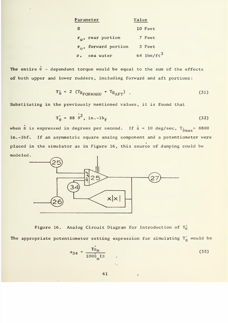
7/25/2019 Analysis and Simulation of a Submarine Steering Control System
http://slidepdf.com/reader/full/analysis-and-simulation-of-a-submarine-steering-control-system 125/162
Parameter
r
,
rear
portion
Value
10 Feet
7 Feet
r
,
forward
portion
3
Feet
p,
sea water
64
lbm/ff
The entire
6
-
dependent
torque
would
be
equal
to
the sum
of
the
effects
of
both upper
and
lower rudders,
including forward
and aft
portions:
T
e
=
2 (t
R
F
orward
+
Tr
aft
}
•
Substituting in the previously
mentioned
values,
it is found that
(31)
Tq
=
88
6
,
in.-lb
f
(32)
when
6
is
expressed
in
degrees per
second. If
= 10 deg/sec, T-
=
8800
in.-lbf.
If
an
asymmetric
square analog
component and
a
potentiometer
were
4
placed
in
the
simulator as in Figure
16,
this
source
of damping
could
be
modeled.
Figure
16.
Analog Circuit
Diagram
for
Introduction
of Tq
The
appropriate
potentiometer setting expression
for
simulating
T*
would
be
Te
l
34
m
1006
IB
m
(33)

7/25/2019 Analysis and Simulation of a Submarine Steering Control System
http://slidepdf.com/reader/full/analysis-and-simulation-of-a-submarine-steering-control-system 126/162

7/25/2019 Analysis and Simulation of a Submarine Steering Control System
http://slidepdf.com/reader/full/analysis-and-simulation-of-a-submarine-steering-control-system 127/162
Substituting
numerical
values,
a
34
=
.968
X
10
3
.
(34)
Thus, the
initial
estimate
of
available rudder
drag
at
zero
velocity
indicated
negligible
amounts
of
damping were
present
in the
rudder turned
at
a
constant
rate
in
a
stationary
fluid. The
writer
felt
that the
results were
incon-
clusive,
however,
since
the assumptions
which
were
made
in the
calculation
of T
R
were
very
rough indeed. The rudder was not formed of many small
strips
with spaces
between
them;
nor was
the
flow
as simple as that described
by the
model.
Such
a
complicated
flow
as would be present
along the
surface of
a
large flat
plate rotating
in
a
quiescent fluid
required
much more
analysis
and study than- the writer afforded it. He
therefore
concluded that future
studies
in
this area were
necessary,
and set
aside consideration of
the
stationary rudder
case.
3. Damping in
a
Rudder Immersed
in
a
Moving
Stream
A
literature search revealed
that
an analysis
had
been made
of
the
torque
behavior
of
a
turning rudder
immersed
in
a
moving
stream.
Okada
[21]
published
a
paper
dealing with
the
effect, which was
subsequently
expanded
by Kennard
and
Leibowitz
[22]
in
their
studies of rudder
performance
as
affected
by
ship turning,
steady
change
of
rudder
angle, and
propel
lor race.
Kennard and Leibowitz
[23]
noted
that
the twisting
moment
observed
on
a
rudder
shaft while the
rudder
is
being turned may
differ
considerably
from
its
value
when
the
rudder
is stationary.
They
went on
to
explain
that
this
effect was due
to
circulatory motions around the
foil
caused
by
viscosity
effects of
the
water,
which subsequently generate vortex
sheets
in the
water
downstream
from the
rudder's
trailing
edge, and
cause
moment-
modifying
variations in the pressure
distribution
over
the
rudder's
surface.
7/25/2019 Analysis and Simulation of a Submarine Steering Control System
http://slidepdf.com/reader/full/analysis-and-simulation-of-a-submarine-steering-control-system 128/162

7/25/2019 Analysis and Simulation of a Submarine Steering Control System
http://slidepdf.com/reader/full/analysis-and-simulation-of-a-submarine-steering-control-system 129/162
Variations
from steady state
twisting
moments by
as
much
as
thirty
percent
were
mentioned
as
being observed
in rudders
turning
at constant
rates
The mathematical
difficulties
associated with the problem
were
simplified by
several
approximations.
The
rudder
was
replaced
by
the
flat
plate,
shown
in Figure
17,
of
uniform
chord
C and infinite vertical
span.
The
water
was
assumed to approach the
plate
at
a
uniform rate and
at
an
angle
of
attack
a;
its velocity
was
denoted by U.
The rudder twisting
per unit
span was
identified
as
M„,
and was
assumed
positive
when
operating in
a
direction to
decrease
a.
The
pivot point
of the
plate
was
identified
as
H,
and
was
located
at
a
distance hC
from
the leading
edge,
h
being assigned some numerical value
between
0.25 and
0.50. The
rudder
turning
rate
was assumed positive for
increasing
angles
of
a.
Figure
17. Flat Plate
Approximation
to
a
Rudder
Turning
at
Constant Rate
Ml,,
the
twisting
moment per
unit span,
was
placed
in
nondimensional
form
by dividing it by
(1/2)
C^U
,
to form
the
dimensionless
moment
coefficient
CL_j.
An expression for
(1^
was
then derived,
with
C
being
represented
as
the
sum of
a
quasi-stationary
part
C^,
n
,
and
a
-
dependent
part,
AC^.
Thus,
SlH
=
C
MH0
+
AC
MH
(35)

7/25/2019 Analysis and Simulation of a Submarine Steering Control System
http://slidepdf.com/reader/full/analysis-and-simulation-of-a-submarine-steering-control-system 130/162
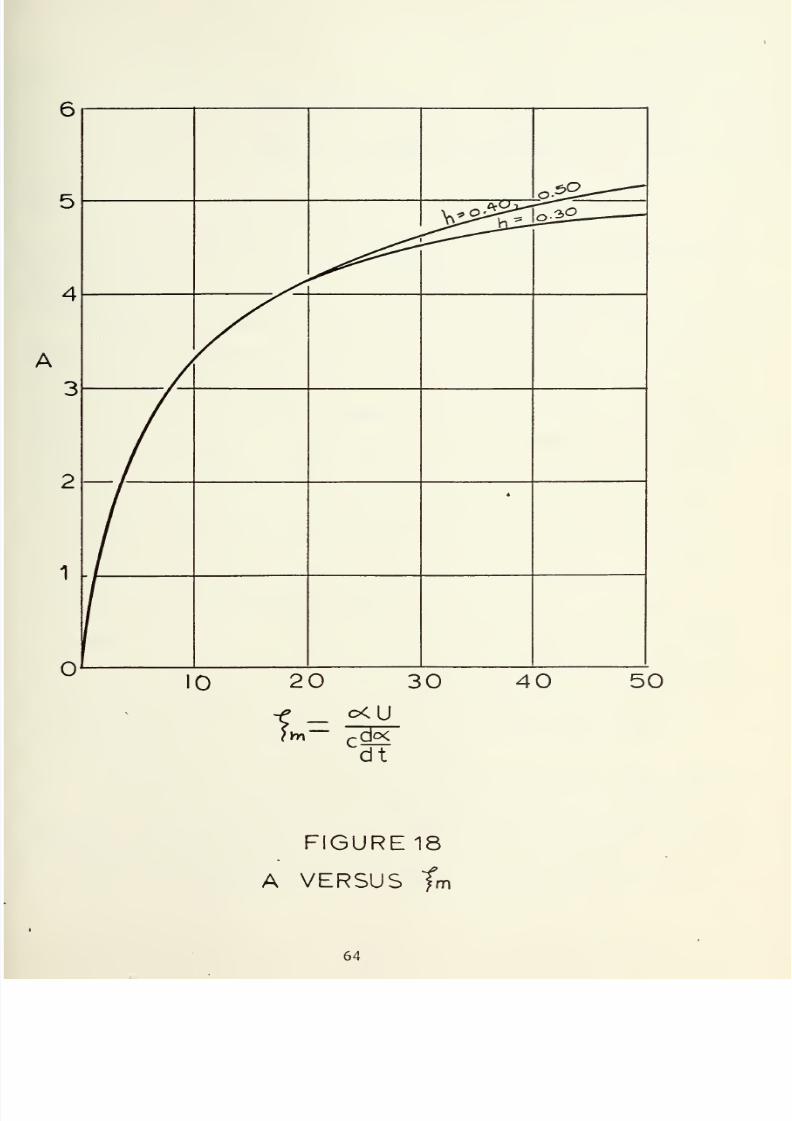
7/25/2019 Analysis and Simulation of a Submarine Steering Control System
http://slidepdf.com/reader/full/analysis-and-simulation-of-a-submarine-steering-control-system 131/162
O.SO--—
^^^
o^£_
*
2
—
20
30
c<U
t-=
d<X
dt
40 50
FIGURE18
A VERSUS
fm

7/25/2019 Analysis and Simulation of a Submarine Steering Control System
http://slidepdf.com/reader/full/analysis-and-simulation-of-a-submarine-steering-control-system 132/162

7/25/2019 Analysis and Simulation of a Submarine Steering Control System
http://slidepdf.com/reader/full/analysis-and-simulation-of-a-submarine-steering-control-system 133/162
where
Cj^q
=
(4
-h)
2
tt«
(36)
ACmh
-
(*0B
r(|-h)(l-2h)-(I-h)A]
(37)
and
C da
-^
U
dt
and
A is
a
function of
£i
and
a
.
The effect
of A
is to
increase
the
value
of
ACwu
as a increases, as is
shown in
Figure
18.
Kennard and
Leibowitz
reported that
the
expression for
C
was
not
entirely
correct, due to
the
neglect of
a nonlinear
effect
in
its
develop-
ment.
That
nonlinear
effect concerns the
aft
movement
of
the
center of
pressure
in
a rudder
as
a
is increased, which causes
a
change in the sign
of
Cwu^
with increased a. Also,
they
indicated
that
values
for
ACwu
obtained
from model tests suggested
that
the
calculated values of
AC^ were
somewhat
too
high,
although the scatter
of
the experimental
data in
the
tests
was
considerable.
They further
concluded
that
the
general
trends resulting
from
turning
real
rudders
in
water
were modeled in
their theory,
although
values
for
AC.
were somewhat
too
high, such
as
a
calculated increase
in
one case
where
h
=
0.3 of
roughly 40
percent, where
in
practice
the
increase
due
to
AC
ranged
from 15
to
40
percent. It was
suggested
that
tests with
larger
rudders
would be worthwhile, and
that refinement
of
the
analysis
was
needed, expecially
in including the effects
of
finite rudder
spans.
4. Application
to
the Simulation
Problem
The analysis
just described
seemed to be
applicable to
the
simulation
problem.
Although
the
expression
for
C.^,.,
was
apparently unrealistic,
the
development
ofAC
was apparently
useful in
predicting the
effect
of
rudder
turning
on the
observed
moments
on
a
rudder,
although
calculated
values

7/25/2019 Analysis and Simulation of a Submarine Steering Control System
http://slidepdf.com/reader/full/analysis-and-simulation-of-a-submarine-steering-control-system 134/162

7/25/2019 Analysis and Simulation of a Submarine Steering Control System
http://slidepdf.com/reader/full/analysis-and-simulation-of-a-submarine-steering-control-system 135/162
seemed
to be somewhat
higher than
values
which were
experimentally
obtained.
In
spite of its
inherent shortcomings,
incorporation
of
this
modeling
of
the
effect
of rudder
turning
rate
on the
observed
twisting moment
seemed
justified
in light
of
the
reported
magnitudes
of
change
in
twisting
moment
observed in practice.
In
order to
apply
the above analysis
to
the
simulation,
several
assumptions were made.
It
was assumed that
a
was
identical to
8
j
that is,
that the fluid flowed parallel
to
centerline
of
the
submarine.
Analysis of
rawings of
the SSN-671
submarine
rudder revealed
that
h
was
approximately
equal
to
0.28;
in
order
to compensate for
the
reported high
nature
of
the
calculated
ACw
H
,
and
to
simplify
calculations,
h'was assumed to
be
1/4,
thus
eliminating
dependence
on
A.
Also,
the sign convention
of
M„
was
eversed
to
conform
to
the simulation's convention. The
above
assumptions
hen
used in the expression for AC resulted
in
*
iC
MH=-^
UHl)
•
(38)
Re-dimensionalizing
to form
AM„,
the
change
in
twisting moment per
unit
span due
to
6,
and
then multiplying by the span
length
S,
resulted
in the
expression
AM
H
S
=
-
j
pC
3
SV9
.
(39)
For
a SSN-671
rudder,
the
average value
of
C
is about
10
feet,
and
S
is
also
about
10
feet.
In
a
typical
submarine
V
can vary
from zero
to
in
excess
of 35
ft/sec,
and 6 was assumed
in the baseline
simulation to
vary
from
zero
to 10 degrees/sec.
Assuming
p
=
64
lbm/ft
,
the
maximum
value
of
the twisting
moment,
(AM„S)
max
based on
Vo
=
35
ft/sec,
would
be
(AMoS)
=
5.72
X
10
5
in-lbf.
(40)
tl
max

7/25/2019 Analysis and Simulation of a Submarine Steering Control System
http://slidepdf.com/reader/full/analysis-and-simulation-of-a-submarine-steering-control-system 136/162
7/25/2019 Analysis and Simulation of a Submarine Steering Control System
http://slidepdf.com/reader/full/analysis-and-simulation-of-a-submarine-steering-control-system 137/162
a
submarine has
two
rudders,
of
approximately the
same
design.
he total
twisting
moment
available
would
therefore
be
twice the
above
6
or
1.144 X 10 in-lbf. An expression
for
AM
H
S/(AM
U
S) would be
n
M
max
AM
H
S
_
/
V
(AMoS)
I
v
/
I
J
(41)
v
H
-'max
\
u
/
\
max
/
H
S)
is
dependent only
on
e
for
a
given
value of
V,
and
therefore
be simulated
as
damping across integrator
25
as
in
Figure 10. The
propriate expression
for the
potentiometer
setting
a.$$
would
be
a
33
C
A
%
s
)maxCV/V
)
(42)
16
ffiax
d00)B
V
=
V
Q
,
and
the
conditions otherwise assumed
above, since V appeared to
set equal
to
V for
the
other
V
-
dependent parameters
in
the
baseline
a^^
=
0.1259.
A
level of
0.12-r
feedback
was
previously
found
m
be sufficient
to approach
a critically
damped behavior
of
the
simulation,
therefore
eliminate
the
oscillations
for the
system.
Apparently,
then,
theoretical
justification for
the
inclusion of that
much
damping
in
the
had been
found.
The fact that
AC^,
was
dependent
on V
did not allow
extension
of
the above damping
levels to
lower
velocity, since as
V
so must
the
level
of damping. Through communication
with
Mr.
of
the
NSRDC, the author
was led
to
believe
that the
damping
effect
assumed
a
significantly
large
value even
at
low or
zero
velocities,
indicating
the existence
of
some unexamined
or
undiscovered
contributing
such
as those previously
discussed, which would
be
independent
of
V.
work
in
the
area
of
rudder
twisting
moment
and lift
variance
with
rudder
angle
and other parameters obviously could
be
done.

7/25/2019 Analysis and Simulation of a Submarine Steering Control System
http://slidepdf.com/reader/full/analysis-and-simulation-of-a-submarine-steering-control-system 138/162

7/25/2019 Analysis and Simulation of a Submarine Steering Control System
http://slidepdf.com/reader/full/analysis-and-simulation-of-a-submarine-steering-control-system 139/162
5.
Summary
The
investigation of
linkage
and
load damping resulted
in
the
location of
a
significant
source
of
8
-
damping in
the
motion
of
a
rudder
immersed
in
a
moving
fluid.
A
significant
amount
of
damping
was
evidenced
by
the large
variation
of
the observed
twisting
moment produced by the
turning
of a rudder from
that which would
be
observed if
the
rudder
were
held
stationary
at a
given
angle
of
attack. On the basis of
rudimentary
analysis,
no large amounts of
viscous damping
were
located in
the
packings,
or
the crosshead structure,
although
a
slight
amount
of
damping
could
be
caused
in the crosshead
through
redesign
of
the
structure.
A
very
rough
estimate
of
the
twisting
moment
observed on
a
rudder immersed in
a
stationary
fluid indicated
that
little available
damping
existed unless
the
rudder
was
being moved through
the fluid. Obviously,
more
analytical and
experimental
research
needs
to
be done concerning the transient
lift
and
twisting moment
4
characteristics of moving and stationary rudders
in
fluid flow fields.

7/25/2019 Analysis and Simulation of a Submarine Steering Control System
http://slidepdf.com/reader/full/analysis-and-simulation-of-a-submarine-steering-control-system 140/162
7/25/2019 Analysis and Simulation of a Submarine Steering Control System
http://slidepdf.com/reader/full/analysis-and-simulation-of-a-submarine-steering-control-system 141/162
IV.
RECOMMENDATIONS
FOR FURTHER
WORK
Several
topics
were
identified as requiring
investigation
during
the
progress
of
this
project. Due
to time
limitations,
the writer
was unable
to
pursue
any
of them in
detail.
Subjects
uncovered
in
the
initial
investi-
gation which remained significant
at
the
end of the period
that
this report
covers
included
the
need
for
examination of the actual performance
of
sub-
marine steering
control systems
under
varying
conditions,
including
a
wide
range of ship
velocities.
Studies of the effect of
using
a
higher
order
servovalve and
uncompensated
actuator
models
in the
simulation
are
necessary.
Possibly, the re-checking
of
the consistency
of
the
numerical
values
used
in
the baseline simulation is warranted, although the
discovery
of
a
signi-
ficant source of
system
damping seemed
to
make
this
unnecessary. Additionally,
the
investigation
of
linkage
and
load
damping emphasized the
need for con-
tinuing research into
unsteady
rudder system
performance characteristics,
including
rudder lift and twisting moment
variations
with
such
variables as
rudder
turning rate,
ship
velocity,
ship
turning rate,
hull
configuration,
and
propeller
race.

7/25/2019 Analysis and Simulation of a Submarine Steering Control System
http://slidepdf.com/reader/full/analysis-and-simulation-of-a-submarine-steering-control-system 142/162

7/25/2019 Analysis and Simulation of a Submarine Steering Control System
http://slidepdf.com/reader/full/analysis-and-simulation-of-a-submarine-steering-control-system 143/162
V.
CONCLUSIONS
1.
Analysis
of
unsteady rudder behavior identified
a
significant
source
of rate-dependent
torque
which had
been neglected in
the development
of a
submarine steering control
system's
analog simulation.
Programming
of
representative levels
of
feedback
in the simulator
virtually
eliminated
oscillations in
rudder
rate
and load pressure drop which
were
thought
to
be
unrealistic.
2.
The actual performance
characteristics
of a
submarine
steering
control system
under
varying operational
conditions
appeared to be loosely
defined,
and
quantitative
studies
of system
performance
seemed to be
necessary
in order
to continue
the
development
of
a
realistic
simulator.
3.
Studies
showed
that the inclusion of
more complex
models of the
servovalve
and
actuator
could have important effects on
the
flexibility
and
realism
of the
simulator,
and
that
further work should be
done
to
accomplish
this
end.
4.
Continuing theoretical
and
experimental research
in
the
field of
rudder behavior under
unsteady
conditions
was suggested
in
order
to
improve
the current
concepts employed
in
steering system
design
and
simulation.

7/25/2019 Analysis and Simulation of a Submarine Steering Control System
http://slidepdf.com/reader/full/analysis-and-simulation-of-a-submarine-steering-control-system 144/162
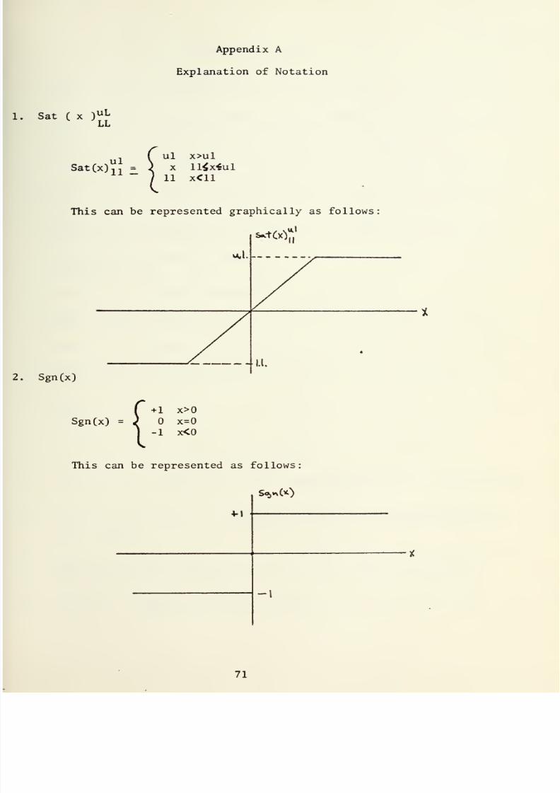
7/25/2019 Analysis and Simulation of a Submarine Steering Control System
http://slidepdf.com/reader/full/analysis-and-simulation-of-a-submarine-steering-control-system 145/162
Appendix
A
Explanation
of
Notation
Sat
(
x
)
uL
LL
Sat(x)
n
ul
x>ul
X
ll$x«ul
11 X<11
This can
be
represented
graphically
as
follows
s*t(xY
Sgn(x)
Sgn(x)
=
+
1 x>0
x=0
-1
x<0
This
can
be
represented
as
follows:
S**00
4-1

7/25/2019 Analysis and Simulation of a Submarine Steering Control System
http://slidepdf.com/reader/full/analysis-and-simulation-of-a-submarine-steering-control-system 146/162

7/25/2019 Analysis and Simulation of a Submarine Steering Control System
http://slidepdf.com/reader/full/analysis-and-simulation-of-a-submarine-steering-control-system 147/162
LIST OF REFERENCES
1.
Morse,
Allen
C.
,
Electrohydraulic
Servomechanisms
,
p.
64,
McGraw-Hill,
1963.
2.
Morse,
Allen
C,
Electrohydraulic Servomechanisms
,
p.
63,
McGraw-Hill,
1963.
3.
Merritt,
H.E.,
Hydraulic
Control Systems
,
p.
215,
Wiley,
1967.
4. Johnson,
G.
,
NAVSHIPRANDCEN,
Code
2762.3,
Personal
Communication.
5.
Morse,
Allen
C.
,
Electrohydraulic Servomechanisms
,
p.
142,
McGraw-Hill,
1963.
6. Kendall,
W.T., Code
260.41,
Mare
Island Naval Ship Yard, Vallejo,
Ca.
94592,
Personal
Communication.
7.
Johnson, Guy,
Unclassified
letter
to
R.H.
Nunn
describing the
simulation,
20
December 1971.
8.
Johnson,
Guy,
Telephone
Communication,
February
1972.
9.
Smith,
Leeland, Code
260.4,
Mare Island
Naval
Ship Yard, Vallejo, Ca.
94952,
Personal Communication.
10.
Keller,
G.R.,
Hydraulic System Analysis
,
pp.
139-142, Industrial,
1969.
11. Kendall, W.T., Code
260.41,
Mare Island Naval
Ship
Yard, Vallejo, Ca.
94592,
Personal Communication.
12.
Chase,
Leonard, Code
260.41,
Mare
Island Naval
Ship
Yard, Vallejo, Ca.
94592.
13.
Merritt, H.E.,
Hydraulic Control
Systems
,
p.
34,
Wiley,
1967.
14. Merritt,
H.E., Hydraulic Control Systems
,
p.
42, 43,
Wiley, 1967.
15. Laughaar ,
H.L.
,
Steady
Flow in the
Transition
Length of a
Straight
Tube
,
Journal of Applied Mechanics,
June
1942,
A55-A58.
16. Krieth,
F., Eisenstadt, R.
,
Pressure Drop and
Flow
Characteristics of
Short
Capillary
Tubes
at
Low~Reynolds
Numbers
,
ASME
Transactions,
July
1957
1070-1078.
17.
Shapiro,
H. , Siegel, and Kline,
J.,
Friction Factor
in the
Laminar
Entry
Region
of
a
Smooth
Tube
,
Proc.
2nd U.S. Natl.
Congress
of
Applied
Mechanics,
June
1954
733-741.
18.
Streeter, V., Handbook
of
Fluid Dynamics
,
1st
Ed.,
pp
13-35,
13-36,
McGraw-Hill,
1961.

7/25/2019 Analysis and Simulation of a Submarine Steering Control System
http://slidepdf.com/reader/full/analysis-and-simulation-of-a-submarine-steering-control-system 148/162

7/25/2019 Analysis and Simulation of a Submarine Steering Control System
http://slidepdf.com/reader/full/analysis-and-simulation-of-a-submarine-steering-control-system 149/162
Theodorson,
T.
,
General
Theory
of
Aerodynamic Instability and
the
Mechanism
of Flutter
,
NACA
Technical
Report No.
496,
1949.
Hughes,
W. , Brighton, J.,
Shaum's
Outline
of
Theory
and
Problems
of
Fluid
Dynamics
,
p.
85.
Okada
,
S
.
,
Investigation
of
the
Effect
of the
Angular Velocity
of
Steering
Upon the
Performance
of_
Rudders
,
Technical
Research
Laboratory,
HITACHI
Shipbuilding and
Engineering
Company,
Ltd.,
1958.
Kennard,
E.,
Leibowitz,
R.
,
Theory
of
Forces
and Moments
on
Rudders
as
Affected
by
Ship
Turning,
Steady
Change
of
Rudder
Angle,
and
Propel
lor
Race
,
NSRDC Acoustics
and Vibrations Laboratory
Technical
Note
AVL-238-940,
pp.
47-71,
January 1969.
Kennard, E.,
Leibowitz, R., Theory of Forces
and
Moments
on Rudders
as
Affected
by Ship Turning,
Steady
Change
of
Rudder
Angle, and
Propellor
Race
,
NSRDC Acoustics
and
Vibrations Laboratory Technical
Note
AVL-238-940,
p.
47,
January
1969.

7/25/2019 Analysis and Simulation of a Submarine Steering Control System
http://slidepdf.com/reader/full/analysis-and-simulation-of-a-submarine-steering-control-system 150/162

7/25/2019 Analysis and Simulation of a Submarine Steering Control System
http://slidepdf.com/reader/full/analysis-and-simulation-of-a-submarine-steering-control-system 151/162
INITIAL
DISTRIBUTION
LIST
No.
Copies
1.
Defense
Documentation
Center
2
Cameron
Station
Alexandria,
Virginia
22314
2.
Library,
Code 0212
2
Naval
Postgraduate
School
Monterey,
California 93940
3.
Professor R.H. Nunn, Code
59
Nn 2
Department
of
Mechanical Engineering
Naval
Postgraduate School
Monterey,
California
93940
4.
Ensign Ernest E. Wessman 2
4901
South
4135 West
Kearns, Utah
84118

7/25/2019 Analysis and Simulation of a Submarine Steering Control System
http://slidepdf.com/reader/full/analysis-and-simulation-of-a-submarine-steering-control-system 152/162

7/25/2019 Analysis and Simulation of a Submarine Steering Control System
http://slidepdf.com/reader/full/analysis-and-simulation-of-a-submarine-steering-control-system 153/162
Security
Classification
DOCUMENT
CONTROL
DATA
-R&D
[Security
classification
of
title,
body
of
abstract and
indexing
annotation
must
be entered when
the overall
report
Is
classified)
IGIN
A Tl NG
ACTIVITY
(Corporate
author)
Postgraduate
School
California 93940
21.
REPORT
SECURITY
CLASSIFICATION
Unclassified
26.
GROUP
TITLE
and Simulation
of
a
Submarine
Steering
Control
System
NOTES
(Type
of
report
and,
in c
I
us /
ve
dates)
Thesis;
June 1972
(First name,
middle
initial,
last name)
Everett
Wessman
T
D A
TE
1972
la. TOTAL NO.
OF
PAGES
76
7b.
NO.
OF
REFS
23
OR
GRANT
NO.
NO.
9a. ORIGINATOR'S
REPORT
NUMBERtS)
96. OTHER REPORT
n
o
(
si
(Any
other
numbers
that
may
ba am
signed
this
report)
STATEMENT
Distribution
limited
to
u.
S. Government
Agencies
only;
information,
8 August
1972.
Other
requests
for
this
document
be
referred
to
Naval
Postgraduate
School,
Monterey,
California,
93940,
Code
023
NOTES
12-
SPONSORING MILITARY
ACTIVITY
Naval Postgraduate
School
Monterey,
California 93940
T
An
existing
computer simulation
of
a
hydraulic
submarine steering control system
analyzed
to
determine the
source
of
its
unrealistic
behavior,
which
included
mathematical
equations
and
numerical
parameters,
duplicating
the
simulation
another
computer, and
investigating
the
validity of the assumptions made
in
its
Rudder
turning
rate
and load
pressure drop
oscillations which
were
to be
unrealistic
were caused by
the
neglect of
significant
rudder
moments
to
the
control
surface turning
rate.
Knowledge
of
actual
system
performance
found
to
be
incomplete
and
further
research
was
suggested.
Potentially
benefi-
modifications
in the
servovalve
and
actuator simulators
were identified.
work
in
the
field
of unsteady
rudder behavior
was
suggested in
order
to
simulator
and
actual system
designs.
i
nov
as
I
*T
/ O
101
-807-681
1
(PAGE
1
75
Security
Classification
A-31408

7/25/2019 Analysis and Simulation of a Submarine Steering Control System
http://slidepdf.com/reader/full/analysis-and-simulation-of-a-submarine-steering-control-system 154/162
7/25/2019 Analysis and Simulation of a Submarine Steering Control System
http://slidepdf.com/reader/full/analysis-and-simulation-of-a-submarine-steering-control-system 155/162
Classification
KEY
WO
ROS
1473
<
BACK
>
1
ROLE
W
T
76
Security
Classification
A-3M09

7/25/2019 Analysis and Simulation of a Submarine Steering Control System
http://slidepdf.com/reader/full/analysis-and-simulation-of-a-submarine-steering-control-system 156/162

7/25/2019 Analysis and Simulation of a Submarine Steering Control System
http://slidepdf.com/reader/full/analysis-and-simulation-of-a-submarine-steering-control-system 157/162

7/25/2019 Analysis and Simulation of a Submarine Steering Control System
http://slidepdf.com/reader/full/analysis-and-simulation-of-a-submarine-steering-control-system 158/162

7/25/2019 Analysis and Simulation of a Submarine Steering Control System
http://slidepdf.com/reader/full/analysis-and-simulation-of-a-submarine-steering-control-system 159/162

7/25/2019 Analysis and Simulation of a Submarine Steering Control System
http://slidepdf.com/reader/full/analysis-and-simulation-of-a-submarine-steering-control-system 160/162

7/25/2019 Analysis and Simulation of a Submarine Steering Control System
http://slidepdf.com/reader/full/analysis-and-simulation-of-a-submarine-steering-control-system 161/162
6
JUL8»
S1
17U8
134783
Thesis
W4764
Wessman
r
-
t
c.l
Analysis
and simula-
tion of
a
submarine
steering
control
sys-
6
J
u
item. S117U8
Thesi
s
W4764
c.l
134789
Wessman
Analysis and simula-
tion
of
a
submarine
steering
control
sys-
tem.

7/25/2019 Analysis and Simulation of a Submarine Steering Control System
http://slidepdf.com/reader/full/analysis-and-simulation-of-a-submarine-steering-control-system 162/162
thesW4764
A
™'.
VS
'
S
and
simulation
of
a
submarine
:
3
2768
001
95006
6
DUDLEY
KNOX
LIBRARY