ALPHA C-25 BATTERY CHARGER - Lamar Tech · ALPHA C-25 BATTERY CHARGER OPERATING MANUAL Lamar...
24
ALPHA C-25 BATTERY CHARGER OPERATING MANUAL Lamar Technologies LLC 14900 40th Ave NE, Marysville WA, 98271 360-651-8869 www.lamartech.com/powerproducts Power Products by Lamar Technologies
Transcript of ALPHA C-25 BATTERY CHARGER - Lamar Tech · ALPHA C-25 BATTERY CHARGER OPERATING MANUAL Lamar...
ALPHA C-25 BATTERY CHARGER
OPERATING MANUAL Lamar Technologies LLC
14900 40th Ave NE, Marysville WA, 98271360-651-8869 www.lamartech.com/powerproducts
Power Productsby
Lamar Technologies

TABLE OF CONTENTS
1. SYSTEM OVERVIEW ................................................... 3
1.1 SYSTEM OVERVIEW ............................................................ 31.2 DISPLAYS AND CONTROLS ................................................ 3
2. INSTALLATION ............................................................ 6
2.1 LINE VOLTAGE ..................................................................... 62.2 TERMINALS ........................................................................... 62.3 SPACE REQUIREMENTS ..................................................... 6
3. OPERATING GUIDE .................................................... 7
3.1 CHARGE CHARACTERISTICS ............................................. 73.2 CHARGING METHODS ......................................................... 83.3 PREPARATION FOR CHARGING ......................................... 93.4 CHARGE TIME .................................................................... 11
4. CALIBRATION AND MAINTENANCE ....................... 15
4.1 OVERVIEW OF CALIBRATION ........................................... 154.2 VOLTAGE VERIFICATION .................................................. 154.3 CURRENT VERIFICATION .................................................. 154.4 SHUNT VERIFICATION ....................................................... 164.5 OPERATING RANGES ........................................................ 164.6 MAINTENANCE ................................................................... 17
5. TROUBLESHOOTING ............................................... 18
6. SPECIFICATIONS ...................................................... 19
APPENDIX A - BATTERY OVERVIEW .............................. 20
CLASSES OF BATTERIES ........................................................... 20SECONDARY BATTERIES ........................................................... 20LEAD-ACID BATTERIES, VENTED OR VRLA .............................. 20NICKEL-CADMIUM BATTERIES .................................................. 21DEFINITIONS ................................................................................ 21
WARRANTY ....................................................................... 22
REPORT AND CERTIFICATION OF CALIBRATION……..23

1. SYSTEM OVERVIEW
ALPHA C-25 Manual V2.1.doc Page 3
1. SYSTEM OVERVIEW
1.1 SYSTEM OVERVIEW The Alpha C-25 Charger is a self-contained unit for charging of rechargeable batteries. It has been designed to charge one or two batteries of the same voltage rating simultaneously, to a combined maximum of 25 amperes. At 40 lbs. and 15 by 5 ¾ inches (381 by 146mm) the C-25 takes minimal space and can easily be moved to add flexibility to the work environment. The charger height and depth are the same as the Power Products’ discharge tester, Beta D-50, with the same general appearance. Therefore, two adjacent units comprise a charger/discharger, which can service from one to three batteries simultaneously, lead-acid or nickel cadmium.
The Alpha C-25 allows charging at both constant potential and constant current to give flexibility in selection of charge method. The C-25 charger has an adjustable charge current from 0 to 25 amperes in the CP (Constant Potential) mode. End of voltage settings should be 14.3 for 12 Volt and 28.5 for 24 Volt batteries. Panel trimpots allow user voltage changes if required. In CC (Constant Current) mode, there is no voltage adjustment. Maximum voltage is approximately 37 volts. Two digital panel meters allow viewing of charge current and voltage. They can be switched to allow viewing of either of the two batteries being charged. A digital electronic timer displays elapsed time and can be set to a fixed duration charge period.
The flexibility of settings of the Alpha C-25 makes it usable for a wide variety of batteries and voltages. The unit efficiently charges Lead Acid batteries of 12 or 24 volts, as well as Nickel Cadmium batteries of a single cell to 24 volts.
1.2 DISPLAYS AND CONTROLS The Alpha C-25 has been designed to have very simple and easy to understand controls and displays (see figure 1-1 and 1-2).
There is a trimpot for the 12 Volt, and a trimpot for the 24 Volt constant potential setting on the front panel for adjustment of the end of charge voltage.

1. SYSTEM OVERVIEW
ALPHA C-25 Manual V2.1.doc Page 4
Figure 1–1. Front view of Alpha C-25
DIGITAL CHARGE TIMER Displays elapsed charge time. Can be set to fixed duration charge times
DIGITAL VOLTMETER Displays battery voltage during charge
CHARGE MODE SELECT KNOB Selects constant current or constant potential mode for 12 or 24 volt batteries
DIGITAL AMMETER Displays charge current
INSTRUCTION PANEL
AMPERE ADJUST KNOB Sets current charge
ON/OFF LAMPS Illuminate to indicate if unit is charging (on) or not (off)
BATTERY VIEW SWITCH Switches between displaying current and voltage for battery one or battery two
AC ON/OFF SWITCH Turns unit on or off
DC LINE FUSE Fuse protecting DC line
START BUTTON Pressed to start charge
DC LINE CONNECTORS Connects for DC cable leading to battery
VOLTAGE ADJUST Trims output voltage

1. SYSTEM OVERVIEW
ALPHA C-25 Manual V2.1.doc Page 5
Figure 1–2. Rear view of Alpha C-25
AC LINE FUSE
AC VOLTAGE SELECT SWITCH Selects mains input voltage (120 or 230 volts)
COOLING FANS
AC MAINS CABLE

2. INSTALLATION
ALPHA C-25 Manual V2.1.doc Page 6
2. INSTALLATION
2.1 LINE VOLTAGE The Alpha C-25 can operate on either 120 or 230 Volts AC. The desired line voltage can be selected on the rear of the unit.
CAUTION: Ensure that the unit is set for the appropriate line voltage before operation.
A. On the back of the unit locate the AC voltage select switch.
B. Set switch for appropriately marked AC voltage (120 or 230 volts).
C. For 230 VAC operation, the 120 VAC plug must be replaced with one for 230 VAC in required configuration.
NOTE: If the plug has to be changed make sure to connect the green AC line wire to ground.
Connect the unit to a wall outlet with a 15-20 ampere capacity. Sharing of the line with other equipment may result in erratic operation if other equipment draws high pulse or surge currents.
NOTE: The Alpha C-25 will maintain its operational integrity with line fluctuation less than ± 5%.
2.2 TERMINALS The Alpha C-25 is supplied with two DC cables. One cable has an aircraft battery quick-disconnect connector and one has ring terminals. If the quick-disconnect connector is removed, the ring terminals can be used to connect to a post terminal battery, or be fitted to a different quick-disconnect connector.
WARNING: Correct polarity must be observed.
2.3 SPACE REQUIREMENTS The Alpha C-25 system occupies 15" x 5 ¾" (381 mm x 146 mm) of tabletop space. Place the unit on a sturdy workbench in a well-ventilated battery servicing area with the battery adjacent to it.
2. INSTALLATION
ALPHA C-25 Manual V2.1.doc Page 7
The rear of the unit has air flow for cooling. Allow at least 6" (150 mm) of separation from the wall and adjacent equipment in order to maintain proper air flow.
NOTE: In non air-conditioned rooms it is recommended that circulating or extracting fans be used to aid in the removal of heated air.
NOTE: Operation in dusty or otherwise dirty air environments will severely reduce the cooling capacity of the fans and can lead to premature failure.
3. OPERATING GUIDE
This section gives an overview of how to charge a battery using the Alpha C-25. Always refer to the battery manufacturers’ maintenance manual for their recommended charging methods and settings.
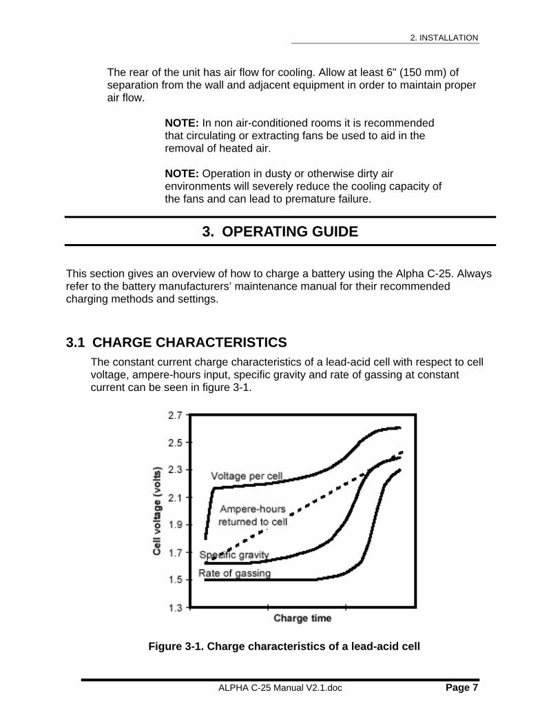
3.1 CHARGE CHARACTERISTICS The constant current charge characteristics of a lead-acid cell with respect to cell voltage, ampere-hours input, specific gravity and rate of gassing at constant current can be seen in figure 3-1.
Figure 3-1. Charge characteristics of a lead-acid cell

3. OPERATING GUIDE
ALPHA C-25 Manual V2.1.doc Page 8
As shown by the curve in figure 3-1 the cell voltage of a discharged battery rises rapidly when the battery is first placed on charge. The extent of the initial rise depends on the charging rate. As the charge continues, the voltage rises at a slower rate and eventually levels off when a full state-of-charge is reached. It can be seen that the specific gravity reading lags behind the rate of ampere-hour return during most of the charging cycle. Consequently, the specific gravity is not indicative of the available ampere-hour capacity until the cell approaches a full-charge state. When a battery reaches a full state-of-charge the voltage of the battery will stabilize and remain constant or decrease (in constant current mode). The charging should discontinue at this stage. A minimum of 103% of previous discharge should be placed in the battery.
In general a vented battery may be charged at any rate that will not produce excessive gassing or electrolyte temperatures above 113°F (45°C). VRLA batteries should never be charged in a constant-current mode with a current greater than C1/10 (C1 equals the rated capacity of the battery). During constant current charging at a rate in excess of C1/10, oxygen is produced at an excessive rate. The resulting increasing pressure will cause the cell to vent. Venting of gasses results in a depletion of electrolyte. As the electrolyte cannot be replaced in a sealed battery, the cell will dry out resulting in a decrease in capacity and eventually battery failure. Therefore constant-potential charging is the recommended charge method for valve regulated lead acid batteries
3.2 CHARGING METHODS There are two main methods of charging a battery: 1) Constant current (CC)2) Constant potential (CP)
In what follows both methods will be described in some detail.
3.2.1 CONSTANT-CURRENT CHARGE METHOD In this method the current remains at a preset level while the voltage can reach a high level, e.g. 34-37 volts.
An advantage of the constant-current charge method is that the ampere-hour input into the battery can be determined precisely by multiplying the charging current with the charge time in hours. However, it is necessary to ensure that the battery is not charged at a high rate for an excessive period of time. Such overcharging can result in overheating, excessive gassing, and possible damage to the battery.

3. OPERATING GUIDE
ALPHA C-25 Manual V2.1.doc Page 9
3.2.2 CONSTANT-POTENTIAL CHARGE METHOD A charge source applies a fixed (constant) voltage (potential) to the battery. The current supplied by the charge source fluctuates (rises and falls) with the battery voltage.
There are several advantages of the constant-potential charge method. First, there is less danger of gassing at an excessive rate. Secondly, batteries of the same nominal voltage but with different capacities can be connected in parallel directly to the charging source. Thirdly, batteries are charged more rapidly and with less attention.
3.2.3 LEAD-ACID BATTERIES With the constant-current charge method the voltage can climb to 34-37 volts. Therefore, this method should normally not be used to charge lead-acid batteries, especially not the sealed type VRLA (valve regulated lead acid). A preferred way is to have the VRLA batteries constant-potential charged on automatic equipment at a voltage of 28.5 +/ – 0.25 volts until the charge current stabilizes for 3 consecutive hourly readings.
The constant-current charge method can however be used for reconditioning VRLA’s. For conditioning VRLA batteries, first discharge 12 volt batteries to 9 volts or 24 volt batteries to 18 volts, then recharge with CC (constant current) at the C1/10 rate (one tenth of the C1 rate or one hour capacity) for 16 hours. The battery should be periodically monitored for overheating during reconditioning.
3.2.4 NICKEL-CADMIUM BATTERIES Nickel-cadmium batteries may be initially charged with constant potential set to 14.5 (12 volt battery) or 28.6 (24 volt battery). After the initial charge the batteries may be topped with a low constant-current (usually C1/10) charge.
The nickel-cadmium can also be completely charged in the constant-current mode. Adjust the current to a lower rate for topping. A low constant current applied during a long time can also be used to eliminate fading, previously called the “memory effect”, from nickel-cadmium batteries.
3.3 PREPARATION FOR CHARGING Before starting charging the battery, read the component maintenance manual (CMM) or the Instructions for Continued Airworthiness (ICA) for the specific battery. Ensure that the charge time and current or voltages from the battery manufacturer are followed.

3. OPERATING GUIDE
ALPHA C-25 Manual V2.1.doc Page 10
It is recommended that a visual inspection of the battery is carried out in conjunction with testing and charging batteries. The charging, unless otherwise specified in the manufacturer's CMM/ ICA, shall be conducted at room ambient temperature of 70°F to 85°F (21°C to 29°C).
3.3.1 VERIFY THE CP VOLTAGE The CP voltage (in all modes) can be verified by the following steps: 1) turn unit power off; 2) disconnect all batteries; 3) turn charge current to max; 4) turn unit power on; and 5) verify the CP voltage on the Alpha C-25 digital voltmeter (see also section 4.5 on modifying the operating range).
WARNING: Always turn the AC power switch off before connecting or disconnecting a battery
NOTE: Once set, all settings are maintained and need not be reset for duplicate charging
A. SWITCH OFF MAINS POWER Turn off the AC on-off/reset power switch.
B. TURN DOWN CHARGE CURRENTRepeatedly turn the Ampere Adjust knob fully counter-clockwise to set charge current to zero.

3. OPERATING GUIDE
ALPHA C-25 Manual V2.1.doc Page 11
3.4 CHARGE TIME
3.4.1 TIMER UNIT SETTING The Alpha C-25 has a built in timer, allowing charge time settings from 0.1 to 999.9 minutes.
3.4.2 CHARGE TIME SETTING The charge time will be set based on the state of charge of the battery and at which rate the battery is being charged.
Refer to your battery manufacturer's CMM (Component Maintenance Manual) or ICA (Instructions for Continued Airworthiness) for the most accurate information.
C. SET TIMER Set the timer by pushing buttons up or down to the required charge time.
D. SELECT CHARGE MODE Turn the Charge Mode Select knob to the desired mode: 1) Constant potential 14.3 volts (lead acid); 2) Constant current; or 3) Constant potential 28.5 volts. If two batteries are to be charged simultaneously, they will both be charged using the selected charge mode.

3. OPERATING GUIDE
ALPHA C-25 Manual V2.1.doc Page 12
E. CONNECT ONE OR TWO BATTERIES Connect the battery DC cable(s) to the Alpha C25 DC Line Connectors on the front of the unit. For single battery always use “BATTERY 1” output. Connect the other end of the cable(s) to the battery (or batteries). Ensure the connectors are plugged in completely.
F. SET BATTERY VIEW Set the battery view switch to “VIEW BATT. 1”
G. SWITCH ON MAINS POWER Turn on the AC on/off power switch. The voltmeter reads the battery terminal voltage, the ammeter reads zero, the Off lamp illuminates and the red LED on the timer is off.

3. OPERATING GUIDE
ALPHA C-25 Manual V2.1.doc Page 13
H. PUSH START BUTTON The timer starts. The On lamp and the red LED on the timer illuminate. The voltmeter displays the battery terminal voltage and the ammeter reads zero.
I. SET CHARGE CURRENT
1. FOR CONSTANT-CURRENTCHARGING Turn the Ampere Adjust knob until the desired charge current has been reached. The charge current is displayed on the ammeter as the current is being adjusted.
2. FOR CONSTANT-POTENTIALCHARGING Turn the Ampere Adjust knob to max (fully clockwise) or to the desired current limit. The charge current is displayed on the ammeter as the current is being adjusted.
3. OPERATING GUIDE
ALPHA C-25 Manual V2.1.doc Page 14
J. WAIT FOR THE CHARGE TO AUTOMATICALLY COMPLETE During the charging of the battery the battery voltage, charge current, and elapsed charge time are displayed.
For the constant-current method the current remains constant whilethe voltage increases during the time of charging.
For the constant-potential method the charger’s end voltage remainsconstant while the current starts at a high value and graduallyapproaches zero as the battery approaches a full charge.
The actual charge current is determined by the battery, until the constant voltage is reached (14.3 volts for 12 volt lead-acid batteries and 28.5 volts for 24 volt batteries).
The charging time ends when the current remains constant (within 10%) for 3 consecutive hourly readings or the set charge time has been reached. The Off lamp illuminates.
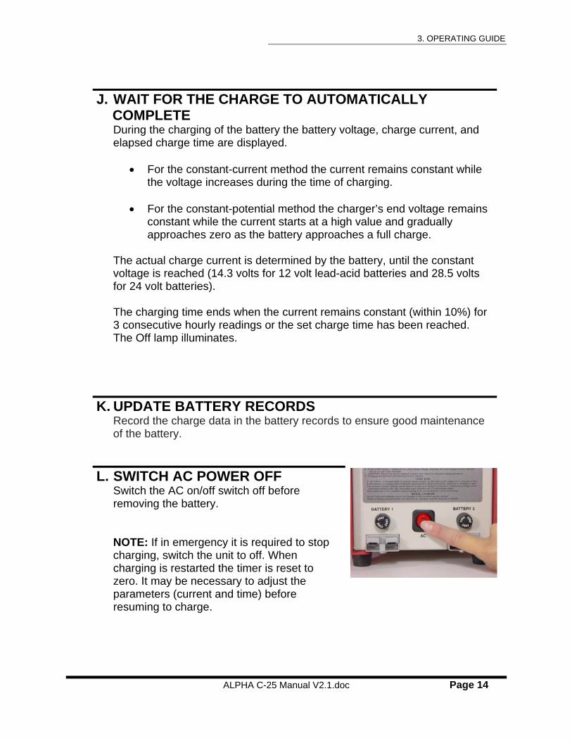
K. UPDATE BATTERY RECORDS Record the charge data in the battery records to ensure good maintenance of the battery.
L. SWITCH AC POWER OFF Switch the AC on/off switch off before removing the battery.
NOTE: If in emergency it is required to stop charging, switch the unit to off. When charging is restarted the timer is reset to zero. It may be necessary to adjust the parameters (current and time) before resuming to charge.

4. CALIBRATION AND MAINTENANCE
ALPHA C-25 Manual V2.1.doc Page 15
4. CALIBRATION AND MAINTENANCE
4.1 OVERVIEW OF CALIBRATION The Alpha C-25 has been calibrated before shipment from the manufacturer. A certificate of calibration with test instruments traceable to the National Institute of Standards and Testing has been issued and is enclosed in the back of this manual. To ensure error-free operation over time, calibration should be verified every 12 months depending on usage and changes in surrounding environment.
4.1.1 DIGITAL PANEL METERS There are two main indicators that can be periodically verified: 1) the voltmeter; and 2) the ammeter (see figure 1-1 in section 1). In addition the internal shunt, even though calibrated and certified by the shunt manufacturer, could be verified.
4.1.2 TIMER The timer is a very accurate crystal-controlled device, not prone to error. It cannot be re-calibrated, but unless an extremely accurate time reading is required, an accurate analog or digital stop watch is adequate to validate its accuracy.
4.1.3 OPERATING RANGES The Alpha C-25 gives the capabilities with panel mounted trimpot to modify the charge voltage in constant-potential mode. There is no adjust for voltage limit in constant current.
4.2 VOLTAGE VERIFICATION
The Alpha C-25 Battery Charger now includes external test point jacks for voltage and current verification.
Voltage Verification - Do not connect C-25 to battery. Select 28.5 V setting. Using an external calibrated digital meter (set to DC Volt scale), connect to voltmeter test jacks and verify voltage panel meter is within approximately 0.3 volts.
4.3 CURRENT VERIFICATION
Connect C-25 to a discharged battery and charge at approx. 20 Amps. Using an external calibrated digital meter (set to millivolt scale), connect to ammeter test jacks and verify panel meter is within approx. 0.3 Amps.
4. CALIBRATION AND MAINTENANCE
ALPHA C-25 Manual V2.1.doc Page 16
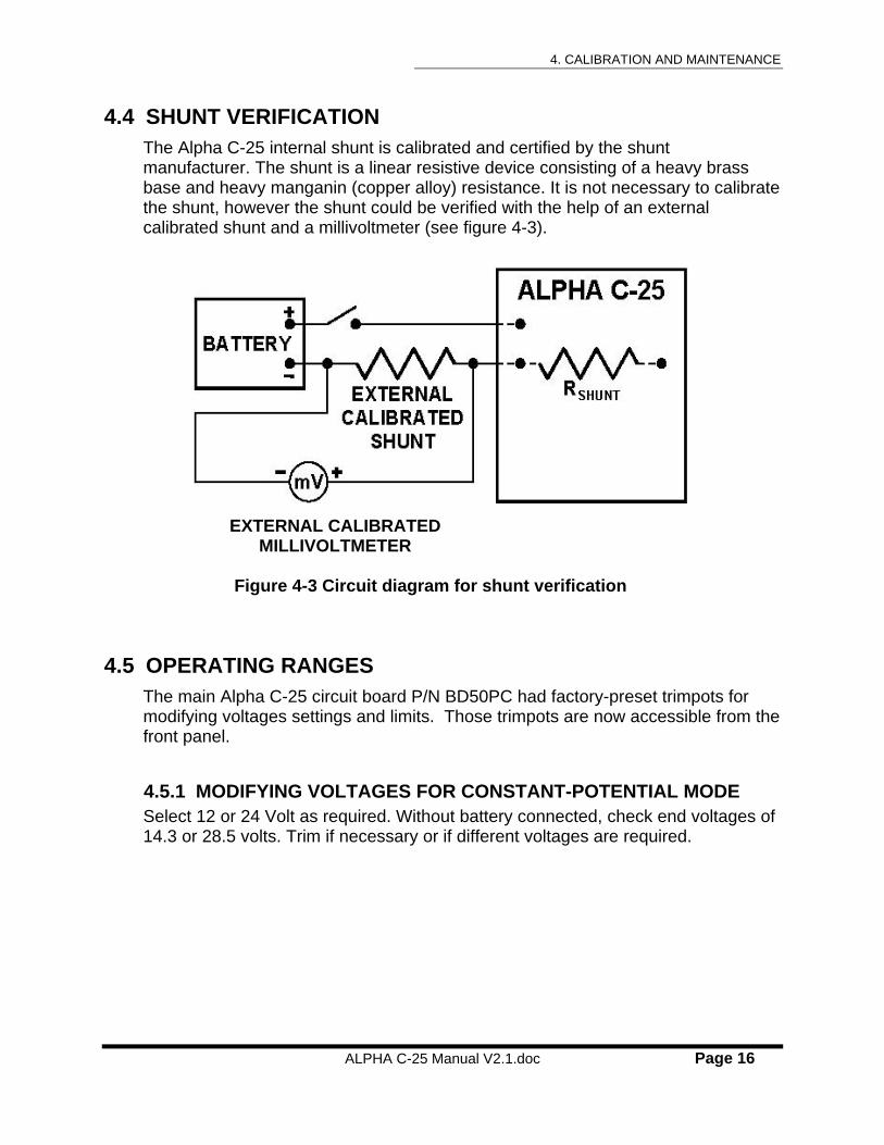
4.4 SHUNT VERIFICATION The Alpha C-25 internal shunt is calibrated and certified by the shunt manufacturer. The shunt is a linear resistive device consisting of a heavy brass base and heavy manganin (copper alloy) resistance. It is not necessary to calibrate the shunt, however the shunt could be verified with the help of an external calibrated shunt and a millivoltmeter (see figure 4-3).
EXTERNAL CALIBRATED MILLIVOLTMETER
Figure 4-3 Circuit diagram for shunt verification
4.5 OPERATING RANGES The main Alpha C-25 circuit board P/N BD50PC had factory-preset trimpots for modifying voltages settings and limits. Those trimpots are now accessible from the front panel.
4.5.1 MODIFYING VOLTAGES FOR CONSTANT-POTENTIAL MODE Select 12 or 24 Volt as required. Without battery connected, check end voltages of 14.3 or 28.5 volts. Trim if necessary or if different voltages are required.

4. CALIBRATION AND MAINTENANCE
ALPHA C-25 Manual V2.1.doc Page 17
4.6 MAINTENANCE Standard electrical equipment maintenance and cleaning procedures should be followed.
4.6.1 VENTS AND FAN Regularly check that the rear fan vents are clean to ensure adequate cooling of the unit. This is especially important when the unit is placed in a dusty or otherwise dirty air environment.
4.6.2 DC BATTERY CABLES Inspect DC battery cables and connectors periodically. Replace damaged or worn cable.
4.6.3 REPLACEMENT OF FUSES The Alpha C-25 is equipped with three fuses: one 20 ampere AC line fuse and two 35 ampere DC line fuses. See specification in section 6 for the specific types of fuses required.
WARNING: Disconnect AC voltage and battery before attempting to replace any fuses.
To replace the AC line fuse unscrew the fuse cover on the rear of the unit and exchange the old fuse (see picture 1-2 in section 1).
To replace the DC line fuses unscrew the fuse cover just above the DC Line Connector and exchange the old fuse (see picture 1-1 in section 1).
4.6.4 CLEANING AGENTS Do not use acetone and other similar cleaning agents on the meters, timer or any plastic part.

6. SPECIFICATIONS
ALPHA C-25 Manual V2.1.doc Page 18
5. TROUBLESHOOTING
Problem Possible Cause Corrective Action
A. Unit will not turn on
The AC power is not connected to unit
Check AC line with voltmeter
AC line fuse is blown. May be due to incorrect AC line voltage setting.
Ensure correct AC line voltage setting on back of unit. (see section 2.1)
Replace AC line fuse located on the lower right hand side on the rear of the unit (see section 4.6)
B. Unit turns on but will not start (timing)
Timer is set to zero time, Increase the timer setting (see section 3.4)
C. No or very low charge current
The lead-acid battery is sulfated and will not support a load
Recondition or discard the battery
High resistance or open circuit in DC cable at quick disconnect, in the cable itself
Inspect and measure resistance in DC cable and connector. If high or intermittent high resistance, the cable needs to be replaced
The lead-acid battery is sulfated.
Recondition the battery.
The nickel-cadmium battery inter-cell connectors are loose or contaminated causing high resistance
Check all terminals and inter-cell connectors. Set a low discharge current and look for arcing or heat generation.
D. Timer setting cannot be changed
Timer setting is locked. Push timer’s “Lock” button.

6. SPECIFICATIONS
ALPHA C-25 Manual V2.1.doc Page 19
6. SPECIFICATIONS
AC Line Input: 120 volts ± 5%, 50/60Hz, 13 amperes or
230 volts ± 5%, 50/60Hz, 6 amperes (selectable on rear of unit) NOTE: Unit will operate ± 10% but with lower max amp ratings at -10%.
Constant Current Mode:
Capacity
Accuracy
Approx. 37 volt limit non-adjustable. 0-7 to 8 amps at 37 volts. < ± 3% from charge initiation to completion
Constant Potential Mode
Setting Selectable 14.3/28.5 volts; 25 ampere limit. Adjustable.
Accuracy < ± 0.2 volts
Timer Setting Adjustable from 0 to 999.9 minutes
Units Selectable on front of timer from 0.1 to 999.9 minutes
Accuracy < ± 0.1%
Digital Meter Accuracy:
Voltmeter < ± 0.3 volts
Ammeter < ± 0.3 amperes
Cooling: Fan cooled
Housing: Aluminum chassis
Outer Dimensions: Height 14 in. (356 mm)
Depth 15 in. (381 mm)
Width 5 3/4 in. (146 mm)
AC Line Cord: AWG 14 3 wire grounded 6 ft long with 120 volt 15 ampere plug. User required to change to 230 volt plug if needed.
DC Discharge Cable:
Two 4 ft long, terminated in ring terminals (Aircraft Battery Connector Optional)
Weight: Net weight 45 lbs (20.4 kg).
Fuses: AC line fuse 20A/250V, type MDA 1 1/4 x 1/4
DC line fuses Two 35A/32V, type AGC 1 1/4 x 1/4
Modes: 1) Constant Current mode without voltagelimit 2) Constant Potential mode for 12 volt and24 volt batteries.

APPENDIX A – BATTERY OVERVIEW
ALPHA C-25 Manual V2.1.doc Page 20
APPENDIX
APPENDIX A - BATTERY OVERVIEW
CLASSES OF BATTERIES Batteries can be divided into two major classes: primary and secondary. The primary batteries are not practically reusable once its useful energy has been discharged. The secondary battery is rechargeable. In the following only secondary batteries will be covered.
SECONDARY BATTERIES Secondary batteries differ from primary batteries in that they may be recharged. Some of the materials in the cells of primary batteries are usually consumed in the process of changing chemical energy into electrical energy. In the secondary system, the materials are transferred from one electrode to the other as the cells discharge. The cells are restored to their original state of charge by forcing an electric current through the cells in a direction opposite to that of the discharge. These batteries are used in a multitude of applications ranging from megawatt sizes in submarines to milliwatt sizes in portable radios.
LEAD-ACID BATTERIES, VENTED OR VRLA
The lead-acid battery is a rechargeable system using acid electrolyte (sulfuric acid and water). Lead-acid batteries may be vented or sealed. The advantages of lead-acid batteries are that they have a low initial cost, require low maintenance, and their discard cost is low. The VRLA batteries, on a per-weight basis, provides as much power as a nickel-cadmium battery. Vented Lead-acid batteries shed active material from the positive plate, proportional to the number of charge/discharge cycles. For Vented lead-acid batteries this results in diminishing battery performance with age and loss of active material on the positive plates due to the washing action of the gas bubbles generated during charge. The open circuit voltage of a fully charged cell is about 2.15-2.20 volts. The discharge voltage is about 2.0 volts and varies with temperature, discharge rate, charge state, and age. The VRLA batteries are normally charged in the CP mode.
The lead-acid battery is the most widely used of the secondary battery types. Major applications include automobiles, aircraft, aircraft support equipment, and various industrial applications.

APPENDIX A – BATTERY OVERVIEW
ALPHA C-25 Manual V2.1.doc Page 21
NICKEL-CADMIUM BATTERIES The nickel-cadmium battery is a rechargeable system using alkaline electrolyte (a 31% aqueous solution potassium hydroxide). Nickel-cadmium batteries, which may be vented or sealed, have overcharge capability, high rate charge acceptance and nearly constant discharge voltage. The disadvantages are the high initial and maintenance costs as well as the cost to discard the battery at the end of life. The open circuit voltage of a fully charged cell is about 1.35 volts. The discharge voltage is about 1.2 to 1.1 volts and varies with temperature, discharge rate, charge state, and age.
Nickel-cadmium batteries are used in auxiliary power units, aircraft engine starting, space satellite power, missile electrical systems, and electrical propulsion
DEFINITIONS AMPERE-HOURS. The term "ampere-hours" is a unit of measure that refers to the electrical capacity of a battery. It is the product of the current in amperes multiplied by the period of time in hours during which the current is delivered. For example, a battery that discharges at 5.0 amperes for 4.0 hours has delivered 5.0 x 4.0 or 20 ampere-hours. To convert ampere-minutes to ampere-hours, simply divide by 60. E.g. 10 amperes x 40 minutes = 400/60 ampere-hours = 6.6 ampere-hours.
END POINT VOLTAGE. The End Point Voltage is the end point of the discharge curve, for a specified discharge rate, at which the battery or cell is considered to be discharged for all practical purposes. Lead acid batteries can be permanently damaged if discharged below their END POINT VOLTAGE.
CAPACITY RATE (C1-RATE). The capacity rating of a lead-acid or nickel-cadmium
battery is based on a one hour discharge rate with the battery initially at temperature 77.5°F (25°C) and a cutoff terminal voltage of 20.0 volts for a 24-volt battery or 10.0 volts for a 12-volt battery. For example, a 24-volt battery rated at 30.0 ampere-hours should deliver 30.0 amperes for a minimum of 51 minutes before reaching the 20 volt EPV (end point voltage) . This is a one-hour, C
1-rate discharge.
WARRANTY
ALPHA C-25 Manual V2.1.doc Page 22
WARRANTY
1 YEAR WARRANTY
POWER PRODUCTS warrants its products to be free from defects in workmanship and material for a one year period from the date of shipment to the distributor, original equipment manufacturer (OEM), or original end user. If any product shall prove to be defective during the warranty period, POWER PRODUCTS will repair or replace such part.
There are no warranties which extend beyond the description on the face hereof. This warranty is in lieu of all other warranties, express or implied. POWER PRODUCTS excludes liability for incidental and consequential damages.
An action for breach of this warranty must be commenced within one year after the breach is or should have been discovered.
POWER PRODUCTS specifically disclaims all other representations to the first user/ purchaser, and all other obligations or liabilities. No person is authorized to give any other warranties or to assume any liabilities on POWER PRODUCTS’ behalf.

CERTIFICATION OF CALIBRATION
ALPHA C-25 Manual V2.1.doc Page 23
REPORT AND CERTIFICATION OF CALIBRATION
Lamar Technologies LLC, 14900 40th Ave. NEMarysville, WA 98271 360-651-8869 www.lamartech.com/powerproducts
Date of Test ___________
S/N _____________ Model Alpha C-25_ MFR Date ________
Description:
Military Battery Charging Battery Discharge
Commercial Combination Charger/Discharger
NSN: 6130-01-462-6335 & 6130-21-258-4429
Notes on Calibration:
1. All instruments used for calibration are calibrated to standards traceable toNational Institute of Standards and Technology.
2. Test instruments are calibrated annually by a certified test laboratory incompliance with the Calibration Systems Requirement of ISO/IE17025:2005, ANSI/NCSL Z540-1-1994, and a quality system registered to ISO 9001:2008
Report: Test Instruments Used:
Fluke 8010A Fluke 73
Empro Standard Shunt,0.5% Leader Oscilloscope LS1020
Standard Cell Reference: Other: _____________________ EMF Reading for Multimeter before each test to 1.019V.
Results:
All controls within specification.
All digital/analog displays within calibration specification.
Shipped condition all in tolerance, passed.
Tested by _________ Date _________ Approved By _________ Date _________
Calibration due one year from date of first use: Recommended Required

ALPHA C-25 Manual V2.1.doc Page 24
Designer and manufacturer of aircraft lead-acid and nickel-cadmium battery support equipment since 1980. Headquarters located in Santa Clara, California.
CONTACT INFORMATION:
Lamar Technologies LLC14900 40th Ave NEMarysville, WA 98271360-651-8869 fax 360-651-6677www.lamartech.com
Power ProductsbyLamar Technologies