
Agilent InfinityLab Quick Change Valves G4231A/C … Delivery Checklist Check the content of the...
28
Agilent Technologies Agilent InfinityLab Quick Change Valves G4231A/C and G4232C/D Instructions Quick Change Valves G4231A/C and G4232C/D This technical note describes the installation and application of the Agilent InfinityLab Quick Change 2ps/6pt Valve Heads G4231A/C and 2ps/10pt Valve Heads G4232C/D in a 1260/1290 Infinity II Multicolumn Thermostat (MCT). Contents Typical Applications 2 Dual column selection (2ps/6pt or 2ps/10pt valve heads) 2 Sample enrichment and sample cleanup (2ps/6pt or 2ps/10pt valve heads) 3 Alternating Column Regeneration (2ps/10pt valve heads only) 5 Delivery Checklist 6 Specifications 13 Installation 15 Installation of the Valve Heads 15 Install Heat Exchanger 21 Install the Capillaries 25 Valve Parts 27
Transcript of Agilent InfinityLab Quick Change Valves G4231A/C … Delivery Checklist Check the content of the...
Agilent InfinityLab Quick Change Valves G4231A/C and G4232C/DInstructions
Quick Change Valves G4231A/C and G4232C/D
This technical note describes the installation and application of the Agilent InfinityLab Quick Change 2ps/6pt Valve Heads G4231A/C and 2ps/10pt Valve Heads G4232C/D in a 1260/1290 Infinity II Multicolumn Thermostat (MCT).
Contents
Typical Applications 2Dual column selection (2ps/6pt or 2ps/10pt valve heads) 2Sample enrichment and sample cleanup (2ps/6pt or 2ps/10pt valve heads) 3Alternating Column Regeneration (2ps/10pt valve heads only) 5
Delivery Checklist 6
Specifications 13
Installation 15Installation of the Valve Heads 15Install Heat Exchanger 21Install the Capillaries 25
Valve Parts 27
Agilent Technologies
Typical Applications
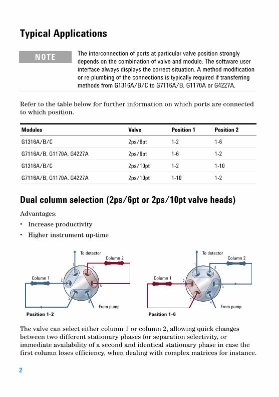
Refer to the table below for further information on which ports are connected to which position.
Dual column selection (2ps/6pt or 2ps/10pt valve heads)Advantages:
• Increase productivity
• Higher instrument up-time
The valve can select either column 1 or column 2, allowing quick changes between two different stationary phases for separation selectivity, or immediate availability of a second and identical stationary phase in case the first column loses efficiency, when dealing with complex matrices for instance.
NOTE The interconnection of ports at particular valve position strongly depends on the combination of valve and module. The software user interface always displays the correct situation. A method modification or re-plumbing of the connections is typically required if transferring methods from G1316A/B/C to G7116A/B, G1170A or G4227A.
Modules Valve Position 1 Position 2
G1316A/B/C 2ps/6pt 1-2 1-6
G7116A/B, G1170A, G4227A 2ps/6pt 1-6 1-2
G1316A/B/C 2ps/10pt 1-2 1-10
G7116A/B, G1170A, G4227A 2ps/10pt 1-10 1-2
2
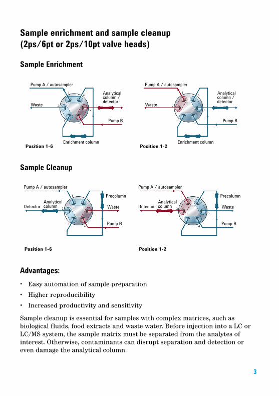
Sample enrichment and sample cleanup (2ps/6pt or 2ps/10pt valve heads)
Sample Enrichment
Sample Cleanup
Advantages:• Easy automation of sample preparation
• Higher reproducibility
• Increased productivity and sensitivity
Sample cleanup is essential for samples with complex matrices, such as biological fluids, food extracts and waste water. Before injection into a LC or LC/MS system, the sample matrix must be separated from the analytes of interest. Otherwise, contaminants can disrupt separation and detection or even damage the analytical column.
3
Enrichment methodsEnrichment methods are the techniques of choice to obtain highest sensitivity and to remove the sample matrix in such applications as proteomics, drug metabolism and environmental trace analysis. The analytes are retained and concentrated onto the pre-column, while the sample matrix is passed to waste. After the valve switch, a second pump backflushes the analytes out of the pre-column onto the separation column. This allows injection of large volumes onto the pre-column, significantly expanding sensitivity in the range of ten to several thousands.
Sample cleanupCleanup methods handle analytes and matrices in the opposite way to enrichment methods. Matrix components are retained on the precolumn while the analytes pass through to the separation column. After the valve switches, an additional pump backflushes the matrix components out of the precolumn to waste, while the analytes are separated on the main column. Backflushing prepares the precolumn for the next injection.
4
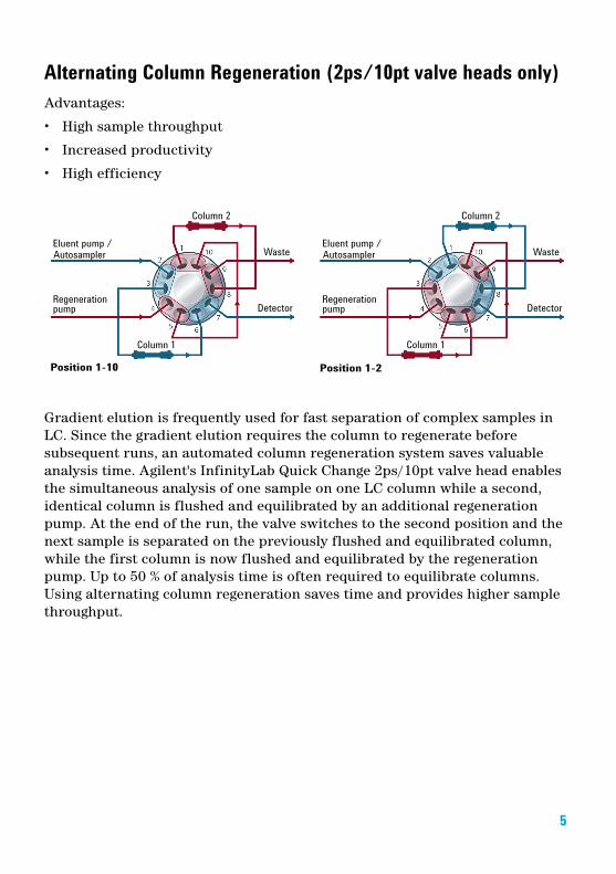
Alternating Column Regeneration (2ps/10pt valve heads only)Advantages:
• High sample throughput
• Increased productivity
• High efficiency
Gradient elution is frequently used for fast separation of complex samples in LC. Since the gradient elution requires the column to regenerate before subsequent runs, an automated column regeneration system saves valuable analysis time. Agilent's InfinityLab Quick Change 2ps/10pt valve head enables the simultaneous analysis of one sample on one LC column while a second, identical column is flushed and equilibrated by an additional regeneration pump. At the end of the run, the valve switches to the second position and the next sample is separated on the previously flushed and equilibrated column, while the first column is now flushed and equilibrated by the regeneration pump. Up to 50 % of analysis time is often required to equilibrate columns. Using alternating column regeneration saves time and provides higher sample throughput.
5
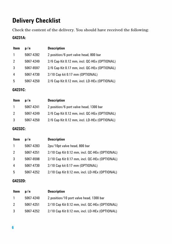
Delivery ChecklistCheck the content of the delivery. You should have received the following:
G4231A:
G4231C:
G4232C:
G4232D:
Item p/n Description
1 5067-4282 2 position/6 port valve head, 800 bar
2 5067-4249 2/6 Cap Kit 0.12 mm, incl. QC-HEx (OPTIONAL)
3 5067-6597 2/6 Cap Kit 0.17 mm, incl. QC-HEx (OPTIONAL)
4 5067-4730 2/10 Cap kit 0.17 mm (OPTIONAL)
5 5067-4250 2/6 Cap Kit 0.12 mm, incl. LD-HEx (OPTIONAL)
Item p/n Description
1 5067-4241 2 position/6 port valve head, 1300 bar
2 5067-4249 2/6 Cap Kit 0.12 mm, incl. QC-HEx (OPTIONAL)
3 5067-4250 2/6 Cap Kit 0.12 mm, incl. LD-HEx (OPTIONAL)
Item p/n Description
1 5067-4283 2ps/10pt valve head, 800 bar
2 5067-4251 2/10 Cap Kit 0.12 mm, incl. QC-HEx (OPTIONAL)
3 5067-6598 2/10 Cap Kit 0.17 mm, incl. QC-HEx (OPTIONAL)
4 5067-4730 2/10 Cap kit 0.17 mm (OPTIONAL)
5 5067-4252 2/10 Cap Kit 0.12 mm, incl. LD-HEx (OPTIONAL)
Item p/n Description
1 5067-4240 2 position/10 port valve head, 1300 bar
2 5067-4251 2/10 Cap Kit 0.12 mm, incl. QC-HEx (OPTIONAL)
3 5067-4252 2/10 Cap Kit 0.12 mm, incl. LD-HEx (OPTIONAL)
6
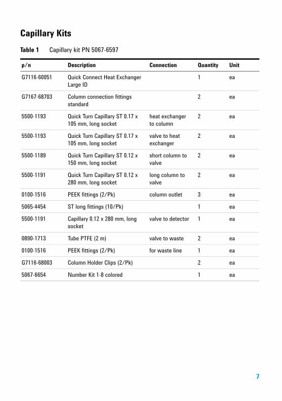
Capillary KitsTable 1 Capillary kit PN 5067-6597
p/n Description Connection Quantity Unit
G7116-60051 Quick Connect Heat Exchanger Large ID
1 ea
G7167-68703 Column connection fittings standard
2 ea
5500-1193 Quick Turn Capillary ST 0.17 x 105 mm, long socket
heat exchanger to column
2 ea
5500-1193 Quick Turn Capillary ST 0.17 x 105 mm, long socket
valve to heat exchanger
2 ea
5500-1189 Quick Turn Capillary ST 0.12 x 150 mm, long socket
short column to valve
2 ea
5500-1191 Quick Turn Capillary ST 0.12 x 280 mm, long socket
long column to valve
2 ea
0100-1516 PEEK fittings (2/Pk) column outlet 3 ea
5065-4454 ST long fittings (10/Pk) 1 ea
5500-1191 Capillary 0.12 x 280 mm, long socket
valve to detector 1 ea
0890-1713 Tube PTFE (2 m) valve to waste 2 ea
0100-1516 PEEK fittings (2/Pk) for waste line 1 ea
G7116-68003 Column Holder Clips (2/Pk) 2 ea
5067-6654 Number Kit 1-8 colored 1 ea
7
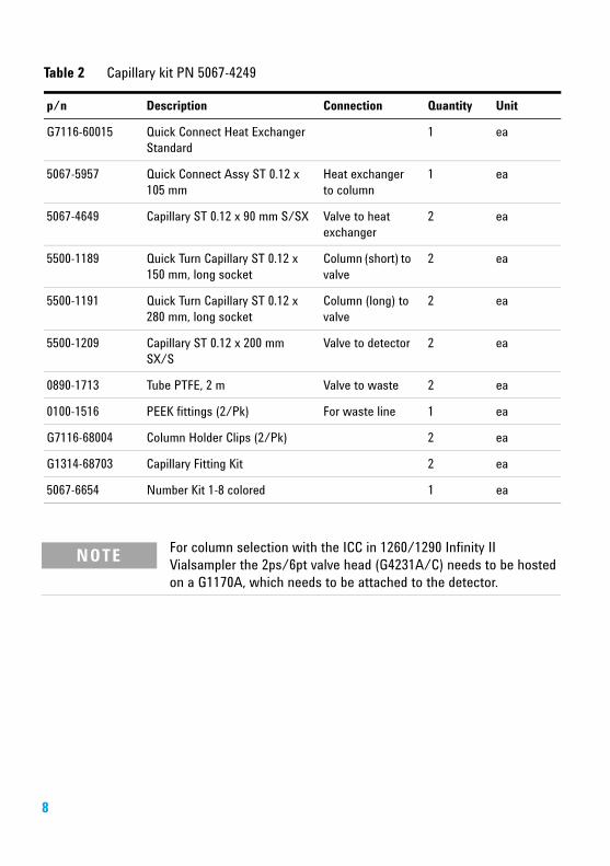
Table 2 Capillary kit PN 5067-4249
p/n Description Connection Quantity Unit
G7116-60015 Quick Connect Heat Exchanger Standard
1 ea
5067-5957 Quick Connect Assy ST 0.12 x 105 mm
Heat exchanger to column
1 ea
5067-4649 Capillary ST 0.12 x 90 mm S/SX Valve to heat exchanger
2 ea
5500-1189 Quick Turn Capillary ST 0.12 x 150 mm, long socket
Column (short) to valve
2 ea
5500-1191 Quick Turn Capillary ST 0.12 x 280 mm, long socket
Column (long) to valve
2 ea
5500-1209 Capillary ST 0.12 x 200 mm SX/S
Valve to detector 2 ea
0890-1713 Tube PTFE, 2 m Valve to waste 2 ea
0100-1516 PEEK fittings (2/Pk) For waste line 1 ea
G7116-68004 Column Holder Clips (2/Pk) 2 ea
G1314-68703 Capillary Fitting Kit 2 ea
5067-6654 Number Kit 1-8 colored 1 ea
NOTE For column selection with the ICC in 1260/1290 Infinity II Vialsampler the 2ps/6pt valve head (G4231A/C) needs to be hosted on a G1170A, which needs to be attached to the detector.
8
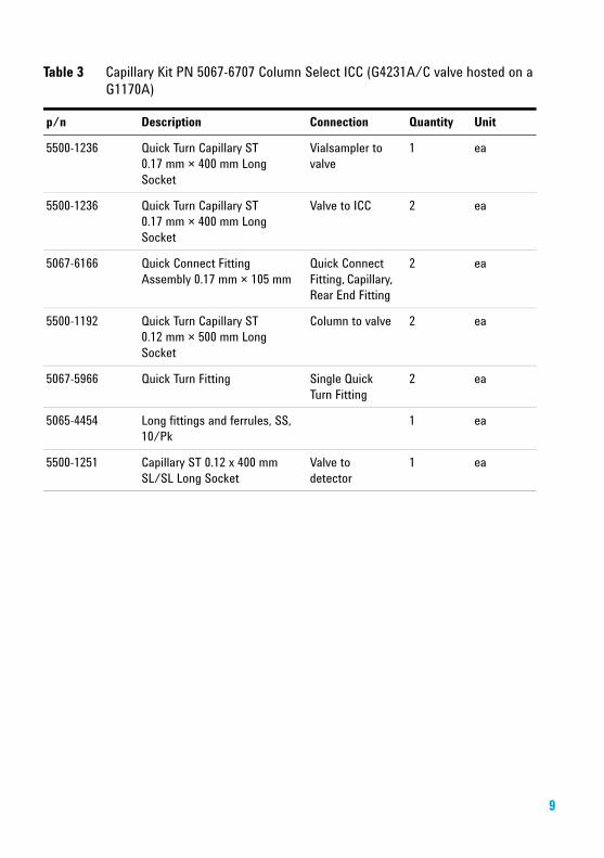
Table 3 Capillary Kit PN 5067-6707 Column Select ICC (G4231A/C valve hosted on a G1170A)
p/n Description Connection Quantity Unit
5500-1236 Quick Turn Capillary ST 0.17 mm × 400 mm Long Socket
Vialsampler to valve
1 ea
5500-1236 Quick Turn Capillary ST 0.17 mm × 400 mm Long Socket
Valve to ICC 2 ea
5067-6166 Quick Connect Fitting Assembly 0.17 mm × 105 mm
Quick Connect Fitting, Capillary, Rear End Fitting
2 ea
5500-1192 Quick Turn Capillary ST 0.12 mm × 500 mm Long Socket
Column to valve 2 ea
5067-5966 Quick Turn Fitting Single Quick Turn Fitting
2 ea
5065-4454 Long fittings and ferrules, SS, 10/Pk
1 ea
5500-1251 Capillary ST 0.12 x 400 mm SL/SL Long Socket
Valve to detector
1 ea
9
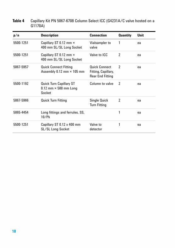
Table 4 Capillary Kit PN 5067-6708 Column Select ICC (G4231A/C valve hosted on a G1170A)
p/n Description Connection Quantity Unit
5500-1251 Capillary ST 0.12 mm × 400 mm SL/SL Long Socket
Vialsampler to valve
1 ea
5500-1251 Capillary ST 0.12 mm × 400 mm SL/SL Long Socket
Valve to ICC 2 ea
5067-5957 Quick Connect Fitting Assembly 0.12 mm × 105 mm
Quick Connect Fitting, Capillary, Rear End Fitting
2 ea
5500-1192 Quick Turn Capillary ST 0.12 mm × 500 mm Long Socket
Column to valve 2 ea
5067-5966 Quick Turn Fitting Single Quick Turn Fitting
2 ea
5065-4454 Long fittings and ferrules, SS, 10/Pk
1 ea
5500-1251 Capillary ST 0.12 x 400 mm SL/SL Long Socket
Valve to detector
1 ea
10
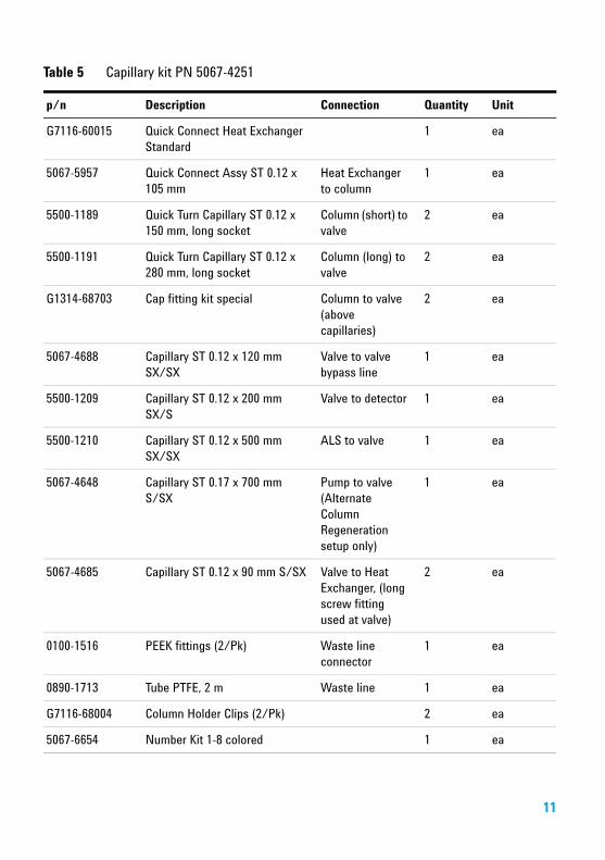
Table 5 Capillary kit PN 5067-4251
p/n Description Connection Quantity Unit
G7116-60015 Quick Connect Heat Exchanger Standard
1 ea
5067-5957 Quick Connect Assy ST 0.12 x 105 mm
Heat Exchanger to column
1 ea
5500-1189 Quick Turn Capillary ST 0.12 x 150 mm, long socket
Column (short) to valve
2 ea
5500-1191 Quick Turn Capillary ST 0.12 x 280 mm, long socket
Column (long) to valve
2 ea
G1314-68703 Cap fitting kit special Column to valve (above capillaries)
2 ea
5067-4688 Capillary ST 0.12 x 120 mm SX/SX
Valve to valve bypass line
1 ea
5500-1209 Capillary ST 0.12 x 200 mm SX/S
Valve to detector 1 ea
5500-1210 Capillary ST 0.12 x 500 mm SX/SX
ALS to valve 1 ea
5067-4648 Capillary ST 0.17 x 700 mm S/SX
Pump to valve (Alternate Column Regeneration setup only)
1 ea
5067-4685 Capillary ST 0.12 x 90 mm S/SX Valve to Heat Exchanger, (long screw fitting used at valve)
2 ea
0100-1516 PEEK fittings (2/Pk) Waste line connector
1 ea
0890-1713 Tube PTFE, 2 m Waste line 1 ea
G7116-68004 Column Holder Clips (2/Pk) 2 ea
5067-6654 Number Kit 1-8 colored 1 ea
11
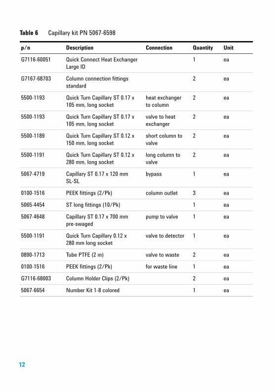
Table 6 Capillary kit PN 5067-6598
p/n Description Connection Quantity Unit
G7116-60051 Quick Connect Heat Exchanger Large ID
1 ea
G7167-68703 Column connection fittings standard
2 ea
5500-1193 Quick Turn Capillary ST 0.17 x 105 mm, long socket
heat exchanger to column
2 ea
5500-1193 Quick Turn Capillary ST 0.17 x 105 mm, long socket
valve to heat exchanger
2 ea
5500-1189 Quick Turn Capillary ST 0.12 x 150 mm, long socket
short column to valve
2 ea
5500-1191 Quick Turn Capillary ST 0.12 x 280 mm, long socket
long column to valve
2 ea
5067-4719 Capillary ST 0.17 x 120 mm SL-SL
bypass 1 ea
0100-1516 PEEK fittings (2/Pk) column outlet 3 ea
5065-4454 ST long fittings (10/Pk) 1 ea
5067-4648 Capillary ST 0.17 x 700 mm pre-swaged
pump to valve 1 ea
5500-1191 Quick Turn Capillary 0.12 x 280 mm long socket
valve to detector 1 ea
0890-1713 Tube PTFE (2 m) valve to waste 2 ea
0100-1516 PEEK fittings (2/Pk) for waste line 1 ea
G7116-68003 Column Holder Clips (2/Pk) 2 ea
5067-6654 Number Kit 1-8 colored 1 ea
12
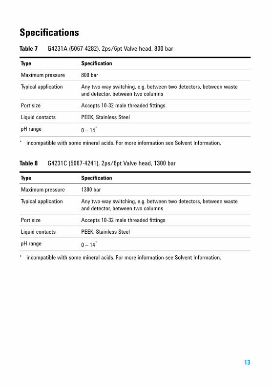
SpecificationsTable 7 G4231A (5067-4282), 2ps/6pt Valve head, 800 bar
Type Specification
Maximum pressure 800 bar
Typical application Any two-way switching, e.g. between two detectors, between waste and detector, between two columns
Port size Accepts 10-32 male threaded fittings
Liquid contacts PEEK, Stainless Steel
pH range 0 – 14*
* incompatible with some mineral acids. For more information see Solvent Information.
Table 8 G4231C (5067-4241), 2ps/6pt Valve head, 1300 bar
Type Specification
Maximum pressure 1300 bar
Typical application Any two-way switching, e.g. between two detectors, between waste and detector, between two columns
Port size Accepts 10-32 male threaded fittings
Liquid contacts PEEK, Stainless Steel
pH range 0 – 14*
* incompatible with some mineral acids. For more information see Solvent Information.
13
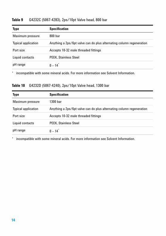
Table 9 G4232C (5067-4283), 2ps/10pt Valve head, 800 bar
Type Specification
Maximum pressure 800 bar
Typical application Anything a 2ps/6pt valve can do plus alternating column regeneration
Port size Accepts 10-32 male threaded fittings
Liquid contacts PEEK, Stainless Steel
pH range 0 – 14*
* incompatible with some mineral acids. For more information see Solvent Information.
Table 10 G4232D (5067-4240), 2ps/10pt Valve head, 1300 bar
Type Specification
Maximum pressure 1300 bar
Typical application Anything a 2ps/6pt valve can do plus alternating column regeneration
Port size Accepts 10-32 male threaded fittings
Liquid contacts PEEK, Stainless Steel
pH range 0 – 14*
* incompatible with some mineral acids. For more information see Solvent Information.
14
InstallationInstallation of the Valve HeadsThe valve drives are factory-installed in the Multicolumn Thermostat. The valve heads are interchangeable and can be easily mounted.
At the first installation, the transportation lock and the dummy valve have to be removed, see “Remove the Transportation Lock and the Valve Dummy” on page 15. The valve heads can be installed by mounting the valve heads onto the valve drives and fastening the nut manually (do not use any tools).
Be sure that the guide pin snaps into the groove of the valve drive thread.
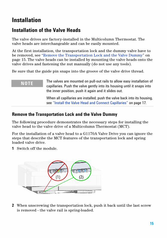
Remove the Transportation Lock and the Valve DummyThe following procedure demonstrates the necessary steps for installing the valve head to the valve drive of a Multicolumn Thermostat (MCT).
For the installation of a valve head to a G1170A Valve Drive you can ignore the steps that describe the MCT features of the transportation lock and spring loaded valve drive.
1 Switch off the module.
2 When unscrewing the transportation lock, push it back until the last screw is removed - the valve rail is spring-loaded.
NOTE The valves are mounted on pull-out rails to allow easy installation of capillaries. Push the valve gently into its housing until it snaps into the inner position, push it again and it slides out.
When all capillaries are installed, push the valve back into its housing, see “Install the Valve Head and Connect Capillaries” on page 17.
15

3 Press on the valve dummy (1.) to release it (2.) (spring-loaded valve rail).
4
5
16
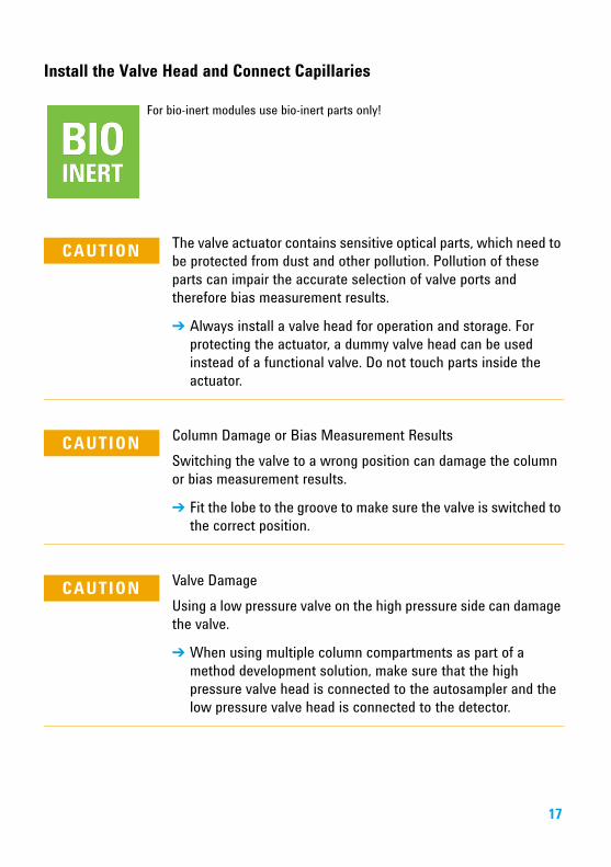
Install the Valve Head and Connect Capillaries
For bio-inert modules use bio-inert parts only!
CAUTION The valve actuator contains sensitive optical parts, which need to be protected from dust and other pollution. Pollution of these parts can impair the accurate selection of valve ports and therefore bias measurement results.
➔ Always install a valve head for operation and storage. For protecting the actuator, a dummy valve head can be used instead of a functional valve. Do not touch parts inside the actuator.
CAUTION Column Damage or Bias Measurement ResultsSwitching the valve to a wrong position can damage the column or bias measurement results.
➔ Fit the lobe to the groove to make sure the valve is switched to the correct position.
CAUTION Valve DamageUsing a low pressure valve on the high pressure side can damage the valve.
➔ When using multiple column compartments as part of a method development solution, make sure that the high pressure valve head is connected to the autosampler and the low pressure valve head is connected to the detector.
17
18
CAUTION Sample degradation and contamination of the instrumentMetal parts in the flow path can interact with the bio-molecules in the sample leading to sample degradation and contamination.
➔ For bio-inert applications, always use dedicated bio-inert parts, which can be identified by the bio-inert symbol or other markers described in this manual.
➔ Do not mix bio-inert and non-inert modules or parts in a bio-inert system.
CAUTION Wrong combination of fitting with valveThe InfinityLab Quick Turn Fitting (5067-5966) is not compatible with the G5639A Bio-inert 4-Column Selector Valve. Misuse can lead to extra dead volume and leaks.
➔ As fitting, use UHP fitting (5067-5403) instead.
NOTE For information about the compatibility mode of 800 bar valve heads see Information on RFID Tag Technical Note (01200-90134).
NOTE For a correct installation of the valve head, the outside pin (red) must completely fit into the outside groove on the valve drive’s shaft (red). A correct installation is only possible if the two pins (green and blue) on the valve head fit into their corresponding grooves on the valve drive’s actuator axis. Their match depends on the diameter of the pin and groove.
NOTE The tag reader reads the valve head properties from the valve head RFID tag during initialization of the module. Valve properties will not be updated, if the valve head is replaced while the module is on. Selection of valve port positions can fail, if the instrument does not know the properties of the installed valve.
NOTE To allow correct valve identification, power off the valve drive for at least 10 s.
NOTE For firmware requirements see Information on new RFID Tag Assembly Version Technical Note (01200-90133) which is included to each valve head.
19
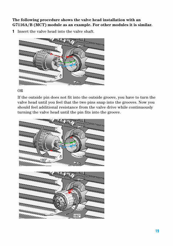
The following procedure shows the valve head installation with an G7116A/B (MCT) module as an example. For other modules it is similar.
1 Insert the valve head into the valve shaft.
OR
If the outside pin does not fit into the outside groove, you have to turn the valve head until you feel that the two pins snap into the grooves. Now you should feel additional resistance from the valve drive while continuously turning the valve head until the pin fits into the groove.

20
2 When the outer pin is locked into the groove, manually screw the nut onto the valve head.
NOTEFasten the nut manually. Do not use any tools.
3 Install all required capillary connections to the valve.
4 Push the valve head until it snaps in and stays in the rear position.
5 Power on or power-cycle your module, so the valve head gets recognized during module initialization.
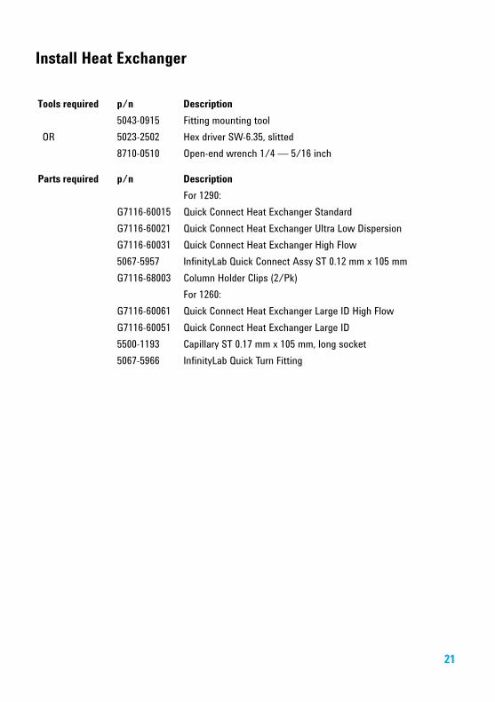
Install Heat Exchanger
Tools required p/n Description
5043-0915 Fitting mounting toolOR 5023-2502 Hex driver SW-6.35, slitted
8710-0510 Open-end wrench 1/4 — 5/16 inch
Parts required p/n Description
For 1290:G7116-60015 Quick Connect Heat Exchanger StandardG7116-60021 Quick Connect Heat Exchanger Ultra Low DispersionG7116-60031 Quick Connect Heat Exchanger High Flow5067-5957 InfinityLab Quick Connect Assy ST 0.12 mm x 105 mmG7116-68003 Column Holder Clips (2/Pk)
For 1260:G7116-60061 Quick Connect Heat Exchanger Large ID High FlowG7116-60051 Quick Connect Heat Exchanger Large ID5500-1193 Capillary ST 0.17 mm x 105 mm, long socket5067-5966 InfinityLab Quick Turn Fitting
21
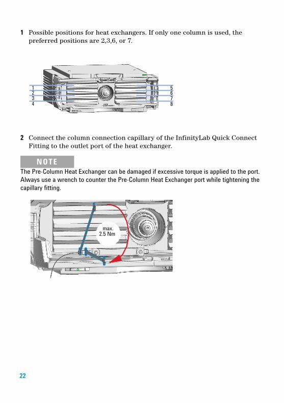
1 Possible positions for heat exchangers. If only one column is used, the preferred positions are 2,3,6, or 7.
2 Connect the column connection capillary of the InfinityLab Quick Connect Fitting to the outlet port of the heat exchanger.
NOTEThe Pre-Column Heat Exchanger can be damaged if excessive torque is applied to the port. Always use a wrench to counter the Pre-Column Heat Exchanger port while tightening the capillary fitting.
22
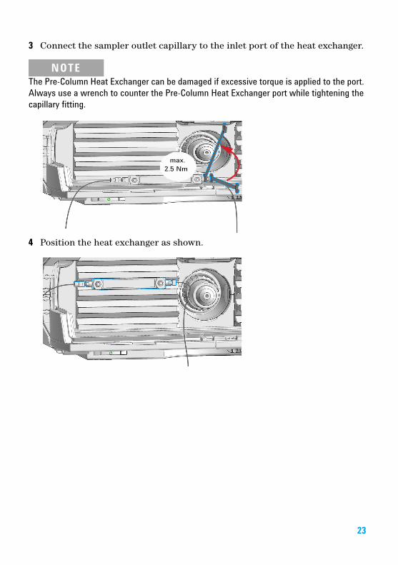
3 Connect the sampler outlet capillary to the inlet port of the heat exchanger.
NOTEThe Pre-Column Heat Exchanger can be damaged if excessive torque is applied to the port. Always use a wrench to counter the Pre-Column Heat Exchanger port while tightening the capillary fitting.
4 Position the heat exchanger as shown.
23
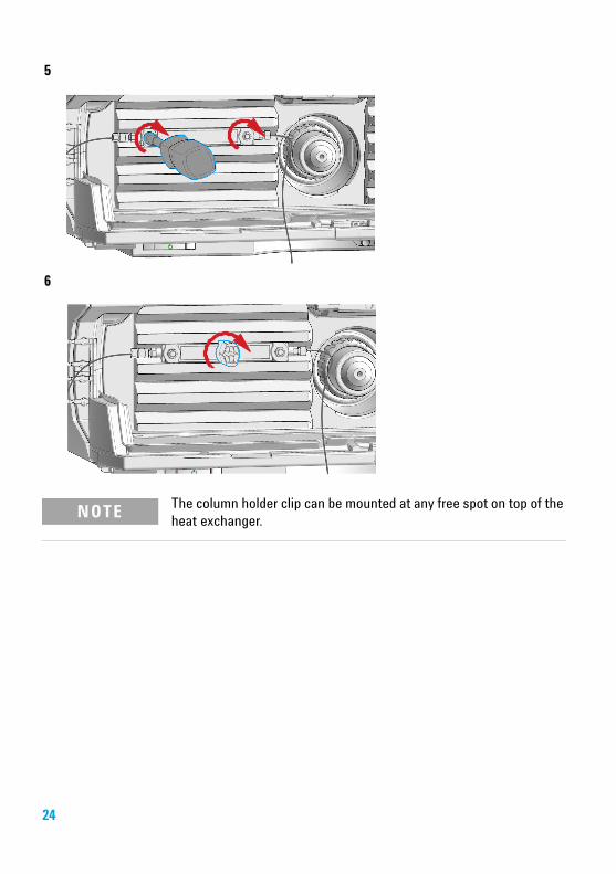
5
6
NOTE The column holder clip can be mounted at any free spot on top of the heat exchanger.
24

Install the CapillariesThe 2ps/10pt valve can be used here in the same way as a 2ps/6pt valve; just follow the re-routing diagram below.
Map the ports from the 2ps/6pt valve to the corresponding ports of the 2ps/10pt valve according to the red arrows. For example, mount the capillary connected to port 6 (2ps/6pt) at port 2 instead.
Connect port 1 and port 8 with a 120 mm length capillary. Plug plastic fittings into ports 9 and 10.
Figure 1 Re-routing of 2 position/10 port valve to match 2 position/6 port valve
1 Install the capillaries.
2 Connect the capillaries connected directly to a column and fasten them immediately with a spanner.
3 Finger-tighten all remaining capillaries.
4 Clip the unions into the corresponding clips of the low dispersion heat exchangers.
5 Fasten all fittings with a spanner.
NOTE Use outmost care to avoid any void volumes caused by poor connections.
NOTE Use outmost care to avoid any void volumes caused by poor connections.
25
6 Starting from position one through six (ten, respectively), fasten the fittings on the heat exchanger.
7 Fasten all fittings on attached modules (autosampler, detector, additional pumps). Fit all unused valve ports with a plastic plug.
8 Push the valves into the rear positions.
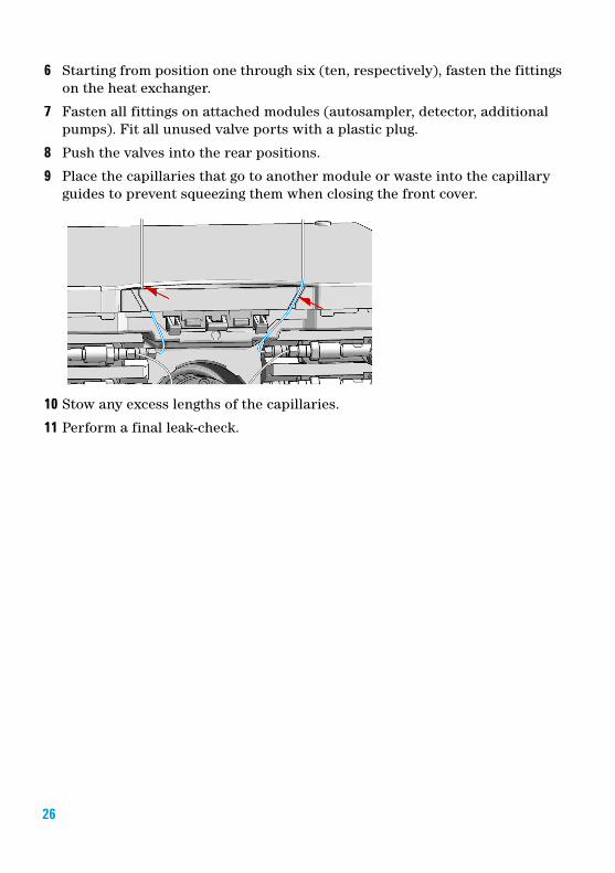
9 Place the capillaries that go to another module or waste into the capillary guides to prevent squeezing them when closing the front cover.
10 Stow any excess lengths of the capillaries.
11 Perform a final leak-check.
26
Valve Parts
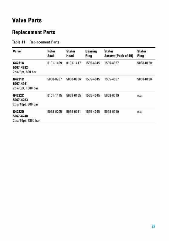
Replacement PartsTable 11 Replacement Parts
Valve Rotor Seal
Stator Head
Bearing Ring
Stator Screws(Pack of 10)
Stator Ring
G4231A5067-42822ps/6pt, 800 bar
0101-1409 0101-1417 1535-4045 1535-4857 5068-0120
G4231C5067-42412ps/6pt, 1300 bar
5068-0207 5068-0006 1535-4045 1535-4857 5068-0120
G4232C5067-4283 2ps/10pt, 800 bar
0101-1415 5068-0165 1535-4045 5068-0019 n.a.
G4232D5067-42402ps/10pt, 1300 bar
5068-0205 5068-0011 1535-4045 5068-0019 n.a.
27
Valve Head Parts
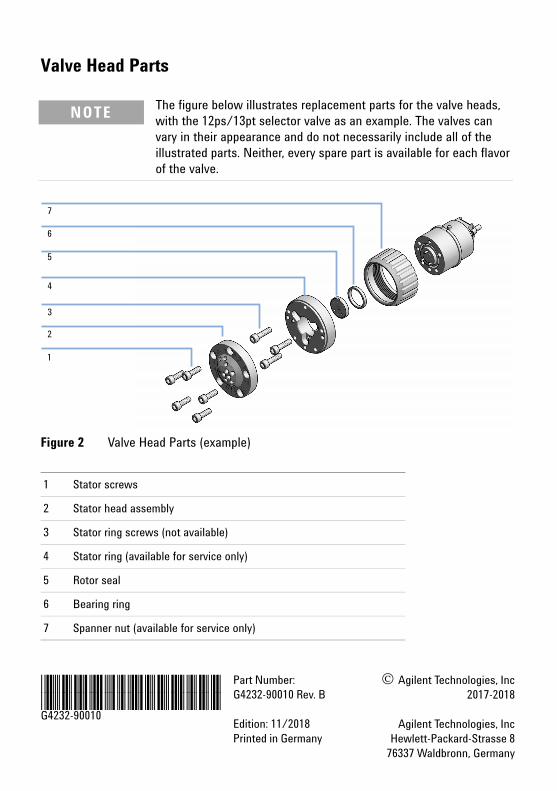
Figure 2 Valve Head Parts (example)
NOTE The figure below illustrates replacement parts for the valve heads, with the 12ps/13pt selector valve as an example. The valves can vary in their appearance and do not necessarily include all of the illustrated parts. Neither, every spare part is available for each flavor of the valve.
1 Stator screws
2 Stator head assembly
3 Stator ring screws (not available)
4 Stator ring (available for service only)
5 Rotor seal
6 Bearing ring
7 Spanner nut (available for service only)
*G4232-90010**G4232-90010*G4232-90010
Part Number:G4232-90010 Rev. B
Edition: 11/2018Printed in Germany
© Agilent Technologies, Inc2017-2018
Agilent Technologies, IncHewlett-Packard-Strasse 8
76337 Waldbronn, Germany