
Agilent InfinityLab Quick Change Valve G4237A Instructions€¦ · Agilent InfinityLab Quick Change...
16
Agilent Technologies Agilent InfinityLab Quick Change Valve G4237A Instructions This technical note describes the installation and application of the Agilent InfinityLab Quick Change 4 column selector Valve Head G4237A in a 1260/1290 Infinity II Multicolumn Thermostat (MCT). Contents Typical Applications 2 Multicolumn Selection 2 Method Development 3 Delivery Checklist 3 Install the Valve Heads 6 Remove the Transportation Lock and the Valve Dummy 6 Install the Valve Head and Connect Capillaries 8 Install the Capillaries 12 Setup Examples 14 Valve Specifications 15 Valve Parts 15
Transcript of Agilent InfinityLab Quick Change Valve G4237A Instructions€¦ · Agilent InfinityLab Quick Change...

Agilent InfinityLab Quick Change Valve G4237A Instructions
This technical note describes the installation and application of the Agilent InfinityLab Quick Change 4 column selector Valve Head G4237A in a 1260/1290 Infinity II Multicolumn Thermostat (MCT).
Contents
Typical Applications 2Multicolumn Selection 2Method Development 3
Delivery Checklist 3
Install the Valve Heads 6Remove the Transportation Lock and the Valve Dummy 6Install the Valve Head and Connect Capillaries 8
Install the Capillaries 12
Setup Examples 14
Valve Specifications 15
Valve Parts 15
Agilent Technologies
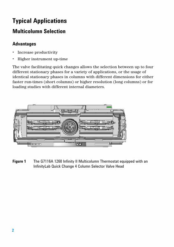
Typical ApplicationsMulticolumn Selection
Advantages• Increase productivity
• Higher instrument up-time
The valve facilitating quick changes allows the selection between up to four different stationary phases for a variety of applications, or the usage of identical stationary phases in columns with different dimensions for either faster run-times (short columns) or higher resolution (long columns) or for loading studies with different internal diameters.
Figure 1 The G7116A 1260 Infinity II Multicolumn Thermostat equipped with an InfinityLab Quick Change 4 Column Selector Valve Head
2

Method Development
Advantages:• Faster method development
• Automated method development possible
Figure 2 Totally different chromatographic results by using the same sample but three different stationary phases
Delivery ChecklistCheck the content of the delivery. You should have received the following:
G4237A:
p/n Description
5067-4279 4 column selector valve head, 800 bar
5067-6596 Cap kit 0.12 mm, 4-col, incl. QC-HE(Optional)
5067-4300 Cap kit 0.17 mm, 4-col, incl. QC-HE(Optional)
3

The different Capillary Kits for the 4-Column Selector contain the following parts:
Capillary Kit (5067-6596)
# p/n Description
4 G7116-60015 Quick Connect Heat Exchanger Standard
4 G7116-68003 Column Holder Clips (2/Pk)
1 5500-1202 Capillary ST 0.12 mm x 500 mm M4-SL PS-PSautosampler to valve
4 5500-1199 Capillary ST 0.12 mm x 130 mm M4-SL PS-PSvalve to heat exchanger
4 5500-1200 Quick Turn Capillary ST 0.12 mm x 130 mm SL/Mcolumn to valve
1 5063-6591 PEEK Fittings 10/PKcolumn outlet
4 5500-1201 Capillary ST 0.12 mm x 105 mm SL-- PS-LSheat exchanger (PS-SL) to column
1 5500-1203 Capillary ST 0.12 mm x 280 mm M4-SL PS-PSvalve to detector
1 5500-1204 Capillary ST 0.12 mm x 150 mm M4-M4 PS-PSvalve to valve (column bypass)
8 G1314-68703 Cap fitting kit special
1 5023-2504 Hex driver SW-4 slitted
1 5067-6141 M4 Blank nut
1 G1375-87326 Waste tube
1 5067-6654 Number Kit 1-8 colored
4

5
Capillary Kit (5067-4300)
Capillary and Fitting Information• M4 = fitting thread size for micro valve ports• PS = pre-swaged fitting• NS = non-swaged fitting• SL = fitting screw long• LS = long capillary socket (required for special fittings as the A-Line Quick
Turn Fittings)• SV = removable high pressure fitting
# p/n Description
4 G7116-60051 Quick-Connect Heat Exchanger Large ID
4 G7116-68003 Column Holder Clips (2/Pk)
1 5067-6188 Capillary ST 0.17 mm x 500 mm SL-M4 PS-PSautosampler to valve
4 5067-5109 Capillary ST 0.17 mm x 90 mm SL/Mvalve to heat exchanger
4 5067-4746 Capillary ST 0.12 mm x 250 mm SLV/Mlong column to valve
4 5500-1200 Quick Turn Capillary ST 0.12 mm x 130 mm SL/Mshort column to valve
2 0100-1516 Fingertight fitting PEEK, 2/pkcolumn outlet
4 5500-1193 Capillary ST 0.17 mm x 105 mm, long socketheat exchanger to column
1 5500-1203 Capillary ST 0.12 mm x 280 mm M4-SL PS-PSvalve to detector
1 5500-1204 Capillary ST 0.12 mm x 150 mm M4-M4 PS-PSvalve to valve (column bypass)
1 5065-4454 Fitting screw long10/pk
1 5023-2504 Hex driver SW-4 slitted
1 5067-6141 M4 Blank nut
1 G1375-87326 Waste tube
2 G1314-68703 Cap fitting kit special
1 5067-6654 Number Kit 1-8 colored
Install the Valve HeadsThe valve drives are factory-installed in the Multicolumn Thermostat. The valve heads are interchangeable and can be easily mounted.
At the first installation, the transportation lock and the dummy valve have to be removed, see “Remove the Transportation Lock and the Valve Dummy” on page 6. The valve heads can be installed by mounting the valve heads onto the valve drives and fastening the nut manually (do not use any tools).
Be sure that the guide pin snaps into the groove of the valve drive thread.
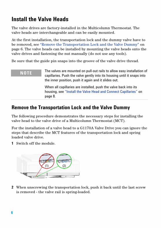
Remove the Transportation Lock and the Valve DummyThe following procedure demonstrates the necessary steps for installing the valve head to the valve drive of a Multicolumn Thermostat (MCT).
For the installation of a valve head to a G1170A Valve Drive you can ignore the steps that describe the MCT features of the transportation lock and spring loaded valve drive.
1 Switch off the module.
2 When unscrewing the transportation lock, push it back until the last screw is removed - the valve rail is spring-loaded.
NOTE The valves are mounted on pull-out rails to allow easy installation of capillaries. Push the valve gently into its housing until it snaps into the inner position, push it again and it slides out.
When all capillaries are installed, push the valve back into its housing, see “Install the Valve Head and Connect Capillaries” on page 8.
6

3 Press on the valve dummy (1.) to release it (2.) (spring-loaded valve rail).
4
5
7

Install the Valve Head and Connect Capillaries
For bio-inert modules use bio-inert parts only!
CAUTION The valve actuator contains sensitive optical parts, which need to be protected from dust and other pollution. Pollution of these parts can impair the accurate selection of valve ports and therefore bias measurement results.
➔ Always install a valve head for operation and storage. For protecting the actuator, a dummy valve head can be used instead of a functional valve. Do not touch parts inside the actuator.
CAUTION Column Damage or Bias Measurement ResultsSwitching the valve to a wrong position can damage the column or bias measurement results.
➔ Fit the lobe to the groove to make sure the valve is switched to the correct position.
CAUTION Valve DamageUsing a low pressure valve on the high pressure side can damage the valve.
➔ When using multiple column compartments as part of a method development solution, make sure that the high pressure valve head is connected to the autosampler and the low pressure valve head is connected to the detector.
8

9
CAUTION Sample degradation and contamination of the instrumentMetal parts in the flow path can interact with the bio-molecules in the sample leading to sample degradation and contamination.
➔ For bio-inert applications, always use dedicated bio-inert parts, which can be identified by the bio-inert symbol or other markers described in this manual.
➔ Do not mix bio-inert and non-inert modules or parts in a bio-inert system.
CAUTION Wrong combination of fitting with valveThe InfinityLab Quick Turn fitting (5067-5966) is not compatible with the G5639A Bio-inert 4-Column Selector Valve. Misuse can lead to extra dead volume and leaks.
➔ As fitting, use UHP fitting (5067-5403) instead.
NOTE For information about the compatibility mode of 800 bar valve heads see Information on RFID Tag Technical Note (01200-90134).
NOTE For a correct installation of the valve head, the outside pin (red) must completely fit into the outside groove on the valve drive’s shaft (red). A correct installation is only possible if the two pins (green and blue) on the valve head fit into their corresponding grooves on the valve drive’s actuator axis. Their match depends on the diameter of the pin and groove.
NOTE The tag reader reads the valve head properties from the valve head RFID tag during initialization of the module. Valve properties will not be updated, if the valve head is replaced while the module is on. Selection of valve port positions can fail, if the instrument does not know the properties of the installed valve.
NOTE To allow correct valve identification, power off the valve drive for at least 10 s.
NOTE For firmware requirements see Information on new RFID Tag Assembly Version Technical Note (01200-90133) which is included to each valve head.

The following procedure shows the valve head installation with an G7116A/B (MCT) module as an example. For other modules it is similar.
1 Insert the valve head into the valve shaft.
OR
If the outside pin does not fit into the outside groove, you have to turn the valve head until you feel that the two pins snap into the grooves. Now you should feel additional resistance from the valve drive while continuously turning the valve head until the pin fits into the groove.
10

2 When the outer pin is locked into the groove, manually screw the nut onto the valve head.
NOTEFasten the nut manually. Do not use any tools.
3 Install all required capillary connections to the valve.
4 Push the valve head until it snaps in and stays in the rear position.
5 Power on or power-cycle your module, so the valve head gets recognized during module initialization.
11

12
Install the Capillaries
1 Install the In and Out connectors.• from sampler to the valve ( Capillary ST 0.12 mm x 500 mm M4-SL PS-PS
(5500-1202)) or on a standard system (with 0.17 mm capillaries) Capillary ST 0.17 mm x 500 mm SL-M4 PS-PS (5067-6188)
• from valve to the detector ( Capillary ST 0.12 mm x 280 mm M4-SL PS-PS (5500-1203))
The In port is hydraulically connected to the column inlet ports 1-4 while the Out port connects to the column outlet ports 1`-4`.
CAUTION Damage to the rotor sealInstant pressure release within the valve will lead to water jet effects that can harm internal parts of the valve. This pressure release typically happens if the valve gets switched under high pressure over unused or open channels.➔ Block all unused channels properly with the M4 blank nut.
NOTE To minimize valve movement over open connections it is recommended to plumb the column connected channels in one row.e.g.:• channel 1 – column 1• channel 2 – column 2• channel 3 – blocked• channel 4 – waste
NOTE The blank nuts are only required for the ports on the inner circle that connect the valve with the column inlet.

2 Install the column inlet and outlet connections.
• - ports 1-4 for connections from valve to the heat exchanger ( Capillary ST 0.12 mm x 130 mm M4-SL PS-PS (5500-1199)) or on a standard system (with 0.17 mm capillaries) Capillary ST 0.17 mm x 90 mm SL/M (5067-5109) or waste line (Waste tube (G1375-87326))
• - ports 1`-4` for connections from column outlet to valve, use fingertight PEEK fittings for connecting the column outlet.
For a short column: use Quick Turn Capillary ST 0.12 mm x 130 mm SL/M (5500-1200)
For a long column: use Capillary ST 0.12 mm x 250 mm SLV/M (5067-4746)
13

Setup Examples1 1-4 column-selection
Figure 3 Hydraulic flow path schematics for a 4-column selection setup
2 Two column selection with purge line and valve-bypass
Figure 4 Hydraulic flow path schematics for 2-column selection setup with purge and valve bypass line
14

Valve Specifications
Valve Parts
Replacement Parts
Table 1 G4237A (5067-4279), 4ps/10pt, 4-column selector, 800 bar
Type Specification
Maximum pressure 800 bar
Typical application 4 column selection
Port size Accepts M4 male threaded fittings
Liquid contacts PEEK, Stainless Steel
pH range 0 – 14*
* incompatible with some mineral acids. For more information see Solvent Information.
Table 2 Replacement Parts
Valve Rotor Seal
Stator Head
Bearing Ring
Stator Screws (Pack of 10)
Stator Ring
4 column selector valve head, 800 bar (5067-4279)
5068-0264 5068-0263 1535-4045 5068-0019 n.a.
15

Valve Head Parts
Figure 5 Valve Head Parts (example)
NOTE The figure below illustrates replacement parts for the valve heads, with the 12ps/13pt Selector valve as an example. The valves can vary in their appearance and do not necessarily include all of the illustrated parts. Neither, every spare part is available for each flavor of the valve.
1 Stator screws
2 Stator head assembly
3 Stator ring screws (not available)
4 Stator ring (available for service only)
5 Rotor seal
6 Bearing ring
7 Spanner nut (available for service only)
*G4237-90010**G4237-90010*G4237-90010
Part Number:G4237-90010 Rev. B
Edition: 10/2018Printed in Germany
© Agilent Technologies, Inc2016-2018
Agilent Technologies, IncHewlett-Packard-Strasse 8
76337 Waldbronn, Germany