Heated Valve Box Kits - Agilent Valve... · 3 Agilent G1580A, G1581A, and 19238A/B Heated Valve Box...
20
Agilent Technologies Agilent G1580A, G1581A, and 19238A/B Heated Valve Box Kits 4890, 5890, and 6890 Gas Chromatographs Installation Guide
Transcript of Heated Valve Box Kits - Agilent Valve... · 3 Agilent G1580A, G1581A, and 19238A/B Heated Valve Box...

Agilent G1580A, G1581A, and 19238A/B Heated Valve Box Kits
4890, 5890, and 6890Gas Chromatographs
Installation Guide
Agilent Technologies

Notices© Agilent Technologies, Inc. 2002
No part of this manual may be reproduced in any form or by any means (including elec-tronic storage and retrieval or translation into a foreign language) without prior agree-ment and written consent from Agilent Technologies, Inc. as governed by United States and international copyright laws.
Manual Part Number19238-90117
EditionFirst edition, August 2002
Printed in USA
Agilent Technologies, Inc.2850 Centerville Road Wilmington, DE 19808-1610 USA
Safety Notices
CAUTION
A CAUTION notice denotes a haz-ard. It calls attention to an operat-ing procedure, practice, or the like that, if not correctly performed or adhered to, could result in damage to the product or loss of important data. Do not proceed beyond a CAUTION notice until the indicated conditions are fully understood and met.
WARNING
A WARNING notice denotes a hazard. It calls attention to an operating procedure, practice, or the like that, if not correctly per-formed or adhered to, could result in personal injury or death. Do not proceed beyond a WARNING notice until the indicated condi-tions are fully understood and met.
2 Installation Guide
Agilent G1580A, G1581A, and 19238A/B Heated Valve Box KitsInstallation Guide
Installing the G1580A, G1581A, and 19238A/B Heated Valve Box Kits
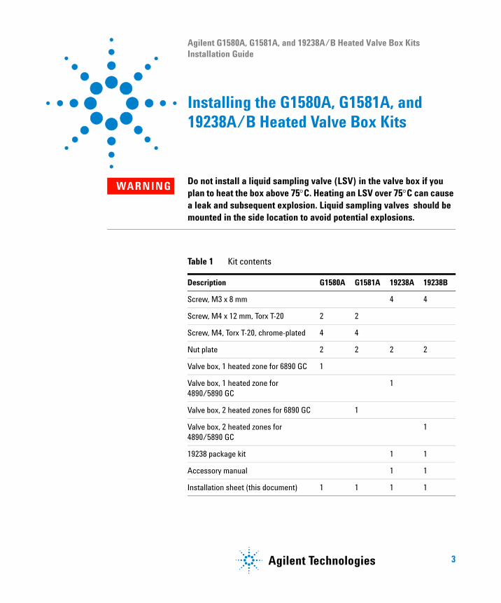
WARNING Do not install a liquid sampling valve (LSV) in the valve box if you plan to heat the box above 75°C. Heating an LSV over 75°C can cause a leak and subsequent explosion. Liquid sampling valves should be mounted in the side location to avoid potential explosions.
Table 1 Kit contents
Description G1580A G1581A 19238A 19238B
Screw, M3 x 8 mm 4 4
Screw, M4 x 12 mm, Torx T-20 2 2
Screw, M4, Torx T-20, chrome-plated 4 4
Nut plate 2 2 2 2
Valve box, 1 heated zone for 6890 GC 1
Valve box, 1 heated zone for 4890/5890 GC
1
Valve box, 2 heated zones for 6890 GC 1
Valve box, 2 heated zones for 4890/5890 GC
1
19238 package kit 1 1
Accessory manual 1 1
Installation sheet (this document) 1 1 1 1
3Agilent Technologies
4
Installing the G1580A, G1581A, and 19238A/B Heated Valve Box Kits
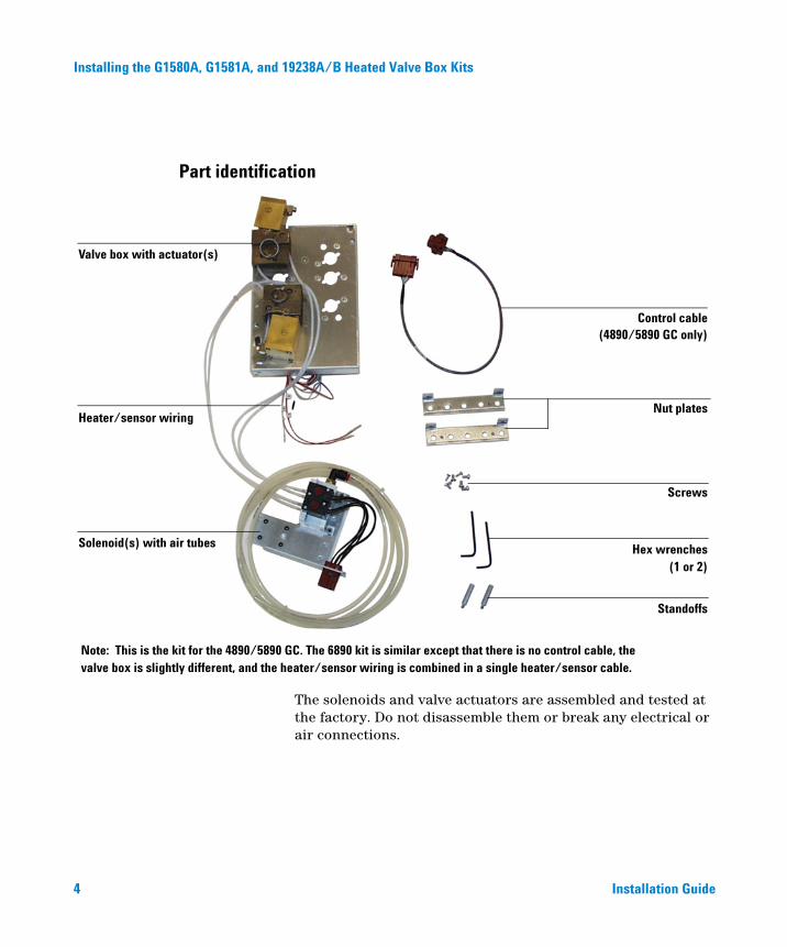
Part identification
Screws
Hex wrenches
Standoffs
Nut plates
Control cable
Valve box with actuator(s)
Solenoid(s) with air tubes
Heater/sensor wiring
Note: This is the kit for the 4890/5890 GC. The 6890 kit is similar except that there is no control cable, thevalve box is slightly different, and the heater/sensor wiring is combined in a single heater/sensor cable.
(1 or 2)
(4890/5890 GC only)
The solenoids and valve actuators are assembled and tested at the factory. Do not disassemble them or break any electrical or air connections.
Installation Guide
Installing the G1580A, G1581A, and 19238A/B Heated Valve Box Kits
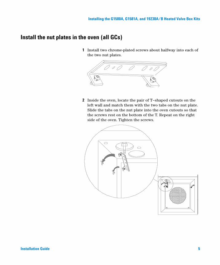
Install the nut plates in the oven (all GCs)
Installation Guide
1 Install two chrome-plated screws about halfway into each of the two nut plates.
2 Inside the oven, locate the pair of T–shaped cutouts on the left wall and match them with the two tabs on the nut plate. Slide the tabs on the nut plate into the oven cutouts so that the screws rest on the bottom of the T. Repeat on the right side of the oven. Tighten the screws.
5

Installing the G1580A, G1581A, and 19238A/B Heated Valve Box Kits
Install the valve box (4890 or 5890 GC)
6
1 Remove the blank cover plate from the valve box mounting location. In some instruments, the cover must be cut out.
??? ????Cut here
Cut here
2 Remove the pre-cut insulation under the plate.
3 Remove the two diagonally opposite screws in the valve box assembly and separate the top and bottom parts.
Installation Guide

Installing the G1580A, G1581A, and 19238A/B Heated Valve Box Kits
Installation Guide
4 Place the bottom part in the mounting location with the heater/sensor leads to the rear. Check that the heater and sensor are fully inserted into the heater block. Secure with standoffs in diagonally opposite corners.
Standoffs
5 Place the top part on the bottom part and secure with the two screws removed previously.
7
Installing the G1580A, G1581A, and 19238A/B Heated Valve Box Kits
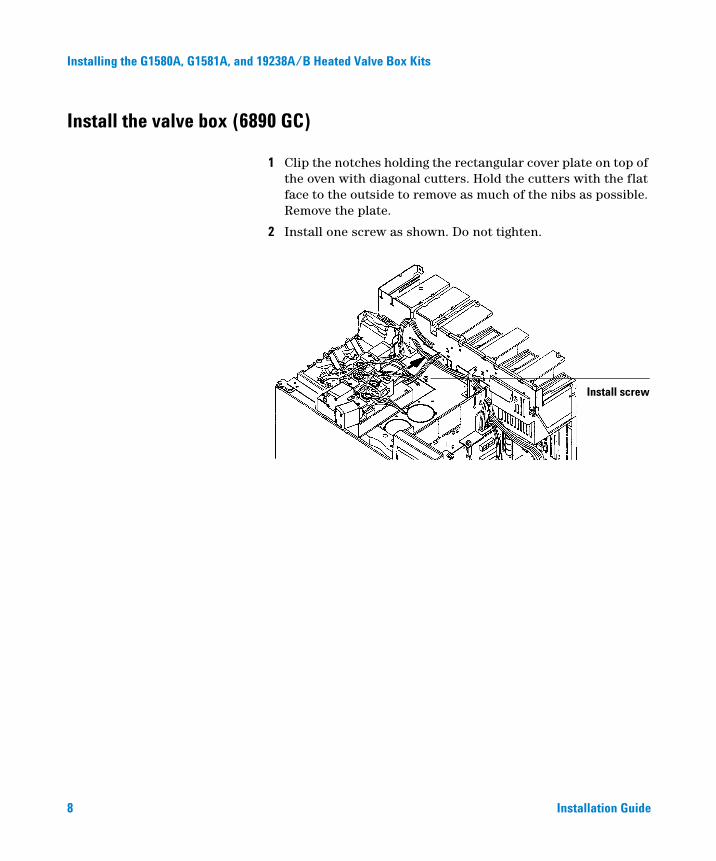
Install the valve box (6890 GC)
8
1 Clip the notches holding the rectangular cover plate on top of the oven with diagonal cutters. Hold the cutters with the flat face to the outside to remove as much of the nibs as possible. Remove the plate.
2 Install one screw as shown. Do not tighten.
Install screw
Installation Guide
Installing the G1580A, G1581A, and 19238A/B Heated Valve Box Kits
Installation Guide
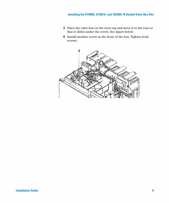
3 Place the valve box on the oven top and move it to the rear so that it slides under the screw. See figure below.
4 Install another screw at the front of the box. Tighten both screws.
9

Installing the G1580A, G1581A, and 19238A/B Heated Valve Box Kits
Make air and electric connections (4890 or 5890 GC)
Install and wire the solenoids
10
1 Mount the solenoid valve assembly behind the oven (see next figure).
• 5890A: Secure the solenoid valve assembly and ground wire to the GC with four M3 screws.
• 4890 and 5890 SERIES II: Secure the solenoid valve assembly and ground wire to the GC with three M4 screws.
4890 and 5890 SERIES II
5890A
2 Uncoil the air supply line and route it through the slot on the left side of the GC near the rear of the oven.
Installation Guide
Installing the G1580A, G1581A, and 19238A/B Heated Valve Box Kits
Installation Guide
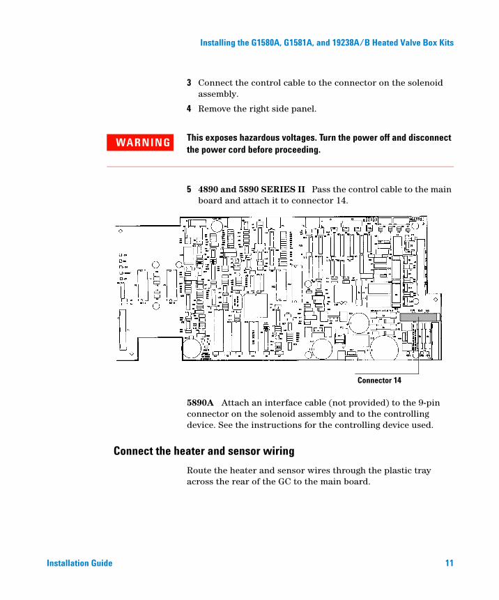
3 Connect the control cable to the connector on the solenoid assembly.
4 Remove the right side panel.
WARNING This exposes hazardous voltages. Turn the power off and disconnect the power cord before proceeding.
5 4890 and 5890 SERIES II Pass the control cable to the main board and attach it to connector 14.
Connector 14
5890A Attach an interface cable (not provided) to the 9-pin connector on the solenoid assembly and to the controlling device. See the instructions for the controlling device used.
Connect the heater and sensor wiring
Route the heater and sensor wires through the plastic tray across the rear of the GC to the main board.
11

Installing the G1580A, G1581A, and 19238A/B Heated Valve Box Kits
4890 and 5890 SERIES II
12
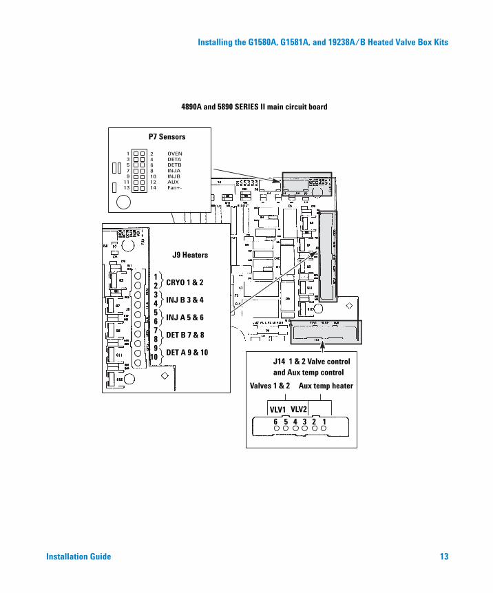
We recommend using the AUX heater connections on connector J14 and the AUX sensor connections on connector P7. If they are already in use, any matched pair of connections on J9 (heaters) and P7 (sensors) may be used.
Connect the sensor leads (white) to P7. Connect the heater leads (red) to the corresponding connections on either J14 (recommended) or J9.
Installation Guide
Installing the G1580A, G1581A, and 19238A/B Heated Valve Box Kits
Installation Guide
?????
????
?
?
?
?
?
?
?
?
?
??????
13579
1113
2468101214
OVENDETADETBINJAINJBAUXFan+-
123456789
10
CRYO 1 & 2
INJ B 3 & 4
INJ A 5 & 6
DET B 7 & 8
DET A 9 & 10
P7 Sensors
4890A and 5890 SERIES II main circuit board
J9 Heaters
J14 1 & 2 Valve controland Aux temp control
Valves 1 & 2 Aux temp heater
VLV1 VLV2
123456
13

Installing the G1580A, G1581A, and 19238A/B Heated Valve Box Kits
5890
14
Connect the sensor leads (white) to J7. Connect the heater leads (red) to J9.
J7
Oven 1&2
Det A 3&4
Det B 5&6
Inj A 7&8
Inj B 9&10
STRT 11&12
Door 13&14
5890A Main circuit board
J9 Heaters
Sensors
Cryo 1&2Inj B 3&4Inj A 5&6Det B 7&8Det A 9&10
Installation Guide

Installing the G1580A, G1581A, and 19238A/B Heated Valve Box Kits
Make air and electric connections (6890 GC)
Install and wire the solenoids
Installation Guide
The internal valve wiring is located near the top center of the main board. To access it, you must remove the right side panel.
WARNING Removing the side panel exposes dangerous voltages. Turn the instrument off and disconnect it from its power source before proceeding.
1 Attach the solenoid assembly to the main board as shown.
2 x 8 connector
Tighten 2 screws
Air supply tube
Plug into 2 x 8 connector
Slots
2 Place the tubing and cables in the slots in the chassis just above the solenoids.
15

16
Installing the G1580A, G1581A, and 19238A/B Heated Valve Box Kits
3 Uncoil the air supply tubing and pass it through the hole in the back of the GC (at the bottom of the second ventilation slot).
The connectors are prewired so that the Valve 1 driver controls the solenoid closest to the front of the GC, Valve 2 controls the next one, etc.
A1 V1 V2 V3 V4 A2
To front of GC
2 x 8 connector on main board
Bracket with connectors
Air fittings to actuators
Solenoids (up to 4)
To remove a connector from the bracket, press the locking tabs on the side and pull the connector down. To insert a connector, push it up into a bracket hole until it locks.
Connect the heater/sensor cable
Plug the heater/sensor cable into connector A1 (Aux 1) or connector A2 (Aux 2).
Plumb the actuators
Each valve actuator is driven by two tubes that connect to a solenoid through two connectors on top. These connectors do not require tools.
• To make a connection, push the tubing down into the connector as far as it will go.
Installation Guide
Installing the G1580A, G1581A, and 19238A/B Heated Valve Box Kits
Installation Guide
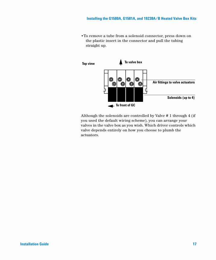
•To remove a tube from a solenoid connector, press down on the plastic insert in the connector and pull the tubing straight up.
Although the solenoids are controlled by Valve # 1 through 4 (if you used the default wiring scheme), you can arrange your valves in the valve box as you wish. Which driver controls which valve depends entirely on how you choose to plumb the actuators.
To valve boxTop view
Air fittings to valve actuators
Solenoids (up to 4)
To front of GC
17

Installing the G1580A, G1581A, and 19238A/B Heated Valve Box Kits
Restore the GC to operating condition
18
1 Re-install any covers that were removed.
2 Plug in the power cord and turn on the GC.
3 6890 GC. Configure the valves. See the GC’s operating instructions if you need help with this step.
4 Connect the solenoid air supply line to a source of clean, dry compressed air at 55 psi. High purity is not required; a clean house air supply is adequate.
5 If your detector also uses air, its operation may be affected by pulses in a shared air line. The solenoid air supply should be separate from the detector air supply.
6 Turn on the air supply to the solenoid valves.
7 Use a flat head screwdriver to turn each valve ON and OFF. Ensure that each valve is physically in the OFF position (full counterclockwise).
8 Use the 3-mm hex key wrench to tighten the link arm lockscrew by rotating it clockwise until very tight.
Hex key wrench
Installation Guide

Installing the G1580A, G1581A, and 19238A/B Heated Valve Box Kits
Installation Guide
19
Agilent Technologies
Agilent Technologies, Inc.
Printed in USA, August 2002
19238-90117