
AfterSales Training - delaraspelle.comdelaraspelle.com/porsche/P10W Sports Car Engine Repair Gen...
54
AfterSales Training Engine Repair – 911/987 (Gen. II) P10W Gen. II ®
Transcript of AfterSales Training - delaraspelle.comdelaraspelle.com/porsche/P10W Sports Car Engine Repair Gen...
AfterSales Training Engine Repair – 911/987 (Gen. II)
P10W Gen. II
®

Porsche AfterSales Training
Student Name: ________________________________________________
Training Center Location: ________________________________________________
Instructor Name: ________________________________________________
Date: ___________________
Important Notice: Some of the contents of this AfterSales Training brochure was originally written by Porsche AG for its rest-of-world English speaking market. The electronic text and graphic files were then imported by Porsche Cars N.A, Inc. and editedfor content. Some equipment and technical data listed in this publication may not be applicable for our market. Specifications aresubject to change without notice.
We have attempted to render the text within this publication to American English as best as we could. We reserve the right tomake changes without notice.
© 2010 Porsche Cars North America, Inc. All Rights Reserved. Reproduction or translation in whole or in part is not permittedwithout written authorization from publisher. AfterSales Training Publications
Dr. Ing. h.c. F. Porsche AG is the owner of numerous trademarks, both registered and unregistered, including without limitationthe Porsche Crest®, Porsche®, Boxster®, Carrera®, Cayenne®, Cayman™, Panamera®, Tiptronic®, VarioCam®, PCM®,911®, 4S®, FOUR, UNCOMPROMISED.SM and the model numbers and distinctive shapes of Porsche's automobiles such as,the federally registered 911 and Boxster automobiles. The third party trademarks contained herein are the properties of theirrespective owners. Specifications, performance standards, options, and other elements shown are subject to change withoutnotice. Some vehicles may be shown with non-U.S. equipment. Porsche recommends seat belt usage and observance of trafficlaws at all times. Printed in the USA
Part Number - PNA P10 WDF 02 Edition - 3/10

Table of Contents
911/987 Gen. II Engine Repair
Description Section
Engine Type Designations . . . . . . . . . . . . . . . . . . . . . . . . . . . . . . . . . . . . . . . . . . . . . . . . . . . . .1
911 Carrera (997) & Boxster/Cayman (987) 2nd Generation . . . . . . . . . . . . . . . . . . . . . . . . . . .2
911 Turbo (997) 2nd Generation . . . . . . . . . . . . . . . . . . . . . . . . . . . . . . . . . . . . . . . . . . . . . . . .3
Additional Notes – Tips For Engine Assembly . . . . . . . . . . . . . . . . . . . . . . . . . . . . . . . . . . . . . . .4
Conversion Charts . . . . . . . . . . . . . . . . . . . . . . . . . . . . . . . . . . . . . . . . . . . . . . . . . . . . . . . . . .5

911/987 Gen. II Engine Repair

Engine Type Designations
911/987 Gen. II Engine Repair Page 1.1
911, Boxster and Cayman Engine Type Designations Since Model Year 1984
Model Engine Displ. Engine Power Installed InYear Type Liters kW / HP *
1984 930.20 3.2 170/231 911 Carrera - RoW930.21 3.2 152/207 911 Carrera - USA/Canada/Japan930.66 3.3 221/300 911 Turbo - Worldwide
1985 930.20 3.2 170/231 911 Carrera - RoW930.21 3.2 152/207 FRG/USA/Canada/Japan (with catalytic converter)930.26 3.2 170/231 Sweden /Switzerland /AustraIia930.66 3.3 221/300 911 Turbo - Worldwide
1986 930.20 3.2 170/231 911 Carrera - RoW930.21 3.2 152/207 911 Carrera USA/Canada/Japan930.26 3.2 170/231 911 Carrera Sweden./Switzerland/Australia930.66 3.3 221/300 R0W/Canada930.68 3.3 208/282 911 Turbo - USA (with catalytic convverter)
1987 930.20 3.2 170/231 911 Carrera - RoW930.25 3.2 160/217 USA / Japan930.26 3.2 170/231 Sweden930.66 3.3 221/300 RoW/Canada930.68 3.3 210/282 USA (with catalytic converter)
1988 930.20 3.2 170/231 911 Carrera - RoW930.25 3.2 160/217 USA/Japan/Canada/Australia/RoW (with catalytic conv.)930.26 3.2 170/231 Sweden930.66 3.3 221/300 Turbo RoW930.68 3.3 210/282 Turbo USA/Canada
1989 930.20 3.2 170/231 911 Carrera - RoW930.25 3.2 160/217 USA/Canada/Japan/Australia/RoW (with catalytic conv.)930.66 3.3 221/300 911 Turbo - RoW930.68 3.3 210/282 911 Turbo - USAM 64.01 3.6 184/250 911 Carrera 4 (964) - Worldwide
1990 M 64.01 3.6 184/250 911 Carrera (964) 2/4 with manual transmission - WorldwideM 64.02 3.6 184/250 911 Carrera (964) 2 with tiptronic transmission - Worldwide
Engine Number Identification
Digit: 1 2 3 4 5 6 7 8
Example: 6 5 V 0 0 1 3 6
Engine Type: (6 = 6 Cyl. Engine)
Engine Version:
Model Year:
Serial Number:
Engine number is stamped onthe bottom of the crankcase.

Page 1.2 911/987 Gen. II Engine Repair
Engine Type Designations
Model Engine Displ. Engine Power Installed InYear Type Liters kW / HP *
1991 M64.01 3.6 184/250 911 Carrera (964) 2/4M64.02 3.6 184/250 911 Carrera (964) 2M30.69 3.3 235/320 911 Turbo (964)
1992 M64.01 3.6 184/250 911 Carrera (964) 2/4M64.02 3.6 184/250 911 Carrera (964) 2M64.03 3.6 191/260 911 Carrera (964) RSM30.69 3.3 235/320 911 Turbo (964)
1993 M64.01 3.6 184/250 911 Carrera (964) 2/4M64.02 3.6 184/250 911 Carrera (964) 2M64.03 3.6 191/260 911 Carrera (964) RS M64.50 3.6 265/360 911 Turbo (964)
1994 M64.01 3.6 184/250 911 Carrera (964) 2/4 USAM64.02 3.6 184/250 911 Carrera (964) 2 USAM64.05 3.6 200/272 911 Carrera (964) RoWM64.06 3.6 200/272 911 Carrera (964) RoW & Taiwan with TiptronicM64.50 3.6 265/355 911 Turbo USA/CDN
1995 M64.05 3.6 200/272 911 Carrera (964) RoW M64.06 3.6 200/272 911 Carrera (964) RoW M64.20 3.7 220/300 911 Carrera (993) RS RoWM64.07 3.6 200/272 911 Carrera (993) USA M64.08 3.6 200/272 911 Carrera (993) USA
1996 M64.21 3.6 210/285 911 Carrera (993) /C4 /C4S RoW M64.22 3.6 210/285 911 Carrera (993) RoW Tiptronic M64.23 3.6 210/285 911 Carrera (993) /C4/C4S USAM64.24 3.6 210/285 911 Carrera (993) USA TiptronicM64.60 3.6 300/408 911 Turbo (993) RoW and USA/CDN
1997 M64.21 3.6 210/285 911 Carrera (993) /C4 /C4S RoW M64.22 3.6 210/285 911 Carrera (993) RoW Tiptronic M64.23 3.6 210/285 911 Carrera (993) /C4/C4S USAM64.24 3.6 210/285 911 Carrera (993) USA TiptronicM64.60 3.6 300/408 911 Turbo (993) RoW and USA/CDNM96.20 2.5 150/204 Boxster (986)
1998 M64.21 3.6 210/285 911 Carrera (993) /C4/C4S RoW M64.22 3.6 210/285 911 Carrera (993) RoW Tiptronic M64.23 3.6 210/285 911 Carrera (993) /C4 & C4S USA/CDNM64.24 3.6 210/285 911 Carrera (993) USA/CDN TiptronicM64.60 3.6 300/408 911 Turbo (993) RoW and USA/CDNM96.20 2.5 150/204 Boxster (986)
1999 M96.01 3.4 220/296 911 Carrera (996)M96.20 2.5 150/204 Boxster (986)
2000 M96.01 3.4 220/296 911 Carrera (996)M96.02 3.4 220/296 911 Carrera (996) 4 M96.04 3.4 220/296 911 Carrera (996) 2/4 M96.22 2.7 162/217 Boxster (986)M96.21 3.2 185/250 Boxster S (986)

Engine Type Designations
911/987 Gen. II Engine Repair Page 1.3
Model Engine Displ. Engine Power Installed InYear Type Liters kW / HP *
2001 M96.01 3.4 220/296 911 Carrera (996)M96.02 3.4 220/296 911 Carrera (996) 4 M96.04 3.4 220/296 911 Carrera (996) 2/4M96.22 2.7 162/217 Boxster (986)M96.21 3.2 185/250 Boxster S (986)M96.70 3.6 309/414 911 Turbo (996) M96.70S 3.6 340/456 911 GT2 (996)
2002 M96.03 3.6 232/310 911 Carrera (996) 2/4/4SM96.22 2.7 162/217 Boxster (986)M96.21 3.2 185/250 Boxster S (986)M96.70 3.6 309/414 911 Turbo (996) M96.70S 3.6 340/456 911 GT2 (996)
2003 M96.03 3.6 235/315 911 Carrera (996) 2/4/4SM96.23 2.7 168/225 Boxster (986)M96.24 3.2 191/256 Boxster S (986)M96.70 3.6 309/414 911 Turbo (996) M96.70S 3.6 340/456 911 GT2 (996)
2004 M96.03 3.6 235/315 911 Carrera (996) 2/4/4SM96.23 2.7 168/225 Boxster (986)M96.24 3.2 191/256 Boxster S (986)M96.70 3.6 309/414 911 Turbo (996) M96.70S 3.6 340/456 911 GT2 (996) M96.79 3.6 280/381 911 GT3 (996)
2005 M96.03 3.6 235/315 911 Carrera (996) 2/4/4SM96.05 3.6 239/325 911 Carrera (997)M97.01 3.8 261/355 911 Carrera S (997)M96.25 2.7 176/240 Boxster (987)M96.26 3.2 206/280 Boxster S (987)M96.70 3.6 309/414 911 Turbo (996) M96.70S 3.6 340/456 911 GT2 (996) M96.79 3.6 280/381 911 GT3 (996)
2006 M96.05 3.6 239/325 911 Carrera 2/4 (997)M97.01 3.8 261/355 911 Carrera 2/4 S (997)M96.25 2.7 176/240 Boxster (987)M96.26 3.2 206/280 Boxster S (987)M97.21 3.4 217/295 Cayman S (987)
2007 M96.05 3.6 239/325 911 Carrera 2/4 (997)M97.01 3.8 261/355 911 Carrera 2/4 S (997)M97.01S 3.8 280/381 911 Carrera S 2/4 S (997) with X51 OptionM97.20 2.7 180/245 Boxster (987)M97.21 3.4 217/295 Boxster S (987)M97.20 2.7 180/245 Cayman (987)M97.21 3.4 217/295 Cayman S (987)M97.70 3.6 353/480 911 Turbo (997)M97.76 3.6 305/415 911 GT3 (997)

Page 1.4 911/987 Gen. II Engine Repair
Engine Type Designations
Model Engine Displ. Engine Power Installed InYear Type Liters kW / HP *
2008 M96.05 3.6 239/325 911 Carrera 2/4 (997)M97.01 3.8 261/355 911 Carrera 2/4 S (997)M97.01S 3.8 280/381 911 Carrera S 2/4 S (997) with X51 OptionM97.20 2.7 180/245 Boxster (987)M97.21 3.4 217/295 Boxster S (987)M97.20 2.7 180/245 Cayman (987)M97.21 3.4 217/295 Cayman S (987)M97.70 3.6 353/480 911 Turbo (997)M97.70S 3.6 390/530 911 GT2 (997)M97.76 3.6 305/415 911 GT3 (997)
2009 MA1.02 3.6 254/345 911 Carrera 2/4 (997)MA1.01 3.8 283/385 911 Carrera 2/4 S (997)MA1.20 2.9 188/255 Boxster (987)MA1.21 3.4 229/310 Boxster S (987)MA1.20C 2.9 195/265 Cayman (987)MA1.21C 3.4 236/320 Cayman S (987)M97.70 3.6 353/480 911 Turbo (997)M97.70S 3.6 390/530 911 GT2 (997)
2010 MA1.02 3.6 254/345 911 Carrera 2/4 (997)MA1.01 3.8 283/385 911 Carrera 2/4 S (997)MA1.20 2.9 188/255 Boxster (987)MA1.21 3.4 229/310 Boxster S (987)MA1.20C 2.9 195/265 Cayman (987)MA1.21C 3.4 236/320 Cayman S (987)MA1.70 3.8 368/500 911 Turbo (997)M97.77 3.6 320/435 911 GT3 (997)
* The HP number over the years has been listed in SAE or DIN. (Kw to SAE HP factor is x 1.34, SAE HP to DIN HP factor is x 1.014)

911 Carrera/987 Engines
911/987 Gen. II Engine Repair Page 2.1
Subject Page
General Information – Boxster/Cayman (987) . . . . . . . . . . . . . . . . . . . . . . . . . . . . . . . . . . . . . . .3
General Information – 911 Carrera (997) . . . . . . . . . . . . . . . . . . . . . . . . . . . . . . . . . . . . . . . . . .4
Crankcase . . . . . . . . . . . . . . . . . . . . . . . . . . . . . . . . . . . . . . . . . . . . . . . . . . . . . . . . . . . . . . . .5
Crankshaft . . . . . . . . . . . . . . . . . . . . . . . . . . . . . . . . . . . . . . . . . . . . . . . . . . . . . . . . . . . . . . . .6
Pistons . . . . . . . . . . . . . . . . . . . . . . . . . . . . . . . . . . . . . . . . . . . . . . . . . . . . . . . . . . . . . . . . . .6
Belt Drive . . . . . . . . . . . . . . . . . . . . . . . . . . . . . . . . . . . . . . . . . . . . . . . . . . . . . . . . . . . . . . . .7
Cylinder Head . . . . . . . . . . . . . . . . . . . . . . . . . . . . . . . . . . . . . . . . . . . . . . . . . . . . . . . . . . . . .8
Camshaft Bearings . . . . . . . . . . . . . . . . . . . . . . . . . . . . . . . . . . . . . . . . . . . . . . . . . . . . . . . . . .8
Camshafts . . . . . . . . . . . . . . . . . . . . . . . . . . . . . . . . . . . . . . . . . . . . . . . . . . . . . . . . . . . . . . . .9
Chain Drive . . . . . . . . . . . . . . . . . . . . . . . . . . . . . . . . . . . . . . . . . . . . . . . . . . . . . . . . . . . . . .10
Camshaft Control . . . . . . . . . . . . . . . . . . . . . . . . . . . . . . . . . . . . . . . . . . . . . . . . . . . . . . . . . .10
Vacuum Pump . . . . . . . . . . . . . . . . . . . . . . . . . . . . . . . . . . . . . . . . . . . . . . . . . . . . . . . . . . . .11
Fuel Pump . . . . . . . . . . . . . . . . . . . . . . . . . . . . . . . . . . . . . . . . . . . . . . . . . . . . . . . . . . . . . . .11
Positve Crankcase Ventilation . . . . . . . . . . . . . . . . . . . . . . . . . . . . . . . . . . . . . . . . . . . . . . . . .12
Oil Supply . . . . . . . . . . . . . . . . . . . . . . . . . . . . . . . . . . . . . . . . . . . . . . . . . . . . . . . . . . . . . . .12
Oil Circuit . . . . . . . . . . . . . . . . . . . . . . . . . . . . . . . . . . . . . . . . . . . . . . . . . . . . . . . . . . . . . . .14
Cooling . . . . . . . . . . . . . . . . . . . . . . . . . . . . . . . . . . . . . . . . . . . . . . . . . . . . . . . . . . . . . . . . .16

Page 2.2 911/987 Gen. II Engine Repair
911 Carrera/987 Engines
Notes:

911 Carrera/987 Engines
911/987 Gen. II Engine Repair Page 2.3
General Information – Boxster/Cayman (987)
Similar to the new 911 Carrera models MY 2009, the sec-ond generation Boxster and Cayman models MY 2009also use this new engine design. The displacement of thenew Boxster/Cayman engine has been increased from 2.7liters to 2.9 liters to achieve an increase in power outputof 10 bhp to 255 bhp (188 kW) for the Boxster and 20bhp to 265 bhp (195 kW) for the Cayman. In combinationwith the new standard 6-speed manual transmission, thebasic versions now accelerate from 0 to 62 mph (100km/h) in under 6 seconds.
The power output of the new Boxster/Cayman S modelshas increased by 15 bhp to 310 bhp (228 kW) for theBoxster S and by 25 bhp to 320 bhp (235 kW) for the Cayman S, while the displacement has stayed the same at3.4 liters. This increase is mainly due to direct fuelinjection (DFI). The Cayman models have higher power out-put and torque values compared to the Boxster models.The result is better performance figures, which confirmthe superior positioning of the Cayman models with regardto driving dynamics potential.
Engine Data
Full-Load Curves Boxster – MA1.20
Full-Load Curves Boxster S – MA1.21
Full-Load Curves Cayman – MA1.20C
Full-Load Curves Cayman S – MA1.21C
Page 2.4 911/987 Gen. II Engine Repair
911 Carrera/987 Engines
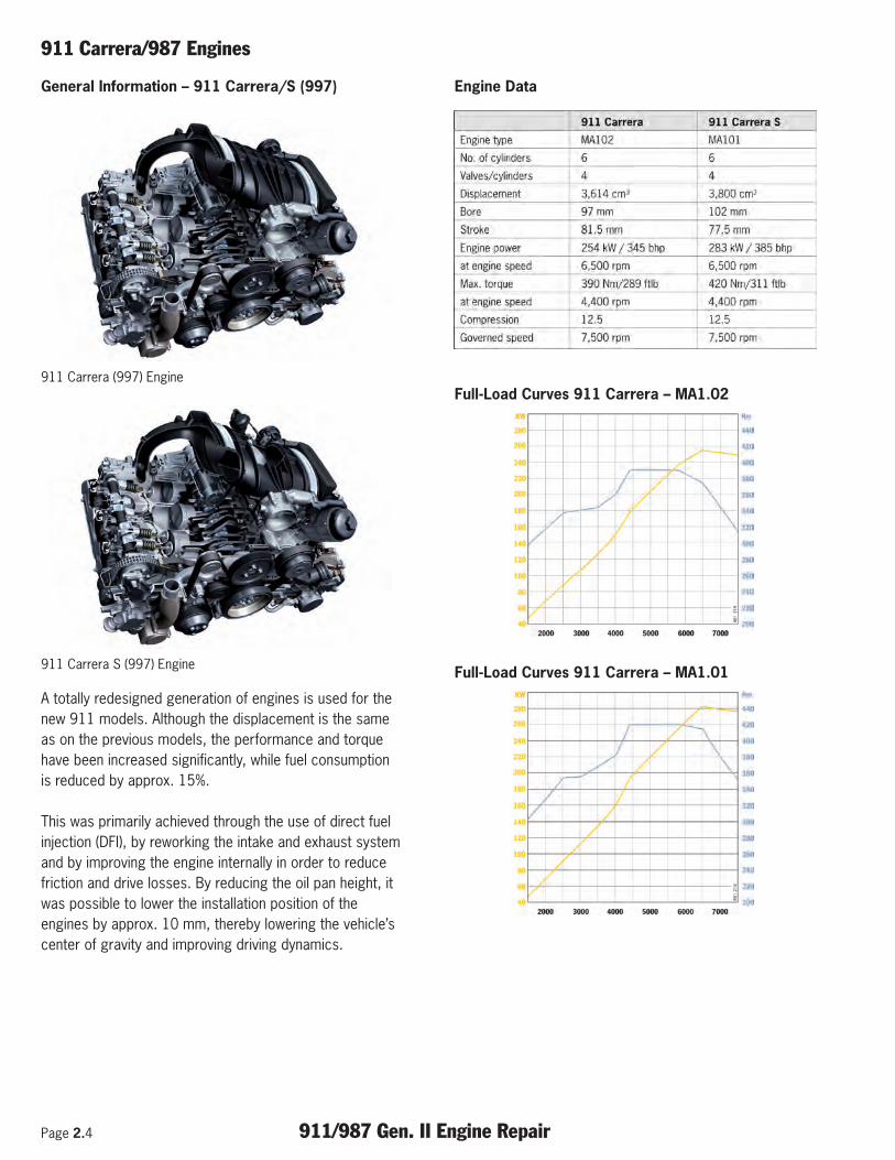
General Information – 911 Carrera/S (997)
911 Carrera (997) Engine
911 Carrera S (997) Engine
A totally redesigned generation of engines is used for thenew 911 models. Although the displacement is the sameas on the previous models, the performance and torquehave been increased significantly, while fuel consumptionis reduced by approx. 15%.
This was primarily achieved through the use of direct fuelinjection (DFI), by reworking the intake and exhaust systemand by improving the engine internally in order to reducefriction and drive losses. By reducing the oil pan height, itwas possible to lower the installation position of theengines by approx. 10 mm, thereby lowering the vehicle’scenter of gravity and improving driving dynamics.
Engine Data
Full-Load Curves 911 Carrera – MA1.02
Full-Load Curves 911 Carrera – MA1.01

911 Carrera/987 Engines
911/987 Gen. II Engine Repair Page 2.5
Crankcase
The engines feature a two-part, vertically split crankcasewith an integrated crankshaft thrust block. The advantageof this design is that smaller components can be used,while the separate bearing saddle with cast-in cast ironelements is no longer needed, thereby reducing the overallweight of the engine.
The actual crankcase on the new 911 engines is madecompletely of an aluminum-silicon alloy (ALUSIL).
This procedure offers the following advantages:
• With ALUSIL, the crankcase can be made from onecast, without cylinder sleeves and without having tocoat the cylinder bores afterwards.
• ALUSIL is an excellent heat conductor and thereforeallows high specific engine output values.
• ALUSIL has excellent friction properties. Since thepistons and piston rings slide on the exposed siliconcrystals, they have a low tendency to seize.
• ALUSIL does not present any recycling problemsbecause the crankcase does not include any foreignmaterials, e.g. cast-in cast iron cylinder sleeves.
The listed advantages of the alloy are certainly importantarguments in its favor. Indeed, the low-pressure chill-casting procedure, which has since proved to be the bestsolution by far for casting ALUSIL, is an important prereq-uisite for reliable, mass-produced crankcase cast parts.
Cylinders are now connected differently in the cylinder-head cover area. The individual cylinders, which originallystood freely in the water jacket (open deck design), arenow connected by a closed cylinder deck (closed deckdesign). The advantage of this design is high cylinderstability, particularly the cylinder shape (roundness and lowcylinder deformation) over a wide load and temperaturerange. This has the added advantage of reducing frictionand thus reducing fuel consumption. Even piston andpiston-ring sealing has been improved as a result of thehigher retention of roundness of the cylinders. The entry ofoil from the crankcase into the combustion chambers andthe entry of the fuel-air mixture from the combustionchambers into the crankcase is reduced. This bothimproves consumption and reduces performance-inhibitingoverpressure caused by blow-by in the crankcase.
Notes:

Page 2.6 911/987 Gen. II Engine Repair
911 Carrera/987 Engines
Crankshaft/Crankshaft Bearings
The drop-forged crankshaft runs in eight bearings and hastwelve counterweights. Main bearing 4 is designed as athrust bearing. Axial play is determined by two thrustplates, which are inserted at the left and right of thebearing.
The main bearings are designed as plain bearings with adiameter of 63 mm. Main bearings 1/3/5/7/8 are smoothbearings, while main bearings 2/4/6 are groovedbearings. These grooved bearings supply oil to the lubrica-tion points of the crankshaft bearings.
The drive mechanism for the two drive chains for thecamshafts and demand- controlled oil pump is located onthe pulley side.
Connecting Rods
1 Plain compression ring2 Stepped taper-faced ring3 Oil scraper ring4 Piston5 Hook circlip6 Connecting rod7 Connecting rod bearing shell8 Piston pin
The connecting rods (6) are forged and are split (cracked)at the big end following machining. Both parts are alignedwith one another via the fractured surface. Although amatching number is not needed for cracked connectingrods because of the fact that each fractured surface has adifferent shape, matching numbers are used here toensure process safety. During installation, it is importantto ensure that this data matrix code is facing the exhaustside. The connecting rods are 140 mm long. The piston-pin circlips are secured with twist locks and have an addi-tional hook for removal.
Pistons
The pistons are forged. Mixture formation and the directfuel injection (DFI) combustion process require a newpiston crown shape. The piston crown is a relatively largepart of the combustion chamber and has a major influenceon efficient combustion. Its shape also affects mixturepreparation and fresh fuel-air mixture stabilization in thespark plug area during injection processes in the compres-sion phase in particular.
1 Manufacturer’s logo2 Date of production3 Manufacturer’s drawing number4 Weight group5 Arrow marking for intake side (visible on new pistons)6 Data matrix code (faces the intake side)7 Porsche part number8 Dimensional group
Note!
> Original pistons from the Porsche Spare Parts Catalog(PET) are only available in the dimensional group X.
> Observe the different weight groups.

911 Carrera/987 Engines
911/987 Gen. II Engine Repair Page 2.7
Piston Cooling
The piston crown temperature in the engines is reduced byway of piston injection cooling. The spray nozzles areforced-fitted into the crankcase and cannot be replaced.To ensure the necessary engine oil pressure at low rpmand high engine oil temperatures, these spray nozzles onlyopen at a higher oil pressure.
Belt Drive
The belt drive in the engines has been improved comparedwith pre vious models through the following measures inparticular:
• Dual poly V-belt• Light-alloy torsional vibration damper• Maintenance-free hydraulic belt tensioner
The use of a 6-groove dual poly V-belt makes it easier todrive the auxiliary units. As a result, two deflection rollersused on the previous models are no longer needed,thereby reducing the weight and torsional mass. The useof plastic pulleys (on auxiliary units) and a redesigned
torsional vibration balancer with improved dynamic properties also reduces the weight and torsional mass.Markings and fixing bores have been applied to the pulleyand crankcase to facilitate various maintenance and repairwork.
Belt Tensioner
The new maintenance-free, hydraulic belt tensioner with itsspeed-proportional damping minimizes the belt vibrationson the bearings in the system.
Notes:

Page 2.8 911/987 Gen. II Engine Repair
911 Carrera/987 Engines
Cylinder Head
The cylinder heads in the new engines are designed as asingle piece without a separate housing for the hydraulicbucket tappets. It was possible to reduce the weight of thenew cylinder heads compared to the previous models (two-part cylinder heads with a separate bucket tappet guidehousing) by using an improved casting process.
1 Exhaust valve2 Valve-seat ring, exhaust3 Intake valve4 Valve-seat ring, intake5 Valve guide6 Valve spring plate7 Valve-stem seal8 Valve spring, intake (inner)9 Valve spring, intake (outer)10 Valve spring plate11 Valve guide12 Valve spring plate13 Valve-stem seal14 Valve spring, exhaust (inner)15 Valve spring, exhaust (outer)16 Valve spring plate
Also in the intake ports and valve-seat rings have been designed for optimized flow and production based onextensive simulations and form the basis for achievinghigh specific power and torque values. The intake andexhaust camshafts have also been re-adjusted forimproved gas exchange. This allows both high maximumtorque and power output values as well as a high torqueeven at low engine speeds.
Cylinder Head Gasket
To ensure the excellent sealing quality of the surface ofthe multi-layer steel seal, it is covered with high tempera-ture-resistant plastic. The advantage of this steel seal isthat the heat can be conducted very well away from thecylinder head.
Camshaft Bearing
1 Bearing cover, inlet2 Bearing cover, outlet3 Dowel sleeve4 Bottom bearing cover5 Top bearing cover
The camshafts are supported in the cylinder head bymeans of bearing saddles. To avoid confusion, the bearingsaddles are stamped with the matching numbers and theletters “E” for intake and “A” for exhaust.

911 Carrera/987 Engines
911/987 Gen. II Engine Repair Page 2.9
Cylinder Head Cover
The cylinder head cover is a separate part made of lightalloy. To ensure excellent sealing, a rubber seal is fittedbetween the cylinder head and cylinder head cover.
Camshafts – Boxster/Cayman (987)
The exhaust and intake camshafts are driven directly bythe crankshaft via one duplex roller-type chain each. Onthe 2.9-liter engine, the intake valve lift is 3.6 mm (small)and 10 mm (large). On the 3.4-liter engine, the small valvelift is the same as on the 2.9-liter engine, while the largevalve lift is 10.5 mm. The exhaust valve lift is 9.7 mm onthe 2.9-liter engine, and 10.35 mm on the 3.4-liter engine.
The timing for both engines is as follows:
2.9 l engine 3.4 l engineIntake opens, large stroke, 18° after top 19° after TDClate dead center (TDC)Intake closes, large stroke, 45° after bottom 62° after BDClate dead center (BDC)Intake opens, small stroke, 38.5° after TDC 44° after TDClate Intake closes, small stroke, 18.5° before BDC 14° before BDCExhaust opens 34.5° before BDC 40° before BDCExhaust closes 0.5° after TDC 3° after TDC
Camshafts – 911 Carrera (997)
The exhaust and intake camshafts are driven directly bythe crankshaft via one duplex roller-type chain each. Onthe 3.6-liter engine, the intake valve lift is 3.6 mm (small)and 10.5 mm (large). On the 3.8-liter engine, the smallvalve lift is the same as on the 3.6-liter engine, while thelarge valve lift is 11.0 mm. The exhaust valve lift is 10.35mm on the 3.6-liter engine, and 11.00 mm on the 3.8-literengine.
The timing for both engines is as follows:
3.6 l engine 3.8 l engineIntake opens, large stroke, 19° after top 11° after TDClate dead center (TDC)Intake closes, large stroke, 62° after bottom 59° after BDClate dead center (BDC)Intake opens, small stroke, 44° after TDC 39° after TDClate Intake closes, small stroke, 14° before BDC 19° before BDCExhaust opens 40° before BDC 50° before BDCExhaust closes 3° after TDC 4° after TDC
Notes:

Page 2.10 911/987 Gen. II Engine Repair
911 Carrera/987 Engines
Chain Drive
1 Camshaft drive, intake side, cylinder bank 1 - 3 2 Diamond washer3 Camshaft drive, exhaust side, cylinder bank 1 - 3 4 Timing chain, cylinder bank 1 - 35 Camshaft drive, intake side, cylinder bank 4 - 66 Diamond washer 7 Camshaft drive, exhaust side, cylinder bank 4 - 68 Timing chain, cylinder bank 4 - 6
Another special feature of the new generation of enginesis that these engines no longer have an intermediate shaft.This drive shaft, which was fitted between the crankshaftand the camshafts on previous models, was required inorder to reduce the transmission ratio and thus thedynamic forces of the timing chains. Through the use ofnew, high-performance timing chains, it was possible tosimplify the drive mechanism for the camshafts in spite ofhigher rpms, thereby reducing the weight of the enginesignificantly by removing the intermediate shaft. Togetherwith an additional crankshaft bearing location, this allowsgreater stability and a significantly higher engine speedpotential.
Timing Drive Mechanism
The two timing chains are controlled by guide andtensioning rails. Two hydraulic chain tensioners connectedto the engine oil circuit ensure the required tensioning ofboth chains.
Camshaft Control With Valve-lift Adjustment(VarioCam Plus)
The requirements imposed on engine design with regardto customer requests for higher performance combinedwith improved driving comfort, compliance with emissionregulations and reduced fuel consumption give rise toconflicting design criteria. The development of VarioCamPlus was therefore based on the idea of producing avariable engine, which can be optimized for maximumperformance and also for regular driving in city traffic oron secondary roads. A control system for the intakecamshaft to vary the opening and closing times in combi-nation with a valve lift system is necessary.

911 Carrera/987 Engines
911/987 Gen. II Engine Repair Page 2.11
Camshaft Actuator
The camshaft control principle is based on the principle ofa vane controller. The adjustment range is 40° crankangle. The control unit determines the current position ofthe camshaft in relation to the crankshaft (actual angle) onthe basis of the speed sensor signal and the Hall sendersignal. The position control in the control unit receives thedesired nominal angle via the programmed map values(speed, load, engine temperature). A regulator in theMotronic unit activates the 4-way proportional valveaccording to the desired adjustment when there is a difference between the nominal angle and actual angle.
Vacuum Pump
The engines use a mechanical vacuum pump instead of aconventional sucking jet pump to provide the vacuum forthe brake booster and various vacuum valves. This pumpis driven by the corresponding exhaust camshaft on theright cylinder head (cylinder bank 4 to 6).
Fuel High-pressure Pump
The fuel high-pressure pump is located on the cylinderhead of cylinder bank 1 to 3 and is driven by the outletcamshaft.
Notes:

Page 2.12 911/987 Gen. II Engine Repair
911 Carrera/987 Engines
Positive Crankcase Ventilation
During combustion, every engine blows some of thecombustion gases past the piston towards the crankcase -these gases are called blow-by gases. If these gases arenot drawn off, the pressure in the crankcase wouldincrease considerably. A vent connection is fitted in thecrankcase for this reason. For environmental protectionreasons, these gases are not released into the atmos-phere but are sent back to the engine for combustion viathe intake system.
Of course, these positive crankcase ventilation gasescontain a high proportion of engine oil and other combus-tion residues as well as a lot of fuel residues in somecases. If these gases get into the intake duct, they willcontaminate the intake air and can then impair runningsmoothness, exhaust emissions and reduce knock resistance. It is obvious for these reasons why effective oilseparation is important for the engine.
On the new flat engines this task is performed by the oilmist separator, which consists of a pre-separator and afine separator.
1 Oil filter cover2 Sealing ring3 Oil filter element4 Heat exchanger5 Oil mist separator6 Seal7 Pre-separator, top part8 Seal9 Pre-separator, bottom part10 Pre-separator
Oil Supply
The oil supply in the new generation of engines has beenessentially redesigned with the following objectives inmind:
• To ensure the supply of oil even during very high lateraland axial accelera tion
• To reduce friction and drive losses
The main differences between the new oil supply systemand that used on previous models are as follows:
• Additional oil extraction point in the cylinder head• Electronic demand-controlled oil pump• Additional watertight sheetmetal panel betweencrankcase and oil pan
Compared with the previous models, the new 987/997engines engines have not only one, but two extractionpoints in each cylinder head. In addition, the new enginesnow have a total of 5 oil pumps instead of 3. These arelocated in the oil pan and are driven by a shared shaft.They include 4 extraction pumps for the cylinder heads (2per cylinder head) and a new demand-controlled oilpressure pump.
Demand-controlled Oil Pump
In order to reduce drive losses from auxiliary units andimprove the efficiency of the engine, while at the sametime reducing fuel consumption, the new 911 Carreramodels are fitted with an electronic demand-controlled oilpump.
With this new oil pump, the delivery pressure and volumeis controlled for the entire engine map. In other words: therequired oil pressure and a defined oil volume is set foreach engine operating state (e.g. different engine speedand load). The oil pump is integrated neatly in the oil panarea and is driven directly by the crankshaft via a chain.

911 Carrera/987 Engines
911/987 Gen. II Engine Repair Page 2.13
Function
Depending on the input values for engine speed, engineload, engine oil tempera ture and the expected change inengine speed, a specific control valve (4) position isdefined using a map in the DME control unit. The controlvalve position regulates the oil pressure for the springpiston on the gear wheel, which can move in axial direction.The oil pressure on the control piston is not regulated onthe other side. The control valve is open fully in the non-energized state and as a result, the oil pressure is thesame on both sides, which means that the gear wheel willnot move. In other words: the pressure difference betweenthe spring piston and the control piston can be used tocontrol every position. When the gear wheel moves, theteeth are still only partially engaged and as a result, powerand friction as well as energy requirements are reduced.
1 Drive wheel2 Fixed gear wheel3 Axially displaceable gear wheel4 Control valveA De-energizedB Fully energized

Page 2.14 911/987 Gen. II Engine Repair
911 Carrera/987 Engines
Oil Circuit
911 Carrera/987 Engines
911/987 Gen. II Engine Repair Page 2.15
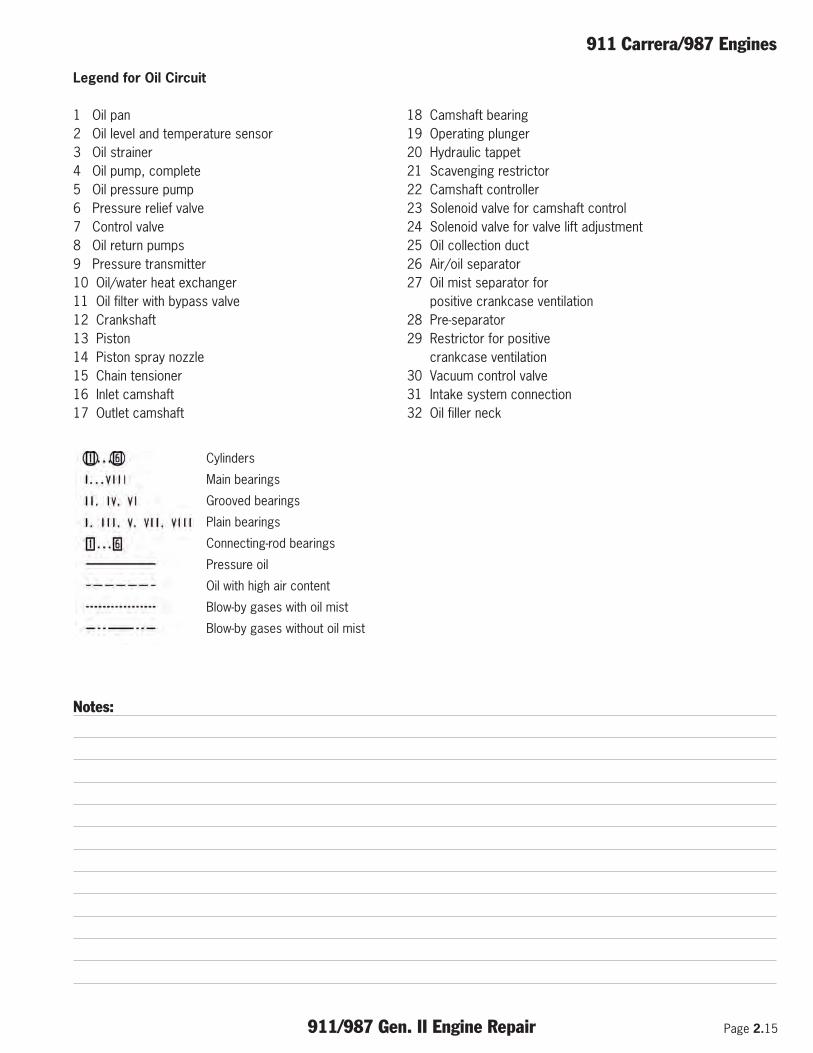
Legend for Oil Circuit
1 Oil pan 18 Camshaft bearing2 Oil level and temperature sensor 19 Operating plunger3 Oil strainer 20 Hydraulic tappet4 Oil pump, complete 21 Scavenging restrictor5 Oil pressure pump 22 Camshaft controller6 Pressure relief valve 23 Solenoid valve for camshaft control7 Control valve 24 Solenoid valve for valve lift adjustment8 Oil return pumps 25 Oil collection duct9 Pressure transmitter 26 Air/oil separator10 Oil/water heat exchanger 27 Oil mist separator for 11 Oil filter with bypass valve positive crankcase ventilation12 Crankshaft 28 Pre-separator13 Piston 29 Restrictor for positive14 Piston spray nozzle crankcase ventilation15 Chain tensioner 30 Vacuum control valve16 Inlet camshaft 31 Intake system connection17 Outlet camshaft 32 Oil filler neck
Cylinders
Main bearings
Grooved bearings
Plain bearings
Connecting-rod bearings
Pressure oil
Oil with high air content
Blow-by gases with oil mist
Blow-by gases without oil mist
Notes:

Page 2.16 911/987 Gen. II Engine Repair
911 Carrera/987 Engines
Cooling
The cooling concept is an enhancementbased on the effective cylinder headcrossflow cooling used on previous modelsand was developed to selectively cool thehot spots in the cylinder head andcrankcase. The design and position of thenew coolant pump as well as the revampedinternal engine cooling ducts in particular inthe cylinder head are new.
The new coolant pump is no longer locatedin the crankcase as an integral component,but instead it is attached to the outside ofthe crankcase on cylinder bank side 1-3 asa separate module driven by the belt. Theadvantage of this design is that it flexiblyadapts the size of the water pump andreduces the maintenance costs ifmaintenance is required. To adapt to theimproved engine performance and ensureadequate engine cooling, the maximumvolume flow of the new pump has beenincreased by approx. 20%.
Boxster/Cayman (987)
911 Carrera (997)
Notes:
911 Turbo Engine
911/987 Gen. II Engine Repair Page 3.1
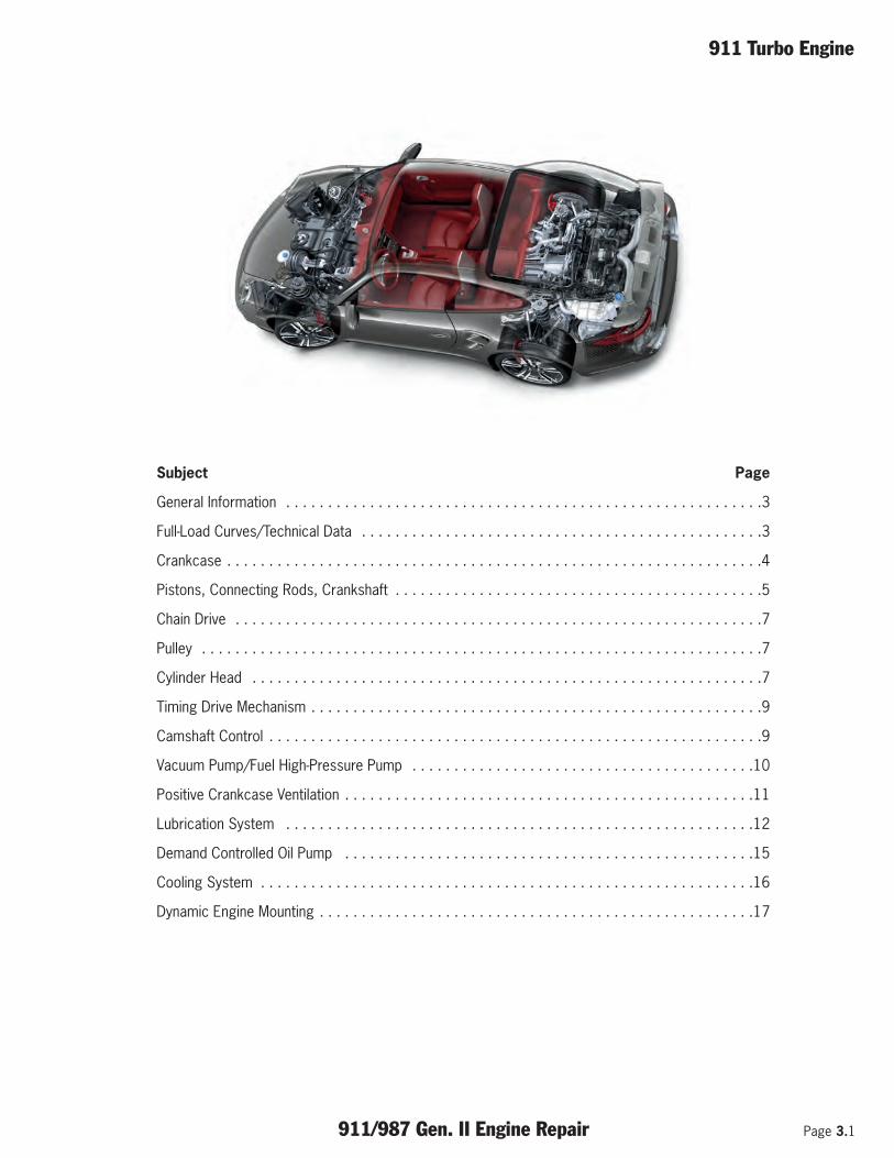
Subject Page
General Information . . . . . . . . . . . . . . . . . . . . . . . . . . . . . . . . . . . . . . . . . . . . . . . . . . . . . . . . .3
Full-Load Curves/Technical Data . . . . . . . . . . . . . . . . . . . . . . . . . . . . . . . . . . . . . . . . . . . . . . . .3
Crankcase . . . . . . . . . . . . . . . . . . . . . . . . . . . . . . . . . . . . . . . . . . . . . . . . . . . . . . . . . . . . . . . .4
Pistons, Connecting Rods, Crankshaft . . . . . . . . . . . . . . . . . . . . . . . . . . . . . . . . . . . . . . . . . . . .5
Chain Drive . . . . . . . . . . . . . . . . . . . . . . . . . . . . . . . . . . . . . . . . . . . . . . . . . . . . . . . . . . . . . . .7
Pulley . . . . . . . . . . . . . . . . . . . . . . . . . . . . . . . . . . . . . . . . . . . . . . . . . . . . . . . . . . . . . . . . . . .7
Cylinder Head . . . . . . . . . . . . . . . . . . . . . . . . . . . . . . . . . . . . . . . . . . . . . . . . . . . . . . . . . . . . .7
Timing Drive Mechanism . . . . . . . . . . . . . . . . . . . . . . . . . . . . . . . . . . . . . . . . . . . . . . . . . . . . . .9
Camshaft Control . . . . . . . . . . . . . . . . . . . . . . . . . . . . . . . . . . . . . . . . . . . . . . . . . . . . . . . . . . .9
Vacuum Pump/Fuel High-Pressure Pump . . . . . . . . . . . . . . . . . . . . . . . . . . . . . . . . . . . . . . . . .10
Positive Crankcase Ventilation . . . . . . . . . . . . . . . . . . . . . . . . . . . . . . . . . . . . . . . . . . . . . . . . .11
Lubrication System . . . . . . . . . . . . . . . . . . . . . . . . . . . . . . . . . . . . . . . . . . . . . . . . . . . . . . . .12
Demand Controlled Oil Pump . . . . . . . . . . . . . . . . . . . . . . . . . . . . . . . . . . . . . . . . . . . . . . . . .15
Cooling System . . . . . . . . . . . . . . . . . . . . . . . . . . . . . . . . . . . . . . . . . . . . . . . . . . . . . . . . . . .16
Dynamic Engine Mounting . . . . . . . . . . . . . . . . . . . . . . . . . . . . . . . . . . . . . . . . . . . . . . . . . . . .17

Page 3.2 911/987 Gen. II Engine Repair
911 Turbo Engine
Notes:

911 Turbo Engine
911/987 Gen. II Engine Repair Page 3.3
General Information
The model year 2010 911 Turbo received a completelynewly developed engine based on the naturally aspiratedengine of the 911 Carrera 2nd generation. The displace-ment has been increased from 3.6 l to 3.8 l comparedwith the previous Turbo model.
The engine still retains the following important basiccharacteristics:
• 6-cylinder horizontally opposed engine• Turbocharger with variable turbine geometry (VTG)• 4-valve technology with hydraulic valve clearance com-
pensation• Intake camshaft control and valve lift adjustment (Vario-
Cam Plus)
The development objectives for the new 911 Turboengine were:
• Increased power and torque over the entire engine rpmrange
• Reduced fuel consumption and CO2 emissions• Improved responsiveness• Extended usable engine rpm range• Reduced system weight to increase performance
These objectives were achieved with the followingnew features and enhancements:
• Completely new, weight-reduced basic engine• Increased displacement from 3.6 l to 3.8 l• Direct fuel injection• Weight-reduced valve and timing drive mechanism (to in-
crease the maximum engine speed from 6750 rpm to7000 rpm)
• Overboost function with higher maximum torques (incombination with the optional Sport Chrono Package Turbo)
• Cylinder heads with tumble intake ports • Expansion intake manifold• Integrated dry-sump lubrication• Electronic demand-controlled oil pump
Engine Data
Engine type . . . . . . . . . . . . . . . . . . . . . . . . . . . .MA170Number of cylinders . . . . . . . . . . . . . . . . . . . . . . . . . .6Displacement . . . . . . . . . . . . . . . . . . . . . . . . . . . .3800Bore . . . . . . . . . . . . . . . . . . . . . . . . . . . . . . . .102 mmCompression . . . . . . . . . . . . . . . . . . . . . . . . . . . . . .9.8Stroke . . . . . . . . . . . . . . . . . . . . . . . . . . . . . .77.5 mmValves per cylinder . . . . . . . . . . . . . . . . . . . . . . . . . . .4Engine power . . . . . . . . . . . . . . . . . . . .500 hp/368 kWAt engine speed . . . . . . . . . . . . . . . . . . . . . .6000 rpmMax. torque . . . . . . . . . . . . . . . . . . . . . . .650/700 NmAt engine speed . . . . . . . . . . . . . . . . .1950 - 5000 rpmFiring order . . . . . . . . . . . . . . . . . . . . . . . . .1-6-2-4-3-5Governed speed . . . . . . . . . . . . . . . . . . . . . .7000 rpmEngine weight . . . . . . . . . . . . . . . . . . . . .approx. 485 lb
Full-Load Curves

Page 3.4 911/987 Gen. II Engine Repair
911 Turbo Engine
The basic engine of the new 911 Turbo has beencompletely newly developed. Besides the conversion todirect fuel injection, the new design of the basic enginefocuses in particular on the integration of functions andreduction of components. The changes implemented havenot only reduced the overall weight of the engine byapprox. 26 lbs (12 kg), but also lowered its center ofgravity and therefore the overall center of gravity of thevehicle.
Compared with the previous model, the basicengine of the new 911 Turbo features the followingmain modifications:
• Increase in displacement to 3.8 l (cylinder diameterenlarged from 100 mm to 102 mm)
• Crankcase with integrated cylinder housing and cylinderliners
• Cylinder head with integrated camshaft housing andchain slot
• Omission of intermediate shaft• Oil supply with electronically demand-controlled oil pump• Integrated dry-sump lubrication with oil tank integrated
into the oil pan
Crankcase
Four complex components and four large sealing jointshave been dispensed with thanks to the one-piece designof the crankcase and cylinder housing (including cylinderliners) as well as the cylinder head and camshaft housing.The reduced number of screw connections alsocontributes to the reduction in engine weight. Componentintegration has made it possible to save a total of approx.45 main screw connections (50 %) compared with theprevious model and therefore approx. 2.9 lbs ( 1.3 kg) ofhardware alone.
The basic engine for the 911 Turbo was enhanced on thebasis of the current 911 Carrera generation of engineswith the same objective of reducing weight by integratingcomponents and functions. Component strength wasensured taking into account the much higher loads andadditional demands placed on the oil supply.
Compared with the current 911 Carrera models, thenew 911 Turbo features the following main modifi-cations:
• Lightweight crankcase made from Alusil with specialheat treatment and gas-nitrided crankshaft
• Cylinder head with modified air flow channels andimproved coolant flow
• Pistons and connecting rods with modified geometry forhigher loads
• Improved cooling through enlarged water pump
Notes:

911 Turbo Engine
911/987 Gen. II Engine Repair Page 3.5
The fully aluminum crankcase of the new 911 Turbo ismade from an aluminum-silicon alloy (Alusil) and is manu-factured in a unique casting process (chilled casting).Compared with the previous model with its own cylinderhousing and separate aluminum cylinder sleeves, the newcrankcase is much more compact and lighter.
The basic form of the crankcase is the same as thecurrent 911 Carrera generation. To ensure that the higherload requirements for the new 911 Turbo are met, thestrength of the crankcase was increased by reinforcingthe cylinder walls and using special heat treatment. Inaddition to the heat treatment with approx. 482° F.(250° C) used in the 911 Carrera engines, the 911 Turboengine receives advance heat treatment at approx. 932°F. (500° C). Structural changes occur during this phasewhich increase strength. After a cooling phase, internalstresses are reduced in a second heating phase. Thisstabilises the material properties, including the desiredbalance between strength and expansion.
The chill-casting process enables realisation of a closed-deck crankcase with integrated crankshaft bearings. Inthis design, the individual cylinders are connected by aclosed cylinder deck. The advantage of this design is highcylinder stability over a wide load and temperature range,which enables low friction for favourable fuel consump-tion.
The consistent roundness retention of the cylinders alsoimproves the sealing of the pistons and piston ringsbetween the crankcase and combustion chamber. Oilingress from the crankcase into the combustionchambers and transport of the fuel-air mixture from thecombustion chambers into the crankcase are therebyreduced. This improves oil consumption and also reducesperformance-inhibiting pump losses in the crankcase(blow-by).
The durability of the cylinder liners was ensured in theprevious model by a Nikasil® liner concept with a galvani-cally applied nickel layer. This system requires a complexcoating process and can be used only to a limited extentin complex component designs. Instead of individualcylinder sleeves, the new 911 Turbo has a complexcrankcase with integrated cylinders in a closed-deckconstruction. The crankcase is made using a specialcasting process (chilled casting) from an aluminum-siliconalloy (Alusil). This enables realization of durable cylinderliners using an Alusil liner concept.
Pistons
The mixture formation and combustion processes fordirect fuel injection (DFI) require a new piston crownshape. This was adapted in the new 911 Turbo toincrease the compression ratio from 9.0:1 to 9.8:1 and to therefore also improve the engine efficiency.
Like in the previous model, forged aluminum pistons areused to reliably achieve the high performance values ofthe new engine. Piston ring design details were optimizedto minimize frictional losses and the first ring was addi-tionally provided with a high-quality coating. As a contribu-tion to increasing the displacement from 3.6 l to 3.8 l, thepiston diameter of the new 911 Turbo was increased from100 mm to 102 mm and the piston stroke from 76.4 mmto 77.5 mm.
Groove 1 Plain compression ring
Groove 2 - Stepped taper-faced ring
Groove 3 Steel band oilscraper ring

Page 3.6 911/987 Gen. II Engine Repair
911 Turbo Engine
To reduce the lateral forces and ensure reliable transmis-sion of the enormous gas forces from the piston to thecrankshaft, the connecting rod was lengthened from 127mm to 140 mm compared with the previous model and itsoverall shape modified.
A computer-optimized design of pistons and connectingrod in combination with a short compression heightpermits the components to be designed with an optimumpower-to-weight ratio. The low mass forces bring about areduction in the crank drive loads and a further increase inthe smooth running of the new 911 engines.
The high-grade coating of the first piston ring is a DLCcoating. (DLC = Diamond-Like Carbon; a coating tech-nology used, for example, for high-performance cuttingtools for machining metal; it is an amorphous carbon layerwith outstanding anti-friction and wear properties).
Piston Cooling
The piston crown temperature in the 911 Turbo engines isreduced by means of piston injection cooling. The spraynozzles are pressed in the crankcase. To ensure thenecessary engine oil pressure at low rpm and high engineoil temperatures, these spray nozzles open at 26 psi (1.8 bar).
Crankshaft
Like the previous model, the new 911 Turbo features agas-nitrided crankshaft with a special surface hardness totransfer the high forces. The crankshaft is drop-forged,runs on eight bearings and has twelve balancing weights.The main bearing 4 is designed as a thrust bearing. Axialplay is determined by two thrust plates, which areinserted at the left and right of the bearing. The mainbearings are designed as plain bearings with a diameterof 63 mm. The drive mechanism for the two drive chainsfor the camshafts and demand-controlled oil pumpis located on the pulley side.
Notes:
911 Turbo Engine
911/987 Gen. II Engine Repair Page 3.7
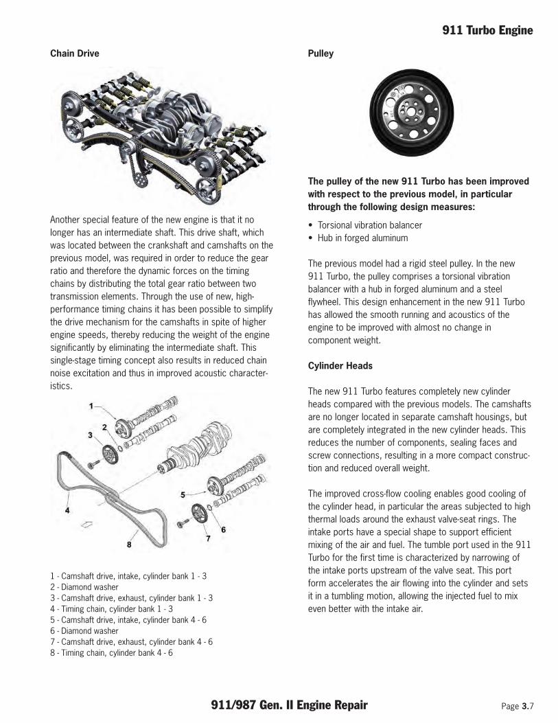
Chain Drive
Another special feature of the new engine is that it nolonger has an intermediate shaft. This drive shaft, whichwas located between the crankshaft and camshafts on theprevious model, was required in order to reduce the gearratio and therefore the dynamic forces on the timingchains by distributing the total gear ratio between twotransmission elements. Through the use of new, high-performance timing chains it has been possible to simplifythe drive mechanism for the camshafts in spite of higherengine speeds, thereby reducing the weight of the enginesignificantly by eliminating the intermediate shaft. Thissingle-stage timing concept also results in reduced chainnoise excitation and thus in improved acoustic character-istics.
1 - Camshaft drive, intake, cylinder bank 1 - 32 - Diamond washer3 - Camshaft drive, exhaust, cylinder bank 1 - 34 - Timing chain, cylinder bank 1 - 35 - Camshaft drive, intake, cylinder bank 4 - 66 - Diamond washer7 - Camshaft drive, exhaust, cylinder bank 4 - 68 - Timing chain, cylinder bank 4 - 6
Pulley
The pulley of the new 911 Turbo has been improvedwith respect to the previous model, in particularthrough the following design measures:
• Torsional vibration balancer• Hub in forged aluminum
The previous model had a rigid steel pulley. In the new911 Turbo, the pulley comprises a torsional vibrationbalancer with a hub in forged aluminum and a steelflywheel. This design enhancement in the new 911 Turbohas allowed the smooth running and acoustics of theengine to be improved with almost no change incomponent weight.
Cylinder Heads
The new 911 Turbo features completely new cylinderheads compared with the previous models. The camshaftsare no longer located in separate camshaft housings, butare completely integrated in the new cylinder heads. Thisreduces the number of components, sealing faces andscrew connections, resulting in a more compact construc-tion and reduced overall weight.
The improved cross-flow cooling enables good cooling ofthe cylinder head, in particular the areas subjected to highthermal loads around the exhaust valve-seat rings. Theintake ports have a special shape to support efficientmixing of the air and fuel. The tumble port used in the 911Turbo for the first time is characterized by narrowing ofthe intake ports upstream of the valve seat. This portform accelerates the air flowing into the cylinder and setsit in a tumbling motion, allowing the injected fuel to mixeven better with the intake air.

Page 3.8 911/987 Gen. II Engine Repair
911 Turbo Engine
1 - Exhaust valve2 - Valve-seat ring, exhaust3 - Intake valve4 - Valve-seat ring, intake5 - Valve guide6 - Valve-spring plate7 - Valve-stem seal8 - Valve spring, intake (inner)9 - Valve spring, exhaust (outer)10 - Valve-spring plate11 - Valve guide12 - Valve-spring plate13 - Valve-stem seal14 - Valve spring, exhaust (inner)15 - Valve spring, exhaust (outer)16 - Valve-spring plate
To ensure the excellent sealing quality of the surface ofthe multi-layer steel gasket, the gasket is covered withhigh temperature-resistant plastic. The advantage of thissteel gasket is that the heat can be conducted very wellaway from the cylinder head.
1 - Bearing cover, intake2 - Bearing cover, exhaust3 - Dowel sleeve4 - Lower bearing cover5 - Upper bearing cover
Cylinder Head Cover
The cylinder-head cover is a separate part made of light-alloy. To ensure excellent sealing, a rubber gasket is usedbetween the cylinder head and cylinder head cover.
Notes:

911 Turbo Engine
911/987 Gen. II Engine Repair Page 3.9
Camshafts
The camshafts are supported in the cylinder head bymeans of bearing saddles. To avoid confusion, thebearing saddles are stamped with the matching numbersand the letters “E” for intake and “A” for exhaust.
The timing is as follows:
Intake opens, large lift 17.6° after TDCIntake closes, large lift 55.3° after BDCIntake opens, small lift 38.5° after TDCIntake closes, small lift 18.7° before BDCExhaust opens 38.3° before TDCExhaust closes 6.3° before TDC
Timing Drive Mechanism
The two timing chains are controlled by guide andtensioning rails. Two hydraulic chain tensioners connectedto the engine oil circuit ensure the required tensioning ofboth chains.
Camshaft Control w/Valve-lift Adjustment (VarioCam Plus)
The requirements imposed on engine design with regardto customer requests for higher performance combinedwith improved driving comfort, compliance with variousemission regulations and reduced fuel consumption giverise to conflicting design criteria. The development ofVarioCam Plus was therefore based on the idea ofproducing a variable engine, which can be optimized formaximum performance and also for regular driving in citytraffic or on the highway. This requires a control systemfor the intake camshaft to vary the opening and closingtimes in combination with a valve lift system.
The camshaft control principle is based on the principle ofa vane controller. The adjustment range is 40° crankangle. The control unit determines the current position ofthe camshaft in relation to the crankshaft (actual angle) onthe basis of the speed sensor signal and the Hall sendersignal. The position control in the control unit receives thedesired set point angle via the programmed map values(engine speed, load, engine temperature). A regulator inthe Motronic unit activates the 4-way proportional valveaccording to the desired adjustment if there is a differ-ence between the set point angle and actual angle.
Page 3.10 911/987 Gen. II Engine Repair
911 Turbo Engine
Vacuum Pump
The 911 Turbo engines use a mechanical vacuum pumpinstead of a conventional sucking jet pump to provide thevacuum for the brake booster and various vacuum valves.This pump is driven by the corresponding exhaustcamshaft on the right cylinder head (cylinder bank 4 to 6).
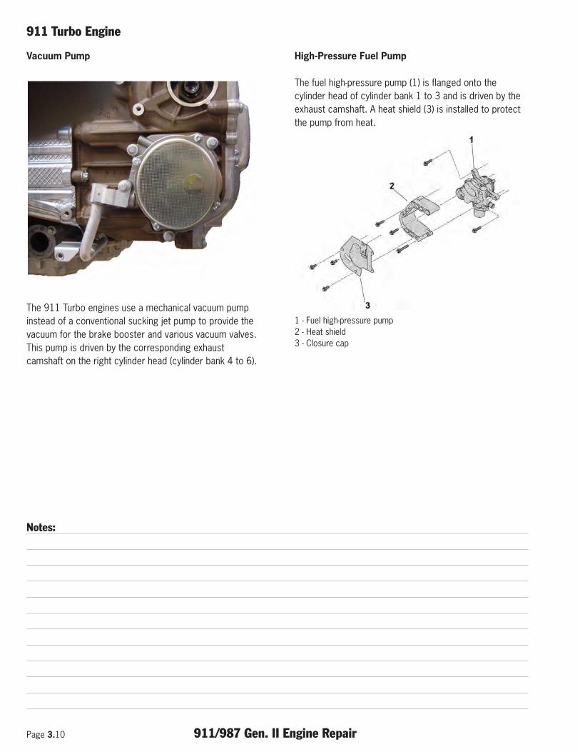
High-Pressure Fuel Pump
The fuel high-pressure pump (1) is flanged onto thecylinder head of cylinder bank 1 to 3 and is driven by theexhaust camshaft. A heat shield (3) is installed to protectthe pump from heat.
1 - Fuel high-pressure pump2 - Heat shield3 - Closure cap
Notes:

911 Turbo Engine
911/987 Gen. II Engine Repair Page 3.11
During combustion, every engine blows some of thecombustion gases past the pistons towards thecrankcase - these gases are called blow-by gases. If thesegases were not removed, the pressure in the crankcasewould increase considerably. A vent connection is installedin the crankcase for this reason. For environmentalprotection reasons, these gases are not released into theatmosphere but are returned to the engine for combustionvia the intake system. These crankcase ventilation gasesnaturally contain a high proportion of engine oil and othercombustion residues as well as high level of fuel residuesin some cases. If these gases enter the intake duct, theywill contaminate the intake air and can then impair runningsmoothness and exhaust emissions and also reduceknock resistance. It is obvious for these reasons whyeffective oil separation is important for the engine.
The crankcase ventilation has been completelyredesigned. Apart from the prevention of excesspressures, positive ventilation of the crankcase has beenimplemented. The aim of ventilation is to flush thecrankcase with fresh air. This is done by taking air fromthe pressure pipe upstream of the throttle valve andfeeding it through a separate restrictor and line straightinto the crankcase.
As boost pressure builds in the pressure pipe andconnecting line, the crankcase is positively ventilated andflushed with fresh air.
The advantage of positive crankcase ventilation is areduction in the penetration of fuel and water into the oil.Under certain operating conditions (in particular during acold start and when at full throttle), molecules of fuel andwater are deposited on the cylinder wall. These can maketheir way past the piston rings into the crankcase. Anymixing of these elements with the oil impairs the lubri-cating properties of the oil.
Positive Crankcase Ventilation
1 - Engine2 - Crankcase breather3 - Oil separator module4 - Intake air line5 - Turbocharger6 - Restrictor 2.70 mm (4x)7 - Restrictor 1.68 mm8 - Check valve9 - Throttle valve10 - Oil pan11 - Oil collection containerA - Partial load ventilationB - Full load ventilation

Page 3.12 911/987 Gen. II Engine Repair
911 Turbo Engine
Lubrication System
The new 911 Turbo features a completely redesigned oilsupply.
This is characterised by the following items:
• Integrated dry-sump lubrication• A total of 7 oil pumps• Electronically demand-controlled oil pressure pump
The main difference from the previous models is in thedry-sump lubrication. In the previous models, a separateengine oil tank ensured a sufficient oil supply, even in thecase of high lateral and longitudinal acceleration. In thenew 911 Turbo, this task is performed by dry-sump lubri-cation integrated in the oil pan. This design also ensures asufficient oil supply on race circuits, both when standardtires and sports tires (Ultra High Performance – UHP) areused.
Compared with the dry-sump lubrication withseparate engine oil tank used in the previousmodels, the integrated dry-sump lubrication in thenew 911 Turbo has the following advantages:
• Integrated dry-sump lubrication• Reliable oil supply, even on race tracks when using stan-
dard and sports tires (UHP)• Low weight• Lower engine and vehicle centre of gravity• Reduced drive power of the oil pumps• Lower system weight and therefore lower vehicle weight• Lower engine center of gravity and therefore lower vehi-
cle center of gravity
Instead of the 9 oil pumps used in the previous models,the new 911 Turbo has a total of 7 oil pumps for a reliableoil supply. All extraction points in the cylinders andturbochargers have been retained. By integrating the dry-sump lubrication into the oil pan and omitting the separateengine oil tank, it has been possible to also omit twoextraction pumps from the crankcase of the new 911 Turbo. These were needed in the previous models topump the oil from the crankcase to the separate engineoil tank. Omitting these oil pumps reduces the weight andeliminates the requirement for drive power for thesepumps. This in turn reduces fuel consumption and exhaustemissions.
The new 911 Turbo therefore has a total of 6 extractionpumps (previous model: 8) and one oil pressure pump asbefore. They are divided into 4 oil extraction pumps forthe cylinder heads (2 per cylinder head), 2 oil extractionpumps for the turbocharger and one oil pressure pump.
Notes:

911 Turbo Engine
911/987 Gen. II Engine Repair Page 3.13
The new oil pressure pump is an electronic demand-controlled oil pump designed to reduce the drive powerand churning loss.
Another modification concerns the location of the oilextraction pumps for the cylinder heads. In the previousmodels, these were located directly on the cylinder heads.In the new 911 Turbo, the pumps are integrated in theextraction pump module in the oil pan. This helps tofurther lower the engine’s center of gravity.
The compact oil supply of the integrated dry-sump lubrica-tion has also enabled a reduction in the oil filling quantityof the new 911 Turbo from approx. 11.0 l to approx. 10.4l (first filling). This measure helps to reduce weightcompared with the previous model for a total weightsaving of approx. 8.8 lbs (4 kg) in comparison to the oilsupply with separate engine oil tank, primarily by omittingthe separate engine oil tank and the 2 oil extractionpumps.
Another advantage is the engine’s much lower center ofgravity. In the previous model, the separate engine oiltank was an upright container mounted in front of theengine on the right in the direction of travel. Its center ofgravity was significantly above the crankshaft. In the new911 Turbo, the container for the oil of the integrated dry-sump lubrication is in the oil pan beneath the crankcaseand therefore well below the crankshaft. Relocating the oiltank for the dry-sump lubrication has lowered its center ofgravity by approx. 30 cm. This enables a lower enginecenter of gravity and therefore a lower vehicle center ofgravity, thereby enhancing driving dynamics.
The compact design of the oil pan has allowed the groundclearance in the area of the engine to be adoptedunchanged from the previous model, despite integrationof the dry-sump lubrication function. Compared with aconventional oil supply with pressure-fed lubrication and asimple oil pan, the oil pan in the new 911 Turbo is acomplex component. It serves as the oil tank of the inte-grated dry-sump lubrication and has a partition box and anadditional separator plate (watertight sheet metal panel)between the crankcase and the oil pan. This largelyseparates the two spaces and reduces both the churningloss in the crankcase and oil foaming in the oil pan,supported by two horizontally arranged air-oil separators(swirl pots).
Main changes compared with the 911 Carreramodels:
The principle of the integrated dry-sump lubrication in thenew 911 Turbo is basically adopted from that of thecurrent 911 Carrera models.
The following features have been enhanced for thenew 911 Turbo compared with the current 911Carrera models:
• 2 additional extraction pumps for the turbocharger• Larger oil/water heat exchanger• Control adaptation to the demand-controlled oil pump• Positive crankcase ventilation including adaptation to
the additional bearing ventilation of the turbochargers
Compared with the 911 Carrera models, the modular oilpump module in the oil pan has been extended by twostages for extraction of the turbocharger oil. In order tocope with the higher engine power and to avoid critical oiltemperatures, the power of the oil-water heat exchangerin the new 911 Turbo has been increased from 25 kW(911 Carrera) to 40 kW. The control of the demand-controlled oil pump has also been modified. This nowfeatures map-specific adjustment of the oil pressure to thehigher bearing and piston loads of the new 911 Turbo.Like its predecessor and the current 911 Carrera models,the new 911 Turbo also features piston spray cooling.

Page 3.14 911/987 Gen. II Engine Repair
911 Turbo Engine
Oil Circuit
Cylinders
Main bearings
Grooved bearings
Smooth bearings
Connecting-rod bearingsPressure oil
Oil with high air share
Blow-by gases with oil mist
Blow-by gases without oil mist
Air after air cleaner
Engine-transmission flange
Direction of travel
1 - Oil pan 21 - Scavenging restrictor2 - Oil-level and oil-temperature sensor 22 - Camshaft controller3 - Oil strainer 23 - Solenoid valve4 - Oil pump 24 - Solenoid valve, valve lift adjustment5 - Oil pressure pump 25 - Oil collection duct, cylinder head6 - Pressure relief valve 26 - Air/oil separator7 - 3/2 directional-control valve, oil pump control 27 - Oil mist separator for positive crankcase ventilation8 - Oil return pumps 28 - Pre- and fine separator9 - Oil pressure sensor 29 - Restrictor, positive crankcase ventilation10 - Oil-water heat exchanger 30 - Vacuum limiting valve11 - Oil filter with bypass valve 31 - Intake system connection12 - Crankshaft 32 - Oil filler neck13 - Piston 33 - Intake air line 1-3, partial load ventilation14 - Piston spray nozzle 34 - Intake air line 4-6, full load ventilation15 - Chain tensioner 35 - Vent line, crankcase16 - Camshaft, intake 36 - Check valve17 - Camshaft, exhaust 37 - Turbocharger18 - Camshaft bearing 38 - Bearing, turbocharger19 - Operating plungers 39 - Oil collection container, turbocharger20 - Hydraulic tappets 40 - Oil return pumps

911 Turbo Engine
911/987 Gen. II Engine Repair Page 3.15
Demand-Controlled Oil Pump
In order to reduce the drive losses of auxiliary units aswell as churning loss, the new 911 Turbo is fitted with anelectronic demand-controlled oil pump, analogously to thecurrent 911 Carrera models. This increases the engine'sefficiency, consequently reducing fuel consumption.
With this oil pump, the delivery pressure and volume arecontrolled for the entire engine map. In other words, therequired oil pressure is set for all engine speeds andengine loads (accelerator pedal position). Accordingly, theoil pressure shown in the instrument cluster varies basedon the engine speed and load. The oil pressure settingresults in a defined oil volume flow based on the definedleaks (e.g. bearing clearance of connecting rod and crank-shaft bearings). The oil pump is integrated compactly inthe oil pan area and is driven directly by the crankshaft viaa chain.
Demand-based control of the oil pump is provided by theengine management. The input variables are enginespeed, oil pressure, oil temperature and engine torque.On the basis of this information, axial movement of a gearwheel controls the engaged gear wheel width andchanges the geometric displacement volume. This in turnvaries the oil pressure. The demand-based control of theoil pump for the new 911 Turbo has been modified on thebasis of the 911 Carrera models and the control mapadapted to the higher bearing loads.
The demand-controlled pump also ensures that only thequantity of oil necessary for the respective load range ofthe engine is provided. This minimizes the energyconsumption of the oil pump and ensures demand-basedlubrication.
Notes:

Page 3.16 911/987 Gen. II Engine Repair
911 Turbo Engine
Like in the previous model, the new 911 Turbo alsofeatures water cooling of the cylinders and cylinder headsbased on the cross-flow principle with the water flowingfrom the hot to the cold side. This principle achieves ahomogeneous temperature distribution with even loads onthe components.
Despite the high cooling requirement, the engine of thenew 911 Turbo makes do with just one oil-water heatexchanger, although this is larger than the one used in the911 Carrera. The heat from the coolant is dissipated tothe environment by means of two side radiator modulesand one center radiator module in the front apron.
The water pump has been largely adopted from thecurrent 911 Carrera engines and is attached as aseparate module to the outside of the crankcase oncylinder bank side 1-3. To adapt to the improved engineperformance and ensure adequate engine cooling, thenew 911 Turbo features a water pump with increasedvolume flow. This is achieved by enlarging the water pumpimpeller.
As in the previous model, the bearing housings of theturbochargers in the new 911 Turbo are also cooled withwater. This is done by a separate electrically operatedwater pump. The pump increases water throughput at lowengine speeds to meet the cooling requirement. It alsopermits efficient cooling of the highly loaded turbo-chargers even when the engine is stopped after thevehicle has been driven with high power demands.
Sufficient supply of coolant to the turbochargers ispossible only to a restricted extent at low engine speedsand therefore at low water pump speeds of the conven-tional water pump as well as with a stopped engine. Thisis particularly the case after heavy engine loading. As aresult, coking of the lubricating oil in the bearing case andon the turbine shafts is only prevented to a limited extent.Here, the electrically operated additional pump supportscoolant throughput and also ensures sufficient cooling ofthe turbocharger under these operating conditions.
Cooling System
1 - Turbocharger 4 - 62 - Turbocharger 1 - 33 - Oil-water heat exchanger4 - Run-on pump5 - Coolant shutoff valve6 - PDK heat exchanger7 - Heat exchanger8 - Radiator, right9 - Radiator, left10 - Centre radiatorA - Thermostat slide openB - Thermostat slide closed
911 Turbo Engine
911/987 Gen. II Engine Repair Page 3.17
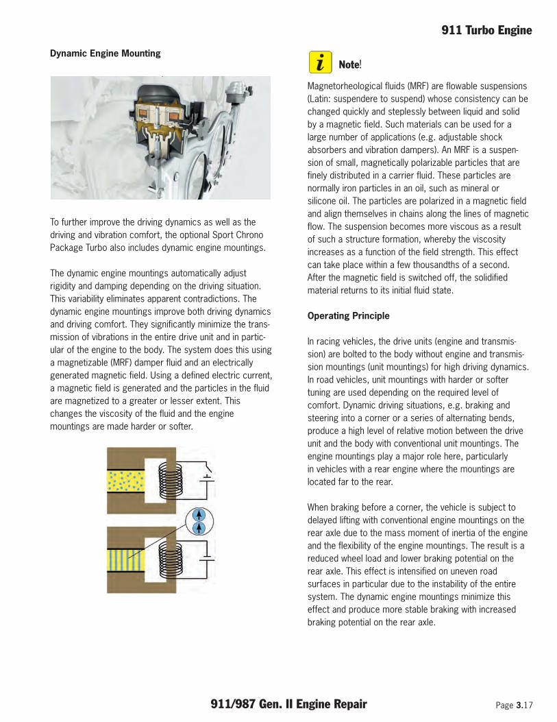
Dynamic Engine Mounting
To further improve the driving dynamics as well as thedriving and vibration comfort, the optional Sport ChronoPackage Turbo also includes dynamic engine mountings.
The dynamic engine mountings automatically adjustrigidity and damping depending on the driving situation.This variability eliminates apparent contradictions. Thedynamic engine mountings improve both driving dynamicsand driving comfort. They significantly minimize the trans-mission of vibrations in the entire drive unit and in partic-ular of the engine to the body. The system does this usinga magnetizable (MRF) damper fluid and an electricallygenerated magnetic field. Using a defined electric current,a magnetic field is generated and the particles in the fluidare magnetized to a greater or lesser extent. Thischanges the viscosity of the fluid and the enginemountings are made harder or softer.
Note!
Magnetorheological fluids (MRF) are flowable suspensions(Latin: suspendere to suspend) whose consistency can bechanged quickly and steplessly between liquid and solidby a magnetic field. Such materials can be used for alarge number of applications (e.g. adjustable shockabsorbers and vibration dampers). An MRF is a suspen-sion of small, magnetically polarizable particles that arefinely distributed in a carrier fluid. These particles arenormally iron particles in an oil, such as mineral orsilicone oil. The particles are polarized in a magnetic fieldand align themselves in chains along the lines of magneticflow. The suspension becomes more viscous as a resultof such a structure formation, whereby the viscosityincreases as a function of the field strength. This effectcan take place within a few thousandths of a second.After the magnetic field is switched off, the solidifiedmaterial returns to its initial fluid state.
Operating Principle
In racing vehicles, the drive units (engine and transmis-sion) are bolted to the body without engine and transmis-sion mountings (unit mountings) for high driving dynamics.In road vehicles, unit mountings with harder or softertuning are used depending on the required level ofcomfort. Dynamic driving situations, e.g. braking andsteering into a corner or a series of alternating bends,produce a high level of relative motion between the driveunit and the body with conventional unit mountings. Theengine mountings play a major role here, particularlyin vehicles with a rear engine where the mountings arelocated far to the rear.
When braking before a corner, the vehicle is subject todelayed lifting with conventional engine mountings on therear axle due to the mass moment of inertia of the engineand the flexibility of the engine mountings. The result is areduced wheel load and lower braking potential on therear axle. This effect is intensified on uneven roadsurfaces in particular due to the instability of the entiresystem. The dynamic engine mountings minimize thiseffect and produce more stable braking with increasedbraking potential on the rear axle.

Page 3.18 911/987 Gen. II Engine Repair
911 Turbo Engine
When steering into a corner, the vehicle follows thesteering movement directly. However, the engine tries tocontinue following a straight line in accordance with theprinciple of mass moment of inertia. The engine will onlyfollow the steering direction once the elasticity in theengine mountings has been overcome. In the case ofvehicles with a rear engine, the result is a delayedmomentum on the rear axle, which in turn produces anoversteer tendency when driving very dynamically. In thisdriving situation, the dynamic engine mountings are auto-matically set to hard. There is no delayed momentum andthe vehicle can move more precisely and without disrup-tive side effects in extreme driving situations, just like aracing car.
To reduce the effects of the mass moment of inertia ofthe engine, damping of the dynamic engine mountings isalso increased when driving through a series of alternatingbends and in the event of load changes. This reduces“pushing” from the rear and allows more stable andprecise handling.
The dynamic engine mountings also offer significantadvantages during acceleration from a standing start andat full throttle. Vertical engine vibrations are largelyreduced. The result is more uniform and higher drivepower at the rear axle with higher traction and betteracceleration. At low speeds and for comfort-orientateddriving, the dynamic engine mountings are made softeraccording to the condition of the road surface. Thisreduces the amount of natural vibrations from the engineto the body and therefore to the passenger compartment,particularly when driving on poor road surfaces. The resultis enhanced driving comfort with reduced vibration.
Function of Unit Mountings
The dynamic engine mountings contain an electric coiland two chambers filled with magnetorheological fluid.The upper chamber is coupled to the body, while thelower chamber is connected to the drive unit. Thechambers are connected to each other by means of anannular gap. The electric coil is located directly nextto this annular gap. Relative motion between the engineand the body presses the fluid through the annular gap.An electromagnetic field is generated in this annular gapby a defined electric current through the coil. Theviscosity of the magnetorheological fluid then changesand the engine mountings are made softer or harder.
When there is no current flowing through the coil, the fluidhas a relatively low viscosity and the flow resistance islow. The mountings have low rigidity and damping and arethus soft. When a defined current is applied to the coil,the iron particles in powder form in the fluid are magne-tized and join together to create chains. The fluidbecomes viscous and the flow resistance high. Themountings are then characterized by high rigidity anddamping and are therefore hard.
The system is controlled by a separate control unit with ahighly dynamic control loop and response times of just afew milliseconds when switching between soft and hardengine mountings. A large amount of information isprocessed, including the steering angle, lateral, longitu-dinal and vertical acceleration as well as the fluid pressurein the respective engine mounting. To ensure excellentdriving dynamics and functionality, vehicles with dynamicunit mountings feature separate and independent controlof the right and left engine mountings. The controlstrategy of the dynamic engine mountings is also influ-enced by the PSM vehicle stability system pre-setting.
System Components:
• 2 magnetorheological enginemountings with integrated sensors andcontrol
• 1 control unit with correspondingpower electronics
Engine mounting consists of:
Connection dimensions (interface between body andengine carrier)
The control unit includes:
• Controller functionalities (situation detection, safetylogic)
• Sensor system (body acceleration signal from the PASMcontrol unit)
• Actuator (one coil per engine mounting)• CAN Drive• Power electronics

911 Turbo Engine
911/987 Gen. II Engine Repair Page 3.19
“Dynamic engine mounting” allows the stiffness anddamping to be varied continuously on both enginemountings (left and right) in accordance with the detecteddriving situation. This reduces or minimizes the unitmovements and modes caused by road and drivetrainexcitations. These system adaptations lead to improve-ments in the driving dynamics (traction, handling) anddriving comfort (initial spring response, jerking, jitter).
A - Engine mounting installation positionB - Control unit installation position for CabrioletC - Control unit installation position for Coupe
The control algorithms for driving situationdetection and control of the unit mountings areprocessed in the control unit. The control unitfunctions include the following:
• Reading, filtering and quantifying the input signals• Supplying the algorithm for driving situation detection• Supplying the algorithm for the unit mountings• Executing the algorithms• Executing the diagnostic functions• Fault detection and fault management• Actuation of the mountings• Output of the fault status to the instrument cluster• Communication in the CAN network
Driving Situation Detection
The prevailing driving situation is detected by analgorithm in order to optimally adapt mountingcontrol to the respective situation. The followingsituations can be detected:
• Level road surface (Normal)• Level road surface (Sport)• Poor undulating road surface• Rapid increase in engine torque (pedal potentiometer)• Rapid reduction in engine torque (pedal potentiometer)• Racetrack driving• Full braking• Rapid acceleration (racing start)
Note!
Depending on the function setting – PSM ON / SportChrono (SC) OFF / SC+TC (Traction Control) OFF – thepre-set damping of the engine mountings is decreasedor increased as required for sporty driving. In thesportiest setting SC+TC OFF, for example, a controlstrategy suitable for race circuits with very high dampingof the engine mountings is selected.
The control parameters of the algorithm are adapted onthe basis of the detected driving situation. This ensuresthat the required stiffness and damping can be adjustedcontinuously at all times.
Note!
Explanation of algorithms:Algorithms are exactly defined rules or procedures forsolving a task in a finite number of steps.

Page 3.20 911/987 Gen. II Engine Repair
911 Turbo Engine
Notes:

Additional Notes
911/987 Gen. II Engine Repair Page 4.1

Page 4.2 911/987 Gen. II Engine Repair
Additional Notes

Additional Notes
911/987 Gen. II Engine Repair Page 4.3

Page 4.4 911/987 Gen. II Engine Repair
Additional Notes

Additional Notes
911/987 Gen. II Engine Repair Page 4.5

Page 4.6 911/987 Gen. II Engine Repair
Additional Notes
Notes:

Conversion Charts
911/987 Gen. II Engine Repair Page 5.1
Metric Conversion Formulas
INCH . . . . . . . . . . . . . X 25.4 = MMMM . . . . . . . . . . . . . . X .0394 = INCHMILE . . . . . . . . . . . . . X 1.609 = KILOMETER (KM)KM (KILOMETER) . . . . . . . . X .621 = MILEOUNCE . . . . . . . . . . . X 28.35 = GRAMGRAM . . . . . . . . . . . . X .0352 = OUNCEPOUND (lb) . . . . . . . . . X .454 = KILOGRAM (kg)kg (KILOGRAM) . . . . . . . . . X 2.2046 = lb (POUND)CUBIC INCH . . . . . . . . X 16.387 = CUBIC CENTIMETER (cc)cc (CUBIC CENTIMETER) . . . . . X .061 = CUBIC INCHLITERS. . . . . . . . . . . . X .0353 = CUBIC FEET (cu.ft.)CUBIC FEET (cu.ft.) . . . . . . . . X 28.317 = LITERSCUBIC METERS . . . . . X 35.315 = CUBIC FEET (cu.ft.)FOOTPOUND(ft lb) . . . . . X 1.3558 = NEWTON METER (Nm)Nm (NEWTON METER) . . . . . . X .7376 = ft lb (FOOT POUND) HORSEPOWER (SAE) . . . X .746 = KILOWATT (Kw)HORSEPOWER (DIN) . . . X .9861 = HORSEPOWER (SAE)Kw (KILOWATT) . . . . . . . . . X 1.34 = HORSEPOWER (SAE)HORSEPOWER (SAE) . . . X 1.014 = HORSEPOWER (DIN)MPG (MILES PER GALLON) . . . X .4251 = Km/l (KILOMETER PER LITER)BAR . . . . . . . . . . . . . . X 14.5 = POUND/SQ. INCH (PSI)PSI (POUND SQUARE INCH). . . . X .0689 = BARGALLON. . . . . . . . . . . X 3.7854 = LITERLITER. . . . . . . . . . . . . X .2642 = GALLONFAHRENHEIT . . . . . . . - 32÷1.8 = CELSIUSCELSIUS . . . . . . . . . . X 1.8+32 = FAHRENHEIT
TemperatureConversion

Page 5.2 911/987 Gen. II Engine Repair
Conversion Charts
Notes:


Part Number - PNA P10 WDF 02