AFRL-IF-WP-TR -2001-1530 - apps.dtic.mil · David Corman Pat Goertzen Tom Herm John Shackleton ......
118
AFRL-IF-WP-TR-2001-1530 INCREMENTAL UPGRADE OF LEGACY SYSTEMS (IULS) Don Winter David Corman Pat Goertzen Tom Herm John Shackleton The Boeing Company P.O. Box 516 St. Louis, MO 63166-0516 APRIL 2001 Final Report for 30 September 1996 – 28 February 2001 Approved for public release; distribution is unlimited. INFORMATION DIRECTORATE AIR FORCE RESEARCH LABORATORY AIR FORCE MATERIEL COMMAND WRIGHT-PATTERSON AIR FORCE BASE, OH 45433-7334
Transcript of AFRL-IF-WP-TR -2001-1530 - apps.dtic.mil · David Corman Pat Goertzen Tom Herm John Shackleton ......

AFRL-IF-WP-TR -2001-1530 INCREMENTAL UPGRADE OF LEGACY SYSTEMS (IULS) Don Winter David Corman Pat Goertzen Tom Herm John Shackleton The Boeing Company P.O. Box 516 St. Louis, MO 63166-0516 APRIL 2001
Final Report for 30 September 1996 – 28 February 2001
Approved for public release; distribution is unlimited.
INFORMATION DIRECTORATE AIR FORCE RESEARCH LABORATORY AIR FORCE MATERIEL COMMAND WRIGHT-PATTERSON AIR FORCE BASE, OH 45433-7334


i
REPORT DOCUMENTATION PAGE Form Approved OMB No. 0704-0188
The public reporting burden for this collection of information is estimated to average 1 hour per response, including the time for reviewing instructions, searching existing data sources, searching existing data sources, gathering and maintaining the data needed, and completing and reviewing the collection of information. Send comments regarding this burden estimate or any other aspect of this collection of information, including suggestions for reducing this burden, to Department of Defense, Washington Headquarters Services, Directorate for Information Operations and Reports (0704-0188), 1215 Jefferson Davis Highway, Suite 1204, Arlington, VA 22202-4302. Respondents should be aware that notwithstanding any other provision of law, no person shall be subject to any penalty for failing to comply with a collection of information if it does not display a currently valid OMB control number. PLEASE DO NOT RETURN YOUR FORM TO THE ABOVE ADDRESS.
1. REPORT DATE (DD-MM-YY) 2. REPORT TYPE 3. DATES COVERED (From - To)
April 2001 Final 09/30/1996 – 02/28/2001 5a. CONTRACT NUMBER
F33615-96-C-1969 5b. GRANT NUMBER
4. TITLE AND SUBTITLE
INCREMENTAL UPGRADE OF LEGACY SYSTEMS (IULS)
5c. PROGRAM ELEMENT NUMBER 63253F
5d. PROJECT NUMBER
3833 5e. TASK NUMBER
04
6. AUTHOR(S)
Don Winter David Corman Pat Goertzen Tom Herm John Shackleton
5f. WORK UNIT NUMBER
02 7. PERFORMING ORGANIZATION NAME(S) AND ADDRESS(ES) 8. PERFORMING ORGANIZATION
REPORT NUMBER
The Boeing Company P.O. Box 516 St. Louis, MO 63166-0516
BOEING-STL-00P0074
9. SPONSORING/MONITORING AGENCY NAME(S) AND ADDRESS(ES) 10. SPONSORING/MONITORING AGENCY ACRONYM(S)
AFRL/IFTA
11. SPONSORING/MONITORING AGENCY REPORT NUMBER(S)
Information Directorate Air Force Research Laboratory Air Force Materiel Command Wright-Patterson AFB, OH 45433-7334 AFRL-IF-WP-TR-2001-1530
12. DISTRIBUTION/AVAILABILITY STATEMENT
Approved for public release; distribution is unlimited. 13. SUPPLEMENTARY NOTES
Report contains color. 14. ABSTRACT
This program developed, demonstrated, and is transitioning technology that will enable cost-effective, incremental improvements to fielded embedded systems. The IULS wrapper technology was flight tested on an F-15 with no anomalies. IULS software tools automatically generated 99 percent of the wrapper software. This technology provides a low risk, affordable approach to system upgrades in response to computer-diminished manufacturing resources. It supports faultless and simultaneous execution of new and legacy software and can be used to accelerate the insertion of new technology into Air Force weapon systems and information systems. The IULS program consisted of two tasks. Task 1 was to define incremental software upgrade processes and supporting avionics architectures, identify and evaluate candidate solutions, and identify the preferred approaches for demonstration. Task 2 was to develop reusable legacy wrappers, adapt an off-the-shelf CASE toolset to IULS specific needs, mature the incremental software upgrade process by using the CASE toolset to configure a wrapper for the F-15 OFP, demonstrate the wrapped OFP on a COTS multiprocessor, and transition this technology to customer-selected weapon systems avionics upgrade programs. IULS emulation technology was successfully demonstrated on C-17 hardware in the C-17 integration laboratory.
15. SUBJECT TERMS
software middleware, software wrappers, CORBA, IULS 16. SECURITY CLASSIFICATION OF: 19a. NAME OF RESPONSIBLE PERSON (Monitor)
a. REPORT Unclassified
b. ABSTRACT Unclassified
c. THIS PAGE Unclassified
17. LIMITATION OF ABSTRACT:
SAR
18. NUMBER OF PAGES
122 Michael T. Mills 19b. TELEPHONE NUMBER (Include Area Code)
(937) 255-6548 x3583
HES&S 31-15093-1
Standard Form 298 (Rev. 8-98) Prescribed by ANSI Std. Z39-18

iii
TABLE OF CONTENTS Section Page List of Figures.................................................................................................................................... vi List of Tables.....................................................................................................................................vii
1 Scope..........................................................................................................................................1
1.1 Identification...................................................................................................................................................1
1.2 Program Overview..........................................................................................................................................1 1.2.1 Program Plan ...........................................................................................................................................1
1.3 Document Overview........................................................................................................................................2
2 Referenced Documents.................................................................................................................3
3 Background..................................................................................................................................4
3.1 Software Wrappers..........................................................................................................................................4
3.2 Wrapping Process ...........................................................................................................................................5
4 F-15 IULS Demonstration..............................................................................................................7
4.1 Customer Upgrade Requirement ....................................................................................................................7
4.2 Domain Analysis of Legacy and Upgrade ......................................................................................................8 4.2.1 Characterize Legacy OFP ........................................................................................................................8 4.2.2 Characterize Host ..................................................................................................................................13 4.2.3 Host OFP Model....................................................................................................................................14
4.3 Designing the Wrapper .................................................................................................................................18 4.3.1 Wrapper Initialization................................................................................................................................21 4.3.2 Wrapper Control....................................................................................................................................21 4.3.3 Process And Data Synchronization........................................................................................................23 4.3.4 Shared Data Access...............................................................................................................................23 4.3.5 External Data Access.............................................................................................................................26
4.4 Development Environment............................................................................................................................26
4.5 Wrapper Implementation ..............................................................................................................................27 4.5.1 Build/Modify Wrapper Model...............................................................................................................27 4.5.2 Build/Modify Wrapper Components......................................................................................................35 4.5.3 Generate Wrapper Code ........................................................................................................................35 4.5.4 Link With OFP.......................................................................................................................................37 4.5.5 Evaluate Wrapped System.....................................................................................................................37
4.6 Test Wrapped System....................................................................................................................................38
4.7 F-15 Demonstration Summary......................................................................................................................38
5 C-17 IULS Demonstration ...........................................................................................................40
5.1 Emulator Framework....................................................................................................................................40 5.1.1 Emulator Trade Study............................................................................................................................40 5.1.2 Emulator Strawman Architecture...........................................................................................................42 5.1.3 Emulation Environment..........................................................................................................................42 5.1.4 Emulation Tool Selection ......................................................................................................................43
5.2 C-17 Avionics ................................................................................................................................................44

iv
TABLE OF CONTENTS (continued) Section Page
5.3 Customer Upgrade Requirement ..................................................................................................................45 5.3.1 C-17 APM .............................................................................................................................................45 5.3.2 C-17 CCU..............................................................................................................................................48 5.3.3 C-17 CIP................................................................................................................................................48
5.4 CCU Laboratory Demonstration ..................................................................................................................50 5.4.1 Phase 1...................................................................................................................................................51 5.4.2 Phase 2...................................................................................................................................................52
5.5 C-17 Technology Demonstration 1 (TD-1)...................................................................................................56
5.6 C-17 Technology Demonstration 2 (TD-2)...................................................................................................59
5.7 C-17 Communications Open System Architecture (COSA) ..........................................................................61
5.8 C-17 Summary...............................................................................................................................................64
6 Perimeter Attack Radar Characterization System Analysis.............................................................66
6.1 IULS Tool-set Applicability to PARCS Hardware Obsolescence.................................................................67 6.1.1 SMP Issues ............................................................................................................................................67 6.1.2 Instruction Set Issues..............................................................................................................................68 6.1.3 Basic Operating System (BOS) Issues...................................................................................................68 6.1.4 Tactical Operating System (TOS) Issues ...............................................................................................68 6.1.5 Conclusions Regarding IULS Emulation of PARCS ..............................................................................68
6.2 PARCS System Assessment............................................................................................................................68 6.2.1 PARCS System Robustness ...................................................................................................................69 6.2.2 BMEWS/PAVE PAWS and COBRA DANE Analyses .........................................................................70 6.2.3 Radar Architecture Migration Program..................................................................................................71 6.2.4 PARCS and National Missile Defense ..................................................................................................75
6.3 PARCS and IEIST..........................................................................................................................................76
6.4 PARCS Summary ...........................................................................................................................................76
7 IULS CV-22 Transition ................................................................................................................77
7.1 Foundation Programs ...................................................................................................................................80
7.2 IULS CV-22 Transition Benefits...................................................................................................................81
8 Other Wrapper Applications and Upgrade Technology...................................................................83
8.1 Other IULS Applications...............................................................................................................................83 8.1.1 Open Systems Architecture Wrappers ...................................................................................................83 8.1.2 Wrappers For Scientific Computing ......................................................................................................83 8.1.3 Wrappers For Business and Information System Applications ..............................................................83
8.2 Wrappers and Software Reuse......................................................................................................................84
8.3 Other Software Upgrade Approaches...........................................................................................................84
8.4 Upgrade Tools and Modeling.......................................................................................................................85
9 IULS Lessons Learned and Conclusion.........................................................................................87
9.1 IULS Process.................................................................................................................................................87
9.2 Upgrade Programmatics...............................................................................................................................87
9.3 Summary........................................................................................................................................................88
v
TABLE OF CONTENTS (concluded) Section Page
10 References.............................................................................................................................89
10.1 Bibliography .................................................................................................................................................89
Acronyms and Abbreviations ..............................................................................................................90
Glossary ..........................................................................................................................................93
Appendix A. Overload Warning System / Common OFP Mapping Table ................................................94
Appendix B. Overload Warning System Parameter Stubbing Table .......................................................97
Appendix C. Sample WrapidH C++ Listing........................................................................................ 105
Appendix D. Sample WrapidH Ada Listing ........................................................................................ 108

vi
LIST OF FIGURES Figure Page Figure 1. Wrapper Cases ...................................................................................................................4 Figure 2. Nominal Legacy OFP Wrapper Process.................................................................................6 Figure 3. VCC and MPDP Context.......................................................................................................8 Figure 4. VCC Processor Configuration................................................................................................8 Figure 5. VCC DPM Software Structure.............................................................................................10 Figure 6. VCC DPM Control Flow ......................................................................................................11 Figure 7. VCC IOM Software Structure..............................................................................................11 Figure 8. VCC IOM Control Flow.......................................................................................................11 Figure 9. ADCP Processor Configuration ...........................................................................................14 Figure 10. Comparison of VCC and ADCP OFP Execution ..................................................................14 Figure 11. F-15 VCC Rehost Candidate #1 ........................................................................................16 Figure 12. F-15 VCC Rehost Candidate #2 ........................................................................................16 Figure 13. F-15 OWS Demonstration Process....................................................................................18 Figure 14. Generic Rehost Wrapper Architecture................................................................................19 Figure 15. OWS Structure ................................................................................................................20 Figure 16. Typical Data Transform for Preliminary Wrapper Design .....................................................20 Figure 17. OWS Wrapper Architecture ..............................................................................................24 Figure 18. WrapidH Toolset ..............................................................................................................27 Figure 19. Upgraded Software Architecture........................................................................................27 Figure 20. Top Level Wrapper Model.................................................................................................28 Figure 21. Perform OWS 20HZ Wrapper (Part 1)...............................................................................29 Figure 22. Perform OWS 20HZ Wrapper (Part 2)...............................................................................31 Figure 23. OWS Transfer to Ada.......................................................................................................32 Figure 24. OWS 20 Hz Copy Outputs ................................................................................................33 Figure 25. Display NZ .......................................................................................................................34 Figure 26. Component Properties......................................................................................................35 Figure 27. Component Code .............................................................................................................36 Figure 28. Generate Wrapper Code ..................................................................................................36 Figure 29. Emulator Architecture .......................................................................................................40 Figure 30. Emulator Strawman Architecture .......................................................................................42 Figure 31. Overview of TRW’s RePLACE Emulator.............................................................................43 Figure 32. APM Context ...................................................................................................................45 Figure 33. APM Hardware Configuration............................................................................................46 Figure 34. Planned C-17 APM Demonstration.....................................................................................47 Figure 35. Optional C-17 APM Demonstration....................................................................................47 Figure 36. CCU Laboratory Demonstration Concept............................................................................48 Figure 37. CIP Context .....................................................................................................................49 Figure 38. CIP Hardware Configuration..............................................................................................49 Figure 39. CCU Demo Gates ............................................................................................................50 Figure 40. Demonstration Definition ...................................................................................................51 Figure 41. Demonstration Schedule ...................................................................................................52 Figure 42. C-17 IRMS Elements Demonstrated in Phase 2 (Logical View)............................................53 Figure 43. Phase 2 Demonstration Configuration (Physical View).........................................................54 Figure 44. CCU OFP Architecture Components ..................................................................................54 Figure 45. Overview of Emulated I/O.................................................................................................55 Figure 46. Post Demonstration Risk Assessment ................................................................................56 Figure 47. CCU Demonstration Plan (Logical View).............................................................................57 Figure 48. CCU Demo Gates ............................................................................................................58 Figure 49. TD-1 Demonstration Configuration.....................................................................................59 Figure 50. CRB CIP Integration Plan..................................................................................................60 Figure 51. COSA Program History.....................................................................................................62 Figure 52. Key COSA Program Features ...........................................................................................62 Figure 53. Key COSA / IULS Development Processes ........................................................................63 Figure 54. Key COSA / IULS Development Processes (Cont.).............................................................64

vii
LIST OF FIGURES (concluded)
Figure Page Figure 55. IULS Emulation of PARCS SMP Architecture......................................................................71 Figure 56. IULS Emulator and RAM TRM...........................................................................................73 Figure 57. CV-22 Program Roadmap.................................................................................................77 Figure 58. CAAP Program Elements..................................................................................................78 Figure 59. CV-22 Processor Architecture and CRB Migration ..............................................................78 Figure 60. Legacy and Demonstration System Architecture .................................................................79 Figure 61. F-15E Options for Rehost .................................................................................................80 Figure 62. Tech Demo Components Selected for CAAP Relevancy (Preliminary) ..................................81 Figure 63. CV-22 Demonstration Software Architecture ......................................................................81 Figure 64. CV-22 Demonstration Outputs...........................................................................................82

viii
LIST OF TABLES
Table Page Table 1. F-15E Upgrade Candidates....................................................................................................7 Table 2. VCC Features and Modules ...................................................................................................9 Table 3. VCC Segments ...................................................................................................................10 Table 4. VCC Feature Upgrade Impact..............................................................................................12 Table 5. Example of DPM1 Processing Tasks/Times/Instructions Model...............................................13 Table 6. OWS/COFP Mapping ..........................................................................................................24 Table 7. OWS/COFP Stubs ..............................................................................................................25 Table 8. Software Component Size ...................................................................................................37 Table 9. Software Throughput Usage.................................................................................................37 Table 10. Emulator Candidates .........................................................................................................41 Table 11. Emulator Trade Study........................................................................................................42 Table 12. C-17 Subsystems..............................................................................................................44 Table 13. PARCS System Architecture Analysis .................................................................................74 Table 14. PARCS Software Architecture Analysis...............................................................................75

1
1 Scope 1.1 Identification This technical report was developed for the Incremental Upgrade of Legacy Systems (IULS) research and development (R&D) program by The Boeing Company (formerly McDonnell Douglas Aerospace) under Contract No. F33615-96-C-1969 for Air Force Research Laboratory, Information Directorate AFRL/IFTA. General Dynamics Information Systems (GDIS) and Honeywell Technology Center (HTC) participated. 1.2 Program Overview The IULS program is an R&D effort whose main objective is to develop, demonstrate, and transition technology that enables cost-effective, incremental improvements to fielded weapon system avionics. The program was structured as two tasks as described in the IULS Technical Proposal. The objectives of Task 1 were to: • Define incremental software upgrade processes • Define the supporting avionics architectures • Identify and evaluate candidate solutions • Identify the preferred approaches for demonstration and transition in Task 2. The objectives of Task 2 were to: • Develop reusable legacy wrappers • Adapt an off-the-shelf Computer Aided Software Environment (CASE) toolset to IULS specific needs • Mature the incremental software upgrade process by using the CASE toolset to configure a wrapper
for the F-15 OFP • Demonstrate the “wrapped” Operational Flight Program (OFP) on a Commercial Off The Shelf (COTS)
multiprocessor • Transition this technology to customer-selected weapon system avionics upgrade programs. 1.2.1 Program Plan During Task 1, a Domain Analysis was performed to describe and analyze current avionics software architectures and upgrade methods. The analysis task employed SEI’s Feature-Oriented Domain Analysis methodology (see FODA reference) and included several phases: • Context Analysis
• Establish the scope and environment of upgrade domains in the F-15 and C-17 • Identify application software classes and host processors • Describe each domain’s structure and context
• Domain Modeling • Generate models of the candidate domains including current and future configurations
• Wrapper Modeling and Simulation • Generate simulations of the candidate domain models and host hardware using PML-VHDL
models as appropriate • Map the candidate domain models to the proposed wrapper software architecture to identify
potential solutions to the application’s upgrade “problems” • Evaluate the performance of the candidate solutions
• Identify Best Solution For Demonstration and Transition • Identify and specify a wrapper framework which implements the solutions • Define the wrapper process and tool capabilities required
Task 2 built upon the foundation established during Task 1. Task 2 followed a more product-oriented methodology in which the wrapper development process developed in Task 1 was applied to several domains. During Task 2, the preferred candidates identified during Task 1 for Demonstration and Transition, the F-15 and C-17, were matured, and more detailed solutions were developed. In the case of the F-15, the demonstration was pursued through completion under IULS Task 2. For the C-17, the demonstration was defined under IULS Task 2 and executed under a separate contract. Under IULS Task 2 additional transition candidates, the Perimeter Attack Radar Characterization System (PARCS) and the CV-22, were also analyzed according to the Task 1 process. For PARCS application of the process disclosed that it was not a valid IULS candidate, while application of the process to the CV-22 resulted in proceeding with upgrade development under a separate contract vehicle.

2
The F-15 efforts included: • Complete trade to finalize decision on the content of the F-15 IULS demonstration • Design the wrapper
• Map inputs and outputs • Map control flow • Build/modify wrapper model • Build /modify wrapper components
• Generate wrapper code • Link with OFP • Flight test wrapped system • Evaluate wrapped system The C-17 efforts included: • Complete trade to finalize decision on the content of the C-17 IULS demonstration • Transition demonstration to alternative contractual vehicle leading to an in-context demonstration to be
conducted in C-17 Avionics Integration Area and potential transition to emerging Communications Open System Architecture (COSA) EMD opportunity
• Complete requisite training and staff familiarization with IULS toolset The PARCS efforts included: • Execute domain analysis to determine the feasibility/cost effectiveness of an incremental upgrade The CV-22 efforts included: • Complete trade to finalize decision on the content of the CV-22 IULS demonstration • Transition demonstration to alternative contractual vehicle • Complete requisite training and staff familiarization with IULS tool-set 1.3 Document Overview This report provides details of all Task 2 activities, organized along product lines F-15, C-17, PARCS and CV-22. Task 1 results specific to these Task 2 activities are included in the appropriate product line discussions. For the F-15 demonstration, a complete description of the IULS Task 1 and Task 2 efforts, including lessons learned, is provided. For the C-17 details of the efforts executed under IULS Task 1 and Task 2, which led up to the separately funded C-17 Technology Demonstration, are provided. Aspects of the separately contracted C-17 Technology Demonstration, which are significant regarding the use of IULS tools, are also presented. Similarly, for the CV-22, IULS Task 2 activities which led up to the CV-22 Technology Demonstration along with lessons learned during the demonstration are provided herein. The remaining details of the C-17 and CV-22 demonstrations will be provided in separate reports, prepared under the contracts governing their execution. For PARCS, the IULS Task 2 efforts, which ultimately rejected PARCS as an incremental upgrade candidate, are summarized. Details of the IULS Task 2 PARCS analysis have already been provided under a separate IULS submission. This report concludes with a summary of important lessons learned during execution of Task 2 as well as the other separately contracted IULS demonstrations.

3
2 Referenced Documents Boeing Documents
BOEING-STL 99P0072, Software User Manual for the Incremental Upgrade of Legacy Systems, April 18, 2000 BOEING-STL 00P0021, Software Product Specification for the Incremental Upgrade of Legacy Systems, April 18, 2000 BOEING-STL 00P0024, Technical Proposal Weapon System Software Technology Support, Delivery Order 7, IULS CV-22 Technical Demonstration Program, March 2, 2000 BOEING-STL 00P0039, Scientific and Technical Report for the Incremental Upgrade of Legacy Systems Domain Analysis of the Perimeter Attack Radar Characterization System (PARCS), June 6, 2000
MDC 96P0018, Incremental Upgrade of Legacy Systems, Volume 1 - Technical Proposal, 6 May 1996
MDC 97P0104, Incremental Upgrade of Legacy Systems Final Technical Report, Task 1, November 15, 1997 MDC 98P0040, Incremental Upgrade of Legacy Systems Software Requirements Specification, June 23, 1998
MDC S20023-1 (1), Computer Program Development Specification for the C-17A Operational Flight Program, Computer, Propulsion, Data Management, January 27, 1995
Other References
Clark, Peter, Dale Harper, and Kenneth Littlejohn; Automated Reengineering for Legacy Weapon System Software; paper presented to the 16th Digital Avionics Systems Conference, 26 October 1997. Corman, Dr. David, Jahn Luke, Patrick Goertzen and Michael Mills, Incremental Upgrade of Legacy Systems (IULS) – A Fundamental Software Technology for Aging Aircraft, paper presented to the 4th Joint DOD / FAA / NASA Conference on Aging Aircraft, 15-18 May 2000.
JLC-HDBK-SRAH, Technical Report, Software Reengineering Assessment Handbook, Version 3.0, DOD Joint Logistics Commanders, Joint Group on Systems Engineering (JLC-JGSE), March 1997.
Wright Laboratory WL/AAKD Contract No. F33615-96-C-1969, 19 December 1996.

4
3 Background Avionics upgrades are frequent and occur for many reasons, including warfighting enhancements, countering changing threats, hardware obsolescence, and computer resource under-capacity. In the long term, the problem of cost-effectively upgrading legacy systems can be mitigated through re-engineering with the latest-generation hardware and architectural concepts, including object-oriented software design, which inherently contain and isolate change. On the other hand, legacy avionics software represents a large investment in development tools, executable code, and ground and flight qualification. Should the upgrade require complete re-engineering of this legacy software, much of this investment is lost, and many aircraft programs simply cannot afford the up-front costs associated with re-engineering and complete requalification. A typical production avionics upgrade cycle for military aircraft frequently involves embedded software changes. New versions of mission processor software, which is the most volatile class of avionics software, are typically released annually and take two years to field from initial definition. One such upgrade may put resource usage over the contractually imposed spare limit or the actual hardware capacity. Hardware obsolescence occurs collectively over a longer term as vendors change their business (military/commercial mix) and technology. Software tools and technology also evolve over a longer period but may be driven by short-term events such as the introduction and imposition of Ada. The change cycles are not synchronized so the optimal hardware, software and tool technology, and respective program funding to support an avionics upgrade at a given point in time are often not available. One solution to this dilemma is implementing re-engineering incrementally by inserting the latest technology in smaller, affordable steps, thereby reducing risk and deferring or reducing cost. Software wrapper technologies hold particular promise in meeting this challenge. 3.1 Software Wrappers A wrapper is a software adapter or shell, which isolates a software component from other components and its processing environment (its context). The wrapped component becomes a software object. Its operational capability (functions and data) is encapsulated, and it can be integrated through its standard interface with other software objects to form an OFP on a single or distributed processor host. The wrapper manages the timeliness of all shared and external data, and provides any necessary transformations. For upgrades, the goal is to develop the new or re-engineered applications using the latest software engineering techniques (such as object oriented design) and languages (Ada and C++) with minimal concessions to the internal structure of the legacy system - as if all other applications were resident in the new environment. Because the new software is written within the paradigms of OO design and languages, the wrapper could eventually be removed once all of the application functions had migrated to the new system. At this time, the legacy system could be removed. The following figure illustrates three hypothetical cases of implementing software changes using wrappers.
LegacyProcessor
Sync
In
Out
Put Get
...11001100011101010101010101010100101110100100110100010101001010...
Legacy Executable...110011000111010101010101010101001011101001001101000101010010...
UpgradeProcessor
Hybrid
Legacy Source...11001100011101010101010101010100101110100100110100011100111001010010...
Rehosted Executable UpgradeProcessor
Sync
In
Out
RehostedExecutable
Put Get
...11001100011101010101010101010100101110100100110100010101001010...
[Translate]
Compile
Rehost
ISA Emulator Sync
In
Out
LegacyExecutable
Put Get
ISA Emulator
...11001100011101010101010101010100101110100100110100010101001010...
Legacy Executable...110011000111010101010101010101001011101001001101000101010010...
UpgradeProcessorDecode
Emulate
?
Fetch
Branch
I/O
?
Emulate
Figure 1. Wrapper Cases

5
Rehost. In the Rehost Case, the legacy processor is obsolete and/or its resources are insufficient to support additional upgrades. The legacy software is re-hosted to a new processor by translating its source code and/or recompiling it for the new target. Re-engineering the OFP on the new processor could not be justified so wrapper components are added to make it “look like” an object in the OFP. New software features can be added incrementally to the wrapped component, or preferably, designed as new objects in the OFP. Boeing’s AV-8B Common Navigation CNAV demonstration is an example of the Rehost case. The legacy assembly language OFP had previously been hand-translated to C and rehosted on a PowerPC processor in a prototype COTS Mission Computer. The CNAV object (upgraded navigation features) was interfaced to the legacy OFP with wrapper-like components (gaskets). Hybrid. In the Hybrid Case, the legacy processor and its OFP are retained for various reasons (high re-engineering or logistics costs, etc.), but its resources are insufficient to support additional upgrades. Also, there is an opportunity to satisfy upgrade requirements with reuse library components that are developed with better languages (such as Ada95 or C++) and tools. New features can be added incrementally to the upgrade OFP as objects on the new processor. The objects will be interfaced to the legacy OFP with wrapper components. As components in the legacy OFP needed changes, they can be re-engineered and moved to the new processor. At some point in the migration, the remaining legacy components are rehosted, the legacy processor is upgraded or discarded, and the wrapper components in the new OFP, associated with the legacy OFP interfaces, can be removed. The F-15 Demonstration described earlier is an example of the Hybrid Case. The F/A-18 CNAV demonstration was also a hybrid configuration. The legacy F/A-18 OFP written in assembly language was running on a bit-slice processor card. CDInt designed a PowerPC processor card that fits in a spare slot on the legacy backplane. Gasket components were designed in Ada83 and C to run CNAV on the PowerPC and interface/synchronize it with the full-up Navigation and Displays Modules running on the legacy processor. Emulate. Obsolete or underpowered hardware is also addressed in the Emulate Case. The legacy software is judged to be very costly to re-engineer and/or re-qualify. The object code is executed on the new processor by an emulation of the legacy processor’s instruction set architecture (ISA). Changes can still be made to the legacy executable using the legacy compiler and Software Engineering Environment (SEE). The emulator and other wrapper components make the legacy executable component (binary) look like an object. Other feature upgrades could be added as objects on the new processor. The emulator approach has advantages for software domains which are not volatile or complex, such as the C-17 APM’s OFP, and to safety-critical software which is costly to retest and may be developed as large, tightly coupled components with autocoders such as FCC OFPs. Hardware and software emulators have been proposed as part of hardware upgrades for F/A-18 and AV-8B AYK-14 Mission Computers in the past. However, the OFPs are very volatile, complex, and increasing costly to maintain with the legacy SEE, and the emulators would consume a large share of throughput. 3.2 Wrapping Process As with any other software development activity, wrapper creation follows a process and is automated with tools. However, a wrapper is a specialized type of software, and the process of creating a wrapper imposes special requirements on the software development activity. This section describes the process and automation that will be used to create wrappers. The creation of an OFP wrapper follows the process shown in the Integrated Computer-Aided Manufacturing Definition Language (IDEF)0 diagram in the following figure. In an IDEF0 diagram, consumed inputs (e.g., data files) go in the left side of an activity box, generated outputs (e.g., completed design objects) emerge from the right side, constraints (e.g., requirements, schedules) go in the top, and mechanisms (e.g., tool support) go in the bottom. In this diagram, shaded boxes represent activities of greatest opportunity for automation in the IULS program. The subsections below describe tool mechanisms that support the wrapper design process and the data that flows between them.

6
Figure 2. Nominal Legacy OFP Wrapper Process
This process has been applied in the approach to each of the candidate domains addressed during IULS Task 2. The remainder of this report will detail the results of applying the IULS wrapper development process to the F-15, C-17 and CV-22 avionics and to the Perimeter Attack Radar Characterization System (PARCS).

7
4 F-15 IULS Demonstration 4.1 Customer Upgrade Requirement The F-15 avionics system is a complex, federated system which is currently fielded in two configurations, the newer F-15E and the F-15 Multi-Stage Improvement Program (MSIP). The following table lists the F-15E avionics subsystems that are subject to frequent updates and hence were candidates for the avionics upgrade demonstration.
Subsystem Major Functions Processor OFP Language
Vendor H/W / S/W
Avionics Interface Unit (AIU)
Collects and processes discretes, performs signal conditioning, and packs/unpacks data for the AVMUX.
1750A Assembly Language
Boeing / Boeing
Flight Control Computer (FCC)
Triple-redundant computation of flight control laws to drive control surface actuators
3 - 1750 JOVIAL
Lockheed Martin / Boeing
Programmable Armament Control Set (PACS)
Monitors stores status and controls armament pre-launch and release. Provides weapons-avionics interfaces
Z8002 (Old) R3000 (New)
AL (Old) Ada83/C (New)
Dynamic Controls Corporation / DCC
VHSIC Central Computer (VCC)
Mission systems processing for navigation, weapon control and delivery, and cockpit displays
1750 Ada83 LM / Boeing
Multi-Purpose Display Processor (MPDP)
Receives information from other subsystems to drive cockpit controls and displays
2901 Bit Slice
AL Honeywell / Honeywell-Boeing
Table 1. F-15E Upgrade Candidates
The AIU is fairly typical of subsystems that collect and condition discrete and analog signals and put them on a central avionics multiplex bus (AVMUX) for use by other avionics processors. It interfaces the Up-Front Controls (alphanumeric screen and keypad) to the VCC and Multi-Purpose Display Processor (MPDP) via the AVMUX. The FCC’s flight control software domain made it an interesting candidate. However its upgrade requirements were satisfied recently with faster 1750 processors and more memory. Its safety-critical software is not volatile, and retesting is very expensive, involving extensive man-in-the-loop, hardware-in-the-loop, and flight testing. The PACS has also been upgraded with RISC processors and Ada83 stores management domain software. The software features of the VCC and (MPDP) are upgraded yearly and currently make full use of their computational resources. The VCC hardware and software system was upgraded in 1990. Its OFP was manually translated from assembly language to Ada83 and hosted on MIL-STD-1750 processors. The MPDP is primarily a display processor and driver and has been the subject of several hardware upgrade/replacement studies. Both subsystems must have additional memory, throughput, and I/O bus capacity to support new requirements for warfighting features, performance, and maintainability. The F-15 Project has developed a new Advanced Display Core Processor which will replace both the VCC and MPDP. A prototype ADCP was available to the IULS Project, so it was chosen as the upgrade Host for the wrapper demonstration. The F-15 VCC was a good candidate for incremental upgrade because it is fairly typical of a mission processor (Mission Computer), and its software domain is typical of the mission processing domain for a multi-role fighter aircraft (F-16, F-18, AV-8B). It performs navigation and weapons delivery functions and manages the cockpit display configuration. Figure 3 represents the context (environment) in which the VCC (bolded box), the MPDP, and their OFPs operate.

8
Rada r Fl ightCont ro l
Compu te r
AvionicsInter faceUni t 1&2
EngineMoni tor ing
SystemL & R
E n g i n eDiagnost ic
UnitL & R
ImprovedDigi ta l
ElectronicE n g i n e
Con t ro l L&R
L A N T I R NP o d
VHSICCent ra l
Compu te r
Multi-P u r p o s eDisplay
P rocesso r
Inert ia lNav igat ion
S e t
Rada rWarn ingRece iver
In te rna lCoun te r -Measu res
S e t
S igna lData
Recorde r
Att i tudeH e a d i n g
R e f e r e n c eSys tem
AirDa ta
C o m p u t e r
P r o g r a m -able
A r m a m e n tCon t ro l
S e t
Display 1553
A v i o n i c s 1 5 5 3
H 0 0 9
Mul t ip lex Bus
Discrete
G P S
Figure 3. VCC and MPDP Context
The VCC manages a federated system with major interfaces formed with MIL-STD_1553 multiplex busses. The F-15E contains five major busses. The multi-channel 1553 Avionics Bus links it to the tactical and navigational sensors and vehicle systems. The 1553 Display Bus links it to the MPDP that drives the controls and displays. And the H009 Bus (similar to MIL-STD-1553) links it to older navigational sensors and the stores management system (PACS). The VCC is the primary bus controller (the MPDP is the backup), and sustains the highest data volume with the MPDP. 4.2 Domain Analysis of Legacy and Upgrade The first step in the upgrade process was to analyze and characterize the Legacy, new Host and upgrade system and software. The Feature Oriented Domain Analysis approach (FODA, see SUM References) was used for this step, which includes three phases: Context analysis, domain modeling, and architecture modeling. Since F-15 upgrades were previously analyzed and the avionics system is well documented, the IULS FODA was done at a high level as described in the IULS Task 1 Final Report. For other legacy systems that are less known/documented, or for more complex upgrades, a formal, detailed analysis is recommended. 4.2.1 Characterize Legacy OFP The VCC OFP is executed on six processor cards as shown in the following figure.
DataProcessorModule 1
3 MIPS 1750 512K SRAM
DataProcessorModule 2
• 3 MIPS 1750• 512K SRAM
DataProcessorModule 3(Backup)
• 3 MIPS 1750• 512K SRAM
BulkMemoryModule
• 1.5 MEGEEPROM
BulkStorageModule
• 1.5 MEGEEPROM
I/O Module1553
• Dual Channel• 3 MIPS 1750• 128K SRAM• Battery Backed
I/O ModuleH009-1
• Single Channel• 3 MIPS 1750• 128K SRAM• Battery Backed
I/O ModuleH009-2
• Single Chan• 3 MIPS 1750• 128K SRAM• Battery Backed
Timing AndDiscreteModule
• 16 Inputs• 16 Outputs• Interrupts
RelayCard
HighSpeedDataBus
1553 Channel 5 & 8 H009 Channel 1/3 & 2/4Growth
Pi Bus
Discrete I/O
• •
Segment A• Segment B•
Segment A1• Segment H1• Segment H2•
Figure 4. VCC Processor Configuration

9
The cards contain 1750 processors and receive the OFP load from the non-volatile Bulk Memory Module at power-up. The two Data Processor Modules (DPMs) do the bulk of the mission processing which is executed out of SRAM on each card. DPM3 is an in-flight spare whose state gets updated from DPM1 and DPM2 each computational frame with “critical load data” for back-up and restart. The Input/Output Modules primarily perform bus interface data processing but also do some display format data pre-processing. The Timing and Discrete Module processes discrete signal input/output/interrupts, contains the VCC’s clocks/timers, and controls a multiple relay card. All the cards and spare slots communicate via a dual PI Bus (a high-speed parallel backplane bus) and a test/maintenance bus. The VCC OFP is structured into 10 functional software modules that generally map to the major features that the software provides to the aircrew as shown in the following table.
Feature ID Module
Air-to-air weapon targeting and delivery A Air-to-Air
Air-to-ground weapon targeting and delivery G Air-to-Ground
Aircrew controls and displays D Controls & Displays
Flight data recording FR Flight Recorder
Guidance FD Flight Director
Navigation N Navigation
Self-testing, built-in test B Computer Self-Test
In-flight mission simulation Y Simulator Interface
Avionics interface processing - multiplex busses and discretes
VCC execution control X Executive
Processing Support UTIL Utilities (arithmetic)
Program Execution RT Run Time
Table 2. VCC Features and Modules
Each module also executes DPM firmware, which performs built-in functions (BIFs, such as high-speed arithmetic functions) and a memory loader program (MLP) to download the module’s executable load from the Bulk Memory Module. 4.2.1.1 Legacy OFP Model Domain modeling is integral to characterizing the OFP and the Host. It is used to describe aspects of the behavior and architecture of the software in the chosen domain, which are useful in identifying commonality and upgrade/wrapper requirements. This section contains informational, behavioral, and feature models for the F-15 target, including definitions of the domain components and terminology. Subsequent host processor and wrapper component modeling and simulation were done selectively to determine the feasibility and resource usage of wrapper architectures. The VCC OFP consists of five primary segments (consisting of processes, resources, and subprocesses) which are executed on one of the five cards containing 1750 processors. The following table shows how the segments and module components are distributed on the processors. A process consists of Ada packages, one of which is a driver procedure called by the EXEC. Data is communicated on a module and across the Pi Bus backplane with Ada records in Process Interface Messages (PIMs). They contain the outputs of a process that are needed by other processes to run. Critical Local Data Messages (CLDs) are packages containing data needed by the spare processor, DPM3, to restart a process after reconfiguration. Its state is updated each frame with CLDs from the other DPMs. The processes from a failed DPM1 or DPM2 are relocatable to DPM3. Processing and I/O is controlled by the EXEC. It is rate driven with interrupts at 20 Hz, 10 Hz, 5 Hz and 1 Hz. As each process completes, it issues a completion event message with its output PIM. The EXEC

10
checks that all dependencies (other processes, PIM delivery, and resources) are satisfied before executing the next process.
Module DPM1 Segment A
DPM2 Segment B
IOM H009 Segment H1
IOM H009 Segment H2
IOM A5690 Segment A1
A/A x x A/G x CST x x x x x C/D x x x x x
EXEC x x x x x FD x x FR x
NAV x x RT x x x x x SI x x x x x
UTIL x x x x x I/O Packing/Unpacking x x x
PI Bus Packing/Unpacking
x x x x x
Table 3. VCC Segments
The following figure is a software structure chart for a DPM, which also illustrates the subdomains on the card.
Applications SimulationInterface
ComputerSelf-Test
Critical LocalData
Built-InFunctions
Utilities
Executive Run-Time Process InterfaceMessages
Pi BusManager/Driver
Diagnostics Module LoadProgram
Figure 5. VCC DPM Software Structure
The application code (such as A/A weapons targeting) is at the highest level along with the in-flight simulation data insertion code and the computer self-test code. The next level consists of Built-In Functions (which are called in the application code and executed by a separate chip set on the card), Utility functions, and CLD data collection for DPM3 updating. The next layer contains the Executive software, which controls the execution of processes, segments and card I/O, the Ada compiler-generated run-time code, and PIM data accumulation and dispersion. At the lowest level, next to hardware/microcode, the Pi Bus driver controls data transmission on the backplane. The on-card diagnostics, which are conducted by a separate chip set and the BMM-to-DPM SRAM loading program are also at the lowest level. Virtually all feature upgrades affect the application level domain with some carry-over into the supporting run-time, EXEC, and PIM/CLD areas. Wrappers or adapters for new processing which are not added to current Ada packages will be inserted into at the middle layers. VCC processing is performed in “segments” which are EXEC-scheduled collections of processes, resources, and subprocesses. The following figure illustrates the sequential flow of control as a segment executes on the DPM.

11
2 0 H zP r o c e s s i n g
2 0 H zP I M
I n p u t s
S u b 2 0 H zP I M
I n p u t s
2 0 H zP I M
O u t p u t s
S u b 2 0 H zP r o c e s s i n g
Figure 6. VCC DPM Control Flow DPM Execution • The PIM records are taken off of the Pi Bus and are available to needy processes. • The Executive schedules the 20 Hz processes, which are ready to run. • The output PIMs from the completed 20 Hz processes are distributed internally and/or on the Pi Bus. • Sub 20 Hz PIMs are taken off of the Pi Bus for waiting lower rate processes. • The 10 Hz, 5 Hz and 1 Hz processes which have their prerequisite data are scheduled. • The sub 20 Hz PIMs are distributed to users. • The processor enters a wait state until the next segment (frame). The following figure illustrates the structure of IOM software.
Display Applications
Critical LocalData
Built-InFunctions
Utilities
Executive Run-Time Process InterfaceMessage Pack/Unpack
Pi BusManager/Driver
Diagnostics Module LoadProgram
Figure 7. VCC IOM Software Structure
The domains are very similar to the DPM’s. Some control and display processing is done in the top application layer. The next layer contains the same kind of software as the DPM’s second layer. The third layer has software, which packs and unpacks (transfers) data between the MUX bus message formats and the PIM record formats. The IOM executes segments on its I/O driver processor (IOP) and its general purpose (GP) 1750 processor as shown in the following figure.
2 0 H zU n p a c k i n g
P I M s
2 0 H zM U X
Inputs
S u b 2 0 H zM U X
Inputs
S p e c i a l2 0 H z
MUX I /O
S u b 2 0 H zM U X
Outpu ts
S u b 2 0 H zU n p a c k i n g
P I M s
S imu la t i on& D isp lay
P r o c e s s i n g
S u b 2 0 H zP a c k i n g
I / O P r o c e s s o r
P r o c e s s o r2 0 H z
P a c k i n g
2 0 H zM U X
Outpu ts
Disp lay &O t h e r
P r o c e s s i n g
Figure 8. VCC IOM Control Flow
I/O Processor Execution • The 20 Hz inputs from MUX participants are solicited and received. • Special 20 Hz MUX I/O is performed, such as time-critical INS data turnaround to the Radar.

12
• The sub 20 Hz inputs from the MUX are solicited and received. • 20 Hz messages containing current-frame computed data packed by the GP are sent out over the
MUX. • Sub 20 Hz messages are sent out. GP Processor Execution • At the start of the 20 Hz frame, some simulation and display processing is performed. • As the current 20 Hz MUX inputs are received by the I/O processor, they are unpacked into PIMs and
distributed over the Pi Bus. • Once the sub 20 Hz inputting is completed by the IOP, the messages are unpacked into PIMs and
distributed. • Some display and other processing is performed (such as flight recorder formatting by a H009 GP). • As PIMs are received from current-frame 20 Hz processes in the VCC, the data is transferred into
messages for the IOP to send. • Current-frame sub 20 Hz data is packed into messages for the IOP to send. The following are some of the major feature changes that are tentatively planned for the F-15E in the next five years. The table indicates which modules will probably be affected by the upgrade, and the breadth of each change.
Upgrade Feature A/A A/G C/D FD FR NAV SI EXEC UTIL Add AIM-9X A/A Missile x x x x x Add Helmet Mounted Cueing System
x x x x x x x x
Add Combat ID x x x Add Joint Stand Off Weapon x x x Add Off-Board Targeting x x x x x x
Table 4. VCC Feature Upgrade Impact
The VCC currently uses almost all of its throughput, memory, and MUX bandwidth. Hardware upgrades such as additional, faster DPMs and IOMs will be necessary to support the feature upgrades. As stated above the VCC OFP consists of five primary software segments (A, B, A1, H1, and H2), each consisting of processes, resources, and sub-processes, that are executed on one of five cards containing 1750 processors. The following table shows a sample characterization of the processing segments and module components that are in Segment A executing on processor DPM1. A domain model was constructed with this type of information using Cosmos to prototype approaches to VCC upgrades in terms of memory, throughput, and Pi Bus backplane usage (via Process Interface Messages, PIMs). The execution of the VCC OFP can be characterized as follows: • A single thread per processor. • No time slicing, no preemption. • No other tasks executing across a 20 Hz frame boundary. • Data is transferred (pushed) to consumers upon completion and tasks are run when all inputs are
ready in input PIMs. • All output data is copied to a common or global location in output PIMs.

13
Model Process
** ** Application Group (Module) Execution (Processor Capacity = 3 MIPS)
No. ID Segment Time (ms) Max Inst.
Simulated
Execution /PIM Notes
1 Y SI 20 Hz 0.11 330
2 N SP Data Distribution 1.09 3270
Send Message 1 to H1
3 A Segment A Launch Zones 1.19 3570
Wait for Message 4 from A1
4 N Engine Monitor 20 Hz 0.21 630
Send Message 6 to A1
Wait for Message 7 from H1
5 N Best Avail Nav 6.33 18990
6 N A/G Target Designator 0.45 1350
7 A 20 Hz Process 6.93 20790
8 D A/A Radar Control 0.70 2100
9 N SP Management 20 Hz 2.05 6150
10 D A/G Radar Control 1.14 3420
11 D OWS 20 Hz 1.51 4530
12 D Jam Cue Control 0.26 780
13 D GCWS OWS 20 Hz 0.85 2550
14 D HUD Control 0.29 870
15 D TSD Control 0.32 960
16 D Targeting Pod Control 1.22 3660
Send Message 2 to B,A1,H1
17 D Display Control 7.14 21420
18 X EXEC 20 Hz 0.04 120
19 X Complete 20 Hz Processing 0.18 540
20 D OWS 10 Hz 0.38 1140
21 N UFC 0.92 2760
22 D GCWS OWS 10 Hz 1.41 4230
23 X EXEC 10 Hz 0.11 330
24 N SP Management 5 Hz 0.33 990
Send Message 3 to A1
25 X EXEC 5 Hz 0.02 60
26 X EXEC 1 Hz 1.60 4800
27 B Self Test 0.77 2310
Totals 37.55 112650
Table 5. Example of DPM1 Processing Tasks/Times/Instructions Model
4.2.2 Characterize Host The upgrade host, the ADCP, essentially replaces both the VCC and MPDP in the F-15 avionics system VCC context, as shown in the following figure. The electronic interface between mission processing and display processing in the ADCP is via a VME backplane instead of the “Display 1553” multiplex bus. The prototype ADCP used for the demo has a PowerPC CPU on one general-purpose processor (GPP) as illustrated in the following figure. The ADCP OFP is executed on the GPP processor card.

14
GeneralPurpose
Processor• PowerPC DRAM/Flash
I/O Module
1553 Channels
Growth
VME Busses
Discrete I/O
•• Triple Chan 1553
Image
•
• Graphics Controller• Timers
ProcessingModule
VideoInput
Module
VideoOutputModule
Cockpit Displays
PowerPC DRAM/Flash•
Serial I/O
• All Segments
Figure 9. ADCP Processor Configuration 4.2.3 Host OFP Model The ADCP OFP applications are written in C++. The ADCP infrastructure including the “main” routine is written in object-oriented C++, and runs above a VxWorks RTOS. The Host OFP and additional features can be compiled using a Green Hills MULTI (C++, Ada, etc.) compiler. Some characteristics of the Host’s execution are the following: • “Single Processor Event Driven Executive” with expansion to multiple loosely coupled processors. • Multiple threads per processor. • Higher priority threads can preempt lower priority threads. • A 20 Hz task must complete within a 20 Hz time frame. • A 10 Hz task may cross a 20 Hz frame but must complete within a 10 Hz time frame. • A task is “awakened” when its inputs are available. • A task retrieves the inputs it needs by calling “get” functions. One way to characterize the Host is to show how the task events and their processes (P) are scheduled. The following figure contrasts the Scheduler for the original VCC OFP implementation with the ADCP implementation.
20Hz Frame 20Hz Frame
Ada Executive
20Hz Processes
P1 P2 P3 P4 P1 P2 P3 P510Hz
Processes20Hz Processes 10Hz
Processes
VCC Legacy OFP
ADCP Host OFP
P1 P2 P3
P4 P5
P1 P2 P3
Scheduler
Infrastructure Event Channel
20HzThread
10HzThread
Figure 10. Comparison of VCC and ADCP OFP Execution
The information from FODA is one of several inputs to the upgrade design. Performance modeling was performed for the F-15 Project’s upgrade program using the Nuthena Foresight tool. Extensive

15
measurements were made on the Host OFP in the ADCP. This data indicated that the single-processor ADCP had sufficient throughput, memory, backplane, and I/O bandwidth to execute a reengineered OO OFP with spare capacity for the additional wrapped upgrade. Therefore, additional domain modeling was not performed for this case study/demo. It is highly recommended that architectural modeling be performed for more complex upgrades using tools such as HTC’s MetaH, especially if the upgrade involves changes in the software topology (e.g., partitioning the processing onto multiple processors or subsystems). 4.2.3.1 Selecting the Preferred Upgrade Candidate Several F-15 avionics system candidates for demonstrating IULS wrapper technologies were identified including three from the VCC (one hybrid and two rehost) and one from the MPDP. The best candidates involved a VCC upgrade. Part of the rationale supporting this statement is that at the time of selection of Task 2 F-15 demonstration, the F-15 project was considering an upgrade to the VCC with the objectives of:
• Mitigating the hardware obsolescence of the 1750 processors and other components. • Easing the VCC capacity restraints to allow the efficient addition of new functionality. • Giving the VCC capabilities to exploit Boeing’s Common OFP reuse components for additions
and upgrades. The emulator approach was not viable for any VCC candidate. The resource capacity relief it would provide was questionable, and the wrappers required to interface with new COFP components would be costly. The first candidate for a low risk yet valuable demonstration was a Hybrid approach. COFP components would be added to a new GPM as was demonstrated during the initial Common NAV project. For the Hybrid demonstration the R4400 GPM4 would be used again with the objective of adding at least one module from the Boeing Common OFP reuse library. The modeling/simulation performed in Task 1 indicated that there were sufficient resources available to accommodate the processing. The legacy OFP analysis and wrapper building would be done with the new Task 2 tool-set, process, and framework. The results in terms of engineering cost, wrapper complexity, and wrapper performance would be compared with those from the manually generated Common NAV wrapper demo. Two alternative VCC demonstrations, involving a rehost, were identified. Again they had application to F-15 avionics configurations which will not be fully upgraded or reengineered yet will receive an ADCP-like unit. The Task 1 plan proposed to analyze legacy OFP components on all five VCC processors and to utilize the IULS tools and processes to merge them into a single component to be executed on a single processor card in the ADCP. As part of the Boeing/CDInt R&D project, the capabilities of Ada83/95 target compilers and the execution of additive loads on a COTS processor were examined. One conclusion drawn was that a combined, re-hosted F-15 software configuration was viable and portable without reengineering. The ADCP had spare slots for additional COTS processors that could serve as hosts for distributed COFP components linked with ORB wrappers. Early in Task 2, two candidate VCC re-hosts were presented to the F-15 and IULS customer. In the first candidate, the ability of the IULS tools to wrap legacy components for reuse in a modular architecture on an OTS processor would be demonstrated. In this case the Ada 83 Overload Warning System (OWS) Module from VCC Suite 3 would be integrated into the C++ COSSI Operational Flight Program (COFP) as illustrated in the following figure. Task 2 activities involved in this re-host included:
• Analyze and model reuse component and target system • Extract multi-rate OWS Module and PIMs from VCC DPM1 Segment A • Combine OWS components using Ada95, and enclose with wrapper components to
interface with COFP.

16
VMEbus
COSSIApplications
ImageProcessorModules
DisplayServices
I/OModules
I/O Services
Advanced Display Core Processor - PowerPC/C++Common
OFPLibrary
ReuseComponents
PI Bus
General Purpose Processor
IULSFramework
LibraryWrapper
Components
Infrastructure
OverloadWarning Sys
Wrapper
DPM1
Segment AApplications
PIMs
IOMI/O Services
DPM2
PIMs
Segment H1Applications
PIMs
IOMI/O Services
Segment H2Applications
PIMs
IOMI/O Services
Segment A1Applications
PIMs
Segment BApplications
VHSIC Central Computer - 1750A/Ada83DPM3
PIMs
Segment CApplications
Figure 11. F-15 VCC Rehost Candidate #1 In the second candidate, the ability of the IULS tools to rehost a legacy OFP onto a new OTS processor would be demonstrated. It would be upgraded with COFP reuse components from the Common OFP Library as part of the rehost. This is a more challenging case in which two wrappers are required as illustrated in the following figure. Wrapper 1 adapts merged Ada83 modules and PIMs from VCC Suite 3. Wrapper 2 adapts the COFP augmented with the Navigation Data External Environment from the COFP Library. Task 2 activities involved in this rehost included: • Analyze and model legacy OFP, reuse component, and target system • Extract TBD Ada83 modules and PIMs from Suite 3 VCC OFP • Combine into one segment using Ada95, and enclose with wrapper components to execute on one
general purpose processor (employ COSSI OFP essentially as a wrapper) • Add/host a COFP reuse component using a wrapper including infrastructure and ORB (if
necessary)
F-15 Demo Approach #2Rehost Legacy OFP And Add Reuse Component
VMEbus
GPPGPP
MergedApplications
Wrapper-1
IPMs
DisplayServices
IOMs
I/O Services
DPM1
Segment AApplications
PIMs
IOMI/O Services
DPM2
PIMs
Segment H1Applications
PIMs
IOMI/O Services
Segment H2Applications
PIMs
IOMI/O Services
Segment A1Applications
PIMs
Segment BApplications
VCC
ADCP CommonOFP
LibraryReuse
Components
IULSFramework
LibraryWrapper
Components
DPM3
PIMs
Segment CApplications
PI Bus
Wrapper-2
COSSIOFP
Upgrade App.
Figure 12. F-15 VCC Rehost Candidate #2
Early in Task 2, Approach #1 was identified as the preferred approach and with customer concurrence it was selected for the Task 2 F-15 Demonstration. By this time the PowerPC had been chosen over the R4400 as the upgrade (target) processor due to availability and compliance with design standards. Rational governing the selection of Approach#1 included:

17
• It supported evolution to a C++ (COFP) F-15 OFP baseline - the plan (at that time) was to evolve to a COFP software baseline for the F-15
• It exercised all elements of the IULS rehost tool-set • It was lower risk and cost than Approach #2 -- It would leave sufficient funding to pursue a C-17 IULS
Demonstration plus other IULS transition candidates. 4.2.3.2 Characterize Host Upgrade A number of upgrade approaches were examined by the F-15 Project (and subsets were considered for the IULS demonstration) including:
1. Recompile the entire F-15 Ada83 OFP for the new Host processor and rewrite/replace/wrapper any code necessary to operate with the new COTS I/O, backplane, and integrated display driver hardware. (This is a traditional approach.)
2. Recompile just the applications (features) and rehost them on a new COTS Infrastructure, real-time operating system (RTOS) and hardware-interface software layers. The Infrastructure replaces the Executive functionality and adds ORB multi-processing capability, allowing the OFP to be physically partitioned. The applications interface to the lower levels with wrappers/adapters.
3. Re-engineer the entire OFP in an object-oriented, layered architecture (including the new Infrastructure, RTOS and hardware-interface layers), drawing common feature code from a reuse library, and using wrappers/adapters to adjust interfaces.
4. Use a combination of 2 and 3 and take advantage of the multi-processor Infrastructure and RTOS: After re-establishing the feature baseline on the new Host, add new OO features to another OFP partition or other processors, drawing from a reuse library.
All approaches could use IULS technology to some extent, but all would be very large-scale efforts. The F-15 Project took Approach 3 to re-engineer a subset of Production F-15 OFP functionality and run on the new ADCP as part of the “COSSI” R&D program A limited version of Approach 4 was chosen for the IULS OWS Demonstration since it fit within the scope of the project yet exercised most of the IULS technology in a realistic scenario on a real avionics platform. It illustrates how a new feature designed with one language and/or architecture can be merged in a host with a different language/architecture using a multi-lingual wrapper. Multi-lingual OFPs are starting to be used in mission-critical systems. They can make efficient use of multi-lingual reuse libraries, and are made possible in part by new-generation multi-lingual system/software development tools (such as Rational Rose and Green Hills MULTI), and languages (such as Ada95 with built-in interfaces to other languages). 4.2.3.3 Selecting the Preferred Wrapper Approach Since the OWS upgrade is more than a re-host/re-compile of the OWS software on another hardware system it is classified as a hybrid upgrade with the OWS function in a new software partition formed with a wrapper. The ADCP/OFP combination was a convenient demonstration Host onto which the additional upgrade feature could be “wrapped”. The performance goals of the demo were simply to reproduce the OWS behavior and have the worst-case path of the new system execute within the required 20 Hz frame rate. This was judged to be possible based on performance modeling of OWS within the VCC OFP, worst-case measurements of the baseline Host OFP (with spare capacity), and estimates of the execution of the wrapper derived from a preliminary WrapidH model. For the Host “COSSI” OFP, a subset of the VCC OFP features were re-engineered or implemented with components from the Boeing Common Software Reuse Library (such as the Infrastructure/ORB) providing a baseline upgraded Host software environment. The Overload Warning System feature was picked as an additional upgrade feature because it is unique to the F-15 and not available from a reuse library. OWS source code from VCC OFP Segments on DPM1 and DPM2 were ported to the ADCP GPP. The OWS function consists of a series of calculations that transform the inputs (primarily weapon and fuel load and flight-state) into the overload warning outputs including cockpit display features. The software interface to the legacy OWS function consists of a series of process interface messages (PIMs) and Critical Load Data (CLD). The OWS function and associated PIMs and CLDs are written in Ada and can be compiled by an Ada95 compiler. Their memory layout is fixed by Ada representation specifications. The OWS function assumes that the PIMs are updated by the Infrastructure before it is called. This

18
assumption constitutes a timing dependency and a push data flow architecture. In the legacy F-15 host, the infrastructure around the OWS function consists of a software executive layer (EXEC) running on each processor module. The 32-bit Parallel Interface (PI) bus transfers PIMs and CLDs between the various functions in the distributed processing system. The overall sequence of events within the DPM processing was shown in Table 5 for both the OWS 20 Hz and 10 Hz cycles. The queued message and OWS components were shown in bold. The timing data can be characterized as performance data, however the main issue is not to improve the performance but to be able to re-use the OWS code and have it run correctly and reduce the development and testing effort. There are obviously many differences between the legacy VCC hardware and its software architecture and the new Host processor. The VCC/OWS was a single thread-per-process but multi-process system running on multiple loosely coupled processors. The target is a multi-threaded multi-process system typical of the latest real-time mission processors. A control and data adapter was necessary to make use of the existing OWS code intact yet make it work within the new processing environment. Subsequent to selecting the problem domain to be addressed in the IULS F-15 Demonstration, a multi-step process was used to execute the program. The F-15 OWS Demonstration process is shown in the following figure. Key features include: • Continuation of the Task 1 Domain Analysis through the Task 2 Wrapper Generation • Development of the WrapidH Tool using the Honeywell Domain Modeling Environment (DoME) • Wrapping the F-15 Ada OWS Functionality and integrating it into the COFP • Validation of the Wrapped Software using F-15 Simulation Tools • Live Flight Demonstration of the Validated Product
Get Get Put PutSemaphore
Legacy Signature
FrameS y n c
TacticalS t a t e
AircraftState
GuidanceMode P V I
Legacy Controller
Wrapper Architecture
Domain Modeling Environment(Honeywell’s DoME)
DesignDatabase
GraphicalDesignEditor
Auto-codeGenerator
DocumentGenerator
Architecture& DesignAnalyzer
Legacy WrapperToolset
...11001100011101010101010101010100101110100100110100010101001001101010101111100010010100101011101000101001010101101010100101010101001010101010...
Legacy OFP
Legacy Wrapper
Sync
In
Out
...110011000111010101010101010101001011101001001101000101010010011010101011111000100101001010111010001010010101011010101001010101010010101010101...
Put GetISA
WrapperModel
WrapperArchitecture
DevelopFramework /
Toolset
Framework /Toolset
Task 1 Domain Analysis
AnalyzeWrapperDomain
DevelopWrapper
Architecture
Task 2 Automated Wrapper Generation
Flight Test Demo
• Update Model• Update Shelf• Update Tool Design
• Domain Analysis• Initial Model• Initial Shelf Components• Initial Tool Design
DTE, STF,AIC, FlightSim
Tune the Toolset UsingReal-World Examples
Validate the WrappedS/ W Using Simulation
Figure 13. F-15 OWS Demonstration Process 4.3 Designing the Wrapper As identified in Task 1 and shown in the following figure, the general framework of the Rehost wrapper architecture is largely independent of the technique used in an upgrade. The wrapper services associated with the rehost mode are as follows: • Wrapper Initialization • Wrapper control - the wrapper process executes as a task of the host Executive • Process and data synchronization
• Interrupts and Synchronization • Clock services
• Shared data access

19
• “Get” - access to legacy memory space by a process • “Put” - move data to legacy memory space
• External data access • Input handler • Output handler
WrapperInterface
Legacy OFPMemory
Space Events
Sync/Timers/Controls/Reset
I/O Data Flow
Drivers/Reformat
Data Gateway
Get/Put
Hybrid Processor
Figure 14. Generic Rehost Wrapper Architecture For the selected demonstration, the Legacy OFP includes three Ada83 functional threads, as shown in the following figure. These threads, execute at specified rates under control of the Ada executive and draw their inputs from other Ada threads through the “PIMs” shown in the figure. Each PIM represents one or more data items used by the three OWS threads. The interface from the OWS threads to the other Ada threads is through the three output “PIMs” shown in the figure. There is a one-to-one relationship between the threads and the similarly named output PIM. The challenge for the demonstration is to develop the “Wrapper Interface” which integrates this Legacy OFP into the C++ COFP. In order to accomplish this, each of the Rehost wrapper services listed above must be supplied.

20
D_ADC_20_HZ_INPUT_PIM•Air DataD_AFCS_20_HZ_INPUT_PIM•Flight ControlD_AIU_20_HZ_INPUT_PIM•Avionics Interface UnitD_GEN_10_HZ_UNPACK_PIM•Aircraft StoresD_GEN_20_HZ_UNPACK_PIM•DiscretesD_HUD_CONTROL_PIM•AOA LimitD_INS_20_HZ_INPUT_PIM•INS DataD_MPDP_20_HZ_INPUT_PIM•MPDP OutputsD_PACS_20_HZ_INPUT_PIM•PACS OutputsI_PACS_CMBT_TRNG_BUFFER•Nuclear Training StoresX_EXECUTIVE_CONTROL•Ada Executive Outputs
INPUTSFrom Other Threads
ADA_EXECUTIVE•Functional Threads at FixedRates
PERFORM_OWS_10_HZ•Controls Clearing of OWS RecallTable
PERFORM_OWS_10_HZ_NZ_WARN•NZ Allowable & Warning RatioLimits
PERFORM_OWS_20_HZ•Compare Loads to Limits & PostResults
PROCESSING OUTPUTSTo Other Threads
D_OWS_10_HZ_PIM
D_OWS_10_HZ_NZ_WARN_PIM
D_OWS_20_HZ_PIM
Figure 15. OWS Structure
After several potential wrapper approaches were explored, the resulting top-level wrapper design employed a combination of C++ and Ada95 code. The C++ components communicate with Host C++ OFP, and the Ada components are used to communicate with the legacy OWS Ada83. One objective that was satisfied by this approach was to leave both the new host and OWS legacy code unchanged. An example of the data transforms and conversions that are necessary in the wrapper implementation for one of the OWS functions is shown in the following figure.
IntermediateInput PIM
IntermediateOutput PIM
Get_Position
OWSInput PIM
OWSOutput PIM
Radians_To_Degrees
Is_IPE_InstalledGet_Left_Engine
Get_Right_Engine
Get_DataDisplay_Data
AdaC++WrapperCOSSI OWS
Figure 16. Typical Data Transform for Preliminary Wrapper Design
The remainder of this section discusses detailed solutions for each of the wrapper services to this top-level design. The first subsection discusses initialization issues including Ada elaboration. The second subsection discusses scheduling issues associated with execution of the OWS Functional Threads under the Event Sequencer chosen for the Object Oriented COFP. The next subsection addresses Process and Data Synchronization. For the OWS demonstration, there was little demand in this area. The next

21
subsection addresses shared data access. This was the major focus of the OWS demonstration and much detail regarding the solution is presented. Finally External Data Access is discussed. 4.3.1 Wrapper Initialization The OWS Demonstration presented two initialization challenges: Ada Elaboration and Execution of OWS First Pass Logic. Elaboration is needed to initialize the various Ada OWS PIMs, which are incorporated inside the wrapper. Using WrapidH, an Ada INITIALIZE.PIM procedure was created to Elaborate the PIMs used by the OWS logic. In addition, Ada logic was created to initialize flags, which needed to be stubbed, as discussed under the topic “Access required from functions not yet available in the COFP “ below. This stub initialization logic was also incorporated into the Ada INITIALIZE.PIM procedure. The C++ procedure, which executes the OWS 20HZ logic, was designed to call the Ada initialization procedure on the first execution pass. 4.3.2 Wrapper Control The F-15 IULS Demonstration required integrating three legacy functional threads, PERFORM_OWS_10_HZ, PERFORM_OWS_10_HZNZ_WARN, and PERFORM_OWS_20_HZ into the Event Sequencer structure used for controlling the execution of objects in the COFP. Factors considered in designing the Wrapper Control included: • Tolerances in the rate at which each functional thread is executed • Tolerances in the latency of execution of each thread • Pre-requisites for execution of each task • Input data coherency requirements • Output data coherency and dependency requirements. 4.3.2.1 Tolerances In the Rate At Which Each Functional Thread Is Executed Program designs generally have a minimum rate at which a thread must be executed but rarely have a hard limit on the maximum rate. In general, the maximum rate is limited only to maintain computer resource margins. A design in which the minimum rate is guaranteed and the maximum rate is allowed to rise, given excess resource reserves is generally acceptable and is even desirable if the increased rate of execution tends to improve the overall utility of the system. For the IULS OWS Demonstration, analysis of the legacy code indicated that the true scheduling driver for the OWS_10_HZ and OWS_10_HZ_NZ_WARN tasks is that they execute at least 10 times per second but a higher rate would be acceptable. The 10 hertz rate was originally chosen to enable timely execution subsequent to a change in vehicle configuration such as release of stores or weight off wheels. Since the computations involved are relatively insensitive to vehicle dynamics, minimizing the delay between sensor inputs and OWS computations was not a design driver. The OWS_20_HZ rate was selected to take advantage of the rate of input of CAE Normal Acceleration. Again maintaining the exact rate was not seen as critical. A 20 HZ rate ensures that the peak loads measured by OWS are representative of aircraft loading. This is important from both a flight safety and maintenance viewpoint. However, capturing the exact peak load is not considered critical. Again, a 20 HZ or higher rate of execution was deemed acceptable. 4.3.2.2 Tolerances In The Latency Of Execution Of Each Thread Older designs, optimized for efficiency, sometimes utilize numerical integration techniques in which the time interval has been “hard wired” into the code or into numerical coefficients. In these designs, inaccuracies in the execution interval produce proportional errors in the integration accuracy. Most modern designs are tolerant to variations in the interval between thread executions. Analysis of the OWS design indicated that there is negligible sensitivity to variations in the period between thread execution. 4.3.2.3 Pre-requisites For Execution Of Each Task In general, it is desirable to have a thread execute when a coherent new set of inputs becomes available. This can be accommodated by delaying initiation of the thread until all requisite inputs are available or by employing logic which delays portions of the execution until the requisite inputs become available. In the OWS design, the task structure was developed to ensure that requisite critical coherent data was available before initiation of each thread. For the OWS_10_HZ task, current INS data is required as well as the most recent Air Vehicle Configuration (stores). The OWS_10_HZ_NZ_WARN thread should execute when

22
the latest INS, AFCS and ADP data are available. It should also execute after the OWS_10_HZ thread is complete. The OWS_20_HZ task should also execute when the latest INS, AFCS and ADP data are available. It should also follow the OWS_10_HZ_NZ_WARN thread. 4.3.2.4 Output Data Coherency And Dependency Requirements Execution control may also be dictated by the needs of other threads, which use the outputs of the thread being scheduled. In the OWS case, the outputs drive displays and cockpit voice. The Ada OFP design is such that the OWS processing is completed before the display and voice generation processing is entered and the display and voice generation complete before the start of the next OWS cycle. Since there is no possibility of the display or voice generation functions interrupting the OWS threads or vice versa, output data coherency is not an issue. However, in the event driven executive scheme used for the COFP, it could become an issue if the display generation were partially complete when the requisite events for the next execution of an OWS thread were satisfied. In this case the display and/or voice generation function might be interrupted after a partial output and complete with refreshed (non-coherent) data. For the demonstration, this was considered to be of such low probability that it was neglected. In an eventual operational event-driven OFP implementation, it might be best to implement a display complete event as part of the OWS thread trigger mechanism. Again significant systems engineering effort would be required before such a design would be pursued. 4.3.2.5 Control Implementation for the IULS Demonstration The Wrapper Execution Control design chosen for the IULS demonstration featured the following: • The PERFORM_OWS_10_HZ_Wrapper thread should be executed whenever an INS event occurs.
Because the COFP hardware/software configuration used for the demonstration had no capability for sensing changes in the aircraft external stores configuration, all stores data for the demonstration were stubbed, and therefore no attempt was made to tie execution of this task to changes in the external stores configuration.
• The PERFORM_OWS_10_HZ_NZ_WARN_Wrapper should be executed whenever an INS, AFCS and ADCP event has occurred and the PERFORM_OWS_10_HZ_Wrapper has completed.
• The PERFORM_OWS_20_HZ_Wrapper should be executed whenever an INS, AFCS and ADCP event has occurred and the PERFORM_OWS_10_HZ_NZ_WARN Wrapper has completed.
PERFORM_OWS_20_HZ_Wrapper executes each time PERFORM_OWS_10_HZ_NZ_WARN Wrapper completes and both of the 10 HZ tasks execute at a higher rate than in the Ada design. No attempt was made to reduce the rate of execution of any task in order to conserve computational resources. This design is considered adequate for the purpose of the demonstration. However, for an operational capability, a more detailed systems engineering effort would be required to consider: • Computational load associated with each task • Computational resource allocation to OWS processing • True requirements regarding minimum rate of execution of each task and maximum latency between
requisite inputs and associated OWS task completion. Ultimately a design that reduces the rate of execution of each of the OWS tasks, might be preferred. This could be accommodated through introduction of events, which occur based on periodicity or by logic which executes the OWS 10 HZ threads on a subset of the INS events. Analysis of and response to these types of issues were considered beyond the scope of the IULS Program. They are common to all event-oriented scheduling schema including new starts as well as attempts to utilize legacy software. 4.3.3 Process And Data Synchronization For the OWS wrapper demonstration, there were no Interrupts or Clock Service issues to deal with. Data synchronization issues were easily addresed under the COFP Event Structure. As related in the previous section, availability of coherent sets of INS, AFCS and ADCP data was used to trigger the appropriate OWS threads. Task 1 analysis of the F-15 re-host problem indicated that considerable excess throughput was available on the COTS process chosen. Given this resource excess, there was no problem completing OWS processing before the next data input sequence. This excess capacity was confirmed through system testing executed prior to the flight demonstration.

23
4.3.4 Shared Data Access Shared data access was by far the most important issue in developing the OWS Demonstration. Shared data access issues fell into four categories: • Access to data available from COFP elements • Access required from functions not yet available in the COFP • Output of data from the OWS threads back to the COFP • Type conversions 4.3.4.1 Access To data Available From COFP Elements The first activity executed in designing the OWS Wrapper was the mapping of each element in the OWS Input PIMs back to an “Accessor” Function on the COFP. This is the most complex and laborious task in wrapper design. All of the OWS inputs and outputs must be accounted-for and analyzed by an OWS domain expert. For the case study, an Ada program analyzer/parser was used to list all of the parameters in the OWS input and output PIMs and in the processing. The tool also provides a list of dependencies – supporting components in the Legacy OFP that were imported. Each parameter was characterized in terms of function, format and timing. Parameters that interfaced with the Host were mapped to equivalent Host parameters and/or marked for unique wrapper component design (transforms, stubs, etc.). The methodology used to match C++ accessors back to Ada variables was to use utilities such as the Unix “grep” command to search the COFP Library for matches with Ada variable names or partial names. In general multiple matches were found and required further analysis to identify which, if any, of the matches were appropriate. Lessons were learned resulting from this activity. Programming standards used in developing a new version of software should force a level of consistency in naming standards between legacy and new versions. This would enable more efficient “key word” searches in order to match required data to sources. Given an enforced level of naming consistency, a generalized tool could be developed to automate much of the data matching activity. Unfortunately, naming consistency from the Ada OFP to the COFP was not required, making the generation of the data map far more laborious. Furthermore, the map was generated by personnel who were unfamiliar with OWS function, making the process more laborious. Domain experts were in short supply and were available only to review and finalize the product. Despite these challenges, the wrapper was developed on a schedule, which preceded the availability of the test aircraft. A mapping from the F-15 COFP to the F-15 OWS PIMs was developed to document the results of these searches. An excerpt of the final version is presented in the following table, and the full table is in Appendix A. This mapping served as the primary requirement for developing the OWS Wrapper. Using WrapidH, we were able to directly implement these requirements graphically and the requisite code was automatically generated. Although some effort was spent developing and debugging the WrapidH capability, the recurring effort involved in converting a similar table into functioning Ada and C++ code will be minimal. The left-hand column of the table contains the OWS Ada PIM name. The middle column contains the Ada variable name and Ada type. The right hand column contains the COFP file name and line number, the access methodology and the return arguments and types.

24
F-15 OWS PIM F-15 COFP D_ADC_20HZ_INPUT_PIM MACH_NUMBER : Mach;
type Mach is new Real range -20.0 .. 20.0;
A5ADP.h(57): const BQualityDouble& GetMach(); Ex. TheA5ADP_Ptr->GetMach() Returns reference to BqualityDouble – GetValue() returns mach/double/dimensionless, IsValid() returns bool.
D_ADC_20HZ_INPUT_PIM LOCAL_ANGLE_OF_ATTACK : Cockpit_Units; type Cockpit_Units is new Real;
A5ADP.h(56): const BAnglePiOver2& GetLocalAngleOfAttack(); Ex. TheA5ADP_Ptr_-> GetLocalAngleOfAttack().GetAngle() Returns reference to BAnglePiOver2 – BaglePiOver2 derived from class Bangles – GetAngle() returns Local Angle Of Attack/double/radians limited to –Pi/2 to Pi/2.
D_ADC_20HZ_INPUT_PIM LOCAL_ANGLE_OF_ATTACK_ VALID : Boolean;
A5ADP.h(56): const BAnglePiOver2& GetLocalAngleOfAttack(); Ex. TheA5ADP_Ptr_-> GetLocalAngleOfAttack().IsValid() Returns reference to BAnglePiOver2 – BaglePiOver2 derived from class Bangles -- IsValid() returns bool
Table 6. OWS/COFP Mapping
The top-level data processing design is illustrated in the following figure, with the black or dark lines showing the data flow between host, wrapper, and legacy OWS. As OWS processes are being run they require data which has been produced in the Host and is generally pulled by the wrapper. This data must be converted to a form required by OWS input PIMs. The data that is computed by OWS is in its output PIMs and if needed by the Host, is pulled and converted/equivalenced by the wrapper, then pulled by the Host when it is needed for display at the end of the processing frame.
OWS Transfer To Ada
Copy ... Inputs
Perform ... OWS
Copy ... Outputs
Process Interface Msg
Data
Stub/Transform Data
Host F-15OO C++ Ada95
Rehosted F-15OWS Ada83
OWS Output PIMs
Data
Operator (Displays)
Perform ...
Data ...
Event Channel
Events (20 Hz, 10 Hz)
Process Interface Msg
Data
OWS Events
Consume Events ...
OWS Input PIMs
Data
OWS 20 Hz
Perform OWS
A5 Avionics Interfaces
Get Data ...
Data ...
OWS 10 Hz & 10 Hz W
Perform OWS
Process Interface Msg
Data
Process Interface Msg
Data
Stub/Transform Data
C++
1
2
3
4 5
7
8
9
Auto-coded C++
Auto-coded Ada95
6
20 Hz & 10 Hz Process
Get Data ...
Perform ... Wrappers
Initialize Wrapper
Wrapper
Figure 17. OWS Wrapper Architecture 4.3.4.2 Access Required From Functions Not Yet Available In COFP The effort to map the OWS Ada PIM variables to COFP accessor functions yielded numerous variables for which no accessor exists. In most cases this was due to the nature of the COFP, i.e. it is a partial implementation of the F-15 requirements. For these cases, stub values were specified for use in the demonstration. most stubs were implemented as fixed values. However, some “stubs” deal with peculiarities of the OWS Flight Test configuration. During the test, it was necessary to trigger numerous overload situations. Obviously, flight safety concerns dictate that the aircraft not be stressed in this way. The solution was to “lie” to the software. The aircraft flown was a clean configuration, i.e., no external stores, no fuel in the conformal tanks (CFTs) and fuel weight decreasing as the flight progresses (takeoff was with full fuel). However, the software was told that external stores were present, the CFTs were fully

25
fueled and the aircraft internal fuel weight was constant. Since it was desired to test several points in the flight envelope, the PACS Training Mode capability was used to set various “simulated” stores configurations during the flight. In this mode the crew can alter the stores configuration of each wing station and the software will add in the eight of the “simulated” bomb and rack load. It was also desired to vary the fuel load as part of the test point matrix. In response the wrapper was designed to extract the fuel load based on pilot inputs through the cockpit display scratch-pad. In the remaining cases, system design decisions made for the COFP resulted in an implementation for which there is no direct output available to satisfy the OWS need. For these cases, logic was implemented to convert COFP parameters into the information required by the OWS code. An example of this is the logic implemented to determine if an IPE Engine is installed. The logic implemented checks to see if the right engine is type PW229 and the left engine is type PW229. If both are PW229, “IPE Engine Installed” is set true, otherwise it is false. Another example is the use of INS acceleration in place of CAU Normal Acceleration (CAU inputs were not available in the demo configuration. The following table, in format similar to the previous, presents a sample of the results of this ”stubbing” process including the pilot stores and fuel weight entry capabilities. The full table is in Appendix B.
F-15 OWS PIM F-15 COFP D_GEN_10HZ_UNPACK_PIM
BRU_STATION_WEIGHT : D_Ows_Types.Sta_2_8_5_Array_Type; type Sta_2_8_5_Array_Type is array (Sta_2_8_5_L_R_Type range Sta_2 .. Sta_5) of U_Basic_Data_Types.Pounds; type Sta_2_8_5_L_R_Type is (Sta_2, Sta_8, Sta_5, Lcft, Rcft); type Pounds is new Real;
Not available in demo configuration – Use PACS training Capability If (A5UPACS_Station.stations[STA_X] .merPresent) Stub to BRU_STATION_WEIGHT(STA-X) = 0 lbs, else BRU_STATION_WEIGHT(STA-X) = 524.0 lbs for X=2,5,8
D_GEN_10HZ_UNPACK_PIM
CFT_STATUS_FLAG : Cft_Type; type Cft_Type is (None, Cft_4, Cft_3);
Not available in demo configuration – Stub to CFT_STATUS_FLAG = CFT_4.
D_GEN_10HZ_UNPACK_PIM
AG_WEAPON_COUNT : D_Ows_Types.Ag_Weapon_Count_Array_Type; type Ag_Weapon_Count_Array_Type is array (Sta_2_8_5_L_R_Type) of U_Number_Types.Integer_Short; type Sta_2_8_5_L_R_Type is (Sta_2, Sta_8, Sta_5, Lcft, Rcft); type Integer_Short is range -32768 .. 32767;
Not available in demo configuration – Use PACS training Capability Stub to AG_WEAPON_COUNT(STA_X) = A5UPACS_Stations.stations[STA_X] .wpnCount for X=2,5,8
D_GEN_10HZ_UNPACK_PIM
LAUNCHER_WEIGHT : D_Ows_Types.Sta_2_8_Array_Type; type Sta_2_8_Array_Type is array (Sta_2_8_5_L_R_Type range Sta_2 .. Sta_8) of U_Basic_Data_Types.Pounds; type Sta_2_8_5_L_R_Type is (Sta_2, Sta_8, Sta_5, Lcft, Rcft); type Pounds is new Real;
Not available in demo configuration – Stub to LAUNCHER_WEIGHT(STA_2) = LAUNCHER_WEIGHT(STA_8) = 0 lbs. Note LAUNCHER_WEIGHT(STA_5) is not defined.
D_GEN_10HZ_UNPACK_PIM
PYLON_WEIGHT : D_Ows_Types.Sta_2_8_5_Array_Type; Type Sta_2_8_5_Array_Type is array (Sta_2_8_5_L_R_Type range Sta_2 .. Sta_5) of U_Basic_Data_Types.Pounds; Type Sta_2_8_5_L_R_Type is (Sta_2, Sta_8, Sta_5, Lcft, Rcft); Type Pounds is new Real;
Not available in demo configuration – Use PACS training Capability If (theA5UPACS_ptr->GetPylonPresentSta2()) Stub to PYLON_WEIGHT(STA_2) = 500.0; Else PYLON_WEIGHT(STA_2) =0.0; if (theA5UPACS_ptr->GetPylonPresentSta5()) Stub to PYLON_WEIGHT(STA_5) = 300.0; Else PYLON_WEIGHT(STA_5) =0.0; if (theA5UPACS_ptr->GetPylonPresentSta8()) Stub to PYLON_WEIGHT(STA_8) = 500.0; Else PYLON_WEIGHT(STA_8) =0.0;
Table 7. OWS/COFP Stubs
4.3.4.3 Output Of Data From OWS Threads Back To COFP The OWS functions provide overload-warning indications to the crew. Outputs from the OWS threads back to elements of the COFP drive these displays. For the demonstration effort was required to convert the Ada output back to the C++ format, to implement the requisite OWS displays and voice warnings. The

26
displays were implemented using the VAPS tools. The remaining output capabilities were developed using WrapidH. 4.3.4.4 Type Conversions Type conversion from C++ to Ada was required for the parameters passed to the Ada threads and from Ada to C++ for the display and voice warning parameters. The bulk of the required conversions were implemented using the WrapidH tool to access previously developed type conversions. This process was straight forward and required little if any re-coding. Two problems arose. The first and most significant problem was the conversion of arrays. There is no capability to pass an array by value to or from C++. C++ treats arrays through pointers. Extracting or supplying pointers is not compatible with Ada principals. The only solution to this problem was to develop routines, which passed arrays back and forth on an element by element basis. The second problem was an Ada exception, which was experienced in the laboratory test environment. The problem occurred when an Angle-of-Attack value, which was below the Ada type specification lower limit, was passed from the C++ to the Ada. Systems Engineering analysts decided that the value could not be experienced in a closed loop flight environment and the problem was dispositioned as unrealistic. Systems engineering considered incorporation of logic on the C++ side to limit the value passed to the Ada side, but decided it would offer no benefit in terms of system robustness and safety. 4.3.5 External Data Access The only external data access involved in the modifications required for the demonstration was the display and voice warning output. Normally, in a complete upgraded hardware suite, the OWS warnings would be provided by a set of tones, and the wrapper would have been constructed to provide the requisite data automatically. However, because the existing hardware did not support this function, an alternative method using the "low altitude - pull up" voice warning caution was used. The voice warning output was hand-coded in C++ and integrated into the wrapper using WrapidH. The voice warning was needed to provide a good distinct immediate feedback to the crew that the OWS logic was working satisfactorily. The display drivers were developed using the VAPS GUI Tool-set and hand integrated into the OFP. 4.4 Development Environment The ideal development environment for the OWS Demonstration would accommodate both C++ and Ada for both Desktop (PC) and target (PowerPC). Unfortunately, at the time of initiation of the OWS Demonstration effort, no such integrated environment existed. Green Hill Ada MULTI provided the requisite capabilities for the PowerPC target but not the Desktop PC. For the Desktop, Green Hills MULTI was capable of developing the Ada object code only, i.e. it had no Desktop C++ capability. The development environment in use for the COFP was Microsoft Visual C++ Developers Studio. It offered capabilities to develop and debug Desktop PC C++ applications and to integrate C++ and Ada object code into a desktop executable. The Microsoft tool had the added advantage that it was widely available in the Boeing Bold Stroke organization and numerous developers were familiar with it. It did not offer an integrated de-bugging environment for the integrated object code. The decision boiled down to using the Microsoft environment for the Desktop effort or using the Green Hills environment and going directly to the target machine. There were numerous risks associated with this second approach: • The Green Hills product was less proven than the Microsoft product • Few developers were familiar with the Green Hills product • Target machine availability would be a serious bottleneck • Plans called for using the Desktop Test Environment (DTE) for initial debugging of the integrated
product – DTE integrated with the development environment was not available for the target processor.
Of necessity, the decision was made to use the Microsoft tools for completion of the Desktop effort and transition to the Green Hills tools for the target machine. Although no other viable path existed, the lack of an integrated de-bugging environment proved to be extremely time-consuming. Since the bulk of the OWS problem is the importing of the C++ data into the Ada threads, debugging is almost completely done on the Ada side. Because there was no integrated environment, debugging on the Ada side required incorporation of diagnostic code, recompilation and extensive data analysis. Needless to say, this was a time consuming process, but was unavoidable. In future efforts every effort should be made to ensure that an integrated environment is available for each phase of the development.

27
4.5 Wrapper Implementation The OWS Wrapper was developed using the IULS Wrapper Toolset (WrapidH) which was created for the IULS Program using the Honeywell Domain Modeling Environment (DoME), as depicted in the following figure.
. . .
Get Get Put PutSemaphore
Legacy Signature
FrameSync
TacticalState
AircraftState
GuidanceMode PVI
Legacy Controller
Wrapper Architecture
Domain Modeling Environment(Honeywell’s DoME)
DesignDatabase
GraphicalDesignEditor
Auto-codeGenerator
DocumentGenerator
TestGenerator
Architecture& DesignAnalyzer
Wrapper Toolset(WrapidH)
...11001100011101010101010101010100101110100100110100010101001001101010101111100010010100101011101000101001010101101010100101010101001010101010...
Legacy Software
Upgraded SoftwareWith Wrapped Legacy
Sync
In
Out
...110011000111010101010101010101001011101001001101000101010010011010101011111000100101001010111010001010010101011010101001010101010010101010101...
Put GetISA
1750 Transforms
Wrapper Control
OO Get/Put
Emulator
Wrapper Library
Proposed NewSystem
Shelf Components
Figure 18. WrapidH Toolset The software architecture implemented for the demonstration is shown in the following figure. The key element of this architecture is the IULS Wrapper, which was developed using WrapidH. The IULS Wrapper contains 407 Source Lines of Code (SLOC) of automatically generated C++ code and 482 SLOC of automatically generated Ada95 code. The Rehosted OWS software, which was wrapped, contains 7200 SLOC of Ada83.
New Host
F-15 OFP
OO C++ Ada95
Rehosted
F-15 OWS
Ada83
INS G’s
C++
Auto-coded C++ & Ada95
Stores Load
Fuel LoadAvionics
Inputs
Get
Data
Transform
Data
Transfer
Data
Transform
Data
OWS
Processing:
10 Hz
10 Hz Warn
20 Hz
IULS Wrapper
Get Display
Data
Data Transfer
Data
F-15E
Avionics
Head-Down
OWS
Display
HUD
G’s
Display
OWS
Inputs
OWS
Outputs
Figure 19. Upgraded Software Architecture 4.5.1 Build/Modify Wrapper Model The data and processing components were incorporated into a wrapper software model, “OWS_Wrapper” using WrapidH. The following figures show a portion of the wrapper model at various levels. The intent in showing these particular figures is to illustrate a sample string of data and control flow through the model. The following figure shows the top level of the model – a depiction of the modeled software components in

28
the WrapidH/DOME user interface on a PC/NT Workstation.
Figure 20. Top Level Wrapper Model The name of the model is BIG-OWS-WRAPPER.DOM as is indicated in the window label. The wrapper has an initialization process at the top and three processes to perform on a regular basis that enclose the legacy processes. The other processes depicted in this figure are run on an as-needed basis including data access methods used by the Host to “get” the OWS outputs for display and validity flags. The two processes that will be described in more detail are “PERFORM_OWS_20HZ_Wrapper” and “GetMOST_RECENT_DISPLAY_NZ”. These processes are scheduled by the Host infrastructure at 20 Hz. The “PERFORM_OWS_20HZ_Wrapper” process converts data from the Host environment to the Legacy OWS/Ada environment and then calls processes to be executed in the Ada environment. The second process “GetMOST_RECENT_DISPLAY_NZ” primarily gets the data that has been generated in the Ada environment and converts it for the Host environment so that it can be used to display normal acceleration (“G’s”) on the HUD. The wrapper designer uses the DOME/WrapidH tool to navigate through the model by point-and-click on the desired components. Components with a block in the top-right corner have a lower-level model.

29
The next level of the model for the process “PERFORM_OWS_20HZ_Wrapper” is shown in the following figure.
Figure 21. Perform OWS 20HZ Wrapper (Part 1) The aircraft state data that is required by the OWS input Ada PIMs has been identified, and their equivalent “C PIM” structures are shown to the right, such as “ADC_C_PIM”. Each required parameter (such as Mach Number) is shown as an input. The equivalent Host parameters (and their access methods) have been identified in a Host structure modeled/labeled A5ADP (Air Data Process) on the left. The data is passed through intermediate components (in the center) that convert the data to a different type, convert the units, or simply assign it (and its validity) to the intermediate storage locations in the *_C_PIMs.

30
The lower part of the “PERFORM_OWS_20HZ_Wrapper” model is depicted in the following figure. It shows this process activating another process called “OWS_20HZ_Transfer_TO_ADA” in the “OWS_20HZ_PIM_TRANSFER package after the required data has been loaded in the input *_C_PIMs.
Figure 21. Perform OWS 20HZ Wrapper (Part 1)

31
Figure 22. Perform OWS 20HZ Wrapper (Part 2) The following figure shows part of the next level “OWS_20HZ_Transfer_TO_ADA” which basically converts the data in the *_C_PIMs to the *_ADA_PIMs. Once all of the PIMs have been converted, the Legacy Ada code to PERFORM_OWS_20HZ can be activated as shown in the ‘D_OWS_20_HZ” package near the bottom.

32
Figure 23. OWS Transfer to Ada
Once the Legacy OWS has been executed the results are copied to the output *_C_PIMs by executing the process “OWS_20_HZ_Copy_Outputs”, shown in the following figure at the lowest level of the model.

33
Figure 24. OWS 20 Hz Copy Outputs Note in the following figure that the variable “MOST_RECENT_DISPLAY_NZ” is one of the data fields to be converted. This is the variable needed by the top-level process “GetMOST_RECENT_DISPLAY_NZ” in the following figure.

34
Figure 25. Display NZ The properties for each model component such as the D_OWS_20_HZ_C_PIM package are entered/shown in a property inspection window depicted in the following figure. In this case, the package code does not exist (either imported or on the shelf), and will be generated in Ada and C++. The package’s description, design rationale, links/cross-references, appearance, and other characteristics are entered through the window.

35
Figure 26. Component Properties 4.5.2 Build/Modify Wrapper Components Every component type shown in the model has associated source code. These components can be built within the DOME/WrapidH tool by using the built-in graphical editing tools and property specifications, or their source code can be imported via the “Tools” menu option. An Ada parser was used to extract portions of the legacy VCC OFP containing OWS-relevant source code into a representation that could be loaded onto DOME and processed by WrapidH. The data and control transforms were coded by hand, or auto-coded by the WrapidH tool from their type and graphical specifications. The stubs were hand-coded. Future editions of the WrapidH tool will be able to model and auto-code more of these components. All software components that were developed for the case study were added to the Wrapper Library and are available to future users of the toolset via the Shelf. 4.5.3 Generate Wrapper Code The following figure contains the C++ source code generated by WrapidH for the “OWS_20Hz_C_PIM”.

36
/******************************************** File generated by WrapidH, version 1.3*********************************************/
#ifndef D_OWS_20_HZ_C_PIM_h#define D_OWS_20_HZ_C_PIM_h 1#include "INTERFACES.C.h"#include "D_OWS_TYPES.h"
typedef struct { double MAX_POSITIVE_MAGNITUDE_G; double MAX_NEGATIVE_MAGNITUDE_G; double MOST_RECENT_DISPLAY_NZ; double MOST_RECENT_DISPLAY_RATIO; RECALL_DATA_COMPONENT_TYPE MOST_RECENT_DISPLAY_INDEX;
} D_OWS_20_HZ_C_PIM_TYPE;
extern "C" {
extern D_OWS_20_HZ_C_PIM_TYPE OWS_20_HZ_C_PIM;};#endif
Figure 27. Component Code The following figure depicts the WrapidH code generating process for the updated OFP that combines legacy, wrapper and new Host components. The key ingredient in the process is the Wrapper Design model that is an output of the Wrapper Design Step. For the OWS study several iterations of this process were necessary since this was one of the first uses of WrapidH on a large software system. Tool features and refinements were added during each wrapper design iteration.
CodeGenerator
WrapperDesign
DesignTool
Legacy & WrapperComponents
HostArchitecture
Figure 28. Generate Wrapper Code

37
A sample of the C++ code listing (file OWS_Wrapper.cpp) that is called from the Host interface is shown in Appendix C. This code contains the functions “GetMOST_RECENT_DISPLAY_ NZ” and “PERFORM_OWS_20HZ_Wrapper”. Also note that the function “OWS_20HZ_PIM_TRANSFER_ OWS_20HZ_Transfer_To_Ada” is called from within the function “PERFORM_OWS_20HZ_Wrapper”. The Ada95 code listing generated by WrapidH, OWS_20Hz_PIM_TRANSFER.ada, is contained in Appendix D. It includes the procedures OWS_20HZ_Transfer_To_Ada, the PRAGMA to export Ada to C, and the procedure OWS_20_HZ_Copy_Outputs. 4.5.4 Link With OFP The legacy OWS code and new Wrapper code were compiled and linked with the Host OFP code in the Boeing F-15 Desktop Test Environment (DTE) on a PC/NT Workstation for wrapper evaluation and initial software integration and testing. Microsoft Visual C++ and Green Hills Ada MULTI for Pentium/Windows were employed. An ensemble of test cases was extracted from the original set of OWS verification procedures. Test cases were chosen to exercise all elements of the OWS Wrapper and covered all demonstration test points. A significant advantage of reclaiming legacy code is that code integrity is maintained. It is not necessary to verify every test condition considered in the original verification plan because the legacy code performs identically with the original implementation. This was borne out during the OWS Wrapper verification process. As expected many problems were encountered. In all cases they were traced to elements of the wrapper – generally things missing in COFP. No problems were encountered in the areas controlled by the legacy code. 4.5.5 Evaluate Wrapped System The goal/purpose of this phase of IULS was to produce wrapper components and a functional OFP that compiled and ran on the F-15 DTE to evaluate the quality, structure and performance of the WrapidH-generated software. The WrapidH tool was enhanced and refined based on the results of the initial passes through the Wrapper Build, Code Generation and Link with the OFP. When the system was ready for system test and evaluation it was recompiled and linked using Green Hills Ada MULTI for PowerPC/VxWorks and downloaded to the ADCP’s General Purpose Processor (GPP) Module in an F-15 Software Test Facility (STF) environment. The relative sizes of the components (in source lines of code) for the final demonstration and flight test OFP were:
Component Software Lines of Codes (Not Comment/Blank)
Total Source Lines
Total OFP (C++ and Ada) 119363 534054 OWS Application (Ada Including PIMs) 7195 23738 Ada Wrapper 482 880 C++ Wrapper 408 811
Table 8. Software Component Size
The average execution times on the ADCP GPP processor card for a 20 Hz frame (50 milliseconds available) that includes all 20 Hz and 10 Hz processing are shown in the following table. It is noteworthy that the 20 Hz wrapper uses 7.2 msec / sec and the 10 Hz wrapper uses 1.6 msec/sec. This represents a total of 8.8 msec/sec for wrapper execution which is less that 1 percent of the available throughput.
Component 20 Hz Tasks (ms)
10 Hz Tasks (ms)
All Tasks / Frame (ms)
Complete OFP (C++ and Ada) 22.49 6.06 34.25 OWS Application (Ada Including PIMs) 0.58 0.78 1.36 Wrapper Application (C++ and Ada) 0.36 0.16 0.52
Table 9. Software Throughput Usage

38
4.6 Test Wrapped System Three levels of testing were performed to support the laboratory demonstrations and for flight qualification: 1. Software testing of the OFP was performed in the DTE Workstation and on the ADCP target in the F-
15 Project’s Software Test Facility with functional test scripts. An important aspect of this testing was to verify the integrity of the processing using software instrumentation such as Wind River Tornado. These tools allow the designer/tester to visualize the detailed execution of each task and processing frame under normal operation, initialization, and mode transitions (including degradation).
2. The ADCP OFP was functionally tested on an integrated F-15 avionics system “hot bench”, in an F-15 Flight Simulator by the F-15 Project Pilot and system test personnel, and in an F-15E test aircraft on the ground using standard F-15 Production Test Procedures.
3. Following an F-15 Flight Certification Board review, a flight test of the upgraded OWS functionality (and the “retention” of baseline Host functionality) took place on 1 December 1999 in F-15E1. The demonstration flight plan called for execution of six, test points. These corresponded to combinations of three different weapon loads with two different fuel configurations. The test points were selected to exercise the 85%, 92% and 100% OWS triggers. The Pilot, Weapon Systems Officer and Flight Test Engineer reported successful test results. In order to test the OWS in-flight without actually stressing the airframe under excessive G’s, the weapon and fuel load inputs to the OWS processing were manually set by the aircrew through the Up Front Control Keyboard to establish the test points for a fully loaded flight scenario. Using these sets of calibrated weight input, the OWS computed and reported all warnings and overload factors accurately on the cockpit displays as the aircraft maneuvered.
4.7 F-15 Demonstration Summary The F-15 demonstration thoroughly validated the IULS rehost process and toolset. Operationally the demonstration received enthusiastic endorsement from the flight crew who referred to it as a “Home Run” in the post flight debrief. The in-flight performance was 100% in agreement with the a priori estimates matching all six test points, exactly. The WrapidH tool proved to be extremely valuable in developing the wrapper design and the automated code generator worked as expected in both the Ada and C++ domains. As predicted considerable domain expertise was required to develop the wrapper. However, the bulk of this work was performed by IULS engineers who initially had no familiarity with the heritage code. These engineers were able to readily understand the legacy Ada and COFP C++ to the extent required to support wrapper design and system de-bug. Wrapper testing confirmed the prediction that wrapped code integrity would be intact – no problems were detected in which wrapped code operation was an issue. Measurement of wrapped system performance confirmed that the automatically generated code was efficient, requiring less than 1 percent of the available system throughput. This also confirmed the Task 1 system modeling which had predicted system throughput was more than adequate for the demonstration requirements. Probably the only negative of the demonstration resulted from changes in the F-15 customer’s program plan, which occurred late in the demonstration effort. The OWS demonstration was designed to aid in the transition from an Ada OFP to a C++ OFP. This was in accordance with the customer roadmap at the time the demonstration was definitized. The customer had planned to transition the wrapped OWS software as tested which would have decreased the source lines of code to be developed by approximately 7000. In addition, the customer was poised to use the wrapper tool in lieu of re-engineering several other OFP functions to OO C++ pending success of the IULS demonstration. These included the GCWS (ground collision warning system) and ZAP (launch zones) and totaled over 25,000 lines of additional code that would have been wrapped vice re-engineered. Because of funding priorities, the F-15 SPO subsequently decided to continue with the Ada OFP as the baseline rather than transitioning to the C++ baseline. Because of this decision the wrapped OWS software will not transition to an operational capability. However, it will continue to support technology demonstrations and is the baseline for the Weapon System Open Architecture (WSOA) demonstration, which is in development. The IULS F-15 technology demonstration was an unmitigated success and received a letter of endorsement from the F-15 program along with press coverage in Aviation Week magazine (Aerobytes, 21 Feb 2000) and other trade journals. It demonstrated the utility of the automatic wrapper generation

39
process. Whilst the seminal F-15 example selected for our demo emphasized wrapping legacy Ada components into a C++ OFP, IULS technology is also directly applicable to the reverse case - wrapping C++ components into an Ada OFP. This specific technique may be directly applicable in the WSOA demonstration as we work to transition C++ image processing and display software to the Ada Suite 5 OFP.

40
5 C-17 IULS Demonstration The requirement for IULS Task 2 was a realistic demonstration of the application of the IULS tools and processes to a realistic legacy avionics domain – the goal was to execute two demonstrations. An F-15 demonstration was the first priority and the initial focus of Task 2. The OWS Demonstration, described above, was chosen and the demonstration plan was definitized. Because the flight demonstration assets were made available without charge to the IULS program, sufficient funding remained to execute a second demonstration. Since the F-15 OWS demonstration confirmed the Rehost approach, and to a limited extent the Hybrid approach, the goal was to find an application in which emulation was appropriate. The C-17 program, which had outgrown the capabilities of its baseline 1750A Avionics Architecture was identified as the best candidate for transitioning IULS emulation techniques. 5.1 Emulator Framework An upgrade technique that uses an ISA emulator employs a subset of the wrapper components. The emulation architecture is illustrated in the following figure. The ISA emulator (here shown as a software task) implements the legacy ISA state machine. The emulator program interfaces with the system thorough the wrapper services. The Target Memory Space is a binary load image of the legacy OFP. The basic features and elements of an emulator wrapper are the following: • Wrapper control - the wrapper process executes as a task of the host Executive or RTOS • Emulator initialization - loads and initiates the OFP image. • Process and data synchronization
• Interrupts and Synchronization • Clock services • Legacy “system” reset
• Shared data access • “Peek” into legacy memory space • “Poke” or change legacy memory space.
• External data access • Input handler • Output handler • Data reformatting
• Legacy machine state vector • Virtual switches and discrete signals. • Restart cycling • Checkpoint and test instrumentation
OFPCodeSpace
EmulatorProgram
Wrapper Layers
Figure 29. Emulator Architecture
5.1.1 Emulator Trade Study Emulation became a useful technology in the late 1960’s. Thus, the market is mature and product offerings are reasonably well understood. The following trade study was performed in the IULS Task 1 period. The study represents a wide cross section of the available commercially available products. Products were

41
selected for the availability of a 1750A ISA product or a product easily modifiable to the 1750A ISA. The vendors and products considered in the trade study were:
Vendor Product CCT - Anaheim, CA Firmware processor emulator of the AP-101 A-6 mission processor Visicom - San Diego, CA Emulators of UYK-20, UYK-7, UYK-43 processors. Tightly coded
machine language emulator on a commercial processor, bridge for NTDS I/O card set
CPU Technology - San Diego, CA
Hardware emulator of 1750 ISA. Product incorporates MIPS R3000 core as additional ISA choice. Chip emphasis on throughput.
Northrop-Grumman - Pico Rivera, CA
Software emulator of B-2 1750 variant (approx. 1 MIP). Demonstrated on COTS processor board, COTS I/O card set
TRW - Dayton, OH Software emulator of 1750 ISA. COTS processor host (PowerPC), technically similar to Northrop-Grumman
Table 10. Emulator Candidates
The trade issues that were considered in the study emphasized the flexibility and migration capability of the product. These evaluation factors are subjective parameters. The selection of best and marginal examples for each factor was based on information provided by the vendors. In some cases there was little current information provided by the vendor. In these cases GDIS relied on recent experience with the product. The evaluation criteria selected for the trade study were as followed:
1. Cost to correct latent errors. 2. Intersection with mainstream
• Reacting to change in the mainstream. 3. Migration path options
• Can the product be used as a Rehost platform? 4. Cost to change host platform
• Any custom design required? 5. Emulation fidelity index
• Ability to avoid OFP modification.
Item 1 refers to the cost to correct any error in the legacy state machine (ISA emulator). A software or firmware emulator implementation is less costly to modify than a hardware implementation. Items 2 and 3 recognize that the legacy OFP may be eventually be migrated to a COTS processor (similar to the Rehost option) at some point in the future. An emulation option that is hosted on a mainstream COTS processor in a “popular” language is preferred over a design that includes a high level of optimization. In addition, a portable emulation implementation (in a language such as C++) is superior to other choices. Item 4 favors the use of off the shelf microprocessors as opposed to custom devices. That is, the COTS processor will change over time (typically in 18 to 24 month cycles) and if any custom design is required (gate array, FGA, etc.) to implement the emulation engine then that design is less desirable. Item 5 recognizes that some technology may be superior in addressing the “last” nanosecond of fidelity. This factor is important, but it is also a trade issue. The trade-off factor is the cost of potentially modifying a small portion of the legacy OFP relative to all other factors. A summary of the trade study results are presented below:

42
Criteria Preferred Product Product Barriers 1. Cost to modify product
Software emulator: TRW, Northrop-Grumman, Visicom
Firmware emulator: CCT Hardware emulator: CPU Tech
2. Intersection with mainstream
C software on COTS: TRW, Northrop-Grumman
Custom implementation: CCT, CPU Tech
3. Migration path COTS board set: TRW, Northrop-Grumman, Visicom
No commercial path: CCT, CPU Tech
4. Cost to change host
No known custom designs: TRW, Northrop-Grumman
Custom device: CPU Tech
5. Emulation fidelity
Hardware implementation: CPU tech, CCT
Software on COTS: TRW, Northrop-Grumman, Visicom
Table 11. Emulator Trade Study
5.1.2 Emulator Strawman Architecture A strawman architecture for an emulator based upgrade system is shown below. This hardware configuration reflects the COTS class of embedded processing systems at completion of IULS Task 1. The primary elements are a single board computer module (or modules), one or more primarily I/O modules (possibly incorporating a processor and kernel OS), and a backplane bus (VME64 in this example). The architecture allows for the distribution of wrapper services across the various modules. The backplane bus and distributed architecture are critical factors in the process of designing a real-time, embedded emulation engine implemented upgrade for an application such as the C-17 APM or CCU. These items were addressed in the modeling and simulation phase on Task 1.
VMEbus
CPU I/OModule(s)
OS Kernel
Events
Sync/Clock/I-O/Controls/Reset I/O Data Flow
Drivers/Reformat
I/O Data Flow
Drivers/Reformat
Backplane Bus Interface Kernel
Initialize
Boot/Debug/Main
EmulatorProgram
TargetMemorySpace
Figure 30. Emulator Strawman Architecture 5.1.3 Emulation Environment Wrapper services for an emulation environment are primarily concerned with interfacing a software task (the ISA emulator program) with a hardware configuration and the RTOS being used (e.g., VxWorks on a PowerPC COTS board). Additional services are provided within the wrapper environment to accomplish the following: 1. Provide an interface to the operator/integrator. The wrapper services provide a “monitor” type
interface and debugging support. The integration of the legacy OFP with the emulator requires a capability to execute the legacy OFP in a controlled environment.
2. Provide instrumentation capability. Validation of the emulator environment will require the ability to collect operational data in a bench test mode.

43
3. Incorporate an escape mechanism. The emulator and the wrapper services should include a method for escape to the native mode of the emulation engine (e.g. PowerPC, VxWorks, etc.). The requirement is to be able to escape and return in a controlled way.
5.1.4 Emulation Tool Selection Early in Task 2 (March – 1998) a briefing was given to the IULS Customer and the C-17 SPO. At the time of the briefing IULS funding had been identified to support a C-17 emulation demonstration. An APM demonstration was recommended and the combined customers were asked to review and comment on the recommended approach. At this time a tentative decision to acquire the TRW 1750A emulator technology for the APM upgrade, pending resolution of certain programmatic and technological issues, was briefed. The selection of the TRW emulator confirmed the Task 1 Emulator Trade Study which indicated that the TRW tool was a strong candidate for the IULS problem domain. Programmatic issues to be finalized included: • Transitionable technology • Availability for open evaluation • Visibility into technology • Terms of license agreement. Technological issues included: • Interface openness • Availability of emulated application to software access • I/O emulation / access to devices • Demonstration approach. These issues were analyzed in parallel with the customer evaluation of the recommended APM demonstration, described below. In all cases, the programmatic and technical issues were resolved in favor of selecting the TRW tools. As described below, the customers subsequently decided on a CCU emulation as being in the best interest of both IULS and the C-17. By the time of the redirection of the demonstration effort had been promulgated into a program plan, the decision to use the TRW emulator was made. An overview of TRW’s RePLACE Emulator is shown in the following figure.
COTS Microprocessor
Legacy Virtual Machine
Real Time Operating System
NewNativeCode
Object
NewNativeCode
Object I/O D
rive
rs
Native Virtual Machine Virtual Component Environment
Legacy Instruction Set
Legacy Binary OFPCode
Other SystemsOther Systems
New COTS I/O Interfaces
I/O M
appi
ngS
/W
Other ModulesOther Modules
RePLACE is Performance scaleable!
I/O mappingsoftware maps newCOTS interfaces tolegacy interfaces
Unique cacheoptimized code
supports Dual InstructionSet Computer (DISC)
environment
Virtual ComponentEnvironment allows
concurrent executionof legacy and native
code
Figure 31. Overview of TRW’s RePLACE Emulator
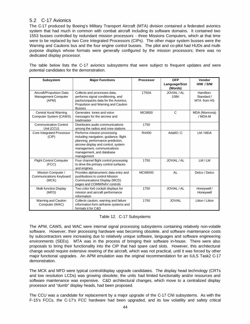
44
5.2 C-17 Avionics The C-17 produced by Boeing’s Military Transport Aircraft (MTA) division contained a federated avionics system that had much in common with combat aircraft including its software domains. It contained two 1553 busses controlled by redundant mission processors - three Missions Computers, which at that time were to be replaced by two Core Integrated Processors (CIPs). The other major system busses were the Warning and Cautions bus and the four engine control busses. The pilot and co-pilot had HUDs and multi-purpose displays whose formats were generally configured by the mission processors; there was no dedicated display processor. The table below lists the C-17 avionics subsystems that were subject to frequent updates and were potential candidates for the demonstration.
Subsystem Major Functions Processor OFP Language/Size
(Words)
Vendor H/W / S/W
Aircraft/Propulsion Data Management Computer
(APM)
Collects and processes data, performs signal conditioning, and packs/unpacks data for the Avionics, Propulsion and Warning and Caution Busses
1750A JOVIAL / AL 108K
Hamilton-Standard /
MTA from HS
Central Aural Warning Computer System (CAWS)
Generates tones and voice messages for the aircrew and loadmaster
MC6800 C MDA (Monrovia) / MDA-M
Communication Control
Unit (CCU) Distributes audio communications among the radios and crew stations
1750
Core Integrated Processor (CIP)
Performs mission processing including navigation, guidance, flight planning, performance prediction, aircrew display and control, system management, communications management, and database management
R4400 Ada83 / C LM / MDA
Flight Control Computer (FCC)
Four channel flight control processing to drive the primary control surfaces and engines.
1750 JOVIAL / AL LM / LM
Mission Computer / Communications Keyboard
(MCK)
Provides alphanumeric data entry and pushbuttons to control Mission Communications Display (MCD) pages and COMM/NAV controls
MC68000 AL Delco / Delco
Multi-function Display (MFD)
Two color 6x6 cockpit displays for mission and aircraft performance information
1750 JOVIAL / AL Honeywell / Honeywell
Warning and Caution Computer (WAC)
Collects caution, warning and failure information form airframe systems and formats it for C&D
1750 JOVIAL Litton / Litton
Table 12. C-17 Subsystems
The APM, CAWS, and WAC were internal signal processing subsystems containing relatively non-volatile software. However, their processing hardware was becoming obsolete, and software maintenance costs by subcontractors were increasing due to relatively unique software, languages and software engineering environments (SEEs). MTA was in the process of bringing their software in-house. There were also proposals to bring their functionality into the CIP that had spare card slots. However, this architectural change would require extensive rewiring of the aircraft, which was not practical, until it was forced by other major functional upgrades. An APM emulation was the original recommendation for an IULS Task2 C-17 demonstration. The MCK and MFD were typical control/display upgrade candidates. The display head technology (CRTs and low resolution LCDs) was growing obsolete, the units had limited functionality and/or resources and software maintenance was expensive. C&D architectural changes, which move to a centralized display processor and “dumb” display heads, had been proposed. The CCU was a candidate for replacement by a major upgrade of the C-17 CNI subsystems. As with the F-15’s FCCs, the C-17’s FCC hardware had been upgraded, and its low volatility and safety critical

45
software presented complex upgrade retest problems. The CCU was eventually chosen as the target domain for IULS Task 2 emulation. The CIP was under development (first flight was scheduled for Summer 1997) to replace the extant Mission Computers whose hardware was obsolete and overloaded. Software upgrades were going into both systems in parallel. A prime consideration in the selection of the avionics component to be used for the IULS demonstration was potential for transition to an EMD program. Specifically, the IULS goal was not only to demonstrate technology on a significant avionics upgrade challenge problem, but also to transition the technology to an emerging EMD opportunity. 5.3 Customer Upgrade Requirement 5.3.1 C-17 APM The APM was a prime candidate for the demonstration because it represented a domain of avionics subsystems that does internal data collection and formatting, and bridging of multiplex busses. It was essentially a state machine similar to the F-15’s AIU, but it did more processing for caution and warning generation including the calculation for a stall warning. It supported interactive maintenance mode formats on cockpit displays via the CIP, and supplied data to the C-17’s recorders.
FlightControl
Computer1-4
MissionComputer/
Communicat ionKeyboard
1 & 2
Aircraft/Propulsion
DataManagement
Computer1 & 2
WarningAnd
CautionComputer
1&2
Avionics Bus
Multiplex Bus
Discretes/Analogs
Centra lIntegratedProcessor
1&2(Or Mission
Computer 1-3)
ElectronicEngineControl
1-4WACS BusEngine Bus 1-4
FlightData
Recorder
AirborneIntegrated
DataSystem
• Electronic Flight Control System• Cabin Pressure Control ler 1&2• Environmental Control System• Aircraft Surfaces
Figure 32. APM Context Besides the Avionics and Warning And Caution System (WACS) 1553 MUXs, the APM had major serial interfaces via ARINC 573 with the Aircraft Integrated Data System (AIDS - maintenance data recorder), and via ARINC 429 with the Electronic Engine Controls (EECs), Flight Test Recorder (FTR), and Cabin Pressure Sensors/Controllers (CPSs). ARINC 422 channels were used with Engineering/Flight Development Units for aircraft testing. The APM received many analog sensor inputs for conversion such as AOA, control surface positions and acceleration; some were used for generating the stall warning discrete output to the pilot’s and co-pilot’s stick shakers. The following figure represents the major hardware components of the APM. They were contained on one “mother board” linked with local common address, memory and control busses.

46
GeneralProcessor
• 1750A
1553B• 8K RAM
Avionics Bus WACS Bus AIDS
ARINC 573Output
• 2 Channels
1553B• 8K RAM
Memory• 176K ROM• 32K ROM• 64K Dual
Port RAMMemory
Mgmt Unit
ARINC 429Outputs
• 7 Channels
FTR/EECs/CPSs
AnalogInputs
• 30 AC WithExcitation
• 6 DC
DiscreteOutputs
• 6 Outputs
DiscreteInputs
• 27 Inputs
ARINC 429Inputs
• 8 Channels• 16K RAM
ARINC 422I/O
Test
EECs
Address/Memory/Control
Figure 33. APM Hardware Configuration It was a special purpose processor whose architecture was customized for this application. The JOVIAL OFP including boot program were in the 176K static EEPROM. The 32K EEPROM was used to store aircraft fault data that was retained at power-off between flights. Early in Task 2 the IULS customer and the C-17 SPO were briefed on Task 2 plans for the C-17. The result of the Task 1 analysis for the C-17 avionics system was the recommendation of an APM upgrade demonstration. Several factors supported this recommendation. The OFP was well designed JOVIAL from Hamilton standard and Boeing had taken over doing software updates to the system. The C-17 project was considering an upgrade to the APM with the objectives of: • Mitigating the hardware obsolescence of the 1750 processor and other components, and replacing the
JOVIAL software and its SEE. • Migrating its features into the CIP as a general integration of federated subsystems. The Hybrid approach was ruled out since the APM has non-separable obsolete components and a software architecture that is customized for the hardware configuration. A rehost option was briefed as a possibility but not the preferred approach. The JOVIAL OFP could be rehosted and a JOVIAL compiler for the COTS target existed. However, the cost factors for a rehost indicated it was not the best solution. In addition, the F-15 demonstration was a rehost and better experience with the IULS tools would be obtained by using a different approach for the C-17. The recommendation for an APM upgrade demonstration was the emulate approach shown in the following figure. The APM was the most cost-effective candidate for this approach in the C-17. Its upgrade would serve as a model for the upgrades of other specialized C-17 and F-15 subsystems such as the Avionics Interface Unit. The Task 1 emulator analysis and modeling/simulation indicated that the approach was viable in terms of emulator and application resource usage on a COTS processor. A processor system and avionics test environment would be available for a “hot bench” demonstration at the C-17 engineering facility. The demonstration was tentatively planned for the first quarter of CY99.

47
C-17 DemonstrationPartial Emulation/Rehost On C-17 Avionics Bench
VMEbus
I/OSimulationARINC 422ARINC 429ARINC 573
Analog
Single Board Computer
LegacyComponent*
Wrapper
Discretes 2-1553
I/O Services
A/PDMC
Card Rack
IULSFramework
WrapperComponents
Emulator
GeneralProcessor
• 1750A
1553B• 8K RAM
Avionics Bus WACS Bus AIDS
ARINC 573Output
• 2 Channels
1553B• 8K RAM
Memory• 176K ROM• 32K ROM• 64K Dual
Port RAMMemory
Mgmt Unit
ARINC 429Outputs
• 7 Channels
FTR/EECs/CPSs
AnalogInputs
• 30 AC WithExcitation
• 6 DC
DiscreteOutputs
• 6 Outputs
DiscreteInputs
• 27 Inputs
ARINC 429Inputs
• 8 Channels• 16K RAM
ARINC 422I/O
Test
EECs
Address/Memory/Control
I/O Services
Ethernet
Green HillsMULTI
Wind RiverTornado
Workstation
* Candidate Rehost Components
•Stall Warning•Engine Fault Reporting
Figure 34. Planned C-17 APM Demonstration
It was also briefed that the scope of wrapping/emulating the complete A/PDMC OFP for C-17 was beyond the IULS program scope/budget. In particular, complete I/O emulation (discrete, analog, etc.) would drive the cost beyond available IULS funding. The recommended demonstration entailed a partial OFP (Engine Monitoring function) emulation. However, the recommended partial OFP emulation would be sufficient to assess the TRW emulator technology and verify the IULS process. In addition, the recommended program was scaleable to a full A/PDMC OFP demonstration, shown in the following figure, should funding become available in FY99.
C-17 Demonstration OptionTRW Replacement Emulation/Rehost On C-17 Avionics Bench
VMEbus
I/O Emulation2-1553
ARINC 422ARINC 429ARINC 573
AnalogDigital
Single Board Computer
Wrapper
Discretes Analogs
I/O Services
A/PDMC
Card Rack
Emulator
GeneralProcessor
• 1750A
1553B• 8K RAM
Avionics Bus WACS Bus AIDS
ARINC 573Output
• 2 Channels
1553B• 8K RAM
Memory• 176K ROM• 32K ROM• 64K Dual
Port RAMMemory
Mgmt Unit
ARINC 429Outputs
• 7 Channels
FTR/EECs/CPSs
AnalogInputs
• 30 AC WithExcitation
• 6 DC
DiscreteOutputs
• 6 Outputs
DiscreteInputs
• 27 Inputs
ARINC 429Inputs
• 8 Channels• 16K RAM
ARINC 422I/O
Test
EECs
Address/Memory/Control
I/O Services
A/PDMCOFP
SerialBusses
I/O Services
IULSFramework
WrapperComponents
TRWFramework
WrapperComponents
Wrapper
Figure 35. Optional C-17 APM Demonstration
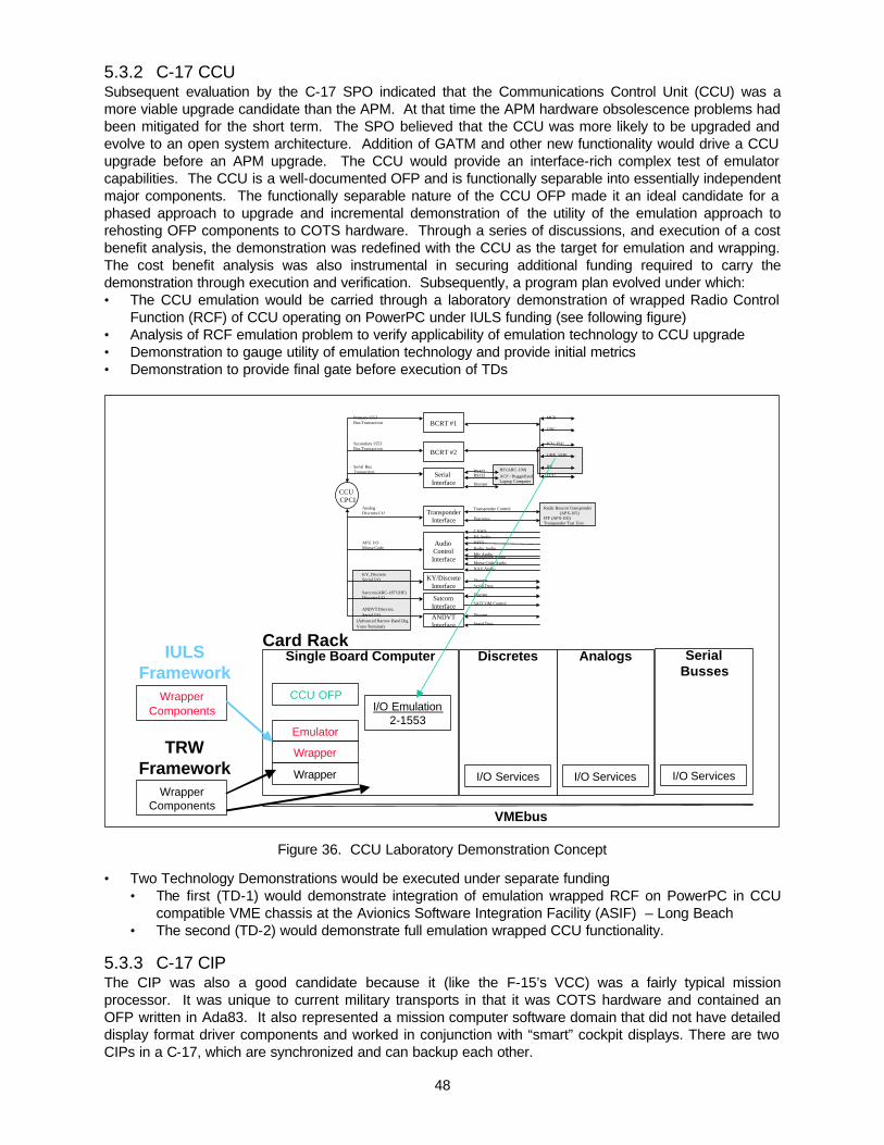
48
5.3.2 C-17 CCU Subsequent evaluation by the C-17 SPO indicated that the Communications Control Unit (CCU) was a more viable upgrade candidate than the APM. At that time the APM hardware obsolescence problems had been mitigated for the short term. The SPO believed that the CCU was more likely to be upgraded and evolve to an open system architecture. Addition of GATM and other new functionality would drive a CCU upgrade before an APM upgrade. The CCU would provide an interface-rich complex test of emulator capabilities. The CCU is a well-documented OFP and is functionally separable into essentially independent major components. The functionally separable nature of the CCU OFP made it an ideal candidate for a phased approach to upgrade and incremental demonstration of the utility of the emulation approach to rehosting OFP components to COTS hardware. Through a series of discussions, and execution of a cost benefit analysis, the demonstration was redefined with the CCU as the target for emulation and wrapping. The cost benefit analysis was also instrumental in securing additional funding required to carry the demonstration through execution and verification. Subsequently, a program plan evolved under which: • The CCU emulation would be carried through a laboratory demonstration of wrapped Radio Control
Function (RCF) of CCU operating on PowerPC under IULS funding (see following figure) • Analysis of RCF emulation problem to verify applicability of emulation technology to CCU upgrade • Demonstration to gauge utility of emulation technology and provide initial metrics • Demonstration to provide final gate before execution of TDs
VMEbus
I/O Emulation2-1553
Single Board Computer
Wrapper
Discretes Analogs
I/O Services
Card Rack
Emulator
I/O Services
CCU OFP
SerialBusses
I/O Services
IULSFramework
WrapperComponents
TRWFramework
WrapperComponents
Wrapper
CCU CPCI
BCRT #2Secondary 1553Bus Transaction
CNC
ICU, ISU
UHF, VHF
IFF
CCU
MCKBCRT #1
Primary 1553Bus Transaction
Serial Interface
RS232
Discrete
RS422Serial BusTransaction
Audio ControlInterface
ANDVTInterface
TransponderInterface
KY/DiscreteInterface
SatcomInterface
PA AudioPTTSRadio AudioMic AudioHeadphone AudioMorse Code Audio
Discrete
Discretes
CAWS
Radar Beacon Transponder(APX-105)
IFF (APX-100)Transponder Test Unit
APU I/OMorse Code
KY, DiscreteSerial I/O
ANDVT Discrete,Serial I/O
AnalogDiscrete I/O
Satcom (ARC-187 UHF)Discrete I/O
Serial Data
Discrete
SATCOM Control
Discrete
Serial Data
NAV Audio
Transponder Control
ACP / RuggedizedLaptop Computer
HF (ARC-190)
(Advanced Narrow Band Dig.Voice Terminal)
Figure 36. CCU Laboratory Demonstration Concept • Two Technology Demonstrations would be executed under separate funding
• The first (TD-1) would demonstrate integration of emulation wrapped RCF on PowerPC in CCU compatible VME chassis at the Avionics Software Integration Facility (ASIF) – Long Beach
• The second (TD-2) would demonstrate full emulation wrapped CCU functionality. 5.3.3 C-17 CIP The CIP was also a good candidate because it (like the F-15’s VCC) was a fairly typical mission processor. It was unique to current military transports in that it was COTS hardware and contained an OFP written in Ada83. It also represented a mission computer software domain that did not have detailed display format driver components and worked in conjunction with “smart” cockpit displays. There are two CIPs in a C-17, which are synchronized and can backup each other.

49
FlightControl
Computer1-4
MissionComputer/
CommKeyboard
1&2
Aircraft/Propulsion
DataManagement
Computer1&2
CentralIntegratedProcessor
1&2(MC 1-3)
Mission Bus 1&2
Multiplex Bus
Discretes
AirData
Computer
AutomaticFlight
ControlPanel
BearingDistanceHeadingIndicator
CentralAural
WarningSystem
Comm/Navigation
ControlPanel
DataTransferDevice
GlobalPositioning
System
Head-UpDisplay
InertialReference
Unit
RadarAltimeter
SpoilerControl/
ElectronicFlap
Computer1-4
MultifunctionDisplay
StationKeeping
Equipment
VOR/ILSMarkerBeaconReceiver
WeatherRadar
InterfaceUnit
AutomaticDirectionFinding
TacticalAir
Navigation
AerialDeliverySystem
Airframe/Engine
AnnunciatorDisplay
Unit
AvionicsSwitchingControlPanel
ControlStick
Assembly
MaintenanceInterface
Panel
Figure 37. CIP Context
The CIP hardware was a new unit from Lockheed Martin containing 6U VME cards in a VME-64 backplane/chassis with many spare slots. The initial configuration as shown in the following figure included a Computer Processor Module containing an R4400 and its OFP on SUROM, an Input/Output Processor also containing an R4400 with two 1553 Channels, and an Input/Output Module for discrete I/O.
ComputerProcessor
Module• R4400• DRAM• SUROM
Input/OutputProcessor
• Dual Channel 1553• R4400• DRAM• SUROM
Input/OutputModule
• Input Discretes• Output
Discretes
1553 Channel 1&2 Growth
VME64
Discrete I/O
Figure 38. CIP Hardware Configuration The CIP OFP was mostly Ada83 with some C driver components. It had been translated from the JOVIAL MC OFP, using a tool provided by Hughes. It contained the VxWorks real-time operating system (RTOS) from Wind River Software and was developed on Sun Workstations using a Rational host compiler and Green Hills target compiler. The CIP OFP’s major features were similar to those of combat aircraft OFPs. The major differences were that the CIP provided more navigation/guidance modes and flight/mission planning services that are typical of transport aircraft, but did not support weapon delivery.
CIP Features
• System Management and Monitoring • Communications Management • Navigation • Guidance • Controls and Displays

50
• Aircraft Performance Prediction • Flight Planning • Database Management • Data Interfaces • 1553 Busses • Discrete Interfaces
Potential C-17 Upgrades Which Affect CIP and APM Features • Traffic Alert and Collision Avoidance System (TCAS) • Autonomous Landing Guidance • Replacement of cockpit displays • MD-17 Commercialized Avionics • Global Air Traffic Management (GATM) avionics • Special Forces avionics Although the decision was made not to pursue a CIP upgrade using IULS tools the CIP eventually played a key role in the IULS Technology Demonstrations. As described below under TD-1 and TD-2, the decision was made to redefine TD-2 to focus on integration of the TD-1 hardware and software into the CIP. Results of these attempts are described under TD-2 below. 5.4 CCU Laboratory Demonstration The initial effort in support of the C-17 CCU emulation demonstration was the CCU Laboratory Demonstration which was executed under IULS funding to demonstrate the viability of the emulation approach to the CCU upgrade. The CCU Laboratory Demonstration included two phases: • In the first phase an analysis of the emulation of the RCF of the CCU was executed • In the second phase, emulation technology was applied to develop wrapper software for the RCF
function of the CCU and performance was demonstrated in a laboratory environment. As shown in the following figure, the program was structured such that successful completion of the domain analysis (Phase 1) was an entrance criterion for the demonstration phase (Phase 2). The figure also shows the various elements required for successful execution of the Phase 2 demonstration. Finally successful completion of the Phase 2 demonstration was specified as an entrance criterion for Phases 3 and 4.
< Phase 2 - Gate >
Radio ControlFunction
Demo
COTS Board Set
OTSEmulationProduct
COTS S/W
Exec, Drivers
Wrapper S/W(Develop. Item)
DomainAnalysis CCU
< Phase 1 - Gate >
Emulated
Radios
OFP BuildImage (V8.2)
Figure 39. CCU Demo Gates

51
5.4.1 Phase 1 The Phase 1 analysis consisted of the following: • Domain Analysis • Evaluation of the Utility of the Emulator • Develop Demonstration Plan. The domain analysis considered all CCU functionality, software and interfaces with major focus on the RCF functions. Particular attention was paid to the 1553 RCF functions and discretes. The analysis determined specific interfaces to be supported and functions to be emulated. The emulator evaluation was tightly coupled with the domain analysis since emulator capabilities and modifications were integral to decisions regarding scaling of the functionality to be emulated. The emulator evaluation identified required modifications to the TRW RePLACE tool and API, major risk areas and provided ballpark estimates of cost and schedule. TRW participated throughout the domain analysis in their role of emulator developer. The results of the domain analysis / emulator evaluation was a set of requirements for each demonstration phase which were executable within program resources. The consensus of the team was that the Phase 2 demonstration should focus on wrapping of the RCF with simulated 1553 interfaces and radios. The demonstration should be executed at the C-17 SPO. Phase 3 would deliver a ruggedized PowerPC system and emulation wrapping with real vice simulated 1553 interface devices (radios). Phase 4 would deliver a wrapped CCU system with audio and radio control functions on a ruggedized PowerPC. The Phase 3 and 4 demonstrations would be executed in the AIA at Long Beach. A top-level description of the content of the three demonstrations is shown in the following figure. The figure includes changes in content which are discussed under TD-1 and TD-2 below.
Elements Phase 2 TD-1 TD-2COTS Board Set PowerPC, Dual 1553 PowerPC, Dual 1553,
Discrete IO cardPowerPC, Dual 1553,Discrete IO card, CIP
COTS S/W VxWorks RTOS,Tornado IDE
VxWorks RTOS,Tornado IDE
VxWorks RTOS,Tornado IDE
OTS Emulator RePLACETM v1.1,VIEWstation™ v1.0
RePLACETM v1.1,VIEWstation™ v1.0
RePLACETM v1.2,VIEWstation™ v2.0
Wrapper S/W 1553 I/O, Discretesmemory mapped
1553 I/O, Discrete I/O 1553 I/O, DiscreteI/O, Integration intoCIP
OFP Build Image Version 8.2 Version 8.2 Version 8.2
Radios Simulated UHF &VHF only
Real UHF, VHF, HF,ARC-210, IFF
UHF, VHF, HF, ARC-210, IFF, APX-105
Audio None None (provided by 2nd
CCU)None (provided by 2nd
CCU)
Discretes Simulated Real Real
Controls &Displays
MCK/MCD emulatedon PC, no CNC, ICS
Real MCK/MCD, realCNC, ICS
Real MCK/MCD, realCNC, ICS
Demo Event Radio Control thread Redlined 80% RadioControl SIT
Redlined 85% RadioControl SIT operatingin CIP
Figure 40. Demonstration Definition
The output of the domain analysis / emulator evaluation were used to develop the demonstration plan. The team conclusion was that the problem was low risk within the schedule and budget available. The demonstration plan defined the approach for demonstrating and testing emulated functions including test signal collection needs and simulation approach. The plan defined the content of the demonstrations in the following areas: interfaces, functions, displays, risk. It included a task schedule and critical path analysis. The schedule and top-level content are shown in the following figure. As described below, the content and

52
dates for TD-1 and TD-2 changed in response to programmatic influences. These changes are reflected in the figure.
1998
• Domain Analysis• Demo Plan
DomainAnalysis
Phase 2Demo
TD - 1
TD - 2• MCK/MCD Control• UHF, VHF
(simulated)• Aircrew Laptop
Computer DatabaseDownload
• Fault Mgmt
• Dual CCU• All Radios (real)• CNC & ICS• Redlined Radio
Control FQT
• Radio Control Integrated intoCIP
• Redlined Radio Control FQT
C-17 SPO C-17 SPO Long Beach
19993/12 8/31 12/31
Transition toProposedOpen SystemEnd StateArchitecture
Long Beach
IULS TD Program
Figure 41. Demonstration Schedule The results of Phase 1 were reviewed with the IULS and C-17 customers and it was agreed that the program should enter Phase 2. 5.4.2 Phase 2 The Phase 2 demonstration was designed to verify applicability of the IULS emulator technologies and processes to the C-17 CCU domain. Exercise of limited CCU functionality and a subset of the external interfaces was established as an entrance criterion for development of a more complete solution under the Weapon System Software Technology Support (WSSTS) contract. The WSSTS effort would include Phases 3 and 4 of the demonstration. Phases 3 and 4 are also known as C-17 Technology Demonstrations 1 and 2 or TD-1 and TD-2. The focus of Phase 2 was to demonstrate emulation of MIL-STD 1553 I/O including emulated UHF and VHF radio control. The ability to communicate over the RS-232 interface was also a demonstration goal. The following figure provides a logical view of the C-17 Integrated Radio Management System (IRMS) with the Phase 2 demonstration elements shaded. The MCK/MCD elements are the Mission Control Keyboard and Mission Control Display, which were emulated in the demonstration and used to exercise the MIL-STD 1553 interface.

53
APX-105
ARC-210 #1
TACAN
Radio (UHF1)
IFF
NAV (PLSR or..)
ANDVT
P.A.
NAV (PLSR or..)
Radios (HF)
Radios (VHF2)
ARC-210 #2
ADF Rcvr
BCRT
BCRT
BCRT
BCRT
CCU NO. 1
CCU NO. 2
AudioDiscrete/
Analog
Discrete/AnalogAudio
CNC
CNC
ARC-210RCU
MCKMCD
MCD
MCD
MCDMCK
ICSs
ICSs
ISU
ISU
MSN1553
MSN1553
1553(COMM 1 BUS)
1553(COMM 2 BUS)
HeadPhonesTypical(1 of 9)
Figure 42. C-17 IRMS Elements Demonstrated in Phase 2 (Logical View) In the Phase 2 demonstration configuration, a commercial VME Chassis containing a PowerPC 603e with Ethernet, 200 MHz Dual 1553 and single-channel RS-232 interfaces acted as CCU No. 1. The CCU Legacy OFP wrapped with TRW’s RePLACE 1750 Emulator executed on the VME-enclosed PowerPC. A laptop computer was tied into the RS-232 interface to support Aircrew Laptop Computer (ALC) Database Download. A separate PC, which acted as the MCD/MCK emulator, was tied into the MIL-STD 1553 interface. Another laptop was tied into the MIL-STD 1553 interface and connected to the VME Chassis by Ethernet. This latter laptop executed TRW’s VIEWstation Debug Toolset. UHF and VHF radio control was emulated using the PASS-3000 1553 Bus Emulator. The physical view of the Phase 2 Demonstration Configuration is shown in the following figure.

54
PASS-30001553 BusEmulator
Radio (UHF1)
Radios (VHF2)
BCRT
BCRT
CCU NO. 1
CCU NO. 2
RS-232
Ethernet
Aircrew Laptop Computer(ALC) Database Download
TRW'sVIEWstation™Debug Toolset
MCD
MCDMCK
MCD1
MCD2
MCK/MCD Emulator
Not Present
VME ChassisPowerPC 603e, 200 MHzDual 1553 VME Interface
VxWorks RTOS
NativeEnviron.
Leg
acy
En
viro
nm
ent
ISAµcode
I/OEmul.S/WV
irtu
al C
om
p. E
nvir
.
TRW's RePLACE™1750 Emulator
CCU Legacy OFP
COMM1
COMM2
Figure 43. Phase 2 Demonstration Configuration (Physical View) The Phase 2 Demonstration executed a subset of CCU OFP functionality selected to satisfy the objective of validating the emulation approach on an expedited schedule. The following figure shows CCU OFP Components and indicates the extent to which they were exercised in the demonstration.
IO $PROC
FLT $MNGNT
ICS $PROC
AUDIO $PROC
EXEC
RADIO $CTRL
CNC $PROC
BIT $PROC
SHUT-DOWN
START-UP
MCK $PROC
DSP $MNGR
POWERWARNINGSTATUS
NVRAM
NVRAM
CCU FAULT STATUS
TEST SEQUENCE
OFFLINEFAULTSTATUS
ONLINEFAULT STATUS
ANALOGDISCRETES
RS422
RS232
1553
INPUT AREDISPLAY
PARAMETERS
INPUT ARERADIO CONTROL
DATA
RADIOOUTPUT
DATA
CNCREQUEST
ICSREQUEST
INITIATED BITSEQUENCE
TESTSEQUENCE
AUDIOCONTROL
DATA
APUsOUTPUT
DATA
MCKREQUEST
INPUTQUEUES
MCKOUTPUT
DATA
Information Flow Diagram (from CPDS)
CPC Bypassed
CPC Not Exercised
CPC Exercised
DatabaseUpload
Figure 44. CCU OFP Architecture Components
The primary concern regarding emulator performance was in the area of I/O. The bulk of the modification to the existing 1750A emulator performed to support the Phase 2 Demonstration were in this area. The following figure provides an overview of the emulator I/O used in the demonstration.

55
• I/O Device Objects Written:– BC1553 RT1553 BCRT Discretes– Audio Discretes ANDVT Discretes KY Discretes– Analog Transponder SATCOM Discretes Serial IO– SBC Discretes
• Status of I/O Devices– Completed Fully Functional 1553 Bus Controller Device Class (RT Class
implemented, to be tested in next phase w/dual CCU)– Completed Fully Functional Serial IO Class– Stubbed Out Most Discretes with Static Values
• OFP Code that has been bypassed with "thunks"– Startup02 Replacement 0x01140 0x00002– IBit01 Replacement 0x02F79 0x00157– RegReadbk01 Replacement 0x022EA 0x00049– XIOREDBLACK Replacement 0x0105F 0x0000A
Figure 45. Overview of Emulated I/O The demonstration procedure entailed 8 steps: • Loading of Emulator and CCU OFP • Cold Startup of CCU OFP • Operation of MCK/MCD using MCK/MCD Emulator • Uploading of Comm Database from Aircrew Laptop Computer • Reviewing of Comm Database on MCD • Viewing UHF/VHF Radio Control 1553 Data • Reviewing Fault List on MCD • Viewing Emulator Performance The Phase 2 demonstration was performed at the C-17 SPO on 12 March 1999. The following functions were demonstrated: • Mission Control Keyboard (MCK) / Mission Control Display (MCD) operation – verified the ability to
communicate on the MIL-STD-1553 bus • Communications Database uploading – verified the ability to communicate over the RS-232 interface • Display uploaded Communications Database – verified the ability to use uploaded database
information • Control an emulated radio – verified the ability to communicate with devices on the MIL-STD-1553 bus • Demonstrate status functionality. There were several lessons learned from the demonstration: • Lack of discrete interfaces & real hardware devices requires carefully tweaking stubbed out discretes
& careful modeling of some of them • Having LRU/OFP domain expertise on-site during integration will accelerate the effort • Adequate time should be allocated to assemble & checkout the various components of the test
environment • Care should be taken to ensure that the OFP and its documentation are consistent (same version).
This can be a quite common problem when very old legacy software is used, and the documentation has not kept up with the pace of software changes
• Getting the OFP up & running can be successfully accomplished in a very short time period after i/o devices have been completed (2-3 weeks in this case).
The demonstration made to the C-17 SPO was a major success. The program was described by Chris Blake (then Technical Director) "This is great work...(to AFRL) your 6.3 funding will get even tighter, but we can't let go of this one...(to Boeing) I'm offering to be your launch customer...(to Hartman - Chief Systems Engineer) let's make this happen."

56
Following the execution of Phase 2, initiation of the Technology Demonstration Program (Phases 3 & 4) was approved. The major areas of risk were all considered low after completion of the demonstration, as shown in the following figure.
Risk Factor Severity Mitigation Plan
Fidelity OfEmulationIncluding TimingDependent Code
Low -Moderate
§ Analysis Of OFP And Utilization OfThunks & Wait Loops – 4 thunks installed§ Addressed During Phases 2 & 3
AdequateThroughput ForEmulator, I/ OWrapper, & NewC CodeFunction(S)
Low –Moderate
§ Emulator Measured <=10% Of AvailableThroughput;§ I/ O Wrapper Performance To Be
Measured In Phase 2 (< 15% Expected)§ Emulator running at 6.5 MIPS w/ IO
wrappers (~ 85% excess margin)§ Audio Code Performance To Be
Measured & Used To Project OS-CCUPerf. ( < 25% Expected) not needed§ Addressed During Phases 2,3,4
Interfacing New CCode To ExistingJovial Object Code
Low § CCU OFP Is Well Structured With LogicalInterface Boundaries Between Functions;§ Debug Toolset Assists User In Hooking
Into Legacy Code§ Addressed During Phase 2
Figure 46. Post Demonstration Risk Assessment
5.5 C-17 Technology Demonstration 1 (TD-1) IULS TD-1 built upon the success of the Phase 2 demonstration. TD-1 was designed to accomplish all objectives of the Phase 2 Demonstration, but in a more realistic environment and with additional functionality. Significant changes from the Phase 2 Demonstration to TD-1 included: • Emulator and CCU OFP operation in a workstation environment
• Emulator and CCU OFP operations in COTS Replacement Box (CRB) environment • CRB Connected to the IRMS Subsystem Evaluation Station in place of either CCU
• Operation of MCK/MCD using MCK/MCD Emulator • Operation with both real and emulated MCK/MCDs • Operation of CRB with actual C-17 Line Replaceable Units (LRUs) including second CCU, ICS
panels, CNC panels and radios • Uploading of Communications Database with current or follow-on ALC • Reviewing Communications Database on MCD
• Preset selection and loading for all radios including SATCOM • ARC-210, UHF, VHF, HF, and IFF Radio Control
• Discrete wires individually control power and antenna selection for each radio • Reviewing fault list on MCD
• Fault History recorded and displayed identically to second CCU • Interactive and non-interactive Build-In-Test controlled by CRB for each interfacing LRU
• Audio functions undisturbed in second CCU • CCU 2 controls audio routing for all radios
• CIP/CCU/CRB 1553 handshake undisturbed

57
• EMCON, TACAN, ADF function normally The following figure gives a logical view of the CCU Demonstration Plans for TD-1 and TD-2. The Phase 2 Demonstration is included for reference. As can be seen from the figure each of the TDs add to the demonstration content. It should also be noted that this logical view does not tell the complete story. For instance, CCU No. 1 appears the same for the Phase 2 Demonstration and TD-1 on the logical view. In actuality, the TD-1 implementation was of higher fidelity in this area as described below in the discussion of the COTS Replacement Box.
APX-105
ARC-210 #1
TACAN
Radio (UHF1)
IFF
NAV (PLSR or..)
ANDVT
P.A.
NAV (PLSR or..)
Radios (HF)
Radios (VHF2)
ARC-210 #2
ADF Rcvr
BCRT
BCRT
BCRT
BCRT
CCU NO. 1 - PowerPC
CCU NO. 2 (Real CCU)
AudioDiscrete/
Analog
Discrete/AnalogAudio
CNC
CNC
ARC-210RCU
MCKMCD
MCD
MCD
MCDMCK
ICSs
ICSs
ISU
ISU
MSN1553
MSN1553
1553(COMM 1 BUS)
1553(COMM 2 BUS)
HeadPhonesTypical(1 of 9)
Phase 2, TD-1&2
TD-1, TD-2
TD-2
Functional Audio
CIP
Figure 47. CCU Demonstration Plan (Logical View) The IULS TD Program was structured with TD-1 as a gate for TD-2. The following figure depicts this gate structure along with the principal elements of TD-1.

58
Add. CCU FCNs(Audio)
Demo
Open S/W
< Phase 2
Gate >
< Phase 3 - Gate >
Radio ControlFunction
Demo
OTSEmulationProduct
COTS S/W
Exec, Drivers
Wrapper S/W(Develop. Item)
Real Radios
OFP BuildImage (V8.2)
COTS Board Set
Qual Test
CCU Interfaces
Figure 48. CCU Demo Gates A key element of TD-1 was the CCU COTS Replacement Box (CRB). The CCU CRB is a computing device capable of functionally emulating either legacy CCU LRU. The rear panel of the chassis holds connectors, which provide connection to the CCU I/O signals. The CCU CRB also connects to a Personal Computer (PC) known as the CRB User Console that executes download, test, and control software. The PC connects to the CRB via both Ethernet and RS-232 connections. A critical component of the CCU CRB is the processor board, which executes the RePLACE 1750A Dual Instruction Set Computer (DISC) software and the CCU OFP. The processor board is a SP-103 Lockheed Martin Federal Systems (LMFS) PowerPC 603e 200MHz single board computer housed in a VME64 chassis. The CCU CRB contains I/O interface boards to provide the I/O signals required for emulation of the legacy C-17 CCU. The I/O interface boards send and receive the same signals as the legacy C-17 CCU LRU so that the CCU CRB can serve as a functional drop-in replacement for the C-17 CCU LRU. The CCU CRB communicates with an external PC used as a User Console. The User Console acts as a file server, providing software and data files needed by the CCU CRB. The User Console also downloads and starts the CCU CRB software. The CRB replaces the commercial VME Chassis, PowerPC and interfaces used in the Phase 2 Demonstration. The following figure shows the TD-1 Demonstration Configuration. Comparison with the Phase 2 configuration, shown previously, highlights many of the changes. The figure shows: the availability of dual MCK/MCD’s vice the emulated MCK/MCD used in the Phase 2 demonstration, utilization of the MCK/MCD to host the VIEWstation toolset and perform the ALC Database Download, single or dual CCU configuration, and the inclusion of real radios. Not visible from the figure is the contribution of the CRB. The CRB includes the VME Chassis etc and supports testing of the radio discrete interfaces.

59
Radio (UHF1)
Radios (VHF2)
BCRT
BCRT
BCRT
BCRT
CCU NO. 1
CCU NO. 2
NoAudio
Disc.I/O
Disc.I/O
NoAudio
Aircrew Laptop ComputerDatabase Download
VIEWstation™Debug Toolset
Legacy CCU
VME ChassisPowerPC SP-103, 200 MHzDual 1553 InterfaceDiscrete I/O VME I/F
VxWorks RTOS
NativeEnviron.
Leg
acy
En
viro
nm
ent
ISAµcode
I/OEmul.S/W
Vir
tual
Co
mp
. En
vir.
1750 Emulator
CCU Legacy OFP
COMM1
COMM2
MCD
MCDMCK
MCD1
MCD2
1st MCK/MCD
ARC-210 #1
IFF
Radios (HF)
ARC-210 #2
MCD
MCDMCK
MCD1
MCD2
2nd MCK/MCD
CNC
ICSs
CNC
ICSs
Figure 49. TD-1 Demonstration Configuration TD-1 was completed in August 1999. The following items were demonstrated: • Operation of CRB acting as a single CCU • Dual CRB – CCU operation • Communications Database upload with current and follow-on ALC • Operations with MCK/MCD, CNC, ICS • Operations with all radios (ARC-210, UHF, VHF, HF) and IFF • Audio control and switching with CRB and second CCU controlling audio as “Alternate” Initial bench-marking performance indicated 6.0 MIPS compared to 6.5 MIPS at March demonstration, largely due to additional processing. This represents approximately a 90% reserve above the legacy 1750A processor. There were no major anomalies during the testing. Four minor anomalies were observed and were subsequently dispositioned. The decision was made to proceed with TD-2. 5.6 C-17 Technology Demonstration 2 (TD-2) By the time of initiation of TD-2 the demonstration had undergone considerable redefinition. The original plan (12/98) had been to add TCOMMS Audio Switching in TD-2. Before initiation of TD-1, this plan had been revised. Audio switching was eliminated because of Telephonics costs and interface to the APX-105 Transponder was added. The original approach emphasized use of Telephonics TCOMMS software to perform the audio switching function, and the use of emulation for the remaining radio control functions. Audio switching functionality costs based on integrating off-the-shelf TCOMMS software were substantially above available funding and made this original element of TD-2 impossible to execute. As an alternative, Boeing Long Beach recommended (and we received C-17 SPO concurrence) to replace audio functionality with execution of CCU functionality by integrating CCU COTS processor into the CIP. The rationale for these changes were the non-recurring costs for the audio switching and the C-17 Program interest in CIP integration as a potential end-state. The TD-2 kick-off was held following the TD-1 demonstration on 26 August and served to re-prioritize some of TD-2 activities following the success of TD-1. The priorities were developed jointly by the C-17 SPO and the C-17 program at Long Beach and were selected to better enable C-17 to incorporate results of the Tech Demo program in their C-17 Open Systems Communication architecture study. Specifically, the following priorities were made: 1) Transition CCU OFP baseline from 8.2 to 8.3; 2) Incorporate emulation

60
wrapped OFP into CIP; 3) Incorporate C language fixes to 8.3 software into the emulation wrapped OFP; 4) Investigate ANDVT. The incorporation of APX-105 radar transponder was viewed by C-17 as of only limited utility, since during TD-1 we have already demonstrated interface of wrapped software with a wide variety of other 1553 devices. Initial integration for TD-2 was conducted at Long Beach on 27 - 30 September 1999. The activity included: 1) Incorporation of CCU OFP baseline 8.3 into the CRB; and, 2) Initial CIP integration of SP-103 and discretes into the CIP. The upgrade of CCU baseline from 8.2 to 8.3 proceeded very smoothly. Initial integration of the CRB components into the CIP did not go as smoothly as desired. The SP-103 was successfully integrated into the CIP using a VME extender card. However, the CIP was not able to work with both the SP-103 and the discrete I/O boards installed on VME extenders in the CIP chassis. Specifically, the CIP would either go into a degraded mode or not work at all with more than one extender card in the chassis. This appeared to be due to system losses as the bus was extended. Lockheed Martin CIP personnel at Long Beach reported that was also their experience. Also, the VMETRO VME bus analyzer tool did not fit within the channel guide. The discrete boards and VME repeater boards had card layouts that allowed component contact with the chassis. To accommodate operation in the CIP, the discrete card layout would need to be modified to utilize less board space. This may or may not be a problem with ruggedized COTS discrete I/O boards. Boeing and TRW developed two plans in response to work around the CIP chassis limitations: 1) Plan A; and 2) Plan B. The plans were documented in the minutes of a TIM held on 7 October in Dayton. Through subsequent evaluations, Plan A was identified as the preferred approach. The following figure shows the approach for plan A. Briefly, the SP-103 board would be installed in the CIP chassis. A VME Repeater Master card would be installed in the CIP and connected with a "Slave" card in the CRB. The discrete I/O boards would be installed in the CRB. In essence, this is the same arrangement as a CIP integration (assuming that ruggedized discretes would fit within the chassis).
IMPLEMENTATION PLAN “A”VME Repeater Master - Slave
POWER
I/O
IOP
CPM
SP103
VME
RPTR
ARCOMAG
CIP
VME
RPTR
CRB
ARCOMAG
ARCOMAG
LM SP-103 Moved from CRB to CIPOperating on Extender
VME Repeater “Master” installed in CIP. “Slave” in CRB.
All VME bus arbitration occurs in CIP Chassis
Figure 50. CRB CIP Integration Plan
Boeing performed a second integration of the wrapped Radio Control Function (RCF) in the CIP starting 1 November. The November integration activity used Plan A from the October TIM. The second integration activities proceeded with limited success largely due to the somewhat non-standard VME nature of the CIP. TRW and Boeing discussed the integration issues with the CIP vender. The vendor indicated: 1) Need for current SP-103 drivers; and 2) Need to cut traces in the CIP backplane. Given these, they indicated that they believed the integration would work.

61
Most important, Boeing IULS personnel met with Boeing C-17 personnel relative to the communication open architecture study and to CIP integration progress. They described their efforts in CIP integration and relayed to the C-17 personnel the results of the telecon with the CIP vender. Boeing C-17 indicated that he could possibly get a spare CIP chassis to use to implement the vender suggestion. They also indicated that Boeing C-17 no longer consider integration into the CIP as either a mid or short-term objective. Instead they viewed it as a very long term (C-17B) type of goal. Based on this significant C-17 change of philosophy, the IULS TD program decided that it no longer made sense to pursue integration activities with the CIP - since the transition story had for practical purposes evaporated. Instead, tech demo efforts focused on evaluation of the emulation tool by C-17 personnel - especially in its support of incorporating new C++ software. Specifically, we believed that for a tech transition story to have real longevity, it would be necessary to not simply emulate a legacy system - but also to demonstrate how the system could support new functionality developed using modern languages including C and C++. Following initial RePLACE training by TRW, Boeing S/W engineering personnel initiated their development of the C-language software update to CCU OFP version 8.3. They continued their efforts, and were able to incorporate their update into the wrapped RCF. The software engineers wrote a draft report discussing their observations on use of the emulation toolset. The report indicated that the engineers were able to accomplish their job without difficulty. The report also provided both positive observations on the toolset, but also indicated some desired updates. It also indicated that successful use of the tool required domain expertise. Some potential hardware problems with the CRB were reported by the engineers who were working the C-language update. These problems have been resolved, and were indicated to be AISF related, and were not CRB problems. The final disposition of TD-2 is: • Ease of incorporating update of legacy Jovial OFP from 8.2 to 8.3 was demonstrated
• Less than one day of activity • Successfully executed subset of System Integration Test (SIT)
• Successful execution of C-language update of Jovial Code • Boeing C-17 developed challenge problem • Training on emulator provided by Boeing IULS team to Boeing C-17 software developers • Code developed and initial testing by Boeing C-17 in ASIF • Successful employment of technology demonstrated
• Oct 99 integration • COTS Discrete cards did not fit in CIP chassis (impinged on wedge locks) • PowerPC and Discretes on Extender Board in CIP • CIP operated in degraded mode • Probable cause losses as bus extended • Coincides with CIP vender experience
• Nov 99 integration • PowerPC on extender board in CIP • Discretes in CRB • Bus conflicts • Boeing/CIP vender discussions indicated cutting of traces for backplane and installation of latest
PowerPC driver probably required but could be made to work • CIP date preceded VME-64 bus standardization
• C-17 Program and IULS Team Meeting indicated CIP incorporation of RCF no longer in near / mid-term plan
• CIP integration efforts suspended 5.7 C-17 Communications Open System Architecture (COSA) The C-17 program embarked on the COSA program during the summer of 2000. Figure 51 shows a COSA program history.

62
1998 1999
PTP-077GATM Initiatives
8 Jan 98
Revised PTP-077GATM Initiatives
24 Apr 98
•GATM - CPDLC, ADS-A,TCAS, CMU, AERO-I, APX-100 Mode S•IRMS - Legacy CCU analog audio update - Modified ICS - No CNC changes - No HRP changes
•~$85M development total
•GATM - CPDLC, ADS-A,TCAS, CMU, AERO-I, APX-100 Mode S•IRMS - Legacy CCU unchanged - ICS, CNC unchanged - P/CP HRPs modified, SAT audio panel added - CCU controls Mode S - CIP controls AERO-I
•~$61M development total
PTP-077SRR/JCB
May - Jun 98
•AMC / SPO concernedby non-integrated GATMsolution•Recommended launch ofseparate OSA project forIRMS•Nov 97 architecture asbaseline
COSA StudyMay - Dec 99
C-17 AvionicsPhase I OSA Study
Aug - Dec 98
•OSA CCU - Digital Audio - Radio Control in CCU•OSA CNC•OSA HRP•COSSI ICS•Sat audio panel deleted•No 1553 bus architecture change
Figure 51. COSA Program History
The COSA study concluded in December 1999 and resulted in the initiation of an ECP for implementation of an open architecture upgrade of the C-17 communications system. Telephonics, the producer of the current legacy CCU, was selected as the lead subcontractor. Key elements of the COSA program are identified in the figures below.
o System upgrade of the existing Integrated Radio Management
o OSA CCU/Audio Control Unit replaces legacy CCUlIncorporates digital audio
lProvides secure communication operations at all stations
lSystem control functions remain in the CCU
—1553 bus control
—Radio selection, operation, and control
—MCD user interfacelMitigates DMS/obsolescence
lExpansion capability to support future requirements
—GATM Enhancements
—VHF Data Link
—Real Time Information in the Cockpit
Figure 52. Key COSA Program Features Additional key COSA elements are: 1) 1553 Bus Architecture remains unchanged with no impact to mission bus loading and address usage; 2) Upgraded CNC and ICS control panels to “soft panel” configuration; and 3) CIP functions remain unchanged. These latter changes were consistent with the IULS TD decision to abandon integration of CCU functionality into CIP. The final issue in the COSA program was the role of
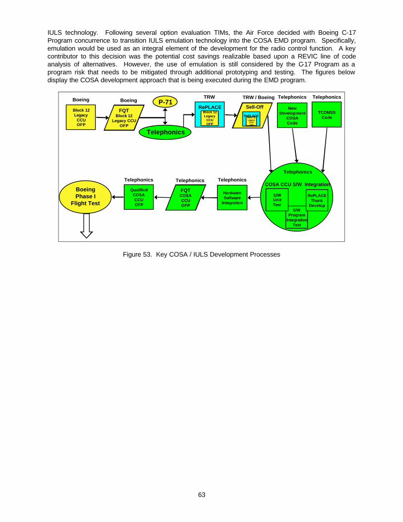
63
IULS technology. Following several option evaluation TIMs, the Air Force decided with Boeing C-17 Program concurrence to transition IULS emulation technology into the COSA EMD program. Specifically, emulation would be used as an integral element of the development for the radio control function. A key contributor to this decision was the potential cost savings realizable based upon a REVIC line of code analysis of alternatives. However, the use of emulation is still considered by the C-17 Program as a program risk that needs to be mitigated through additional prototyping and testing. The figures below display the COSA development approach that is being executed during the EMD program.
BoeingPhase I
Flight Test
Block 12Legacy
CCUOFP
Boeing
FQTBlock 12
Legacy CCUOFP
Boeing P-71
Telephonics
TRW
Sell-Off
TRW / Boeing
NewDevelopment
COSACode
Telephonics
HardwareSoftware
Integration
Telephonics
TCOMSSCode
Telephonics
FQTCOSACCUOFP
Telephonics
QualifiedCOSACCUOFP
Telephonics
RePLACEBlock 12Legacy
CCUOFP
RePLACEBlock 12Legacy
CCUOFP
S/WProgram
IntegrationTest
Telephonics
COSA CCU S/W Integration
RePLACEThunk
Develop
S/WUnitTest
Figure 53. Key COSA / IULS Development Processes

64
P-108
Block 14HFDL
Requirements
Boeing
Phase IFlightTest
Results
Boeing
SoftwareChangeAnalysis
Block 14New
DevelopmentCOSACode
Telephonics
Boeing &Telephonics
HardwareSoftware
Integration
Telephonics
FQTCOSACCUOFP
Telephonics
Block 14Legacy
CCUCode Modify
Boeing
Block 14Legacy
CCUOFP
RePLACE
Telephonics,Boeing, TRW
QualifiedCOSACCUOFP
Telephonics
SoftwareChangeAnalysis
Boeing &Telephonics
S/WProgram
IntegrationTest
Telephonics
COSA CCU S/W Integration
RePLACEThunk
Develop
S/WUnitTest
BoeingPhase II
Flight Test
AISFUpgrade
(Block 16)
BoeingPhase I
Flight Test
Boeing
Figure 54. Key COSA / IULS Development Processes (Cont.)
These figures demonstrate the key role that IULS emulation engine will have in the COSA program. 5.8 C-17 Summary The C-17 IULS transition is a work in progress. Our experience indicates that transition can be difficult but is achievable. Successful transition requires perseverance, patience, as well as an opportunity to perform. In IULS, we started down the tech transition path with the C-17 program as our partner. As a team, we changed demonstration challenge problems to select one that was most relevant to the C-17 and had the greatest potential to transition to EMD. We launched the IULS tech demonstration program using a carefully structured four phase approach. The first two phases were executed under the IULS program. Entry into phase 3 was conditional upon receiving approval of the C-17 program. The phase 2 demonstration was an unqualified success. It received high praise from the customer, and the decision was made to proceed to Phase 3 to demonstrate the utility of IULS emulation in the C-17 avionics labs. The demonstration provided a first cut shake out of emulation technology and indicated significant promise. At the end of phase 2, the C-17 Technical Director was re-assigned to work on the F-22 program. In a sense, IULS program lost one of its greatest technology transition backers when the TD left. The lesson is that tech transition to some degree is also driven by advocacy at the top of the production program, and is not simply driven by technology success or maturity. Phases three and four of the tech demonstration program were executed on cost and on schedule with very positive results obtained by execution of existing C-17 test procedures using the CRB. Even with this success, the transition remained in the balance. Production programs are by their very nature risk averse. New technologies such as those offered by IULS are seen as potential risks - even when their performance has been proven. Before IULS technology was selected for COSA, a number of options were considered and an exhaustive trade study was performed. IULS program was a key participant in these studies, and we were able to successfully make the case that emulation technology was ready for prime time and should have an important role in the COSA EMD program. One of the central arguments that was made was that use of
65
emulation is a risk mitigator. Re-engineering of the proven legacy code would be costly. We estimated using REVIC that utilization of IULS emulation technology could potentially save the COSA program on the order of $3M. This estimate was based on comparing costs for re-engineering into C/C++ approximately 30,000 lines of code vice emulating the function using the RePLACE emulation engine. This argument was persuasive and was important not simply from a cost perspective - but more from a risk perspective. The customer may save money by using emulation - but counts it more as a reserve against program risk. One of the important factors to consider is that in this IULS technology transition, Boeing had key roles as both the technology customer (C-17 program - Long Beach) , and the technology evaluator (IULS prime). This provided us visibility into the technology transition selection process that would have been impossible otherwise. This same opportunity would have likely been not available to an outside technology developer attempting to transition technology to the production program. Some other thoughts are germane to transition of emulation technology to a production program. We must first remember that IULS is all about incremental upgrade. It is about steps along a migration path to an open system and taking advantage of existing legacy software. In the C-17 COSA program, the customer needed to balance their desire to make a radical open system architecture upgrade with realities of program risk. As originally bid by Telephonics, COSA envisioned a complete re-engineering of CCU software. Telephonics did not intend to utilize any legacy software in their update. The C-17 program was convinced that an incremental approach afforded them a better short term solution, provided a less risky transition path to the desired open system end state, and allowed them to utilize a substantial investment in legacy software. The COSA program is taking a novel approach to the use of the legacy software that needs to be considered as the IULS emulation model evolves. Specifically, rather than starting with a legacy executive and calling new native functionality, COSA is building a new native executive to call selected elements of the emulated legacy software. While this might be considered a riskier approach, it represents the C-17 program perspective of marching toward the future, and the emulation engine needs to adapt and support this type of approach. The lesson is that in the technology transition, the customer is the architect of the design and will be using tools in ways that may not have been originally intended. Failure of the technology to perform as designed even in the face of new applications can forestall the technology transition. Also, in some instances the failure may be due to poor or not maintained legacy software design in the first place.
66
6 Perimeter Attack Radar Characterization System Analysis The Perimeter Attack Radar Characterization System (PARCS) is a one-of-a-kind sensor system, developed in the early 1970s for the United States Army Safeguard Ballistic Missile Defense System by the Western Electric Company, a part of Bell System at the time. The original system design called for twelve sites, and the system’s logistic support was planned with that in mind. With the signing of the anti-ballistic missile treaty between the United States and the Soviet Union, full development of the Safeguard system halted. The PARCS site, at Cavalier, N.D. was the only site that remained open and all available spares were sent there. These spares have been sufficient to maintain the site through the present time. However, continued operation is problematic due to imminent exhaustion of the supply of spares. Incremental upgrade of the PARCS system software, to a Commercial Off The Shelf hardware architecture, using the IULS methodology and toolset, was identified as a potential avenue of relief for the PARCS hardware obsolescence challenge. The hope was that a demonstration of the application of IULS technologies to PARCS could be fit into the Insertion of Embedded Infosphere Support Technologies (IEIST) program, a new start program funded by the Air Force Research Laboratory. This plan was contingent upon positive answers to three issues: 1) that incremental upgrade of PARCS software to a COTS hardware suite using IULS was feasible within reasonable budget limitations, 2) that the upgrade would be cost effective, i.e. that given the incremental upgrade of the PARCS software, the PARCS system would be a viable and valuable element of the U.S. space infrastructure, and 3) that informationally PARCS could be fit into the IEIST Concept of Operations and scenario(s). In order to further assess the feasibility of this approach, a limited domain analysis of PARCS was executed under IULS funding. This three phase domain analysis was targeted at determining the feasibility of including PARCS in IEIST by answering the three aforementioned questions. This report presents the results of that analysis. In the first phase of the analysis, the IULS tool-set was assessed for applicability to the PARCS hardware obsolescence problem. Following a streamlined model of the IULS wrapper development process, a top-level assessment of the PARCS hardware obsolescence problem identified emulation as a promising wrapper approach. Unique problems, posed by PARCS from an emulation perspective were assessed. Section 6.1 and subsections present this portion of the domain analysis. In parallel with the assessment of PARCS emulation problems, a second phase of the analysis dealt with the cost effectiveness of an incremental upgrade of PARCS. Verifying the cost effectiveness of an incremental upgrade approach is a critical element of the IULS wrapper development process. The intent of this second phase was to ensure that any expenditure of resources on PARCS would result in an asset, which is an integral element of our national defense system well into the 21st century. In support of this analysis reference materials were analyzed to determine the overall status and complexity of PARCS. This portion of the analysis was intended to ensure that all problems facing PARCS including the aforementioned hardware obsolescence issue, were addressed. In addition, USAF plans regarding future upgrades of the Early Warning System (EWS), were assessed to determine the value of upgrading PARCS. Both NMD resources and Radar Architecture Migration Program resources were used for this purpose. The intent here was to ensure that the PARCS asset remains a critical element of our national defense plans. The results of this portion of the analysis are presented in Section 6.2 and subsections. As described, this phase disclosed that PARCS faces many problems beyond hardware obsolescence. These additional problems altered the recommended course of action. Briefly the analysis of Section 6.2 brings into question the efficacy of expending additional resources on PARCS. More importantly, the detailed cost effectiveness analysis indicates that the only viable approach to PARCS upgrade is to leverage the on-going activities required to upgrade the Early Warning Radar (EWR) infrastructure to satisfy National Missile Defense requirements. If PARCS is to be maintained as part of our 21st century defense structure, it must leverage the investment being made in the EWR infrastructure. The final phase of the analysis was performed under IEIST funding and is summarized herein. In this phase IEIST scenarios were developed. Every effort was made to include PARCS derived information in these scenarios. Results are presented in Section 6.3. In summary, the results are that PARCS offers no benefit to any of the IEIST scenarios and will not be included in the IEIST program.

67
6.1 IULS Tool-set Applicability to PARCS Hardware Obsolescence Unique aspects of the PARCS system from an emulation point of view were assessed. These included: Symmetrical Multi-Processing (SMP) impacts including cache coherency with shared memory and I/O problems specific to the radar sensor; Instruction Set issues; Basic Operating System (BOS) issue; and Tactical Operating System (TOS) issues. 6.1.1 SMP Issues The PARCS Central Logic and Control (CLC) segment, in conjunction with TOS, is a Symmetrical Multi-Processing (SMP) system. This would require the replacement of each Processor Unit (PU) with an equivalent COTS processor (recommend the PowerPC) in order to retain the SMP characteristics of the system. While a single COTS processor might exceed the entire CLC in raw (emulated) performance, it probably can not service a large number of concurrent real-time events and still meet latency requirements. Separate COTS processors will also help preserve any fault-tolerant features of the CLC system. Each PU has a Harvard architecture with separate memory spaces for instructions (Program Store (PS)) and operands (Variable Store (VS)), and all the PUs share the respective spaces with each other. The instruction space can not be written under program control and therefore the instruction space can be emulated locally on each of the COTS processors, thereby improving performance. The PU supports a Duplicate Mode that allows the PU to try and fetch the same instruction simultaneously from two Program Store (PS) groups. With the instructions stored locally on the COTS processor, this feature is not needed and the supporting Duplicate Mode instructions can be NOPped. The Variable Store (VS) is read and written by all the PUs and will require that a cache coherency protocol be enforced for these accesses. The latest generation PowerPC G4 processor supports a MERSI (Modified, Exclusive, Reserved, Shared, Invalid) coherency protocol. MERSI assists in the single writer, multiple reader cache coherency problems. However, for multiple writers, software protocols need to be enforced. These are addressed by the lwarx and stwcx instructions. The lwarx instruction sets the RESERVED bit, loads the location specified by the effective address (EA), creates a reservation on the local processor and communicates the reservation to the other processors. If another processor updates the specified EA before the local processor executes a stwcx, the RESERVATION bit will be cleared. The stwcx instruction attempts to write the specified EA. If the RESERVATION bit is set, the instruction performs the write, clears the RESERVATION bit, and sets CR0[EQ]. If the RESERVATION bit is cleared, the write is not performed and CR0[EQ] is cleared. So while the hardware does not guarantee atomicity, it actively reports when it fails. The hardware only supports one reservation request. Multiple lwarx instructions without matching stwcx instructions simply remove the reservation at the previous EA with the reservation at the new EA. Also, in a multi-tasking environment, the lwarx / stwcx. pair need to be protected with a critical section that locks out external interrupts. The SAFEGUARD machine has a similar mechanism with the Fetch and Bias Negative (FBN), Double Fetch and Bias Negative (DFBN), and Double Conditional Store (DCSB). Instead of a global RESERVATION bit, the reservation bits are part of the data at the EA. The FBN and DFBN instructions perform similarly to lwarx except the two most significant bits of the evenly addressed EA are set to ones. These instructions do not update the parity associated with the EA. If some other instruction updates the EA prior to the FBN / DFBN instructions and the first two bits are not 00 or 11, then an even parity condition is created when the FBN / DFBN is executed (causing a parity interrupt). The DCSB instruction performs similarly to the stwcx instruction except that it checks the two bits of the evenly addressed EA. If the bits are both 0, then the store occurs otherwise the store fails and an interrupt is generated.

68
6.1.2 Instruction Set Issues The PU floating point format is a 32 bit, signed magnitude, biased exponent, much like the IEEE-754 formats. The IEEE-754 64 bit double precision format will easily contain the PU format, allowing floating point operations to be performed by the COTS hardware, with the emulation software performing translation between the formats and detecting PU floating point underflow and overflow conditions. The PU provides Store Lockout functions for the VS that prevent the PU from writing to designated areas of the VS and for generating an interrupt if such an access is attempted. This feature can be emulated by using the hardware paging mechanisms of the COTS processor. 6.1.3 Basic Operating System (BOS) Issues The primary purpose of BOS is to provide a debugging environment for tactical software integration. BOS is not an operating system per se, but a set of utilities that allow the loading, debugging, and integration of the tactical software with TOS. In the controlled environment of the TRW emulator and associated VIEWstation support tools, the need for BOS would be greatly diminished. The parts of BOS that would be supplanted by the emulator / VIEWstation would be the modules Main Control, Loader, I/O Manager, Man Machine, Debug, and Utility Programs. Darts, Error Control, and Overlay Manager would be retained to support TOS. These modules interface with both TOS and CLC Control and bridge between them. 6.1.4 Tactical Operating System (TOS) Issues The Tactical Operating System provides the real-time multi-processor environment for the tactical software. TOS, however is not a pre-emptive multi-tasking OS. Threads are entered and run to completion, at which time the processor looks for a new thread to run. The multi-tasking in the system comes from having multiple processors, the more processors, the more threads that execute concurrently. The Fetch and Bias Negative and Double Conditional Store instructions provide the basis of the mutual exclusion that allows the processors to safely locate and run threads without interfering with one another. The current IULS emulator makes use of Wind River’s VxWorks both as the real time environment and the development environment. VxWorks also provides SMP capabilities with the VxMP package. Parts of TOS (and BOS) can make use of VxWorks features, especially the SMP semaphores, for emulating the Fetch and Bias Negative and Double Conditional Store instructions. The scheduling features of TOS have no direct counterparts in any COTS OS, and so while it desirable that some parts of TOS be converted to make use of the scheduling features of a COTS OS, it is unlikely that TOS can be replaced one-to-one with COTS OS. 6.1.5 Conclusions Regarding IULS Emulation of PARCS Application of the IULS emulation tool to the PARCS domain is a feasible approach to addressing hardware obsolescence. The end product of an emulation effort would be the current PARCS CLC object code operating in a new COTS based (PowerPC) hardware architecture. Any deficiencies regarding the robustness, maintainability and upgradeability of the PARCS software (see section 3.2) would not be redressed by this approach. Tasks involved in emulating the PARCS CLC would include: Adaptation of the IULS 1750A emulator to the SNX360 Instruction Set Architecture (ISA); Validation of the adapted emulator, Development and validation of a set of hardware device driver emulations; Replacement or conversion of the BOS and TOS; Complete validation of emulated PARCS functionality. Although detailed cost estimates were not in the scope of this study, it is obvious that any meaningful effort in this area is well beyond the resources available under IEIST funding. 6.2 PARCS System Assessment An integral element of the IULS Wrapper Development Process is execution of a cost effectiveness analysis of the proposed incremental upgrade. In support of this, a system assessment of PARCS was performed. In this phase of the analysis, PARCS documentation was reviewed with an eye toward robustness, maintainability and expandability of the system software. The viability of PARCS as a node in the National Missile Defense (NMD) infrastructure and an element in the Radar Architecture Migration

69
Program (RAMP) was assessed. Approaches to upgrading PARCS using the IULS tool-set, to incrementally integrate PARCS into RAMP, were also explored. The results of this portion of the analysis are presented in the following subsections. Section 6.2.1 deals with the robustness of the PARCS system. Upon review, it was discovered that numerous issues, over and above hardware obsolescence, face PARCS. The software is unmaintainable and needs to be re-written and/or the system needs to be re-architected. These discoveries obviate the initial indication that emulation is the preferred methodology. The preferred approach to PARCS, assuming sufficient need exist to justify the requisite funding, is to integrate PARCS into the Radar Architecture Migration Program (RAMP). Section 6.2.2 presents a top-level description of the BMEWS/PAVE PAWS and COBRA DANE systems. The materials in this section are taken from the RAMP study and include discussion of using BMEWS/PAVE PAWS and/or COBRA DANE as baselines in development of the Upgraded Early Warning Radar System (UEWR). Section 6.2.3 discusses the RAMP process and provides insight into the recommended UEWR architecture. It also discusses efforts required to include PARCS in RAMP including possible use of IULS tools in the process. Section 6.2.4 captures the results of discussions with Boeing NMD personnel regarding potential contributions by an upgraded PARCS to the NMD architecture. 6.2.1 PARCS System Robustness Reference materials were reviewed to understand the details of the PARCS system and to gain an understanding of the robustness of the PARCS software system. In particular, the 1995 study of PARCS software maintainability was of great use. It is a very thorough study performed by PRC. It reported that: • The original maintenance environment was abandoned. There exists no capability to re-compile
the system; • As of 1995 3554 patches have been applied to system representing 95,899 LOC, 777 out of 1150
modules patched , 20 or more changes to 33 different modules, 92 changes to one; • Configuration management has been lost. A completely known baseline does not exist. Source
code files do not exist, only listings which may not match executing code in all instances; • Issue over size of the current satellite database. Variable Store memory unit 14 can only hold
8329 objects -- insufficient for current mission. • The up-to-date documentation for a given CLC module is represented by a collection of original
specifications or manuals for the module, plus each and every Version Release Package affecting the module since its last re-compile;
• There is no single updated version of each document … and no assurance at this time that the collection of document changes accurately and completely represent the operational code;
• There is a wide variety in the quality of patch documentation; • Currently four personnel (as of 1995) are familiar with the system - well below minimum. Only one
system engineer remains and is expected to retire. Interestingly, at the time of this report, hardware obsolescence was not considered a problem. The report included numerous short, intermediate and long-term recommendations for correction of the observed deficiencies. Discussions with personnel at PARCS and at Peterson AFB indicate that none of the recommendations have been executed. Therefore the current situation is that all problems specified in the 1995 report still exist, and hardware obsolescence is now a problem. This means that to incrementally produce a maintainable system, all of the short and intermediate terms recommendations must be executed along with the development and integration of a new COTS based system architecture, adaptation of the IULS emulator to the current PARCS ISA, execution of the incremental upgrade and complete re-validation of the system. This represents a massive undertaking and would result in a one-of-a-kind system, written in CENTRAN and executing functionality, which was developed in the early seventies. Clearly, if PARCS is to be upgraded, it must be in accordance with the long-term recommendation. To this end an assessment of inclusion of PARCS in RAMP was executed as part of the domain analysis. The following subsections capture the results of this analysis.

70
6.2.2 BMEWS/PAVE PAWS and COBRA DANE Analyses One approach to upgrading of PARCS is to build upon the commonality between various Early Warning Radar (EWR) sites to develop a new system baseline for PARCS. The BMEWS/PAVE PAWS and COBRA DANE systems were analyzed for applicability to the PARCS problems. The analysis indicated that COBRA DANE offered great synergy with PARCS and that a PARCS re-architecture should rely considerably upon COBRA DANE technology. COBRA DANE’s primary mission is to collect intelligence data on Soviet ballistic missile test during the exoatmospheric portion of their trajectories. This mission, called Intelligence, consists of collection of precise, multi-object radar measurements on Soviet missile weapons system development and operational flights to the Kamchatka Peninsula and Northern Pacific Ocean, retrograde launches from the Pacific Missile Fleet complex, and other ballistic missile trajectories within the radar’s coverage volume. The data collected is used to generate quick-look messages and determine the missile complex trajectory and type, the type of each object in the complex (e.g., tank, re-entry vehicle, fragment, etc.), the relative position of objects in the complex, motion such as spin rate, and the constructed image of selected objects. A corollary mission is to perform ballistic missile early warning. A surveillance fence to detect ballistic missiles in flight over the COBRA DANE azimuth coverage is continuously erected. This fence coverage overlaps that of another radar system in Clear, Alaska and can be used either as a backup sensor or to provide enhanced warning information. When an earth impacting missile is detected, the system automatically issues launch and predicted impact messages to the Space Defense Operations Center while continuing surveillance for additional missiles. The system reports object number, launch point, impact point, time for all earth-impacting objects, and other early warning information. Space Surveillance or Spacetrack, is the system’s secondary mission. COBRA DANE augments the USAF Space Surveillance system by providing satellite metric and signature data. To perform the mission, COBRA DANE maintains a catalog of all known Earth Satellite Vehicles (ESVs) which is updated via communication lines to Space Command. The system automatically accepts tasks for metric and Space Object Identification (SOI) signature from Space Command and makes automatic adjustments to the Orbital Element Set (OES) n the catalog based on the metric data. COBRA DANE erects space surveillance fences, which detect ESVs in a designated volume of space. Any ESV detected, which does not correlate with the catalog, is automatically tracked. The data include detection of New Foreign Launches (NFLs) within the coverage area. While the COBRA DANE is not considered a primary early warning radar (EWR) sensor, it provides the basic capabilities of an EWR. COBRA DANE was recently upgraded and modernized via the COBRA DANE Modernization System (CDSM) program. Since the current COBRA DANE provides the basic EWR capabilities and is a relatively modern system, it is a prime candidate for use in the UEWR architecture. The analysis conducted indicated that the primary feature of the CDSM system architecture that is most applicable to the Upgraded Early Warning Radar (UEWR) architecture is the overall distributed processing architecture. The particular partitioning of processing functions across multiple nodes can provide the basis for a robust, expandable architecture for the UEWR. The processors for each type of processing node can be selected / sized to meet the specific needs of the function performed by the node independent of the other nodes. Additionally each node type can be upgraded individually without impacting the other nodes. Though the overall system architecture is a strong candidate for reuse in the UEWR, the specific hardware components used to implement the CDSM system architecture are not candidates for reuse. Ideally, use of the current CDSM hardware and COTS components would provide for the least software breakage possible. However, by retaining the same basic overall CDSM distributed processing architecture, the breakage to the CDSM software could be reduced as the primary effort would be porting of the software to the new processing equipment. Significant changes to the overall system architecture would result in potentially much larger software breakage. The analysis included a detailed analysis of the CDSM software and its potential for reuse in implementation of the UEWR.

71
6.2.3 Radar Architecture Migration Program The Air Force has been conducting a program for the upgrade of the Early Warning Systems (EWS) known as the Radar Architecture Migration Program (RAMP). RAMP focuses on PAVE PAWS, Ballistic Missile Early Warning Systems (BMEWS) I &III and COBRA DANE. RAMP does not specifically address PARCS, however, the methodology used in RAMP is an effective tool for analyzing hardware and software upgrade strategies, and the system architecture that will result from RAMP provides the optimum basis for developing a new PARCS system. Portions of RAMP will be directly applicable to PARCS while other PARCS unique functionality will be encapsulated into objects designed for compatibility with the RAMP architecture. The overall goals of RAMP are to reuse existing legacy radar systems software and to provide a common architecture to assure future interoperability and affordable enhancements. IULS techniques offer approaches for retaining the functionality of PARCS and for assuring interoperability with the RAM architecture. The main processing element of the PARCS system is a symmetric multi-processing set of embedded computers called the Central Logic and Control processors. These processors are identical Harvard architecture machines (separate program and data store memories) that each executes a scheduled, non-interruptible processing thread in parallel with the other CLC processors. These threads are obtained from a common process queue and are scheduled by a distributed Tactical Operating System (TOS). The IULS toolset can be used to emulate this SMP architecture through the use of a multi-processor PowerPC single board computer which is itself capable of symmetric multi-processing. The following figure illustrates the configuration of a quad PowerPC single board computer, each of which is configured with an IULS emulator CLC Dual Instruction Set Computer (DISC) emulator executing on it. The IULS emulator CLC DISC would execute not only the legacy CLC processing threads, but the underlying TOS binary code as well. I/O mapping emulation software would interface to a new set of peripherals (disks, tapes, printers, etc.), user display consoles (X-Windows UNIX workstations or WindowsNT PCs), and to VME based radar sensor I/O interfaces.
L2 Cache(Program Store)
PowerPC(CLC Emulator)
L2 Cache(Program Store)
PowerPC(CLC Emulator)
L2 Cache(Program Store)
PCIBridge
PowerPC(CLC Emulator)
L2 Cache(Program Store)
PowerPC(CLC Emulator)
Local SDRAM(Variable Store)
ProcessThread
ISA Eng.
IO M
ap
VCE
LVM
Peripherals,User Consoles,
&Radar Sensor
IO
Figure 55. IULS Emulation of PARCS SMP Architecture

72
Under RAM, component-based modeling is used to define the interfaces between the various components that make up the radar systems and then integrating existing components to the maximum extent possible. The goal is to find a large number of existing components that can be inserted into a common architecture under a set of common APIs. The approach for integrating PARCS into RAM requires developing an approach for re-using existing components of PARCS. To put it another way, how can PARCS functionality be wrapped to conform to the RAM APIs. Two approaches for this integration suggest themselves from the architecture of the PARCS symmetric multi-processing (SMP) architecture. The first would be integration at the input/output (IO) layers of the architecture, essentially keeping all of the PARCS data processing intact and operating as a unified whole within the confines of the IULS emulation of the Central Logic and Control (CLC) processors embedded in the PARCS system. The second approach would be the interfacing of individual processing threads within the CLC to other reusable components that have been or will be developed for other RAM applications. It should be noted that these two approaches are not mutually exclusive. That is, the bulk of the PARCS functionality could be integrated into the RAM architecture with some of the internal process threads replaced by reusable components from other systems encompassed by RAM. The IO wrapped approach lends itself to fairly easy segregation of PARCS processing algorithms from IO presentation to the user. This would make its implementation fairly straightforward with minimal knowledge of the legacy application code required and thereby lowering the technical risk. On the other hand, the integration with RAM would be at a fairly coarse level with little benefit from RAM reusable components. The second approach requires more domain knowledge of the PARCS applications code and more careful design of the wrappers to the IULS emulator execution thunks. This increases the technical risk but brings with it the potential for greater use of RAM reusable components. The IULS emulator capability of “thunking” would provide the “glue” needed to interface the legacy software with the new UEWR interfaces and to disable sections of the legacy code that have been replaced with the off the shelf components. Both of these processes could occur incrementally. Figure 52 shows how IULS emulator “thunks” could be used incorporate PARCS legacy code into the RAM Technical Reference Architecture (TRM) COE compliant architecture.
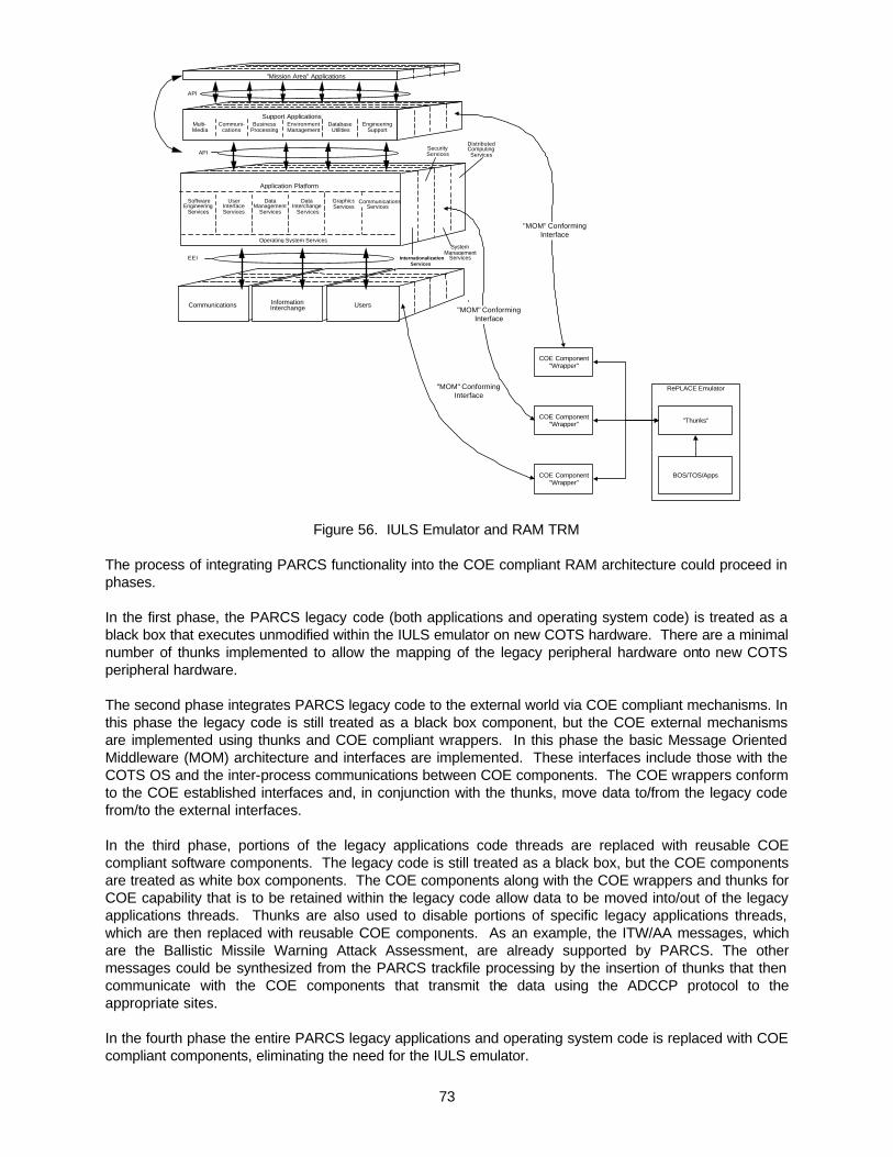
73
EEI
Support ApplicationsMulti-Media
InformationInterchangeCommunications Users
BusinessProcessing
Communi-cations
EnvironmentManagement
DatabaseUtilities
EngineeringSupport
Application Platform
SoftwareEngineering
Services
UserInterfaceServices
DataManagement
Services
DataInterchange
Services
GraphicsServices
CommunicationsServices
API
"Mission Area" Applications
API
InternationalizationServices
SecurityServices
DistributedComputingServices
SystemManagement
Services
Operating System Services
RePLACE Emulator
BOS/TOS/Apps
"Thunks"
COE Component"Wrapper"
COE Component"Wrapper"
COE Component"Wrapper"
"MOM" ConformingInterface
"MOM" ConformingInterface
"MOM" ConformingInterface
Figure 56. IULS Emulator and RAM TRM The process of integrating PARCS functionality into the COE compliant RAM architecture could proceed in phases. In the first phase, the PARCS legacy code (both applications and operating system code) is treated as a black box that executes unmodified within the IULS emulator on new COTS hardware. There are a minimal number of thunks implemented to allow the mapping of the legacy peripheral hardware onto new COTS peripheral hardware. The second phase integrates PARCS legacy code to the external world via COE compliant mechanisms. In this phase the legacy code is still treated as a black box component, but the COE external mechanisms are implemented using thunks and COE compliant wrappers. In this phase the basic Message Oriented Middleware (MOM) architecture and interfaces are implemented. These interfaces include those with the COTS OS and the inter-process communications between COE components. The COE wrappers conform to the COE established interfaces and, in conjunction with the thunks, move data to/from the legacy code from/to the external interfaces. In the third phase, portions of the legacy applications code threads are replaced with reusable COE compliant software components. The legacy code is still treated as a black box, but the COE components are treated as white box components. The COE components along with the COE wrappers and thunks for COE capability that is to be retained within the legacy code allow data to be moved into/out of the legacy applications threads. Thunks are also used to disable portions of specific legacy applications threads, which are then replaced with reusable COE components. As an example, the ITW/AA messages, which are the Ballistic Missile Warning Attack Assessment, are already supported by PARCS. The other messages could be synthesized from the PARCS trackfile processing by the insertion of thunks that then communicate with the COE components that transmit the data using the ADCCP protocol to the appropriate sites. In the fourth phase the entire PARCS legacy applications and operating system code is replaced with COE compliant components, eliminating the need for the IULS emulator.

74
Integrating PARCS into the broader UEWR architecture requires more detailed analysis. A preliminary analysis of this question is summarized in the following tables. It should be noted however, although emulation offers promise for porting portions of the current object code to a new architecture, it does not address any of the maintainability issues cited in the reference materials. In particular, the absence of a source baseline for PARCS is not addressed, nor are issues associated with maintaining an obsolete CENTRAN source language.
Key System Architecture Features Pros / Cons
Processing Architecture • Symmetrical Multi-Processor architecture allows throughput increase simply by adding additional processors.
• The TOS/BOS operating system architecture requires much manual labor to break application code into runable threads.
SAFEGUARD Processors • Will be insupportable in very near future • Not DII COE compliant • Not viable UEWR option
Radar Controller / Signal Processor • Dated equipment which will be become insupportable in near future
• Difficult to add NMD processing requirements • Not DII COE compliant
Operator Interface • Dated and insupportable technology • Not DII COE compliant
External Communication Devices • Dated and insupportable equipment Operating System • Proprietary OS supported only on SAFEGUARD
Processors • Not DII COE compliant • Not viable option
Table 13. PARCS System Architecture Analysis

75
Key Software Issues Pros / Cons
Support of UEWR and NMD Requirements
• Provides the Early Warning and Space Surveillance missions as is
• Operator Interface software modifications required
• Radar scheduling, commanding, and returns processing modifications required
• Tracking algorithm modifications may be required
• Object typing and discrimination modifications required
Tasking Architecture • Basic tasking architecture is non-standard and requires much manual preparation.
• Use of overlays must be removed
• Porting to alternative OS will cause much breakage in applications and in preparation process.
• Modifications to top level architecture will be required to support NMD and migration to MOM or CORBA based architecture
Implementation in SNX/CENTRAN • No support of SNX/CENTRAN on modern platforms
• Reengineering to another language (e.g., Ada) will require significant resources
OS Dependencies • Port to alternative OS will cause significant breakage
TTY and Card Reader based operator interfaces
• Not DII COE compliant
• Use of DII COE compliant approach will result in high breakage in operator interface software area
Management of disk based data via OS file services
• Use of OS file services reduces interoperability and flexibility
• Use of OS file services requires development of application specific access code
• Use of OS file services for persistent data provides ability to tailor for performance considerations
• Port to alternative OS will cause breakage in applications.
Table 14. PARCS Software Architecture Analysis
6.2.4 PARCS and National Missile Defense In February 2000, a preliminary presentation regarding the IULS PARCS domain analysis was provided to personnel at the PARCS site. The briefing indicated that it did not appear that an incremental upgrade of PARCS was cost effective and that it could not be initiated under IEIST funding. It was suggested that the possibility of including PARCS in the National Missile Defense (NMD) infrastructure should be examined. In response to this suggestion, a visit to Washington DC, to the Boeing NMD project was executed. It was learned that PARCS is not presently included in the NMD architecture because inclusion of PARCS offers no enhancement in NMD system effectiveness, which is measured by the percentage of incoming missile threats, which are killed by NMD. In terms of early detection of in-coming missile threats, PARCS offers no coverage which is not provided by another asset and PARCS detection of an incoming threat is not sufficiently timely to enable successful engagement. However, it is possible to build a case for integrating PARCS into the NMD architecture. Although PARCS offers no increase in system effectiveness, it does offer an interim improvement in the Kill Assessment capability, until the time the Final SBIRS High satellite

76
is deployed (earliest 2008). Kill Assessment is not an NMD system requirement but is highly desired by the NMD customer. 6.3 PARCS and IEIST During March 2000 the status of the PARCS domain analysis was briefed to USSPACECOM personnel at Peterson AFB. They were also told that incremental upgrade of PARCS would not be executed under IEIST funding. At that time it was hoped that PARCS could be included as a node in the Joint Battlespace Infosphere in one or more of the IEIST scenarios. During the aforementioned visit to the Boeing National Missile Defense project, the potential for an IEIST NMD scenario was explored. The viability of including the Perimeter Attack Characterization Radar System in the NMD architecture was also discussed. The results of the meeting were not favorable in terms of identifying a candidate scenario. The primary objectives regarding the IEIST scenario are: 1) integration of legacy embedded systems into the Joint Battlespace Infosphere (JBI), 2) leveraging of IULS and related AFRL technologies and 3) building upon the foundation scenario and architecture developed for WSOA/QuoTE. Based upon the information exchange at the meeting, we did not believe that we could develop a credible NMD scenario, which satisfies the primary IEIST objectives. NMD execution timelines are limited to very short duration (on the orders of seconds) and extremely high system reliability because the NMD scenarios focus on weapons to destroy in-coming ballistic missiles themselves, and not the launchers (which clearly do fit the IEIST CONOPS). The consensus was that there is little or no potential fit between NMD and IEIST. 6.4 PARCS Summary This IULS PARCS study was initiated to examine the feasibility of utilizing the IULS toolset to incrementally upgrade PARCS to alleviate a hardware obsolescence problem. The analysis indicates that this could be reasonably accomplished. However, part of the IULS upgrade process entails evaluation of the overall cost effectiveness of the upgrade. The results here are not promising. Because of the obsolete and unmaintainable nature of the PARCS software, incremental upgrade cannot be recommended. An alternate approach of re-architecting PARCS under the RAMP program was examined. This approach is viable and might be enhanced using IULS tools to assist in the process. We believe that emulation could be applied to develop an interim product, but in the long-run maintainability issues need to be addressed. Also, as we have indicated the selective use of code translator technology should be explored if a PARCS upgrade program is initiated. It is believed that an IULS Technology Demonstration could be constructed along these lines. It is suggested that an effort be undertaken to identify funding for this approach. A starting point for generating the need could be the NMD interim Kill Assessment capability afforded by PARCS. Certainly, continuation of its current space tracking function is an additional need for PARCS.

77
7 IULS CV-22 Transition The objective of this on-going technology development is to demonstrate, extend, and transition IULS toolset technology to the Air Force special operations variant of the V-22, denoted the CV-22. The program began in July 2000. The current CV-22 system of the Special Operations Command (SOCOM) includes an Advanced AYK-14 mission computer. Although not yet in full- scale production, the CV-22 faces problems including hardware obsolescence and limited growth potential. The CV-22 program roadmap (following figure) identifies a major upgrade, Block 20, which will commence EMD in FY2002.
CV-22 Block UpgradeStrategy
(post CV-22 PMR draft 1)
FY00 FY01 FY02 FY03 FY04 FY05 FY06 FY07 FY08 FY09 FY10 FY11
Block 0 EMD
FeaturesMultimode RadarSIRFCWing FuelAVSS
4Block 0
6Block 10
9Block 10
9Block 20
9Block 20
9Block 30
4Block 30Flt Director ImprovementsCSELLink 16FMU ImprovementsMATT Text MessagesCARPOffboard NBC Director
CAAP vice MMRTurreted Gun (V22)GCAWS (V22)GANS/GATM = Cockpit Voice Rec - VADR TCAS
Full-up DIRCM Jam TurretsEGI vice LWINS/MAGR (V22)Addt’l SATCOM
Cockpit Hoist ControlTrp Cmdr SA ConnectionsDIRCM Processor & AAR-54AVR-2A Laser DetSecond Fwd Firing DispDual Digital MapRelocate ALE-47 head/busEW Bus Controller BackupExtendable Refueling Probe (V22)
Block 10 EMD
FE Display PagesAirframe Provisions for: DIRCM 2nd Fwd Firing Disp
Block 20 EMD
Block 30 EMD
lot 5
lot 6
lot 7
lot 8
lot 9
lot 10
lot 11
OPR: CV-22 SPO staffMaj K. Cunningham
DSN 757-8087Rev C: 19 Nov 99
NOTE: Block 10 as expected in EMD contract (about to be let)Block 20 as planned/discussed in CV-22 PMR Nov 99Block 30 is notional - for Evolutionary Acq planning
Figure 57. CV-22 Program Roadmap One of the key components of Block 20 is the Common Avionics Architecture for Penetration (CAAP), starting in the in the 2001 time frame. CAAP has three main objectives: 1) Reduce enemy ability to detect incoming SOF penetration aircraft; 2) Fuse off-board and on-board data for enhanced situational awareness; and 3) Create a common processing architecture for all future SOF aircraft. Features of the CAAP program are illustrated in the following figure. The CV-22 will require significant additional processing resources to accommodate requirements for new and expanded capabilities for terrain following and situation awareness as identified for CAAP. The CV-22 program is supporting a detailed trade study to identify potential technologies for meeting these processor requirements.

78
3
Improved Improved TF / TA TF / TA
NavigationNavigation
Enhanced Enhanced SituationalSituationalAwarenessAwareness
(ESA)(ESA)
Obstacle Obstacle Avoidance/Avoidance/
Cable Cable WarningWarning(OA/CW)(OA/CW)
GlobalGlobalAccess,Access,
Navigation,&Navigation,&SafetySafety
(GANS)(GANS)
Intel Broadcast ReceiverIntel Broadcast Receiver
OSAOSAProcessorProcessor
ColorColorDisplaysDisplays
GPS
DigitalDigital Map Map
EW BusEW Bus
SMMUSMMU
USSOCOMUSSOCOMFY00-05 POMFY00-05 POM
ESAESASoftwareSoftware
OA/CWOA/CWSoftwareSoftware
GANSGANSSoftwareSoftware
TF/TATF/TASoftwareSoftware
Display Display GeneratorsGenerators
HSDBHSDB
O/S, DBM,O/S, DBM,DTED,DTED,
A/C DataA/C Data
BLOSTD/GBLOSTD/G Special ReceiverSpecial Receiver
DTDDTD
OA/CWOA/CWSensor(s)Sensor(s)
GANSGANSData LinksData Links& Radios& Radios
Figure 58. CAAP Program Elements In this effort, IULS technology for automatic generation of wrapper software is being applied to investigate migration of the CV-22 to a Commercial Off-The-Shelf processor (PowerPC) and incorporation of prototype CAAP functionality. This effort includes development of a lab-quality COTS Replacement Box (CRB) that incorporates significant and applicable components of CV-22 mission processing functionality, and prototype CAAP functions for terrain following. The following figure depicts the CV-22 processor architecture and CRB migration. Prototype CAAP processing to be "wrapped" into the mission processor was selected from candidates including blended radar processing, data fusion, and enhanced situation awareness. The Quiet Knight ATD, a precursor to CAAP, has demonstrated the feasibility and effectiveness of CAAP technology, and provides a source of prototype CAAP software.
PowerPC Processor(s)
COTS Replacement Box (CRB)
Real-Time Object Request Broker
Prototype CAAP Functionality• Terrain Following• Blended Radar Processing• Situation Awareness• Fusion
LegacyJASS OFP
Bold StrokeInfrastructure
MIPS Processor
Advanced Mission Computer
RCM Operating System Program(ROSP)
Ada Run-Time System (AdaRTS)
LegacyJASS OFP
LegacyExecutive
IULS
Wrappers
Figure 59. CV-22 Processor Architecture and CRB Migration The effort supports key avionics upgrade trade studies being considered by the CV-22 for transition to an open system architecture by providing performance benchmarks and risk reduction. The effort includes both re-host activities to transition to the COTS processor, and incorporation of prototype CAAP functionality. The IULS toolset developed under the IULS program is being applied to support automatic generation of wrapper software for the new functionality.

79
This IULS TD program has significant potential carry-forward technology for the CV-22 program. First, it will provide essential data supporting the CV-22 open system trade study by wrapping and rehosting JASS software to an open system-based CRB. Second, it will verify performance, generate benchmark data, and establish CRB growth potential to support CV-22 requirements by conducting CV-22 integration tests to validate migration to a COTS processor. Finally, it will provide advanced risk reduction for SOCOM / CV-22 and demonstrate transitionability of the IULS technology by "wrapping" prototype CAAP functionality. The CV-22 IULS effort represents a variation of the "rehost" wrapper approach. This technique leverages extensive software development activity by the V-22 program in generation of the JASS Ada 83 baseline, and facilitates potential re-use of Quiet Knight and other potential CAAP functionality. The rehost effort provides a migration of the OFP from the legacy advanced AYK/14 processor to an open Bold Stroke configuration. In the CV-22 case, the legacy advanced AYK/14 processor does not have the growth potential to meet the demanding processing requirements for CAAP. Wrappers are being constructed around the re-hosted software, and around the prototype CAAP software. The following figure shows the legacy system and the wrapped demonstration system.
VMEbus
AMC
CommonOFP Library
IULSFramework
Library Single Card Processor
JASSApplications
CAAPComponents /
Wrapper
DisplayDriver
DisplayServices
COTS Mission Processor
ReuseComponents
WrapperComponents
RCM
RehostWrapper
I/O Services
EXECWrapper
Ethernet
Green Hills MULTIWind River TornadoCV-22 Environment
PCWorkstation
JASS AvionicsApplications
RCM OperatingSystem Program
Ada Run TimeEnvironment
Upgrade/PIMWrapper
CAAP ComponentLibraryWrapper
Components
Upgrade/PIMWrapper
Figure 60. Legacy and Demonstration System Architecture The Boeing Company is pursuing a very similar 'rehost' approach on the F-15E production program. In that case, F-15E flight software is being rehosted from the legacy Ada 83 software operating on the VHSIC Central Computer to the Bold Stroke environment using Ada 95. This approach resulted from a comprehensive trade study, which considered many different options for F-15E integration within Bold Stroke environment. The following figure shows the options that were considered in the study. Option 4 - Utilize Infrastructure Services - was selected for implementation. It provides rehosted Ada code on the PowerPC and utilizes low-level Bold Stroke infrastructure services. Considerations that led to the selection were: 1) Options 4 and 5 will minimize the cost of future SW enhancements and maintenance, by making it easier to distribute the code and multi-thread the application; 2) Options 3, 4 and 5 will minimize the cost of future H/W upgrades by insulating the user application from the underlying HW and operating system; and 3) Options 3,4, 5 provide a path for easier migration to a long term object oriented solution. The IULS CV-22 program is able to directly utilize Ada bindings to the Bold Stroke infrastructure that were developed as

80
a direct result of this option. In addition, F-15E lessons learned on development of the new executive, use of the infrastructure, and support for global I/O databases are being applied to the VC-22 TD program.
1 2 3 4 5Rehost to
Bare Machine
Utilize vxWorks and CSS
Utilize Low-Level Infrastructure
Services
Utilize Infrastructure
Services
Utilize Avionics Interface Layer
Approach Rehost Ada Rehost Ada Rehost Ada Rehost Ada Rehost AdaUse Avionics Level I/F AI
Exec Routine New Exec New Exec New Exec Use High Level Infrastructure Exec
High Infra
Use of BS Infrastructure Services
Low Level Infra Low Level Infra Low Level Infra
Use of BS Core Services
CSS CSS CSS CSS
Operating System vxWorks vxWorks vxWorks vxWorksCPU Dy4 FFW Dy4 FFW Dy4 FFW Dy4 FFW Dy4 FFWLogical Device Interfaces
HW HW HW HW HW
Option
Figure 61. F-15E Options for Rehost 7.1 Foundation Programs This element of the Incremental Upgrade of Legacy Systems demonstration program is based upon the adaptation of the V-22 Osprey’s JASS Avionics Operational Flight Program (OFP). JASS is the embedded avionics OFP that was designed and targeted for a custom built Advanced Mission Computer (AMC) written entirely in the Ada-83 programming language. Components of the embedded operating system components, provided by the computer manufacturer were written in Ada as well. The development of the AMC and the operating system components were funded by the V-22 program and the LAMPS Update program by Loral and Computing Devices International (currently known as General Dynamics Information Systems). The JASS software application was designed as a single Configuration Item (CI) integrating 13 functional areas. These areas include Aircraft Subsystems, Blade Fold /Wing Stow, Central Integrated Checkout, Communications and Identification, Controls and Displays, Electronic Warfare, Executive, Flight Director and Guidance, Mission Management, Multifunction Remote Terminal Input Output, Navigation, and Tactical Sensors. The runtime system is based upon the Ada run-time system that is included with the Rational Software VADS Ada Cross-Development System. The runtime component provides a multitask, priority based, periodic operating system. Inter-task communication is achieved by the use of mailboxes, allowing data and messages to be passed and executed at the appropriate task priority. This element of the IULS demonstration integrates portions of the JASS application software with CORBA-compliant ORB software and a run-time system that is commercially available. The integration of these software components then provides the foundation for the inclusion of additional avionics functionality that can be integrated via an open system interface. The demonstration will also address the issues that involve the use of multi-language implementations where the host application and the ORB interface will utilize Ada and C++. Additional multi-language considerations will be determined during the assessment of additional avionics functionality. An early task in the transition effort was a trade to identify the JASS Functional Areas with the highest relevance to CAAP. These are the best candidates for rehost to the Bold Stroke Architecture under the IULS Transition effort. The following figure shows the initial component selection. It will be confirmed through additional system analysis before the demonstration content is finalized.

81
Bold Stroke Infrastructure MIL-STD-1553B
Aircraft Subsystems
Blade Fold/Wing Stow
Central IntegratedCheckout
Communicationsand Identification
Controls and Displays
ElectronicWarfare Executive
Flight Director and Guidance
Mission Management
Multifunction Remote Terminal Input Output
Navigation
Tactical Sensors
Recording
JASSJASS
Figure 62. Tech Demo Components Selected for CAAP Relevancy (Preliminary)
The following figure illustrates the architectural organization of the software that will result from the CV-22 TD program.
Hardware (CPU, Memory, I/O)Board Support Package
Run Time Operating SystemInfrastructure Services
CAAPJASS
(Ada 83)
Figure 63. CV-22 Demonstration Software Architecture 7.2 IULS CV-22 Transition Benefits The CV-22 IULS TD program provides extensive transition benefits to the CV-22 program. First, the IULS TD program is demonstrating through execution of system level tests that the CRB incorporating the rehosted / wrapped JASS software can successfully complete “red-lined” CV-22 test procedures. This establishes the fidelity of the wrapping, and will provide a path that can affordably migrate the JASS OFP from the legacy advanced AYK/14 to a much more powerful COTS Open System CPU. Moreover, this effort demonstrates the use of software wrappers to enable incorporation of prototype CAAP functionality. This will further demonstrate the growth potential of the COTS system and enable generation of system benchmarks including spare capacity. The TD program represents a major risk reduction for the CV-22 program as it looks to develop its future end-state software and hardware architecture in preparation for planned Block upgrades. The benefits of the IULS CV-22 Transition are captured in the following figure.

82
LegacyProcessor
Sync
In
Out
Put Get
...11001100011101010101010101010100101110100100110100010101001010...
Legacy OFP(Ada 83)
...110011000111010101010101010101001011101001001101000101010010...
UpgradeProcessor
PowerPCAdv. AYK-14 (MIPS)
Tech Demo Outputs• Proof of Concept for CV-22
Open System ArchitectureCandidate
• Demonstrated GrowthPotential for CAAPFunction
• Upgrade to CV-22 withCandidate CAAP S/W usingIULS Toolset to Auto GenWrapper
• Wrapping legacy S/Wenables incrementalupgrades and incrementalre-qualification
IULS AutoWrapper
Legacy System Issues• Limited / No Expandabilityin current CPU to meetSOCOM needs
• Proprietary processor andsystem bus
PowerPC Processor
COTS Replacement Box (CRB)
Real-Time Object Request Broker
Candidate CAAP Functionality• Terrain Following• Blended Radar Processing• Situation Awareness• Fusion
CandidateCAAPS/W
Migrate toAda 95
LegacyJASS OFP
Bold StrokeInfrastructure
Figure 64. CV-22 Demonstration Outputs

83
8 Other Wrapper Applications and Upgrade Technology This section will describe the application of software wrappers to other embedded systems and application domains, and discuss related software technology that can be applied to the upgrade problem. 8.1 Other IULS Applications 8.1.1 Open Systems Architecture Wrappers The IULS approach is currently being applied to reuse embedded software for the AFRL Weapon System Open Architecture (WSOA) CRAD Project. The objective of the project is to prototype middleware and application software to enable a weapon platform such an F-15 and a command and control C2) platform such as an AWACS to exchange images and to collaboratively replan a mission efficiently via a Link 16 network. The project’s demonstration fighter node is F-15E1, the same vehicle and processor/OFP used for the IULS OWS demonstration described in Section 5. The OFP did not have a JTIDS processing function to support the project. A mature JTIDS function was available from the F-15 production OFP that supported the operation of a Class II terminal, the Link-16 interface and cockpit display formats drivers. As in the F-15 OWS case, the reusable JTIDS software did not match the host language (Ada83 vs. C++) or architecture (hierarchical vs. OO). IULS methodology was used to perform a brief FODA that indicated that a wrapper was feasible and the best way to provide the F-15 OFP with the JTIDS functionality. The architecture of the OFP with wrapped JTIDS software is very similar to the OWS wrapper architecture illustrated in Figure 17. The major differences are that the JTIDS components are larger and more self-contained (the major data interfaces are internal PIMs between components), and they are all executed only at a 20Hz rate. The software is at the “Design Wrapper” process step at the time of this writing. In 1998, the use of IULS methodology was included in a Boeing (McDonnell Douglas) proposal to NASA to upgrade the Space Shuttle’s avionics system. The Shuttle’s quad-redundant central computers have obsolete processors and the OFPs are written in a unique, costly to maintain language called HAL. The three approaches summarized in Section 3.1 were considered and variations were proposed. The computers perform both mission and flight critical (inner-loop flight control) processing so the IULS tools would have to be extended and their operations formally qualified for this domain by Honeywell. This task is reasonable since Honeywell has another specialized tool in this family for flight control software, but it would be out-of-scope for the IULS project. Due to programmatic issues including cost/schedule constraints, NASA has not contracted an upgrade, and a new round of studies is currently in progress. 8.1.2 Wrappers For Scientific Computing There is a large body of software written over the past 30 year that supports the engineering and scientific community and is now becoming obsolete in terms of source and object language, host system dependencies, and compatibility with new software systems including distributed processing. It is typically written in early versions of FORTRAN running on dedicated mainframes or “minis” for one specialist user and is rarely well documented. The IULS project had a technical exchange with JPL staff members regarding the upgrading and reuse of their optics analysis utility library. Their organization maintains a large library of similar applications and is interesting in modernizing the software systems and making them more user-friendly. They had already proposed and manually implemented wrappers for some applications, and they were intrigued by the automated analysis and design capabilities of IULS. During the technical exchange, it was obvious that the small interface size and uniqueness of each application would make the cost of analysis, modeling, evaluation, and interface library-building with the IULS toolset unjustifiable. Their work can serve as a model for upgrading this domain of software. 8.1.3 Wrappers For Business and Information System Applications There is a huge body of software written over the same period for the business and financial community employing a wide variety of architectures, languages, APIs, databases, and user interfaces. The most common language is COBOL, and most common user access is dumb terminals and point of sale/entry devices. The vision of most of the business world is “e-Business” that is being implemented in distributed,

84
heterogeneous processing and “Web-like” user interfaces. Upgrading and “Web-a-fying these systems is currently a massive undertaking that uses wrappers/adapters to some extent. The IULS team had several technical exchanges with the Boeing corporate data processing support group that is responsible for this transformation within Boeing. We concluded that the IULS toolset was too specialized (embedded, real-time) for this software domain although Honeywell conceptualized and demonstrated how it could be extended for business applications, languages (including C++ and Java), and interfaces. Major software and hardware manufactures (Oracle, Microsoft, Sun, IBM, etc.) now provide this upgrade service with a wrapper approach as one of their techniques. There is a growing body of academic research in classifying software architectures (notably at Carnegie Mellon University), and then identifying techniques for resolving software component “packaging” mismatches with wrappers, bridges, mediators, etc. [see Reference 3 in Section 10.1, Bibliography]. Wrappers are being implemented commercially for legacy data sources and database systems (as in IBM’s Garlic project, [18]), and for systems interaction (brokers, agents, and protocols by Sun). OO wrappers for DOD information systems were the subject of an Institute for Defense Analysis study for the Defense Information Systems Agency in 1996. This work was described in the report Legacy System Wrapping for DOD Information Systems Modernization [4]. Several migration strategies and guidelines are described including SQL-to-Ada bindings for wrapping a database management system. A wrapper generator, “Rapper”, was developed for a CIA database management system during a study by MITRE Corporation that arrived at some of the same lessons learned as IULS [14]. 8.2 Wrappers and Software Reuse Since the IULS Project began in 1997, the software engineering discipline of reusable software has grown and matured greatly. While the major thrust is designing for reuse and “product-line software development”, much of the methodology can also be applied to software upgrades: domain analysis, architectural patterns and modeling, and re-engineering or refactoring of existing software for reuse. The Boeing Phantom Works OSA group has been a leader in reuse technology in the real-time embedded object oriented software domain [23]. There are many technical papers and books, conferences, and tutorials that describe software reuse technology in many software domains such as those by Ivar Jacobsen [8]. 8.3 Other Software Upgrade Approaches Both DoD and the commercial world have developed upgrade techniques that are similar to IULS wrapper approaches and/or share some of the same principles such as model-based re-engineering. The first design activity of the “Rehost approach” typically consists of translation and/or recompilation of the legacy software so it can be executed (re-used) on the upgraded processor inside a wrapper. Under the Embedded Information System Re-Engineering (EISR) project for AFRL, Lockheed Martin is developing an automation-assisted JOVIAL-to-C re-engineering capability that permits transformation of both the software’s source language and architecture [12]. Automated JOVIAL-to-Ada translation was used successfully by Boeing to rehost the C-17’s Mission Computer OFP to the COTS CIP processors for the upgrade described in Section 6.6.3 [17]. And the list of target processors supported by the USAF’s JOVIAL toolset has grown to include COTS processors [http://www.jovial.hill.af.mil]. A variation of the “Hybrid approach” employing a split processor chassis is being used in several upgrades. Generally a new chassis is designed with sections for legacy modules and their backplane, and new COTS-based modules and their backplane. A backplane bridge is designed to link the two sections containing adapter software; additional wrappers are developed for the upgraded applications on the new processor modules. For example, the new AV-8B “OSCAR” Weapon Processor contains COTS processors on a VME backplane running re-engineered OFPs, and a section of legacy backplane housing reused weapon interface modules that have no COTS equivalent (and would be too expensive to re-engineer).

85
A variation of software-based legacy “Emulator approach” that was successfully demonstrated on IULS and other programs, is the firmware or hardware-based emulator. For example, CPU Technologies has produced a 1750 emulator “system-on-a-chip” that is being used to upgrade the F-16’s radar processor [http://www.cputech.com]. The problem of inserting new and upgraded software into real-time software architectures in a safe and reliable manner is addressed by the Simplex Architecture from the Software Engineering Institute [22]. It provides for the dynamic alteration of active systems, as well as fault tolerance and support for heterogeneous languages and processors in a real-time system. It has been demonstrated a number of times and is well-documented [http://www.sei.cmu.edu/simplex]. Simplex is a key element of the Incremental Software Evolution for Real-Time Systems (INSERT) R&D program that Lockheed Martin is conducting for AFRL. It has produced a “COTS-based solution for building high-assurance applications”. The “replacement” applications are run on top of an INSERT middleware layer that insulates (wraps) them from the underlying RTOS and processor hardware, and provides virtual memory partitioning and communication via asynchronous messaging. The INSERT system has been demonstrated in a rehost of F-16 AFTI JOVIAL weapon delivery software from a 1750 processor to a Pentium processor [1]. 8.4 Upgrade Tools and Modeling Two technologies that IULS employs have expanded and matured since IULS was proposed: Model-based software development and a related area, auto-code generation. HTC’s DOME and WrapidH are the practical foundation for the IULS methodology. Since IULS began, the Unified Modeling Language (UML) has become the standard for object oriented software development, and has successfully been implemented in software development systems such as Rational’s Rose [http://www.rational.com]. The DOME notation toolset includes a subset of UML but WrapidH was not revised to include it. UML is a viable alternative to modeling existing as well as new application software and wrappers, but the model could not be the source for to the IULS Honeywell analysis and code generation capabilities. However, automatic generation of code from UML models in several HOLs is the goal of integrated tool vendors such as Rational [15]. Generic patterns are now commonly used for characterizing and designing software. The publication of the Gamma patterns book [6] formally introduced a basic family. Among the most useful are the Façade, Adapter, and Proxy structural patterns, and the Mediator behavioral pattern. More specialized interface patterns are especially valuable to describe wrapper design such as the Wrapper Façade [19], whose intent is to “encapsulate low-level, stand-alone functions with OO class interfaces”. Another example of a pattern application to wrapper design is the interface between OO software and entity or relational databases (RDBs) that are common in business systems. They can be built with generic data interface components through a data object generalization pattern [10] that is a generalization of the data conversion wrapper components designed for the F-15 OWS wrapper. Several code analysis tools were examined early in the IULS project for their usefulness in characterizing legacy software during domain analysis that may require reverse engineering if the product is not well documented. The McCabe toolset [http://www.mccabe.com], and in particular, the “Battlemap” was found to be a valuable way to visualize existing Ada and C software. An evaluation copy of the Xinotech toolset [http://www.xinotech.com] was acquired and applied to some of the legacy F-15 code during the FODA phase. Since the F-15 OFP was well known and documented, the tool’s output did not add much value. However since that time, both toolsets have been enhanced and bundled with other tools. Xinotech is promoted as a robust reengineering system and is being used successfully on the ESIR project that was previously described. Another visualization/reverse-engineering toolset family that software reuse designers have found useful is Understand for FORTRAN, Understand for Ada, and Understand for C from Scientific Toolworks [http://scitools.com]. This type of analysis tool should be a part of the upgrade SEE along with DoME and WrapidH. There are a number of ongoing projects in industry and academia in the areas of tools and methodology for software analysis, design, test, and documentation that could be applied to the upgrade process. For

86
example, DARPA/ITO under the Evolutionary Design of Complex Software (EDCS) program sponsored the Capability Packaging for Avionics (CPAS) project at Northrop Grumman Corporation. CPAS integrated EDCS technologies in three areas: Software understanding through visualization tools; incremental analysis/test and certification tools; and architecture-driven design and composition tools. CPAS has been applied to the B-2 avionics system software in preparation for incremental enhancement as well as ongoing maintenance [http://www.northrop.com/cpas].

87
9 IULS Lessons Learned and Conclusion This section summarizes some lessons learned during the project regarding software upgrades using wrapper technology and the IULS methodology. 9.1 IULS Process We found that following the wrapping process described in Section 3 does result in a reasonably well- designed OFP for our F-15 applications, and several steps yielded lessons learned or are especially noteworthy. The most essential and time-consuming pre-design step was the characterization of the legacy software. The older the software, the less likely that it has complete and/or accurate documentation including comprehensive test cases. It is vital that a domain expert with tribal knowledge of the design and operation be involved in the documentation of the data interfaces. Each interface parameter must be analyzed and classified in minute detail as illustrated for the F-15 project in Section 4.3 and the data mapping table in Appendix A. This table was in use until the final code corrections were made prior to system integration. This task can be done more efficiently with the code parsing tools and re-engineering tools mentioned earlier. The wrapper control flow and top-level architecture were relatively easy to design because the wrapped parts were modular and had straightforward execution dependencies. The wrapper designer has some flexibility in this area, especially if unexecuted code and unused parameters can be left in the reused legacy code after they are understood/documented. Training on the IULS toolset and the RePLACE systems is required, even for experienced software designers. Some experience with model-based software development is very helpful. Those doing the detailed wrapper design and integration/test activities must be skilled in the wrapper language(s), and have at least a working knowledge of the legacy/rehosted software language as well. TRW’s RePLACE system is relatively independent of the IULS toolset. Integrating the two was out of scope for the current project. The domain analysis and characterization process steps must be completed no matter which “back end” wrapper design process is employed. Although the wrapper approach has been validated for upgrades in many software domains, the IULS toolset is currently targeted to the embedded mission processing domain. The characterization steps are widely applicable, but the model library and code generation steps are currently applicable to embedded Ada and C code. The IULS toolset is most valuable for wrappers with larger data interfaces yet with similar patterns and constructs. This allows the exploitation of the component library, class structures and autocoding. 9.2 Upgrade Programmatics Once the technical aspects of an upgrade have been addressed, an even greater challenge is addressing the programmatic issues starting with the decision to preserve, maintain and upgrade or rather redesign the system. This challenge is described by Schneidewind for the IEEE [20], Ragland for the USAF [16], and in the IULS Final Technical Report, Task 1. Total re-engineering has many advantages if it is affordable, including an opportunity to take control and document (e.g., “re-baseline”) the design using improved methodology and tools after long periods of “maintenance”. There are much-improved software cost estimating tools available such as Price S [http://www.pricesystems.com] to characterize partial redesign (with some reuse), designing a replacement from current requirements, or total re-engineering from fundamental requirements. The cost of the wrapper itself is characterized as “automated software development”. A valuable reference with regard to re-engineering is the Software Reengineering Assessment Handbook from the DOD Joint Group on Systems Engineering [JLC-HDBK-SRAH]. It is a fact-of-life in most software domains that near-term funding is much easier to acquire than long term for a number of reasons. Maintenance and minor upgrades are generally less costly and produce
88
immediate, identifiable returns whereas larger, longer-term re-engineering efforts are more costly and promise less quantifiable life-cycle savings. The IULS approach to upgrades falls somewhere in between. It is obvious from the IULS upgrade projects that the best opportunity to re-engineer for upgrade and reuse is in conjunction with major functional or hardware upgrades. This is also the best context for evaluating the use of an emulator wrapper. Life cycle costs must be analyzed and documented, including the increasing cost of maintaining legacy requirements, documentation, and support software [21]. The open systems upgrade planning process can be aided by lessons-learned from activities such as AVPLEX which is a “Model for Avionics Upgrade Planning and Execution” [13]. One of the unstated goals of the project was to generalize the experiences and lessons-learned from the case studies and demonstrations into an tool’s algorithm or set of rules to guide a program in choosing between re-engineering and wrapped upgrades, and among the wrapper approaches. One of the lessons-learned, however, was that this determination is typically complex and unique for every program because of the factors addressed in the preceding sections. Whilst a "template" based approach to determining upgrade strategies is a good first step to weigh options, our experience has shown that each program must systematically do the technical analysis (including the pre-design phases of the wrapper process), the life-cycle analysis (including cost models), and the programmatic factor analysis to determine their best course of action. Tech transition is achievable (and has been demonstrated on IULS) but requires proving the technology performs, and performs in ways that were not necessarily intended at design. Tech transition to a risk averse production program requires constant attention, and close collaboration and risk mitigation strategies. The tech transition path for an organization that does not have an existing relationship to the production program is difficult at best and at times nearly impossible. Even when the technology has proven itself, production programs may remain skeptical and need to be coaxed into accepting potential risky technology. Finally, transition success can ultimately depend on factors totally independent of the technology value. The demonstrated value of the wrapper toolset was less relevant to the F-15 program after their roadmap changed to embrace an Ada rehost vice a C++ re-engineering. 9.3 Summary The IULS project has produced a near turn-key system to facilitate incremental improvements to fielded weapon system avionics using software wrappers. A Software User Manual is available that contains wrapper guidelines and architectures, and describes the use of the WrapidH toolset. The F-15 OWS, C-17 CCU, and CV-22 demonstrations described in the report are real-world examples of the application of the IULS process.. The WrapidH toolset and current Wrapper Library are available from Boeing Phantom Works [http://PhantomWorks.boeing.com] for installation and use on a PC/Windows Workstation. The Domain Modeling Environment is also available from the project or can be downloaded directly (without cost) from Honeywell [http://www.htc.honeywell.com/dome]. It is an extensible collection of integrated model editing, meta-modeling, and analysis tools (including UML) supporting a model-based development approach to system/software engineering in many software domains. The specialized RePLACETM toolset for developing emulation-based embedded software wrappers was developed for AFRL by TRW-Dayton and is currently being employed on a number of embedded software upgrade projects as well as the C-17 CCU upgrade. It is available from TRW [http://www.trw.com]. The wrapper approach to incremental avionics upgrades and enhancements is intuitively appealing, and a number of projects that have heard about IULS have, at least, included the concept in their upgrade trade space. It is a valuable resource in the growing effort to deal with aging aerospace vehicles and their avionics. And it is coincident with the development of upgrade and reuse technology in many other software domains.

89
10 Notes 10.1 Bibliography The following materials are additional sources of information that were referenced by [number] and/or found useful by the IULS project. 1. Calloni, Ben, et.al., INSERT: A COTS-Based Solution For Building High-Assurance Applications,
paper presented to the 18th Digital Avionics Systems Conference, 24-29 October 1999. 2. Cook, David and Leslie Dupaix, A Gentle Introduction to Software Engineering, USAF Software
Technology Support Center, 1999. 3. DeLine, Robert, A Catalog of Techniques for Resolving Packaging Mismatch, ACM, January 1999. 4. Diskin, David, Legacy System Wrapping for DOD Information System Modernization, Institute for
Defense Analysis for the Defense Information System Agency, Joint Interoperability & Engineering Organization, 1996.
5. Floyd, Jon and Phil Mastrolia, The DOD Generic Fighter: F-22’s Historical Foundation; paper presented to the Seventh Annual Software Technology Conference, 14 April 1995.
6. Gamma, Eric, et.al., Design Patterns: Elements of Reusable Object-Oriented Software, Addison-Wesley, 1995.
7. Garnett, Lucy, Wrapping Objects, Journal of Object Oriented Programming, January 1997. 8. Jacobsen, Ivar, et.al., Software Reuse; Architecture, Process and Organization for Business
Success, Addison Wesley, 1997. 9. Kang, Kyo C., et al; Feature-Oriented Domain Analysis (FODA) Feasibility Study (CMU/SEI-90-TR-
21, ESD-90-TR-222); Software Engineering Institute, Carnegie Mellon University, November 1990. 10. Kwon Il-Myoung, et.al., Building Generic Data Interface Components through a Data Object
Generalization Pattern, Journal of Object-Oriented Programming (JOOP), October 2000. 11. Laufmann, S. C., Toward Agent-Based Software Engineering for Information-dependent Enterprise
Applications, IEE Proceedings – Software Engineering, Vol. 144, No. 1, February 1997. 12. Littlejohn, Kenneth and Michael DelPrincipe, Embedded Information Systems Re-Engineering, paper
presented to the 18th Digital Avionics Systems Conference, 24-29 October 1999. 13. Logan, Lt Col Glen and Charles Hurst, AVPLEX, A Model for Avionics Upgrade Planning and
Execution, paper presented to the 18th Digital Avionics Systems Conference, 24-29 October 1999. 14. Mattox, David with Len Seligman and Ken Smith, Rapper: A Wrapper Generator With Linguistic
Knowledge, ACM, February 1999. 15. Mellor, Stephen, Automatic Code Generation from UML Models, one of series of articles in C++
Report, June 1999. 16. Ragland, Bryce and Michael Olsem; Maintain Legacy Software or Reengineer?, article in CrossTalk
Magazine, The Journal of Defense Software Engineering, April 1996. 17. Rhine, Keith, The C-17 Core Integrated Processor (CIP) Project, paper presented to the 16th Digital
Avionics Systems Conference, 5 November 1997. 18. Salzberg, Don’t Scrap It, Wrap It! A Wrapper Architecture For Legacy Data Sources, ACM SIGMOD
Digital Review, 1999. 19. Schmidt, Douglas, Wrapper Façade: A Structural Pattern for Encapsulated Functions within Classes,
C++ Report, February 1999. 20. Schneidewind, Norman and Christof Ebert, Preserve or Redesign Legacy Systems, IEEE Software
Journal, July/August 1998. 21. Schneidewind, Norman, Now To Evaluate Legacy System Maintenance, IEEE Software Journal,
July/August 1998. 22. Sha, Liu, Ragunathan Rajkumar, and Michael Gagliardi: Evolving Dependable Real-Time Systems;
Software Engineering Institute, Carnegie Mellon University, 1996. 23. Sharp, David, Containing and Facilitating Change Via Object Oriented Tailoring Techniques, paper
presented to the 12th Software Technology Conference, 30 April – 5 May 2000.

90
Acronyms and Abbreviations ADCP Advanced Display Core Processor (F-15) ADL Architecture Description Language AFRL Air Force Research Lab AIDS Aircraft Integrated Data System AISF Avionics Integration Support Facility (C-17) AL Assembly language API Application Program Interface APM, A/PDMC Avionics/Propulsion Data Management Computer (C-17) ARINC Aeronautical Radio, Inc. AVMUX Avionics multiplex bus A/A Air-to-Air A/G Air-to-Ground BIF Built-In Function BIT Built-In Test BTOS Basic Operating System CAAP Common Avionics Architecture for Penetration CAU Cautions CCU Communication Control Unit (C-17) CFT Conformal fuel tanks (F-15) CIP Core Integrated Processor (C-17) CLC Central Logic and Control (PARCS) CLD Critical Local Data CNAV Common Navigation COE Common Operating Environment CNI Communication, Navigation, Identification COFP Common OFP (Boeing IRAD project) CONOPS Concept of Operations CORBA Common Object Request Broker Architecture COSA Communication Open System Architecture COSSI Commercial Operations and Support Savings Initiative, Dual Use Applications Program COTS Commercial Off-the-Shelf CPM Computer Processor Module CPS Cabin, Pressure Sensor (Controller) CPU Central Processing Unit CRAD Contracted Research and Development CRB COTS Replacement Box (C-17) CRT Cathode Ray Tube CSC Computer Software Component C/D Control and Display DMA Direct Memory Access DoME Domain Modeling Environment DPM Data Processor Module DSSSL Document Style Semantics and Specification Language DTE Desktop Test Environment EEC Engine, Electronic Control EWS Early Warning System EXEC Executive FCC Flight Control Computer FODA Feature-Oriented Domain Analysis FTR Flight Test Recorder GATM Global Air Traffic Management GDIS General Dynamics Information Systems (formerly Control Data, “CDInt”),
[http://www.gd-is.com] GP General Purpose (Processor) GSE Ground Support Equipment HOL High Order Language
91
HTC Honeywell Technology Center HS Hamilton Standard HSDB High Speed Data Bus HUD Head-Up Display H/W Hardware IBIT Initiated BIT IDEF Integrated Computer-Aided Manufacturing Definition Language IEIST Insertion of Embedded Infosphere Support Technologies IOM Input/Output Module (F-15) IOP Input/Output Processor IRMS Integrated Radio Management Systems (C-17) ISA Instruction Set Architecture I/O Input/Output IULS Incremental Upgrade of Legacy Systems JASS Joint Vertical Experimental Avionics System Software LCD Liquid Crystal Display LM Lockheed Martin MDA McDonnell Douglas Aerospace (now Boeing) MC Mission Computer MCK/MCD Mission Control Keyboard/Display MLP Memory Loader Program MMU Memory Management Unit MPDP Multi-Purpose Display Processor (F-15) MSIP Multi-Stage Improvement Program (F-15) MTA Boeing Military Transport Aircraft MUX Multiplex Bus NAV Navigation NMD National Missile Defense NVRAM Non-Volatile RAM OFP Operational Flight Program OO Object-Oriented ORB Object Request Broker OSCAR Open Systems Core Avionics Requirements OTS Off-the-Shelf OWS Overload Warning System (F-15) O/S Operating System PARCS Perimeter Attack Radar Characterization System PIM Process Interface Message (F-15) PML Performance Model Library PROM Programmable Read-Only Memory RAM Random Access Memory RAMP Radar Architecture Migration Program RCF Radio Control Function (C-17) RePLACE Reconfigurable Processor for Legacy Avionics Code Execution (TRW) RFP Request for Proposal RISC Reduced Instruction Set Architecture RTOS Real-Time Operating System RTS Run-Time System or Software SEE Software Engineering Environment SEI Software Engineering Institute SLOC Software Lines of Code SMP Symmetrical Multi-Processing SOF Special Operations Forces SRAM Semiconductor (volatile) RAM SUM Software User Manual SUROM Start-Up Read Only Memory S/W Software TCAS Traffic Alert and Collision Avoidance Systems

92
TD Technology Demonstration TOS Tactical Operating Systems UML Unified Modeling Language UFC Up Front Control VCC VHSIC Central Computer (F-15) VHDL VHSIC Hardware Description Language VME Versa Module Eurocard WACS Warning and Cautions System (C-17) WSOA Weapon System Open Architecture WSSTS Weapon System Software Technology Support

93
Glossary Architecture - The high level packaging of functions and data to implement an application. Architecture modeling - Mapping the domain model to a software architecture to solve domain
problems. Context - The environment in which the software exists. Context Analysis - Establishing the scope and environment of a domain, and identifying the external
conditions and interfaces, which cause variations. Domain - A class of software that provides services for solving a similar set of problems (applications
or capabilities). Domain Modeling - Identifying the common features/problems addressed by the software domain using
models. A domain model defines the functions, objects, data, and their relationships in the domain. Feature - A prominent, distinctive characteristic or behavior. Feature Oriented Domain Analysis - Aggregation and generalization to capture the commonality in
software applications using the process of context analysis, domain modeling, and architecture modeling.
Patterns - Design patterns provide guidelines for applying the reference architecture and components to different domains and contexts.
Reference architecture - Provides examples, which are used as a guideline or template for developing the actual wrapper architecture for an upgrade.
Repository of components - A collection of components including primitive wrapper parts and execution environments that can be picked up by the tool to construct an upgrade wrapper.

94
Appendix A. Overload Warning System / Common OFP Mapping Table
F-15 OWS PIM F-15 COFP D_ADC_20HZ_INPUT_PIM MACH_NUMBER : Mach;
type Mach is new Real range -20.0 .. 20.0;
A5ADP.h(57): const BQualityDouble& GetMach(); Ex. theA5ADP_Ptr->GetMach() Returns reference to BqualityDouble – GetValue() returns mach/double/dimensionless, IsValid() returns bool.
D_ADC_20HZ_INPUT_PIM LOCAL_ANGLE_OF_ATTACK : Cockpit_Units; type Cockpit_Units is new Real;
A5ADP.h(56): const BAnglePiOver2& GetLocalAngleOfAttack(); Ex. theA5ADP_Ptr_-> GetLocalAngleOfAttack().GetAngle() Returns reference to BAnglePiOver2 – BAglePiOver2 derived from class Bangles – GetAngle() returns Local Angle Of Attack/double/radians limited to –Pi/2 to Pi/2.
D_ADC_20HZ_INPUT_PIM LOCAL_ANGLE_OF_ATTACK_ VALID : Boolean;
A5ADP.h(56): const BAnglePiOver2& GetLocalAngleOfAttack(); Ex. theA5ADP_Ptr_-> GetLocalAngleOfAttack().IsValid() Returns reference to BAnglePiOver2 – BAglePiOver2 derived from class Bangles -- IsValid() returns bool
D_ADC_20HZ_INPUT_PIM BARO_CORRECTED_ PRESSURE_ALTITUDE : Feet; type Feet is new Real;
A5ADP.h(123): const virtual BqualityDouble& GetBaroCorrectedPressureAltitude(); Ex. theA5ADP_Ptr_-> GetBaroCorrectedPressureAltitude() Returns reference to BqualityDouble – GetValue() returns Baro Corrected Pressure Altitude/double/ft, IsValid() returns bool.
D_ADC_20HZ_INPUT_PIM TRUE_ANGLE_OF_ATTACK : Elevation_Type; subtype Elevation_Type is Radians range -Pi / 2.0 .. Pi / 2.0; type Radians is new Real range -3.0 * Pi .. 3.0 * Pi;
A5ADP.h(64): const BAnglePiOver2& GetTrueAngleOfAttack(); Ex. theA5ADP_Ptr_-> GetTrueAngleOfAttack() Returns reference to BAnglePiOver2 – BAglePiOver2 derived from class Bangles – GetAngle() returns True Angle Of Attack/double/radians limited to –Pi/2 to Pi/2, IsValid() returns bool.
D_ADC_20HZ_INPUT_PIM PRESSURE_RATIO : Unitless; type Unitless is new Real;
A5ADP.h(61): const BQualityDouble& GetPressureRatio(); Ex. theA5ADP_Ptr_-> GetPressureRatio() Returns reference to BqualityDouble – GetValue() returns pressure ratio/double/dimensionless, IsValid() returns bool.
D_AFCS_20HZ_INPUT_PIM MODE_DISCRETE_WORD
.SPIN_RECOVERY_DISPLAY : Boolean;
A5AFCS.h(98): inline bool GetSpinRecoveryDisplay(); Ex. theA5AFCS_Ptr_-> GetSpinRecoveryDisplay() Returns bool which can be used to populate the appropriate bit in D_AFCS_20HZ_INPUT_PIM.PIM.MODE_DISCRETE_WORD. SPIN.DISCOVERY.DISPLAY
D_AFCS_20HZ_INPUT_PIM MODE_DISCRETE_WORD .LANDING_GEAR_HANDLE_ IS_UP : Boolean;
A5AFCS.h(76): inline bool GetLandingGearHandleIsUp(); Ex. theA5AFCS_Ptr_-> GetLandingGearHandleIsUp() Returns bool which can be used to populate the appropriate bit in D_AFCS_20HZ_INPUT_PIM.PIM. MODE_DISCRETE_WORD. LANDING_GEAR_HANDLE_IS_UP
D_AFCS_20HZ_INPUT_PIM MODE_DISCRETE_WORD .YAW_RATE_TONE_ PRIORITY : Boolean;
A5AFCS.h(110): inline bool GetYawRateTonePriority(); Ex. theA5AFCS_Ptr_-> GetYawRateTonePriority(); Returns bool which can be used to populate the appropriate bit in D_AFCS_20HZ_INPUT_PIM.PIM. MODE_DISCRETE_WORD. YAW_RATE_TONE_PRIORITY
D_AFCS_20HZ_INPUT_PIM R_H_STABILATOR_RAM_ POSITION : Degrees; type Degrees is new Real range -360.0 .. 360.0;
A5AFCS.h(92): const BQualityDouble& GetRH_StabRamPosition(); Ex. theA5AFCS_Ptr_-> GetRH_StabRamPosition(); Returns reference to BqualityDouble – GetValue() returns RH Stabilator RAM Position/double/radians.
D_AFCS_20HZ_INPUT_PIM RIGHT_STAB_MAIN_RAM_ POS_IS_VALID D_OWS_20_HZ_LIB.perform_validity_checks.ada Validity_Word.Right_Stab_Main_RAM_Pos_Is_Valid : Boolean;
A5AFCS.h(93): A5AFCS.h(92): inline bool GetRightStabMainRamPosIsValid(); Ex. theA5AFCS_Ptr_-> GetRightStabMainRamPosIsValid(); Returns bool to be used for RIGHT_STAB_MAIN_RAM_POS_IS_VALID.

95
F-15 OWS PIM F-15 COFP D_AFCS_20HZ_INPUT_PIM L_H_STABILATOR_RAM_
POSITION : Degrees; type Degrees is new Real range -360.0 .. 360.0;
A5AFCS.h(83): const BQualityDouble& GetLH_StabRamPosition(); Ex. theA5AFCS_Ptr_-> GetLH_StabRamPosition(); Returns reference to BqualityDouble – GetValue() returns LH Stabilator RAM Position/double/radians.
D_AFCS_20HZ_INPUT_PIM LEFT_STAB_MAIN_RAM_ POS_IS_VALID D_OWS_20_HZ_LIB.perform_validity_checks.ada Validity_Word.Left_Stab_Main_RAM_Pos_Is_Valid : Boolean;
A5AFCS.h(82): A5AFCS.h(92): inline bool GetRightStabMainRamPosIsValid(); Ex. theA5AFCS_Ptr_-> GetLeftStabMainRamPosIsValid(); Returns bool to be used for LEFT_STAB_MAIN_RAM_POS_IS_VALID.
D_AFCS_20HZ_INPUT_PIM ROLL_RATE : Radians_Per_Sec; type Radians_Per_Sec is new Real;
A5AFCS.h(94): const BQualityDouble& GetRollRate(); Ex. theA5AFCS_Ptr_-> GetRollRate(); Returns reference to BqualityDouble – GetValue() returns Roll Rate/double/radians/sec.
D_AFCS_20HZ_INPUT_PIM YAW_RATE : Radians_Per_Sec; type Radians_Per_Sec is new Real;
A5AFCS.h(108): const BQualityDouble& GetYawRate(); Ex. theA5AFCS_Ptr_-> GetYawRate(); Returns reference to BqualityDouble – GetValue() returns Yaw Rate/double/radians/sec.
D_AFCS_20HZ_INPUT_PIM VALIDITY_WORD.YAW_ RATE_IS_VALID : Boolean;
A5AFCS.h(109): bool GetYawRateIsValid(); Ex. theA5AFCS_Ptr_-> GetYawRateIsValid(); Returns bool to be used directly in D_AFCS_20HZ_INPUT_PIM. VALIDITY_WORD.YAW_RATE_IS_VALID
D_AFCS_20HZ_INPUT_PIM VALIDITY_WORD.ROLL_ RATE_IS_VALID : Boolean;
A5AFCS.h(95): bool GetRollRateIsValid(); Ex. theA5AFCS_Ptr_-> GetRollRateIsValid(); Returns bool to be used directly in D_AFCS_20HZ_INPUT_PIM. PIM.VALIDITY_WORD.ROLL_RATE_IS_VALID
D_AFCS_20HZ_INPUT_PIM LATERAL_STICK_FORCE : Pounds range -20.0 .. 20.0; type Pounds is new Real;
A5AFCS.h(79): const BQualityDouble& GetLateralStickForce(); Ex. theA5AFCS_Ptr_-> GetLateralStickForce(); Returns reference to BqualityDouble -- GetValue() returns lateral stick force/double/lbs
D_AFCS_20HZ_INPUT_PIM LATERAL_STICK_FORCE_ IS_VALID : Boolean;
A5AFCS.h(80): bool GetLateralStickForceIsValid(); Ex. theA5AFCS_Ptr_-> GetLateralStickForceIsValid(); Returns bool to be used directly in D_AFCS_20HZ_INPUT_PIM.PIM. LATERAL_STICK_FORCE_IS_VALID
D_AIU_20HZ_INPUT_PIM NAV_POD_PRESENT :
Boolean; TGT_POD_PRESENT : Boolean;
A5AIU.h(427): const AIU_PodStatusType& GetAIU2_PodStatus(); Ex. theA5AIU_Ptr_-> GetAIU2_PodStatus(); Returns reference to PodStatusType which is a structure defined in A5AIU2_Types.h. PodStatusType-> NAV_podPresent is bool which can be used to populate D_AIU_20HZ_INPUT_PIM. PIM.NAV_POD_PRESENT and PodStatusType-> TGT_podPresent is bool which can be used to populate D_AIU_20HZ_INPUT_PIM. PIM.TGT_POD_PRESENT
D_GEN_20HZ_UNPACK_PIM SAFED_OFF_WEIGHT_OFF_
WHEELS : Boolean; A5WeightOffWheels.h(106): inline bool GetWeightOffWheelsSafedOff(); Ex. theA5WOW_LD_Ptr_-> GetWeightOffWheelsSafedOff(); Returns bool to be used directly in D_GEN_20HZ_UNPACK_PIM. PIM.SAFED_OFF_WEIGHT_OFF_WHEELS
D_INS_20HZ_INPUT_PIM NORMAL_ACCELERATION : Feet_Per_Sec_Squared; type Feet_Per_Sec_Squared is new Real;
A5INS.h(88): const BQualityDouble& GetNormalAcceleration() Ex. theA5INS_Ptr_-> GetNormalAcceleration() Returns reference to BqualityDouble – GetValue() returns Normal Acceleration/double/ft/sec2.
D_INS_20HZ_INPUT_PIM ALIGN_STATUS .GYROCOMPASS_ALIGN : Boolean;
A5INS.h(67): const INS_AlignStatusType& GetAlignQuality(); Ex. theA5INS_Ptr_-> GetAlignQuality(); struct AlignStatusType. gyroCompassAlign is bool to be used for ALIGN_STATUS.GYROCOMPASS_ALIGN

96
F-15 OWS PIM F-15 COFP D_INS_20HZ_INPUT_PIM ALIGN_STATUS.STORED_
HEADING_ALIGN : Boolean; A5INS.h(67): const INS_AlignStatusType& GetAlignQuality(); Ex. theA5INS_Ptr_-> GetAlignQuality(); struct AlignStatusType. storedHeadingAlign is bool to be used for ALIGN_STATUS.STORED_HEADING_ALIGN
D_INS_20HZ_INPUT_PIM Inu_Status.POSITION_AND_ VELOCITY_VALID : Boolean;
A5INS.h(123): bool GetPositionAndVelocityValid(); Ex. theA5INS_Ptr_-> GetPositionAndVelocityValid();
D_INS_20HZ_INPUT_PIM Inu_Status.ATTITUDE_VALID : Boolean;
A5INS.h(71): bool GetAttitudeValid(); Ex. theA5INS_Ptr_-> GetAttitudeValid();
D_INS_20HZ_INPUT_PIM Inu_Status.BARO_INERTIAL_ALTITUDE_VALID
A5INS.h(73): bool GetBaroInertialAltitudeValid(); Ex. theA5INS_Ptr_-> GetBaroInertialAltitudeValid();
D_PACS_20HZ_INPUT_PIM NUC_TRNG_SELECTED :
Boolean; A5UPACS.h(56): const A5UPACS_NucDataStructType& GetA5UPACS_NucData(); Ex. theA5UPACS_Ptr_-> GetA5UPACS_NucData(); Returns reference to A5UPACS_NucDataStructType. NucTrainingSelected is bool which can be used directly for D_PACS_20HZ_INPUT_PIM.PIM. NUC_TRNG_SELECTED.

97
Appendix B. Overload Warning System Parameter Stubbing Table
F-15 OWS PIM F-15 COFP D_GEN_10HZ_UNPACK_PIM BRU_STATION_WEIGHT :
D_Ows_Types.Sta_2_8_5_Array_Type; type Sta_2_8_5_Array_Type is array (Sta_2_8_5_L_R_Type range Sta_2 .. Sta_5) of U_Basic_Data_Types.Pounds; type Sta_2_8_5_L_R_Type is (Sta_2, Sta_8, Sta_5, Lcft, Rcft); type Pounds is new Real;
Not available in demo configuration – Use PACS training Capability If (A5UPACS_Station.stations[STA_X] .merPresent) Stub to BRU_STATION_WEIGHT(STA-X) = 0 lbs, else BRU_STATION_WEIGHT(STA-X) = 524.0 lbs for X=2,5,8
D_GEN_10HZ_UNPACK_PIM CFT_STATUS_FLAG : Cft_Type; type Cft_Type is (None, Cft_4, Cft_3);
Not available in demo configuration – Stub to CFT_STATUS_FLAG = CFT_4.
D_GEN_10HZ_UNPACK_PIM AG_WEAPON_COUNT : D_Ows_Types.Ag_Weapon_Count_Array_Type; type Ag_Weapon_Count_Array_Type is array (Sta_2_8_5_L_R_Type) of U_Number_Types.Integer_Short; type Sta_2_8_5_L_R_Type is (Sta_2, Sta_8, Sta_5, Lcft, Rcft); type Integer_Short is range -32768 .. 32767;
Not available in demo configuration – Use PACS training Capability Stub to AG_WEAPON_COUNT(STA_X) = A5UPACS_Stations.stations[STA_X] .wpnCount for X=2,5,8
D_GEN_10HZ_UNPACK_PIM LAUNCHER_WEIGHT : D_Ows_Types.Sta_2_8_Array_Type; type Sta_2_8_Array_Type is array (Sta_2_8_5_L_R_Type range Sta_2 .. Sta_8) of U_Basic_Data_Types.Pounds; type Sta_2_8_5_L_R_Type is (Sta_2, Sta_8, Sta_5, Lcft, Rcft); type Pounds is new Real;
Not available in demo configuration – Stub to LAUNCHER_WEIGHT(STA_2) = LAUNCHER_WEIGHT(STA_8) = 0 lbs. Note LAUNCHER_WEIGHT(STA_5) is not defined.
D_GEN_10HZ_UNPACK_PIM PYLON_WEIGHT : D_Ows_Types.Sta_2_8_5_Array_Type; Type Sta_2_8_5_Array_Type is array (Sta_2_8_5_L_R_Type range Sta_2 .. Sta_5) of U_Basic_Data_Types.Pounds; Type Sta_2_8_5_L_R_Type is (Sta_2, Sta_8, Sta_5, Lcft, Rcft); Type Pounds is new Real;
Not available in demo configuration – Use PACS training Capability If (theA5UPACS_ptr->GetPylonPresentSta2()) Stub to PYLON_WEIGHT(STA_2) = 500.0; Else PYLON_WEIGHT(STA_2) =0.0; if (theA5UPACS_ptr->GetPylonPresentSta5()) Stub to PYLON_WEIGHT(STA_5) = 300.0; Else PYLON_WEIGHT(STA_5) =0.0; if (theA5UPACS_ptr->GetPylonPresentSta8()) Stub to PYLON_WEIGHT(STA_8) = 500.0; Else PYLON_WEIGHT(STA_8) =0.0;

98
F-15 OWS PIM F-15 COFP D_GEN_10HZ_UNPACK_PIM AG_STATION_ID_CODE :
D_Ows_Types.Ag_Station_Id_Code_Array_Type; type Ag_Station_Id_Code_Array_Type is array (Sta_2_8_5_L_R_Type) of U_Pacs_Types.Ag_Store_Type; Type Sta_2_8_5_L_R_Type is (Sta_2, Sta_8, Sta_5, Lcft, Rcft); type Ag_Store_Type is (None, Mk_82, Mk_82Se, Mc_1, Mk_84, Mk_82Ar, Mk_84Ar, Bdu_33, Cbu_52, Cbu_58, Cbu_71, Cbu_87, Cbu_89, Cbu_97, Spare_14, Spare_15, Suu_20, Suu_20M, Suu_20N, Mk_20, Agm_65A, Agm_65B, Agm_65D, Agm_65G, Gbu_15S, Gbu_10A, Gbu_10M, Gbu_12B, Gbu_12C, Gbu_15L, Tgbu_15, Gbu_24, Axq_14, Unknown, Mxu_648, Idlp, Fuel, Spare_37, Alq_119, Alq_131, Blu_107, Gbu_10B, Spare_42, Spare_43, Gbu_24A, Gbu_28, Agm_130A, Agm_130C, Tgm_65A, Tgm_65B, Tgm_65D, Tgm_65G, Spare_52, Spare_53, Spare_54, Spare_55, Spare_56, Spare_57, Spare_58, Spare_59, Spare_60, Spare_61, Spare_62, Spare_63, Spare_64, Spare_65, Spare_66, Spare_67, Spare_68, Spare_69, Spare_70, Spare_71, Spare_72, Spare_73, Spare_74, Spare_75, Spare_76, Spare_77, Spare_78, Spare_79, Spare_80, Spare_81, Spare_82, Spare_83, Spare_84, Spare_85, Spare_86, Spare_87, Spare_88, Spare_89, Spare_90, Spare_91, Spare_92, Spare_93, Spare_94, Spare_95, Spare_96, Spare_97, Spare_98, B61_0, B61_10, B61_2, B61_3, B61_4, B61_5);
Not available in demo configuration – Use PACS training Capability Stub to : AG_STATION_ID_CODE(STA_X) = A5UPACS_Stations.stations[STA_X] .storeLoaded for X=2,5,8
D_GEN_10HZ_UNPACK_PIM AA_STA_2A_MISSILE_WEIGHT_FLAG : U_Basic_Data_Types.Pounds; type Pounds is new Real;
Not available in demo configuration – Stub to: 0 lbs
D_GEN_10HZ_UNPACK_PIM AA_STA_2B_MISSILE_WEIGHT_FLAG : U_Basic_Data_Types.Pounds; type Pounds is new Real;
Not available in demo configuration – Stub to: 0 lbs
D_GEN_10HZ_UNPACK_PIM AA_STA_8A_MISSILE_WEIGHT_FLAG : U_Basic_Data_Types.Pounds; type Pounds is new Real;
Not available in demo configuration – Stub to: 0 lbs
D_GEN_10HZ_UNPACK_PIM AA_STA_8B_MISSILE_WEIGHT_FLAG : U_Basic_Data_Types.Pounds; type Pounds is new Real;
Not available in demo configuration – Stub to: 0 lbs
D_GEN_10HZ_UNPACK_PIM AA_STA_3_MISSILE_WEIGHT_FLAG : U_Basic_Data_Types.Pounds; type Pounds is new Real;
Not available in demo configuration – Stub to: 0 lbs
D_GEN_10HZ_UNPACK_PIM AA_STA_4_MISSILE_WEIGHT_FLAG : U_Basic_Data_Types.Pounds; type Pounds is new Real;
Not available in demo configuration – Stub to: 0 lbs
D_GEN_10HZ_UNPACK_PIM AA_STA_6_MISSILE_WEIGHT_FLAG : U_Basic_Data_Types.Pounds; type Pounds is new Real;
Not available in demo configuration – Stub to: 0 lbs
D_GEN_10HZ_UNPACK_PIM AA_STA_7_MISSILE_WEIGHT_FLAG : U_Basic_Data_Types.Pounds; type Pounds is new Real;
Not available in demo configuration – Stub to: 0 lbs
D_GEN_10HZ_UNPACK_PIM TANK_PRESENT : D_Ows_Types. Tank_Present_Array_Type; type Tank_Present_Array_Type is array (Sta_2_8_5_L_R_Type range Sta_2 .. Sta_5) of Boolean; type Sta_2_8_5_L_R_Type is (Sta_2, Sta_8, Sta_5, Lcft, Rcft);
Not available in demo configuration – Stub to TANK_PRESENT(STA_2) = TANK_PRESENT(STA_8) = TANK_PRESENT(STA_5) = False.

99
F-15 OWS PIM F-15 COFP D_GEN_10HZ_UNPACK_PIM RIGHT_CFT_AG_WPN_IDENT_CODE :
U_Pacs_Types.Ag_Store_Type; type Ag_Store_Type is (None, Mk_82, Mk_82Se, Mc_1, Mk_84, Mk_82Ar, Mk_84Ar, Bdu_33, Cbu_52, Cbu_58, Cbu_71, Cbu_87, Cbu_89, Cbu_9, Spare_14, Spare_15, Suu_20, Suu_20M, Suu_20N, Mk_20, Agm_65A, Agm_65B, Agm_65D, Agm_65G, Gbu_15S, Gbu_10A, Gbu_10M, Gbu_12B, Gbu_12C, Gbu_15L, Tgbu_15, Gbu_24, Axq_14, Unknown, Mxu_648, Idlp, Fuel, Spare_37, Alq_119, Alq_131, Blu_107, Gbu_10B, Spare_42, Spare_43, Gbu_24A, Gbu_28, Agm_130A, Agm_130C, Tgm_65A, Tgm_65B, Tgm_65D, Tgm_65G, Spare_52, Spare_53, Spare_54, Spare_55, Spare_56, Spare_57, Spare_58, Spare_59, Spare_60, Spare_61, Spare_62, Spare_63, Spare_64, Spare_65, Spare_66, Spare_67, Spare_68, Spare_69, Spare_70, Spare_71, Spare_72, Spare_73, Spare_74, Spare_75, Spare_76, Spare_77, Spare_78, Spare_79, Spare_80, Spare_81, Spare_82, Spare_83, Spare_84, Spare_85, Spare_86, Spare_87, Spare_88, Spare_89, Spare_90, Spare_91, Spare_92, Spare_93, Spare_94, Spare_95, Spare_96, Spare_97, Spare_98, B61_0, B61_10, B61_2, B61_3, B61_4, B61_5);
Not available in demo configuration – Stub to RIGHT_CFT_AG_WPN_IDENT_CODE = NONE.
D_GEN_10HZ_UNPACK_PIM LEFT_CFT_AG_WPN_IDENT_CODE : U_Pacs_Types.Ag_Store_Type; type Ag_Store_Type is (None, Mk_82, Mk_82Se, Mc_1, Mk_84, Mk_82Ar, Mk_84Ar, Bdu_33, Cbu_52, Cbu_58, Cbu_71, Cbu_87, Cbu_89, Cbu_97, Spare_14, Spare_15, Suu_20, Suu_20M, Suu_20N, Mk_20, Agm_65A, Agm_65B, Agm_65D, Agm_65G, Gbu_15S, Gbu_10A, Gbu_10M, Gbu_12B, Gbu_12C, Gbu_15L, Tgbu_15, Gbu_24, Axq_14, Unknown, Mxu_648, Idlp, Fuel, Spare_37, Alq_119, Alq_131, Blu_107, Gbu_10B, Spare_42, Spare_43, Gbu_24A, Gbu_28, Agm_130A, Agm_130C, Tgm_65A, Tgm_65B, Tgm_65D, Tgm_65G, Spare_52, Spare_53, Spare_54, Spare_55, Spare_56, Spare_57, Spare_58, Spare_59, Spare_60, Spare_61, Spare_62, Spare_63, Spare_64, Spare_65, Spare_66, Spare_67, Spare_68, Spare_69, Spare_70, Spare_71, Spare_72, Spare_73, Spare_74, Spare_75, Spare_76, Spare_77, Spare_78, Spare_79, Spare_80, Spare_81, Spare_82, Spare_83, Spare_84, Spare_85, Spare_86, Spare_87, Spare_88, Spare_89, Spare_90, Spare_91, Spare_92, Spare_93, Spare_94, Spare_95, Spare_96, Spare_97, Spare_98, B61_0, B61_10, B61_2, B61_3, B61_4, B61_5);
Not available in demo configuration – Stub to LEFT_CFT_AG_WPN_IDENT_CODE = NONE.
D_GEN_10HZ_UNPACK_PIM RIGHT_CFT_AG_WPN_COUNT_FLAG : U_Common_Types.Three_Bits; subtype Three_Bits is Integer_Short range 0 .. 7; type Integer_Short is range -32768 .. 32767;
Not available in demo configuration – Stub to RIGHT_CFT_AG_WPN_COUNT_FLAG = 0
D_GEN_10HZ_UNPACK_PIM LEFT_CFT_AG_WPN_COUNT_FLAG : U_Common_Types.Three_Bits; subtype Three_Bits is Integer_Short range 0 .. 7; type Integer_Short is range -32768 .. 32767;
Not available in demo configuration – Stub to LEFT_CFT_AG_WPN_COUNT_FLAG = 0

100
F-15 OWS PIM F-15 COFP D_GEN_20HZ_UNPACK_PIM PACS_COMBAT_MODE_MISSILE_PRESENT :
Pacs_Combat_Mode_Missile_Present_Type; type Pacs_Combat_Mode_Missile_Present_Type is array (U_Pacs_Types.Weapon_Sta_Type) of Boolean; type Weapon_Sta_Type is (Sta_2A, Sta_2B, Sta_8A, Sta_8B, Sta_3, Sta_4, Sta_6, Sta_7, Sta_2, Sta_8, Sta_5);
Not available in demo configuration – Stub to PACS_COMBAT_MODE_MISSILE_PRESENT(STA_2A) = PACS_COMBAT_MODE_MISSILE_PRESENT(STA_2B) = PACS_COMBAT_MODE_MISSILE_PRESENT(STA_8A) = PACS_COMBAT_MODE_MISSILE_PRESENT(STA_8B) = PACS_COMBAT_MODE_MISSILE_PRESENT(STA_3) = PACS_COMBAT_MODE_MISSILE_PRESENT(STA_4) = PACS_COMBAT_MODE_MISSILE_PRESENT(STA_6) = PACS_COMBAT_MODE_MISSILE_PRESENT(STA_7) = PACS_COMBAT_MODE_MISSILE_PRESENT(STA_2) = PACS_COMBAT_MODE_MISSILE_PRESENT(STA_8) = PACS_COMBAT_MODE_MISSILE_PRESENT(STA_5) = False.
D_GEN_20HZ_UNPACK_PIM ADC_INVALID_FLAG ADC : Boolean; will not be used!!!(ADP)
Not available in COSSI – Stub to ADC_INVALID_FLAG=False
D_GEN_20HZ_UNPACK_PIM SPIKE_CHECK_DATA_IS_SPIKED : Spike_Check_Data_Is_Spiked_Type; type Spike_Check_Data_Is_Spiked_Type is array (Spike_Parameter_Type) of Boolean; type Spike_Parameter_Type is (True_Aoa, Local_Aoa, Mach_Number, Pressure_Ratio, Baro_Corr_Press_Altitude, Pressure_Altitude, Normal_Acceleration);
Not available in COSSI – Stub to SPIKE_CHECK_DATA_IS_SPIKED(TRUE_AOA) = SPIKE_CHECK_DATA_IS_SPIKED(LOCAL_AOA) = SPIKE_CHECK_DATA_IS_SPIKED(MACH_NUMBER) = SPIKE_CHECK_DATA_IS_SPIKED(PRESSURE_RATIO) = SPIKE_CHECK_DATA_IS_SPIKED(BARO_CORR_PRESS_ALTITUDE) = SPIKE_CHECK_DATA_IS_SPIKED(PRESSURE_ALTITUDE) = SPIKE_CHECK_DATA_IS_SPIKED(NORMAL_ACCELERATION) = False
D_HUD_CONTROL_PIM AOA_LIMIT.DISPLAYED_VALUE : Num.Integer_Short
range 20 .. 50; type Integer_Short is range -32768 .. 32767;
Not available in demo configuration – Stub to 50 cockpit units (Note stub is short integer type) to ensure logic to activate tone is not entered (tone capability is not wired in airplane)
D_MPDP_20HZ_INPUT_PIM GRP_ACTIVE : Grp_Active_Array;
type Grp_Active_Array is array (Side_A_B) of Mpdpt.Grp_Active_Type; type Side_A_B is (Side_A, Side_B); type Grp_Active_Type is array (Cmt.Du_Type) of Boolean; for Grp_Active_Type'Size use 8;
Not available in demo configuration – Stub GRP_ACTIVE(SIDE_B)(DU7) to True
D_MPDP_20HZ_INPUT_PIM GRP_ASSIGNED_TO_BUS_B : Grp_Assigned_To_Bus_B_Array; type Grp_Assigned_To_Bus_B_Array is array (Side_A_B) of Mpdpt.Grp_Assigned_To_Bus_B_Type; type Side_A_B is (Side_A, Side_B); type Grp_Assigned_To_Bus_B_Type is array (Cmt.Du_Type) of Boolean; for Grp_Assigned_To_Bus_B_Type'Size use 8;
Not available in demo configuration – Stub GRP_ASIGNED_TO_BUS_B (SIDE_B)(DU7) to True

101
F-15 OWS PIM F-15 COFP D_MPDP_20HZ_INPUT_PIM CAU_NORMAL_ACCELERATION : Bdt.G_Accel;
type G_Accel is new Real range -16.0 .. 16.0; -- Acceleration, gravities
Not available in demo configuration -- Use INS value as default. A5INS.h(88): const BQualityDouble& GetNormalAcceleration() Ex. theA5INS_Ptr_-> GetNormalAcceleration() Returns reference to BqualityDouble – GetValue() returns Normal Acceleration/double/ft/sec2. (Convert from ft/sec2 to g’s for CAU_NORMAL_ACCELERATION) IsValid() returns bool.
D_MPDP_20HZ_INPUT_PIM LEFT_CFT_FUEL_WEIGHT : Bdt.Pounds; type Pounds is new Real;
Not available in demo configuration – Stub to 4524. lbs
D_MPDP_20HZ_INPUT_PIM RIGHT_CFT_FUEL_WEIGHT : Bdt.Pounds; type Pounds is new Real;
Not available in demo configuration – Stub to 4524. lbs
D_MPDP_20HZ_INPUT_PIM TOTAL_FUEL_WEIGHT : Bdt.Pounds; type Pounds is new Real;
Not available in demo configuration – Stub to 13300 lbs If VALUE entered from scratch-pad, TOTAL_FUEL_WEIGHT=VALUE*100 lbs limited 0 to 13300 lbs.
D_MPDP_20HZ_INPUT_PIM GP_ROTATING_BIT_PATTERN : Mpdpt. Gp_Rotating_Bit_Pattern_Type; type Gp_Rotating_Bit_Pattern_Type is (Frame_0, Frame_1, Frame_2, Frame_3);
Not available in demo configuration – Set GP_ROTATING_BIT_PATTERN = FRAME_0, FRAME_1,FRAME_2,FRAME_3 on a rotating basis at 20 Hz.
D_MPDP_20HZ_INPUT_PIM OWS_RESET_SWITCH_DEPRESSED : Boolean; Not available in demo configuration – Stub to False
D_PACS_20HZ_INPUT_PIM PACS_INOPERATIVE_RESET_BIT_FLAG : Boolean; Not available in demo configuration –
Stub to PACS_INOPERATIVE_RESET_BIT_FLAG = False
D_PACS_20HZ_INPUT_PIM UNKNOWN_WPN_WEIGHT_CLASS : Pacst.Unknown_Wpn_Weight_Class_Type; type Unknown_Wpn_Weight_Class_Type is (Ows_Off, Class_1, Class_2, Class_3);
Not available in demo configuration – Options are OWS_OFF, CLASS_1, CLASS_2, CLASS_3. For demo stub to OWS_OFF.
I_PACS_CMBT_TRNG_ BUFFER
MSG_06_WORD_10.NUC_TRNG_LOAD_RC : U_Pacs_Types.Nuc_Training_Store; type Nuc_Training_Store is (None, Spare_1, Suu_20, Spare_2, Bdu_38);
Not available in demo configuration – It is set equal to a NUC_TRNG_LOAD_TYPE which is set equal to an element from NUC_TRAINING_STORE. Options for NUC_TRAINING_STORE are NONE, SPARE_1, SUU_20, SPARE_2 and BDU_38. For demo, stub to NONE.
I_PACS_CMBT_TRNG_ BUFFER
MSG_06_WORD_08.NUC_TRNG_LOAD_LC U_Pacs_Types.Nuc_Training_Store; type Nuc_Training_Store is (None, Spare_1, Suu_20, Spare_2, Bdu_38);
Not available in demo configuration – It is set equal to a NUC_TRNG_LOAD_TYPE which is set equal to an element from NUC_TRAINING_STORE. Options for NUC_TRAINING_STORE are NONE, SPARE_1, SUU_20, SPARE_2 and BDU_38. For demo, stub to NONE.
X_EXECUTIVE_CONTROL FIRST_PASS_FOR_10_HZ : First_Pass_Flag_Type;
type First_Pass_Flag_Type is (Not_First_Pass, Power_Up, Pilot_Reset, Reconfiguration); (Note change of variable name from …10HZ to …10_HZ)
Not available in demo configuration – Options are NOT_FIRST_PASS, POWER_UP, PILOT_RESET and RECONFIGURATION. Set to POWER_UP for first execution of 10HZ and 10HZ WARN, NOT_FIRST_PASS for subsequent executions.

102
F-15 OWS PIM F-15 COFP X_EXECUTIVE_CONTROL H2_PERIPHERAL_DATA_INVALID :
H9_Peripheral_Data_Invalid_Type; type H9_Peripheral_Data_Invalid_Type is array (H9_Peripheral_Type) of Boolean; type H9_Peripheral_Type is (Dbiu, Adc, Ahrs, Spare_3, Spare_4, Spare_5, Pacs, Spare_7, Sdrs, Spare_9, Spare_10, Rwr, Spare_12, Spare_13, -- SPARE_13 is reserved for AHRS problem workaround Si, Ics);
Not available in demo configuration? – Stub to X_EXECUTIVE_CONTROL.H2_DATA.H2_PERIPHERAL_DATA_ INVALID(PACS) = False
X_EXECUTIVE_CONTROL DISP_20_HZ_PERIPHERAL_DATA_INVALID : Disp_Peripheral_Data_Invalid_Type; type Disp_Peripheral_Data_Invalid_Type is array (Disp_Peripheral_Type) of Boolean; type Disp_Peripheral_Type is (Reserved_0, Spare_1, Spare_2, Spare_3, Spare_4, Spare_5, Spare_6, Spare_7, Spare_8, Spare_9, Spare_10, Spare_11, Spare_12, Spare_13, Spare_14, Spare_15, Mpdpa, Mpdpb, Spare_18, Spare_19, Spare_20, Spare_21, Spare_22, Spare_23, Spare_24, Spare_25, Spare_26, Spare_27, Spare_28, Spare_29, Cc_Rt, Reserved_31);
Not available in demo configuration? – Stub to X_EXECUTIVE_CONTROL.A1_DATA.DISP_20_HZ_PERIPHERAL_DATA_ INVALID(D_MPDP_PACKING_PIM.PIM.GPIO)=False X_EXECUTIVE_CONTROL.A1_DATA.DISP_20_HZ_PERIPHERAL_DATA_ INVALID(MPDPB)=False
X_EXECUTIVE_CONTROL DISCRETE_INPUTS : Discrete_Inputs_Type; type Discrete_Inputs_Type is array (Discrete_Inputs_Index) of Boolean; for Discrete_Inputs_Type'Size use 16; type Discrete_Inputs_Index is (Aiu1_Go, Unused_2, E1, Unused_4, Unused_5, Unused_6, Unused_7, Unused_8, Unused_9, Unused_10, Unused_11, Unused_12, Unused_13, Unused_14, Unused_15, Unused_16);
Stub X_EXECUTIVE_CONTROL.PIM.DISCRETE_INPUTS(E1) = TRUE
X_EXECUTIVE_CONTROL AV_PERIPHERAL_DATA_INVALID : Av_Peripheral_Data_Invalid_Type; type Av_Peripheral_Data_Invalid_Type is array (Av_Peripheral_Type) of Boolean; for Av_Peripheral_Data_Invalid_Type'Size use 32; type Av_Peripheral_Type is (Reserved_0, Redu, Spare_2, Spare_3, Gps, Ins, Spare_6, Spare_7, Sfdr, Ledu, Radar, Rwr, Reserved_Mpdp, Spare_13, Spare_14, Ics, Spare_16, Map, Aiu1A, Aiu1B, Aiu2, Nav_Pod, Tgt_Pod, Afcs, Adp, Spare_25, Spare_26, Spare_27, Spare_28, Si, Cc_Rt, Reserved_31);
Not available in demo configuration? --Stub to X_EXECUTIVE_CONTROL.AI_DATA. AV_PERIPHERAL_DATA_INVALID(INS) = False X_EXECUTIVE_CONTROL.AI_DATA. AV_PERIPHERAL_DATA_INVALID(AFCS) = False

103
F-15 OWS PIM F-15 COFP D_DISPLAY_MGMT_PIM FORMAT_LOCATION_INDICATOR_ARRAY(OWS) :
Format_Location_Indicator_Array_Type; type Format_Location_Indicator_Array_Type is array (Cmt.Format_Type) of Cmt.Du_Location_Type; subtype Format_Type is Format_Codes_Type range None .. Srad; type Format_Codes_Type is -- MENU 1 FORMATS (None, -- 0 also HUD Eadi, -- 1 Armt, -- 2 Ehsi, -- 3 Tf_Rdr, -- 4 Tsd, -- 5 Menu_1_Pb_6_Reserved, -- 6 Menu_1_Pb_7_Reserved, -- 7 Menu_1_Pb_8_Spare, -- 8 Menu_1_Pb_9_Spare, -- 9 Vtrs, -- 10 Menu_2, -- 11 Tgt_Ir, -- 12 Tews, -- 13 Ag_Rdr, -- 14 Aa_Rdr, -- 15 Menu_1_Pb_16_Spare, -- 16 Hud_Repeater, -- 17 Eng, -- 18 Event, -- 19 Bit, -- 20 -- MENU 2 FORMATS Wind_Model, -- 21 Ag_Delivery, -- 22 Menu_2_Pb_3_Spare, -- 23 Menu_2_Pb_4_Spare, -- 24 Data_Frame, -- 25 Menu_2_Pb_6_Reserved, -- 26 Menu_2_Pb_7_Reserved, -- 27 Menu_2_Pb_8_Spare, -- 28 Menu_2_Pb_9_Spare, -- 29 Ows, -- 30 Menu_1, -- 31 Menu_2_Pb_12_Spare, -- 32 Menu_2_Pb_13_Spare, -- 33 Menu_2_Pb_14_Spare, -- 34 Menu_2_Pb_15_Spare, -- 35 Vid_8, -- 36 Hud_Prog, -- 37 Vid_5, -- 38 Dtm, -- 39 Vid_2, -- 40 -- FORMATS NOT ON MENU Srad, Spare42, Spare43, Spare44, Spare45, Spare46, Spare47, Spare48, Spare49, Spare50, Spare51, Spare52, Spare53, Spare54, Spare55, Spare56, Spare57, Spare58, Spare59, Spare60, Spare61, Spare62, Spare63); subtype Du_Location_Type is Refresh_Bufr_Location_Type range None .. Du7; type Refresh_Bufr_Location_Type is (None, Du0, Hud, Du2, Du3, Du4, Du5, Du6, Du7, Macro_Subs, Cautions);
Not available in demo configuration – Stub to =NONE

104
F-15 OWS PIM F-15 COFP D_DISPLAY_MGMT_PIM DISPLAY_BUFFER_ARRAY.
PUSHBUTTON_DEPRESSION_NUMBER Display_Buffer_Array : Display_Buffer_Array_Type; type Display_Buffer_Array_Type is array (Cmt.Du_Type) of Display_Buffer_Type; subtype Du_Type is Du_Location_Type range Du0 .. Du7; subtype Du_Location_Type is Refresh_Bufr_Location_Type range None .. Du7; type Refresh_Bufr_Location_Type is (None, Du0, Hud, Du2, Du3, Du4, Du5, Du6, Du7, Macro_Subs, Cautions); Pushbutton_Depression_Number : Mpdpt.Du_Pushbutton_Type; subtype Du_Pushbutton_Type is Du_Switch_Code_Type range None .. Pb_20; type Du_Switch_Code_Type is (None, Pb_1, Pb_2, Pb_3, Pb_4, Pb_5, Pb_6, Pb_7, Pb_8, Pb_9, Pb_10, Pb_11, Pb_12, Pb_13, Pb_14, Pb_15, Pb_16, Pb_17, Pb_18, Pb_19, Pb_20, Spare_21, Spare_22, Spare_23, Bright_Increase, Bright_Decrease, Contrast_Increase, Contrast_Decrease, Spare_28, Spare_29, Spare_30, Initiated_Bit);
Not available in demo configuration. It will not be accessed if FORMAT_LOCATION_INDICATOR_ARRAY(OWS)==NONE. Can be stubbed to =CLR for completeness, but not required.
N_ENGINE_MONITOR_05HZ_PIM
IPE_INSTALLED : Boolean; A5EDU.h(80): XTypes::UInt16 GetTypeOfEngine(); Compare: theLEDU_Ptr->GetTypeOfEngine()==PW229 And theREDU_Ptr->GetTypeOfEngine()==PW229 If both are true, IPE_INSTALLED = True, else False

105
Appendix C. Sample WrapidH C++ Listing
/******************************************** File generated by WrapidH, version 1.1 *********************************************/ #include "D_OWS_10_HZ_C_PIM.h" #include "D_OWS_20_HZ_C_PIM.h" #include "A5ADP.h" Uses the Host’s ADP aircraft state data #include "D_ADC_C_PIM.h" #include "D_AFCS_C_PIM.h" #include "A5AFCS.h" #include "D_MPDP_C_PIM.h" #include "BQualityDouble.h" #include "A5AIU.h" #include "D_AIU_C_PIM.h" #include "A5EDU.h" #include "N_ENGINE_MONITOR_05HZ_C_PIM.h" #include "A5UPACS.h" #include "D_PACS_C_PIM.h" #include "A5WeightOffWheels.h" #include "D_GEN_20HZ_C_PIM.h" #include "A5INS.h" #include "BAnglePiOver2.h" #include "D_INS_C_PIM.h" #include "D_OWS_TYPES.h" #include "U_BASIC_DATA_TYPES.h" #include "INTERFACES.C.h" #include "U_NUMBER_TYPES.h" #include "XTypes.h" #include "Unknown.h" #include "A5AIU2_Types.h" #include "A5ADP_Device.h" #include "A5AFCS_Device.h" #include "A5AIU_Device.h" #include "A5EDU_Device.h" #include "A5UPACS_Device.h" #include "A5WeightOffWheels_Device.h" #include "A5INS_Device.h" #include "OWS_Wrapper.h" Uses the top-level wrapper class OWS_Wrapper { public: OWS_Wrapper(); Boolean GetAOA_THRESHOLD_EXCEEDED(); FIXED_POINT_SHORT_SCALE_17_TYPE GetBIT_AUDIT_TOTAL_AIRCRAFT_WEIGHT(); Boolean GetCAU_FAILURE_DETECTED(); Boolean GetCAU_FAILURE_DETECTED_THIS_PASS(); G_ACCEL GetCAU_NZ_LOAD_FACTOR_INPUT(); Boolean GetCAU_NZ_MONITOR_ON(); CFT_TABLE_TYPE GetCFT_FUEL_WEIGHT(); C_float GetCFT_NZ_ALLOWABLE(); CFT_TABLE_INDEX_TYPE GetCFT_TABLE_INDEX(); CFT_TABLE_TYPE GetCFT_TOTAL_WEIGHT(); WARNING_RATIO_TYPE GetCFT_WARNING_RATIO(); DECIMAL_DEGREES GetDECIMAL_AOA(); INTEGER_SHORT GetDEFAULT_AOA_TONE_LIMIT(); Boolean GetDISPLAY_BLANKS_FOR_AOA(); POUNDS_PER_SQUARE_FOOT GetDYNAMIC_PRESSURE(); FLAG_TYPE_FOR_DTM_WRITE GetEND_OF_EVENT_FOR_DTM_WRITE(); Boolean GetFIRST_CAU_FILTER_PASS(); C_float GetFWD_FUSELAGE_NZ_ALLOWABLE(); C_float GetFWD_FUSELAGE_WARN_RATIO(); Boolean GetGOTO_END_OF_CALC_MASS_ITEMS(); Boolean GetHUD_INVALID_ARMT_DISP(); Boolean GetINFLIGHT_INVALID_ARMT_DISP(); Boolean GetINS_GROUND_ALIGN_COMPLETE(); G_ACCEL GetINS_NZ_LOAD_FACTOR_INPUT(); G_ACCEL GetLAST_PASS_CAU_FILTER_OUTPUT(); G_ACCEL GetLAST_PASS_CAU_NZ(); G_ACCEL GetLAST_PASS_INS_FILTER_OUTPUT(); POUNDS GetLAST_PASS_LATERAL_STICK();

106
G_ACCEL GetLAST_PASS_NORMAL_ACCELERATION(); Boolean GetLATCH_CAU_FAILURE(); WARNING_RATIO_TYPE GetLEFT_TAIL_WARNING_RATIO(); Boolean GetLOAD_FACTOR_IS_VALID(); C_float GetMASS_ITEMS_WARN_RATIO(); REAL GetMAX_NEGATIVE_MAGNITUDE_G(); REAL GetMAX_POSITIVE_MAGNITUDE_G(); RECALL_DATA_COMPONENT_TYPE GetMOST_RECENT_DISPLAY_INDEX(); REAL GetMOST_RECENT_DISPLAY_NZ(); Declares the sample variable WARNING_RATIO_TYPE GetMOST_RECENT_DISPLAY_RATIO(); Boolean GetNAV_LANTIRN_POD_ON_BOARD(); FLAG_TYPE_FOR_DTM_WRITE GetNEW_PEAK_FOUND_FOR_DTM_WRITE(); NZ_RECALL_TABLE_TYPE GetNZ_RECALL_TABLE(); Boolean GetNZ_SOURCES_INVALID(); Boolean GetOWS_CLEAR_ENABLED_FLAG(); OWS_FUEL_VALIDITY_TYPE GetOWS_FUEL_VALIDITY_FLAG(); OWS_VALIDITY_TYPE GetOWS_VALIDITY_FLAG(); OWS_20HZ_VALIDITY_TYPE GetOWS_VALIDITY_FLAG(); Boolean GetOWS_WARN_RATIO_THRESHOLD_EXCEEDED(); REAL GetPYLON_NZ_ALLOWABLE(); WARNING_RATIO_TYPE GetPYLON_WARNING_RATIO(); Boolean GetRESET_DTM_MAX_RATIO_VARIABLES(); Boolean GetRESET_MANUAL_CLEAR_FLAGS(); Boolean GetRESET_MAX_MIN_G_VALUES(); Boolean GetRESET_RECALL_TABLE_FLAGS(); Boolean GetRESET_VOICE_COUNTER(); WARNING_RATIO_TYPE GetRIGHT_TAIL_WARNING_RATIO(); Boolean GetSET_ASP_LATCH_FOR_INVALID_ARMT(); STATION_WEIGHT_TABLE_TYPE GetSTATION_WEIGHT(); Boolean GetTGT_LANTIRN_POD_ON_BOARD(); POUNDS GetTOTAL_AIRCRAFT_WEIGHT(); POUNDS GetTOTAL_OLD_FUEL_WEIGHT(); WARNING_RATIO_RECALL_TABLE_TYPE GetWARNING_RATIO_RECALL_TABLE(); REAL GetWING_C_CONST_MODIFIER(); REAL GetWING_NZ_ALLOWABLE(); WARNING_RATIO_TYPE GetWING_WARNING_RATIO(); void Initialize(); Declares the four major wrapper processes void PERFORM_OWS_10HZ_NZ_WARN_Wrapper(); void PERFORM_OWS_10_Hz_Wrapper(); void PERFORM_OWS_20HZ_Wrapper(); private: void register_interest_in_events(); Declares the registration for wrapper execution events }; OWS_Wrapper::OWS_Wrapper(): theA5ADP_ptr_(A5ADP_Device::Instance()), Establishes the ADP data instance theA5AFCS_ptr_(A5AFCS_Device::Instance()), theA5AIU_ptr_(A5AIU_Device::Instance()), theA5EDU_ptr_(A5EDU_Device::Instance()), theA5UPACS_ptr_(A5UPACS_Device::Instance()), theA5WeightOffWheels_ptr_(A5WeightOffWheels_Device::Instance()), theA5INS_ptr_(A5INS_Device::Instance()) { }; REAL OWS_Wrapper::GetMOST_RECENT_DISPLAY_NZ() Sample variable processing { REAL temp37; temp37 = PIM.MOST_RECENT_DISPLAY_NZ; return temp37; }; void OWS_Wrapper::PERFORM_OWS_20HZ_Wrapper() 20 Hz wrapper processing { ADC_C_PIM.mach_number = (theA5ADP_ptr_->GetMach())->GetValue(); Gets current Mach No. from Host ADC_C_PIM.local_angle_of_attack = (theA5ADP_ptr_->GetLocalAngleOfAttack())->GetAngle(); ADC_C_PIM.local_angle_of_attack_valid = (theA5ADP_ptr_->GetLocalAngleOfAttack())->IsValid(); ADC_C_PIM.baro_corrected_pressure_altitude = (theA5ADP_ptr_->GetBaroCorrectedPressureAltitude())->GetValue(); ADC_C_PIM.true_angle_of_attack = (theA5ADP_ptr_->GetTrueAngleOfAttack())->GetAngle(); ADC_C_PIM.pressure_ratio = (theA5ADP_ptr_->GetPressureRatio())->GetValue(); AFCS_C_PIM.landing_gear_handle_is_up = theA5AFCS_ptr_->GetLandingGearHandleIsUp(); AFCS_C_PIM.lateral_stick_force = (theA5AFCS_ptr_->GetLateralStickForce())->GetValue(); AFCS_C_PIM.lateral_stick_force_is_valid = theA5AFCS_ptr_->GetLateralStickForceIsValid(); AFCS_C_PIM.left_stab_main_ram_pos_is_valid = theA5AFCS_ptr_->GetLeftStabMainRamPosIsValid(); AFCS_C_PIM.l_h_stabilator_ram_position = (theA5AFCS_ptr_->GetLH_StabRamPosition())->GetValue();

107
AFCS_C_PIM.r_h_stabilator_ram_position = (theA5AFCS_ptr_->GetRH_StabRamPosition())->GetValue(); AFCS_C_PIM.right_stab_main_ram_pos_is_valid = theA5AFCS_ptr_->GetRightStabMainRamPosIsValid(); AFCS_C_PIM.roll_rate = (theA5AFCS_ptr_->GetRollRate())->GetValue(); AFCS_C_PIM.roll_rate_is_valid = theA5AFCS_ptr_->GetRollRateIsValid(); AFCS_C_PIM.spin_recovery_display = theA5AFCS_ptr_->GetSpinRecoveryDisplay(); AFCS_C_PIM.yaw_rate = (theA5AFCS_ptr_->GetYawRate())->GetValue(); AFCS_C_PIM.yaw_rate_is_valid = theA5AFCS_ptr_->GetYawRateIsValid(); AFCS_C_PIM.yaw_rate_tone_priority = theA5AFCS_ptr_->GetYawRateTonePriority(); MPDP_C_PIM.cau_normal_acceleration = (theA5AFCS_ptr_->GetNormalAcceleration())->GetValue(); INS_C_PIM.normal_acceleration = (theA5INS_ptr_->GetNormalAcceleration())->GetValue(); OWS_20HZ_PIM_TRANSFER__OWS_20HZ_Transfer_To_Ada(); Transfers C PIM data to Ada PIMs };

108
Appendix D. Sample WrapidH Ada Listing
--------------------------------------------- -- File generated by WrapidH, version 1.1 --------------------------------------------- WITH D_ADC_C_PIM; Uses Wrapper ADC PIM loaded by processing above (Mach No., etc.) WITH D_ADC_20HZ_INPUT_PIM; Uses Legacy OWS ADC data input PIM WITH D_AFCS_C_PIM; WITH D_AFCS_20HZ_INPUT_PIM; WITH D_MPDP_C_PIM; WITH D_INS_C_PIM; WITH D_INS_20HZ_INPUT_PIM; WITH D_MPDP_20HZ_INPUT_PIM; WITH D_HUD_CONTROL_PIM; WITH D_GEN_20HZ_UNPACK_PIM; WITH D_GEN_10HZ_UNPACK_PIM; WITH D_OWS_20_HZ; WITH D_OWS_20_HZ_PIM; Uses Legacy OWS output PIM WITH D_OWS_20_HZ_C_PIM; Uses Wrapper output PIM that receives data for transfer WITH OWS_Stubs; WITH U_NUMBER_TYPES; WITH INTERFACES.C; Uses C / Ada interfaces WITH U_BASIC_DATA_TYPES; WITH U_MPDP_TYPES; PACKAGE OWS_20HZ_PIM_TRANSFER IS PROCEDURE OWS_20HZ_Transfer_To_Ada; PRAGMA EXPORT(C, OWS_20HZ_Transfer_To_Ada, "OWS_20HZ_PIM_TRANSFER__OWS_20HZ_Transfer_To_Ada"); END OWS_20HZ_PIM_TRANSFER; PACKAGE BODY OWS_20HZ_PIM_TRANSFER IS PROCEDURE OWS_20_HZ_Copy_Outputs IS BEGIN D_OWS_20_HZ_C_PIM.OWS_20_HZ_C_PIM.MAX_NEGATIVE_MAGNITUDE_G := INTERFACES.C.C_float(D_OWS_20_HZ_PIM.PIM.MAX_NEGATIVE_MAGNITUDE_G); D_OWS_20_HZ_C_PIM.OWS_20_HZ_C_PIM.MAX_POSITIVE_MAGNITUDE_G := INTERFACES.C.C_float(D_OWS_20_HZ_PIM.PIM.MAX_POSITIVE_MAGNITUDE_G); D_OWS_20_HZ_C_PIM.OWS_20_HZ_C_PIM.MOST_RECENT_DISPLAY_NZ := INTERFACES.C.C_float(D_OWS_20_HZ_PIM.PIM.MOST_RECENT_DISPLAY_NZ); Interface OWS output to Wrapper D_OWS_20_HZ_C_PIM.OWS_20_HZ_C_PIM.NZ_RECALL_TABLE := INTERFACES.C.C_float(D_OWS_20_HZ_PIM.PIM.NZ_RECALL_TABLE); D_OWS_20_HZ_C_PIM.OWS_20_HZ_C_PIM.WARNING_RATIO_RECALL_TABLE := INTERFACES.C.C_float(D_OWS_20_HZ_PIM.PIM.WARNING_RATIO_RECALL_TABLE); END OWS_20_HZ_Copy_Outputs; PROCEDURE OWS_20HZ_Transfer_To_Ada IS temp65 : U_MPDP_TYPES.GP_ROTATING_BIT_PATTERN_TYPE; BEGIN D_ADC_20HZ_INPUT_PIM.PIM.TRUE_ANGLE_OF_ATTACK := U_BASIC_DATA_TYPES.ELEVATION_TYPE(D_ADC_C_PIM.ADC_C_PIM.true_angle_of_attack); D_ADC_20HZ_INPUT_PIM.PIM.MACH_NUMBER := U_NUMBER_TYPES.REAL(D_ADC_C_PIM.ADC_C_PIM.mach_number); Copy Wrapper Mach No. into OWS input PIM D_ADC_20HZ_INPUT_PIM.PIM.PRESSURE_RATIO := U_NUMBER_TYPES.REAL(D_ADC_C_PIM.ADC_C_PIM.pressure_ratio); D_ADC_20HZ_INPUT_PIM.PIM.BARO_CORRECTED_PRESSURE_ALTITUDE := U_NUMBER_TYPES.REAL(D_ADC_C_PIM.ADC_C_PIM.baro_corrected_pressure_altitude); D_ADC_20HZ_INPUT_PIM.PIM.LOCAL_ANGLE_OF_ATTACK := U_NUMBER_TYPES.REAL(D_ADC_C_PIM.ADC_C_PIM.local_angle_of_attack); D_ADC_20HZ_INPUT_PIM.PIM.LOCAL_ANGLE_OF_ATTACK_VALID := Boolean(D_ADC_C_PIM.ADC_C_PIM.local_angle_of_attack_valid); D_AFCS_20HZ_INPUT_PIM.PIM.R_H_STABILATOR_RAM_POSITION := U_NUMBER_TYPES.REAL(D_AFCS_C_PIM.AFCS_C_PIM.r_h_stabilator_ram_position); D_AFCS_20HZ_INPUT_PIM.PIM.L_H_STABILATOR_RAM_POSITION := U_NUMBER_TYPES.REAL(D_AFCS_C_PIM.AFCS_C_PIM.l_h_stabilator_ram_position); D_AFCS_20HZ_INPUT_PIM.PIM.ROLL_RATE := U_NUMBER_TYPES.REAL(D_AFCS_C_PIM.AFCS_C_PIM.roll_rate); D_AFCS_20HZ_INPUT_PIM.PIM.MODE_DISCRETE_WORD.LANDING_GEAR_HANDLE_IS_UP := Boolean(D_AFCS_C_PIM.AFCS_C_PIM.landing_gear_handle_is_up); D_AFCS_20HZ_INPUT_PIM.PIM.MODE_DISCRETE_WORD.YAW_RATE_TONE_PRIORITY := Boolean(D_AFCS_C_PIM.AFCS_C_PIM.yaw_rate_tone_priority); D_AFCS_20HZ_INPUT_PIM.PIM.MODE_DISCRETE_WORD.SPIN_RECOVERY_DISPLAY := Boolean(D_AFCS_C_PIM.AFCS_C_PIM.spin_recovery_display); D_AFCS_20HZ_INPUT_PIM.PIM.VALIDITY_WORD.YAW_RATE_IS_VALID := Boolean(D_AFCS_C_PIM.AFCS_C_PIM.yaw_rate_is_valid); D_AFCS_20HZ_INPUT_PIM.PIM.VALIDITY_WORD.ROLL_RATE_IS_VALID :=
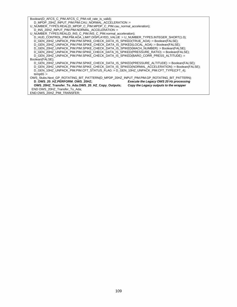
109
Boolean(D_AFCS_C_PIM.AFCS_C_PIM.roll_rate_is_valid); D_MPDP_20HZ_INPUT_PIM.PIM.CAU_NORMAL_ACCELERATION := U_NUMBER_TYPES.REAL(D_MPDP_C_PIM.MPDP_C_PIM.cau_normal_acceleration); D_INS_20HZ_INPUT_PIM.PIM.NORMAL_ACCELERATION := U_NUMBER_TYPES.REAL(D_INS_C_PIM.INS_C_PIM.normal_acceleration); D_HUD_CONTROL_PIM.PIM.AOA_LIMIT.DISPLAYED_VALUE := U_NUMBER_TYPES.INTEGER_SHORT(1.0); D_GEN_20HZ_UNPACK_PIM.PIM.SPIKE_CHECK_DATA_IS_SPIKED(TRUE_AOA) := Boolean(FALSE); D_GEN_20HZ_UNPACK_PIM.PIM.SPIKE_CHECK_DATA_IS_SPIKED(LOCAL_AOA) := Boolean(FALSE); D_GEN_20HZ_UNPACK_PIM.PIM.SPIKE_CHECK_DATA_IS_SPIKED(MACH_NUMBER) := Boolean(FALSE); D_GEN_20HZ_UNPACK_PIM.PIM.SPIKE_CHECK_DATA_IS_SPIKED(PRESSURE_RATIO) := Boolean(FALSE); D_GEN_20HZ_UNPACK_PIM.PIM.SPIKE_CHECK_DATA_IS_SPIKED(BARO_CORR_PRESS_ALTITUDE) := Boolean(FALSE); D_GEN_20HZ_UNPACK_PIM.PIM.SPIKE_CHECK_DATA_IS_SPIKED(PRESSURE_ALTITUDE) := Boolean(FALSE); D_GEN_20HZ_UNPACK_PIM.PIM.SPIKE_CHECK_DATA_IS_SPIKED(NORMAL_ACCELERATION) := Boolean(FALSE); D_GEN_10HZ_UNPACK_PIM.PIM.CFT_STATUS_FLAG := D_GEN_10HZ_UNPACK_PIM.CFT_TYPE(CFT_4); temp65 := OWS_Stubs.Next_GP_ROTATING_BIT_PATTERN(D_MPDP_20HZ_INPUT_PIM.PIM.GP_ROTATING_BIT_PATTERN); D_OWS_20_HZ.PERFORM_OWS_20HZ; Execute the Legacy OWS 20 Hz processing OWS_20HZ_Transfer_To_Ada.OWS_20_HZ_Copy_Outputs; Copy the Legacy outputs to the wrapper END OWS_20HZ_Transfer_To_Ada; END OWS_20HZ_PIM_TRANSFER;