PO Box 66149 St. Louis, MO 63166-6149 May 25, 2000 U.S ...
66
Union Electric One Ameren Plaza 1901 Chouteau Avenue PO Box 66149 St. Louis, MO 63166-6149 May 25, 2000 314.621.3222 U.S. Nuclear Regulatory Commission Attn: Document Control Desk Mail Station P1-137 Washington, D.C. 20555 ULNRC- 04257 Gentlemen: DOCKET NUMBER 50-483 UNION ELECTRIC COMPANY CALLAWAY PLANT BDMS ELIMINATION WAmeren UE Reference: OL Amendment No. 133 dated May 28, 1999, Improved Technical Specifications Union Electric Company herewith transmits an application for amendment to Facility Operating License No. NPF-30 for the Callaway Plant. This amendment application would delete Technical Specification (TS) 3.3.9, "Boron Dilution Mitigation System (BDMS)," and its associated Bases. The BDMS, currently required by 1 OCFR50.36(c)(2)(ii) Criterion 3 for inadvertent boron dilution mitigation, would no longer be credited and the automatic valve swap-over function would be eliminated. Operational details associated with the revised analysis will be contained in FSAR Section 16.3.5 (e.g., one RCS loop must be in operation and two high VCT water level alarm channels must be operable). In lieu of crediting the BDMS for automatic event mitigation, alarms, indicators, procedures and controls will direct a manual response to inadvertent boron dilution transients. The change requested in this amendment application is based upon changes approved for Comanche Peak Steam Electric Station in their OL Amendments 20 and 6 dated November 3, 1993 for Units 1 and 2, respectively, and for Wolf Creek Generating Station in their OL Amendment 96 dated March 1, 1996. Union Electric was involved in the utility subgroup that developed the common methodology used in those plants' BDMS elimination submittals and participated in a joint NRC staff briefing on December 15, 1992 (meeting minutes issued by NRC on February 8, 1993). At that time we elected to retain the automatic system with a lowered flux multiplication setpoint of 1.7, approved in our OL Amendment 94 dated March 7, 1995. However, we now propose to eliminate the BDMS to avoid recurring spurious valve swap-over events, such as the one that occurred during the shutdown for Refuel 9 (on April 3, 1998) resulting in the loss of at least three hours of critical path time. In addition, several spurious valve swap overs also occurred during Refuel 10 (October - November 1999) that were eventually attributed to a malfunctioning switch in the flux multiplication circuitry. This type of a subsidiary of Ameren Corporation
Transcript of PO Box 66149 St. Louis, MO 63166-6149 May 25, 2000 U.S ...
Union Electric One Ameren Plaza 1901 Chouteau Avenue PO Box 66149 St. Louis, MO 63166-6149
May 25, 2000 314.621.3222
U.S. Nuclear Regulatory Commission Attn: Document Control Desk Mail Station P1-137 Washington, D.C. 20555
ULNRC- 04257
Gentlemen:
DOCKET NUMBER 50-483 UNION ELECTRIC COMPANY
CALLAWAY PLANT BDMS ELIMINATION
WAmeren UE Reference: OL Amendment No. 133 dated May 28, 1999,
Improved Technical Specifications
Union Electric Company herewith transmits an application for amendment to Facility Operating License No. NPF-30 for the Callaway Plant.
This amendment application would delete Technical Specification (TS) 3.3.9, "Boron Dilution Mitigation System (BDMS)," and its associated Bases. The BDMS, currently required by 1 OCFR50.36(c)(2)(ii) Criterion 3 for inadvertent boron dilution mitigation, would no longer be credited and the automatic valve swap-over function would be eliminated. Operational details associated with the revised analysis will be contained in FSAR Section 16.3.5 (e.g., one RCS loop must be in operation and two high VCT water level alarm channels must be operable).
In lieu of crediting the BDMS for automatic event mitigation, alarms, indicators, procedures and controls will direct a manual response to inadvertent boron dilution transients. The change requested in this amendment application is based upon changes approved for Comanche Peak Steam Electric Station in their OL Amendments 20 and 6 dated November 3, 1993 for Units 1 and 2, respectively, and for Wolf Creek Generating Station in their OL Amendment 96 dated March 1, 1996. Union Electric was involved in the utility subgroup that developed the common methodology used in those plants' BDMS elimination submittals and participated in a joint NRC staff briefing on December 15, 1992 (meeting minutes issued by NRC on February 8, 1993). At that time we elected to retain the automatic system with a lowered flux multiplication setpoint of 1.7, approved in our OL Amendment 94 dated March 7, 1995. However, we now propose to eliminate the BDMS to avoid recurring spurious valve swap-over events, such as the one that occurred during the shutdown for Refuel 9 (on April 3, 1998) resulting in the loss of at least three hours of critical path time. In addition, several spurious valve swapovers also occurred during Refuel 10 (October - November 1999) that were eventually attributed to a malfunctioning switch in the flux multiplication circuitry. This type of
a subsidiary of Ameren Corporation
-2-
malfunction would no longer result in an RCS boration after implementation of the requested plant modification. This amendment would also eliminate the need for each reload safety evaluation to verify the applicability of Cycle 5 inverse count rate ratio (ICRR) data to each reload core.
Commitments associated with this amendment application are detailed in Section X of the attached Appendix A.
The Callaway Plant Onsite Review Committee and the Nuclear Safety Review Board have reviewed this amendment application. Attachments 1 through 5 provide the Significant Hazards Evaluation, Environmental Consideration, Technical Specification Changes, Draft Technical Specification Bases Changes, and Draft FSAR Chapter 16 Changes, respectively, in support of this amendment request. Attachment 3 mark-ups are based on the amendment referenced above. Attachment 4 mark-ups are provided for information only. Final Bases changes will be implemented under our TS 5.5.14 Bases Control Program after NRC approval of this amendment application. Attachment 5 mark-ups are also provided for information only. It has been determined that this amendment application does not involve a significant hazard consideration as determined per 1OCFR50.92. Pursuant to 1OCFR51.22(b), no environmental impact statement or environmental assessment need be prepared in connection with the issuance of this amendment.
Approval of this amendment application is requested by March 1, 2001. The amendment will be fully implemented prior to entering MODE 5 from MODE 6 during startup from Refuel 11.
If you have any questions on this amendment application, please contact us.
Very truly yours,
Alan C. Passwater Manager-Corporate Nuclear Services
Attachments:
1 - Significant Hazards Evaluation 2 - Environmental Consideration 3 - Technical Specification Changes 4 - Draft Technical Specification Bases Changes 5 - Draft FSAR Chapter 16 Changes
Appendix A - Safety Analysis of the Postulated Inadvertent Boron Dilution Event for MODES 3, 4, and 5
STATE OF MISSOURI ) ) s
CITY OF ST. LOUIS )
Alan C. Passwater, of lawful age, being first duly sworn upon oath says that he is Manager, Corporate Nuclear Services for Union Electric Company; that he has read the foregoing document and knows the content thereof; that he has executed the same for and on behalf of said company with full power and authority to do so; and that the facts therein stated are true and correct to the best of his knowledge, information and belief.
By Alan C. Passwater
Manager, Corporate Nuclear Services
SUBSCRIBED and sworn to before me this day
of , 2000.
MEUISSA L. ORR Notary Public - Notary Seal
STATE OF MISSOURI City of St. Louis
JCommssion Expres: June 23, 2003
cc: M. H. Fletcher L//o Professional Nuclear Consulting, Inc. 19041 Raines Drive Derwood, MD 20855-2432
Regional Administrator w/A U.S. Nuclear Regulatory Commission Region IV 611 Ryan Plaza Drive Suite 400 Arlington, TX 76011-8064
Senior Resident Inspector ./a. Callaway Resident Office U.S. Nuclear Regulatory Commission 8201 NRC Road Steedman, MO 65077
Mr. Jack Donohew (2)- OPEN BY ADDRESSEE ONLY S/S
Office of Nuclear Reactor Regulation U.S. Nuclear Regulatory Commission 1 White Flint, North, Mail Stop OWFN 4D3
11555 Rockville Pike Rockville, MD 20852-2738
Manager, Electric Department w/a
Missouri Public Service Commission P.O. Box 360 Jefferson City, MO 65102
Ron Kucera 1/0
Department of Natural Resources P.O. Box 176 Jefferson City, MO 65102
Denny Buschbaum w•A
TU Electric P.O. Box 1002 Glen Rose, TX 76043
Pat Nugent wtA Pacific Gas & Electric Regulatory Services P.O. Box 56 Avila Beach, CA 93424
I

ATTACHMENT ONE
SIGNIFICANT HAZARDS EVALUATION
Attachment 1 Page 1 of 7
SIGNIFICANT HAZARDS EVALUATION
INTRODUCTION
This amendment application would delete Technical Specification 3.3.9, "Boron Dilution Mitigation System (BDMS)," and its associated Bases. The BDMS, currently required by 10CFR50.36(c)(2)(ii) Criterion 3 for inadvertent boron dilution mitigation, would no longer be credited and the automatic valve swap-over function would be eliminated. Operational details associated with the revised analysis will be contained in FSAR Section 16.3.5 (e.g., one RCS loop must be in operation and two high VCT water level alarm channels must be operable). In lieu of crediting the BDMS for automatic event mitigation, alarms, indicators, procedures and controls will direct a manual response to inadvertent boron dilution transients.
BACKGROUND
Technical Specification 3.3.9 requires that the BDMS be operable to detect and mitigate an inadvertent boron dilution event in MODES 3, 4, and 5 before a complete loss of shutdown margin occurs (i.e., prior to criticality). The system detects an inadvertent boron dilution event by monitoring the output of the source range neutron flux detectors. The BDMS microprocessor monitors the core flux in discrete 1-minute intervals and retains the average monitored flux data for up to 10 of those intervals. The microprocessor compares the flux value in the most recent interval to each of the prior 9 intervals and actuates an alarm and automatic mitigation functions (i.e., valve swapover to terminate dilution and initiate boration) when the flux multiplication setpoint of 1.7 is reached. Valves that isolate the refueling water storage tank (RWST) are opened to supply borated water to the suction of the charging pumps, and valves which isolate the volume control tank (VCT) are closed to terminate the dilution.
The current accident analysis relies on automatic BDMS actuation to mitigate the consequences of inadvertent boron dilution events. As noted in NRC Information Notice (IN) 93-32, various issues have been raised regarding non-conservative assumptions associated with the inverse count rate ratio (ICRR) data and flux-multiplication setpoint uncertainties (latter addressed at Callaway with a lower flux multiplication setpoint of 1.7) used in the analysis.
An alternative approach to reliance on the BDMS was jointly developed and licensed for Comanche Peak Steam Electric Station and Wolf Creek Generating Station. This
Attachment 1 Page 2 of 7
approach is based on the detection of mass imbalances in the chemical and volume control system (CVCS), which is unaffected by the issues discussed in IN 93-32. With the exception of initial and critical boron concentrations, this approach is insensitive to reload-dependent parameters. Because the values of initial and critical boron concentrations can be predicted prior to plant startup, this approach allows for the performance of reload safety evaluations in accordance with 10CFR50.59.
DISCUSSION
Appendix A contains a reanalysis of the inadvertent boron dilution event in MODES 3 through 5 which credits operator action to terminate the dilution after receiving a high VCT water level alarm. The required changes to plant hardware and operating procedures are discussed in Section X of Appendix A. Technical Specification 3.3.9 would be deleted and FSAR Chapter 16 would be revised to reflect operational details associated with the revised analysis. New Section 16.3.5 would contain requirements to have one RCS loop in operation and two high VCT water level alarm channels operable. These operational details are not required to be included in the Technical Specifications since operator action will now be credited for accident mitigation and 1 0CFR50.36(c)(2)(ii) Criterion 3 no longer applies.
The requirement to have at least one RCS loop in operation is related to the mixing volume assumption used in the revised analysis; however, the requirement to isolate the dilution source valves with no RCS loops in operation is already reflected in plant operating procedures. Similar to the conclusion reached in Section 4.E of the ITS Amendment 133 SER discussion of CTS DOC 3-01-R for reactor decay time, a Technical Specification is not required to ensure one RCS loop is in operation while dilutions are possible. The plans for normal facility operation are required to be described in the FSAR per 1OCFR50.34(b)(6)(iv). Controls specified in 1OCFR50.59 apply to changes in procedures as described in the FSAR. The Bases for Technical Specifications 3.4.5, 3.4.6, 3.4.7, and 3.4.8 also reflect the requirement to isolate dilution source valves in MODES 3 through 5 unless at least one RCS loop is in operation. The Bases Control Program (Technical Specification 5.5.14) specifies that 10CFR50.59 will govern the program used to make changes to the Bases.
Likewise, the high VCT water level alarm channels do not trigger any of the screening criteria of 10CFR50.36 (c)(2)(ii). They are indirectly related to Criterion 3; however, the alarms do not mitigate the event. Operator action mitigates the event.
The above documents provide adequate controls over these operational details.
Attachment 1 Page 3 of 7
OPERATOR ACTIONS
The current FSAR analysis credits automatic BDMS actuation to mitigate the consequences of a MODE 3, 4, or 5 inadvertent boron dilution event and credits timely operator actions to mitigate the consequences of a MODE 1 or 2 boron dilution event. The proposed reanalysis of the MODE 3, 4, and 5 inadvertent boron dilution event will credit timely operator actions to terminate the event after a safety-grade high VCT water level alarm is received. Since manual operator actions are being substituted for automatic actions, this amendment application was reviewed against the guidance provided in NRC Information Notice 97-78, "Crediting of Operator Actions in Place of Automatic Actions and Modifications of Operator Actions, Including Response Times." This information notice concludes that proposed changes that substitute manual actions for automatic system actuation previously reviewed and approved by the NRC during the original licensing review of the plant will, in all likelihood, raise the possibility of an unreviewed safety question.
Since manual operator actions are being substituted for automatic actions, unanalyzed failure modes could potentially be introduced through operator acts of omission or commission. However, as discussed in NSAC-183, "Risk of PWR Reactivity Accidents during Shutdown and Refueling," gradual inadvertent boron dilution events are not expected to cause core damage, even if they are unmitigated, due to their self- limiting nature.
The BDMS terminates a MODE 3, 4, or 5 inadvertent boron dilution event by initiating automatic valve swap-over. Valve swap-over consists of opening the RWST isolation valves, then closing the VCT isolation valves. In order for the VCT isolation valves to close automatically, the RWST isolation valves must first be fully open. This valve interlock feature is designed to ensure a flow path is maintained to the centrifugal charging pumps (CCPs) during valve swap-over. Since the VCT isolation valves can be manually closed prior to opening the RWST isolation valves, the possibility exists for the operator to inadvertently isolate flow to the CCPs while attempting to isolate the dilution source. However, plant operating procedures provide the operators with sufficient guidance for performing a manual valve swap-over and the reanalysis demonstrates that sufficient time is available to perform the required manual actions, consistent with the SRP acceptance criteria.
Attachment 1 Page 4 of 7
10CFR50.92 EVALUATION
The proposed change does not involve a significant hazards consideration because operation of Callaway Plant in accordance with this change would not:
1) Involve a significant increase in the probability or consequences of an accident previously evaluated.
Overall protection system performance will remain within the bounds of the previously performed accident analyses since the associated hardware changes described in Section X of Appendix A do not affect any protection systems. The RTS and ESFAS instrumentation will be unaffected. These protection systems will continue to function in a manner consistent with the plant design basis. The installation of an alarm on the letdown divert valve, addition of two redundant high VCT water level alarms, and elimination of the automatic BDMS valve swap-over function will be performed in such a manner that all design, material, and construction standards that were applicable prior to the change are maintained.
The proposed change will modify the system interface between the CVCS and the boron recycle system such that the RCS and CVCS form a closed system consistent with the reanalysis assumptions. The letdown divert valve will be placed in the manual "VCT" mode prior to entry into MODE 3 from MODE 2 during a plant shutdown and prior to entry into MODE 5 from MODE 6 during a plant startup such that letdown flow is directed to the VCT, rather than to the recycle holdup tanks, except under administrative controls for planned evolutions which require a high degree of operator involvement and awareness. These administrative controls will include verification of the boron concentration of the makeup prior to repositioning the divert valve and restoration requirements to return the valve to the manual 'VCT" mode upon evolution completion.
The proposed change will not affect the probability of any event initiators. The above modifications are unrelated to the initiating event for this analysis, a failure in the reactor makeup control system. The change will revise the method of detecting the event and rely on operator action for event termination. There will be no degradation in the performance of or an increase in the number of challenges imposed on safetyrelated equipment assumed to function during an accident situation. There will be no change to normal plant operating parameters or accident mitigation performance.
Since manual operator actions are being substituted for automatic actions, this amendment application was reviewed against the guidance provided in NRC
Attachment 1 Page 5 of 7
Information Notice 97-78, "Crediting of Operator Actions in Place of Automatic Actions and Modifications of Operator Actions, Including Response Times." Appendix A demonstrates that sufficient time is available for operator action to terminate the inadvertent boron dilution event prior to criticality. Additionally, as discussed in NSAC-1 83, "Risk of PWR Reactivity Accidents during Shutdown and Refueling," gradual inadvertent boron dilution events are not expected to cause core damage, even if they are unmitigated, due to their self-limiting nature.
The proposed change will achieve the same objective as the BDMS, i.e., the prevention of an inadvertent criticality as a result of an unintended boron dilution. The proposed change will not alter any assumptions or change any mitigation actions in the radiological consequence evaluations in the FSAR. Appendix A demonstrates that sufficient time is available for operator action to terminate the inadvertent boron dilution event prior to criticality. With the reactor subcritical, there will be no increase in radiological consequences.
Therefore, the proposed change does not involve a significant increase in the probability or consequences of an accident previously evaluated.
2) Create the possibility of a new or different kind of accident from any accident previously evaluated.
There are no changes in the method by which any safety-related plant system performs its safety function. The changes described in Section X of Appendix A have no impact on any analyzed event other than inadvertent boron dilution. The physical modifications to eliminate the automatic BDMS valve swap-over function and add redundant high VCT water level alarms and a position alarm on the letdown divert valve will be implemented in accordance with existing plant design criteria. The BDMS itself has no impact on any other analyzed event. The portion of the change deleting the BDMS from the Technical Specifications, and eliminating the automatic valve swap-over function, has no other impact on plant safety. The BDMS flux multiplication alarm will be retained as a plant design feature to provide the plant operators a diverse method for identifying a potential dilution event. Since the passive alarms to be added only provide information and do not initiate control or protection system actions, the alarms will not adversely impact other events. The position of the letdown divert valve only affects the path for letdown flow. The flow path selected for letdown does not affect any other accident analyses. Thus, the operational change to make the manual "VCT" mode the normal operating condition in MODES 3 through 5 has no safety impact. Procedural changes will heighten the operator awareness of potential dilution events and provide alarm response actions
Attachment 1 Page 6 of 7
to mitigate potential dilution events. As such, these changes will enhance the response to inadvertent boron dilution events, but have no other safety impact. The FSAR Chapter 16 requirements for reactor coolant loop operation and high VCT water level alarm operability will also enhance the plant operators' capability to respond to an inadvertent boron dilution event. If the Chapter 16 requirements are not met, isolating the dilution source valves in MODES 3, 4, and 5 has no impact on any other accident analyses since none of the other accident analyses take credit for, or are initiated by, the flow path through these valves.
This change will affect the normal method of plant operation while in MODES 3 through 5 with regard to the control of letdown flow. In these MODES, letdown processing via the recycle holdup tanks will be allowed only under administrative controls for planned evolutions which require a high degree of operator involvement and awareness. The annunciation of the letdown divert valve not being in the "VCT" position will further highlight system conditions to the operating staff. No other performance requirements will be affected.
In order to automatically close the VCT isolation valves, the RWST isolation valves must first be fully open. This valve interlock feature is designed to ensure a flow path is maintained to the CCPs during valve swap-over. Since the VCT isolation valves can be manually closed prior to opening the RWST isolation valves, the possibility exists for the operator to inadvertently isolate flow to the CCPs while attempting to isolate the dilution source. However, plant operating procedures provide the operators with sufficient guidance for performing a manual valve swap-over and the reanalysis demonstrates that sufficient time is available to perform the required manual actions, consistent with the SRP acceptance criteria.
Therefore, the proposed change does not create the possibility of a new or different kind of accident from any previously evaluated.
3) Involve a significant reduction in a margin or safety.
The proposed change uses acceptance criteria consistent with the Standard Review Plan, as discussed in Appendix A. The margin of safety required of the BDMS is maintained, i.e., inadvertent boron dilution events will be terminated by timely operator actions prior to a total loss of all shutdown margin. There will be no effect on the manner in which safety limits or limiting safety system settings are determined nor will there be any effect on those plant systems necessary to assure the accomplishment of protection functions. There will be no impact on the overpower limit, DNBR limits, FQ, FAH, LOCA PCT, peak local power density, or any other margin of safety. The radiological dose consequence acceptance criteria listed in the Standard Review Plan will continue to be met.
Attachment 1 Page 7 of 7
Therefore, the proposed change does not involve a significant reduction in any margin of safety.
CONCLUSION
Based on the above discussions, it has been determined that the proposed Technical Specification change does not involve a significant increase in the probability or consequences of an accident previously evaluated; or create the possibility of a new or different kind of accident; or involve a significant reduction in a margin of safety. Therefore, this amendment application does not involve a significant hazards consideration.

ATTACHMENT TWO
ENVIRONMENTAL CONSIDERATION

Attachment 2 Page 1 of 1
ENVIRONMENTAL CONSIDERATION
This amendment application would delete Technical Specification 3.3.9, "Boron Dilution Mitigation System (BDMS)," and its associated Bases. The BDMS, currently required by 1 OCFR50.36(c)(2)(ii) Criterion 3 for inadvertent boron dilution mitigation, would no longer be credited and the automatic valve swap-over function would be eliminated. Operational details associated with the revised analysis will be contained in FSAR Section 16.3.5 (e.g., one RCS loop must be in operation and two high VCT water level alarm channels must be operable). In lieu of crediting the BDMS for automatic event mitigation, alarms, indicators, procedures and controls will direct a manual response to inadvertent boron dilution transients.
The proposed amendment involves changes with respect to the use of facility components located within the restricted area, as defined in 10CFR20. Union Electric has determined that the proposed amendment does not involve:
(1) A significant hazards consideration, as discussed in Attachment 1 of this amendment application;
(2) A significant change in the types or significant increase in the amounts of any effluents that may be released offsite;
(3) A significant increase in individual or cumulative occupational radiation exposure.
Accordingly, the proposed amendment meets the eligibility criteria for categorical exclusion set forth in 1OCFR51.22(c)(9). Pursuant to 1OCFR51.22(b), no environmental impact statement or environmental assessment need be prepared in connection with the issuance of this amendment.

ATTACHMENT THREE
TECHNICAL SPECIFICATION CHANGES
S"_ "--b BDMS 3.3.9
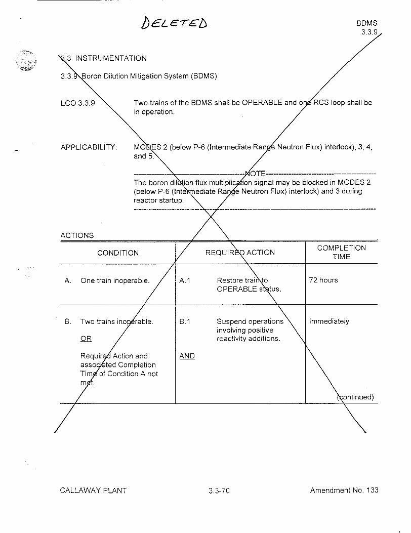
.3 INSTRUMENTATION
3.3. oron Dilution Mitigation System (BDMS)
LCO 3.3.9 Two trains of the BDMS shall be OPERABLE and o RCS loop shall be "in operation.
APPLICABILITY: MO ES 2 (below P-6 (Intermediate Ran Neutron Flux) interlock), 3, 4, and 5.
-- --- ----- ---------------- OTE------- -------- ---
The boron dil ion flux multiplic ion signal may be blocked in MODES 2 (below P-6 (Inte ediate Ra e Neutron Flux) interlock) and 3 during reactor startup.
ACTIONS __URA
CONDITION REQUIR ACTION COMPLETION TIME
A. One train inoperable. A.1 Restore traito 72 hours OPERABLE su.•
B. Two trains ino rable. B.1 Suspend operations Immediately involving positive
OR reactivity additions.
Requir Action and AND asso ited Completion Tim of Condition A not m
_ontinued)
Amendment No. 133CALLAWAY PLANT 3.3-70
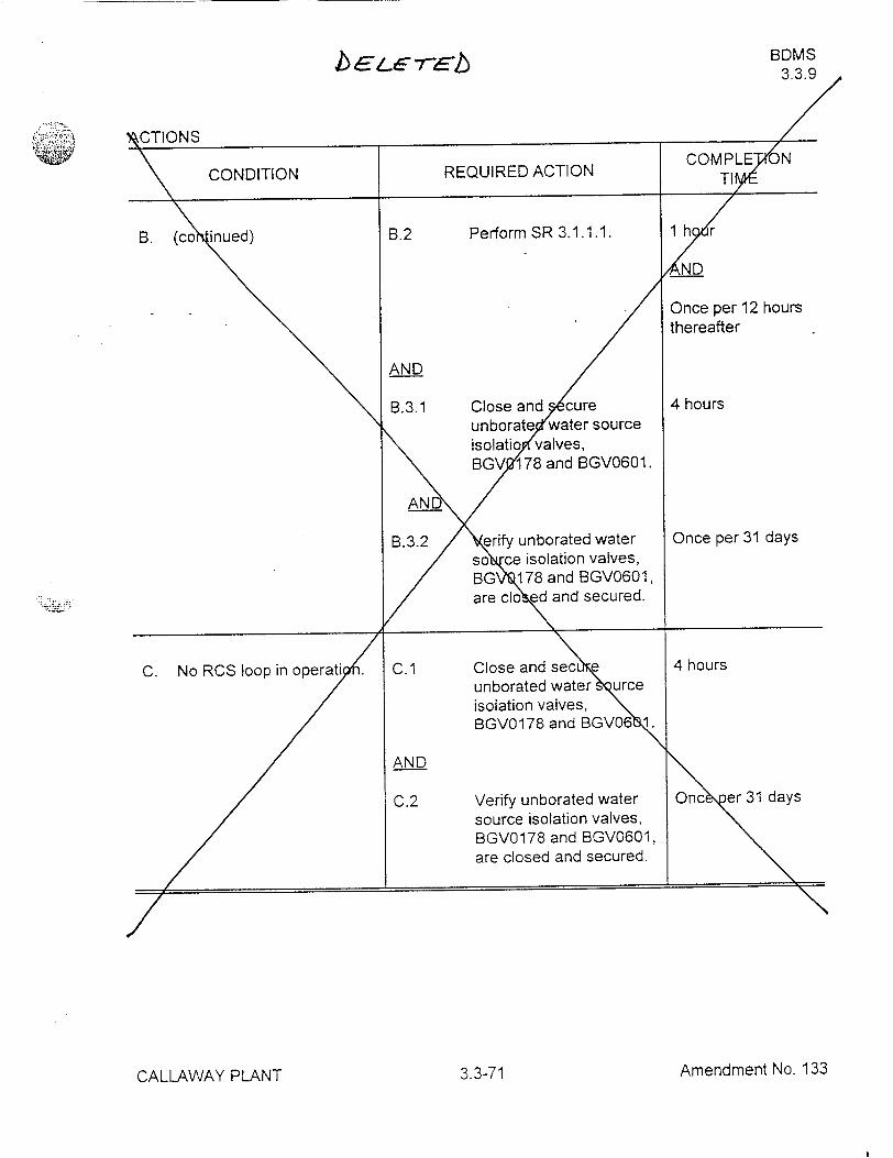
BDMS 3.3.9
Amendment No. 133CALLAWAY PLANT 3.3-71
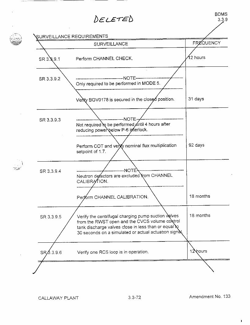
BDMS 3.3.9
URVEILLANCE REQUIREMENTS
SURVEILLANCE F QUENCY
SR 3. .9.1 Perform CHANNEL CHECK. 2 hours
SR 3.3.9.2 -...----------------.------ NOTE-------- ----
Only required to be performed in MODE 5.
OVe BGV0178 is secured in thecs position. 31 days
SR 3.3.9.3 --------------------- ----------Not requre. b performed ntl4hours after
Perform COT and e, nominal flux multiplication 92 days
----- --- -- -------------------- ---------
setpoint of l.7. c iN -re
SR 3.3.9.4Ne R-ar - is in Ope r 1 ours Neutron d cos r xcluded •om CHANNEL
CALIBP ION. \
Pe mCHANNEL CALIBRATION. 18 months
SR 3.3.9.5 /Verify the centrifugal charging pump suction I'ves 18 months / from the RWST open and the CVCS volume co trol
/ tank discharge valves close in less than or equal ; 0\ S; R/.3. 9.6 Verify one RCS loop is in operation. 1\ z3u rs
/-
Amendment No. 133
bE LE -rE-6
.•, • ....
CALLAWAY PLANT 3.3-72
I

ATTACHMENT FOUR
DRAFT TECHNICAL SPECIFICATION BASES CHANGES
SDM B 3.1.1
BASES
APPLICABLE SAFETY ANALYSES
(continued)
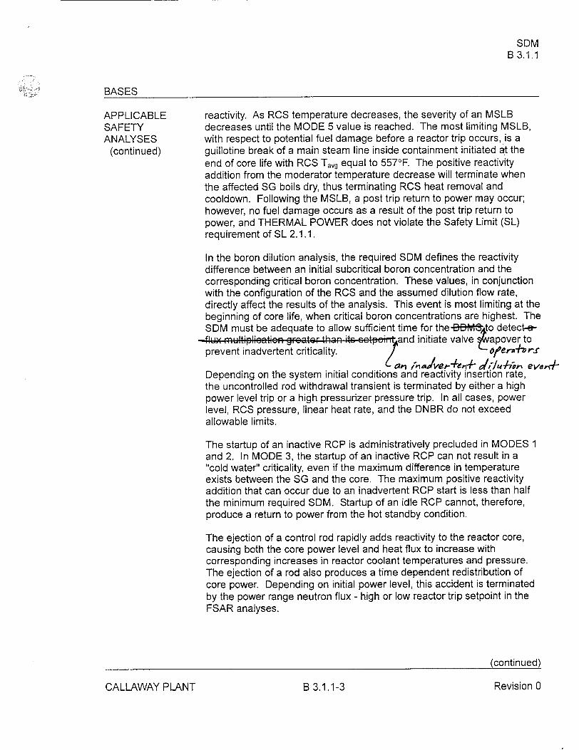
reactivity. As RCS temperature decreases, the severity of an MSLB decreases until the MODE 5 value is reached. The most limiting MSLB, with respect to potential fuel damage before a reactor trip occurs, is a guillotine break of a main steam line inside containment initiated at the end of core life with RCS Tavg equal to 5570F. The positive reactivity addition from the moderator temperature decrease will terminate when the affected SG boils dry, thus terminating RCS heat removal and cooldown. Following the MSLB, a post trip return to power may occur; however, no fuel damage occurs as a result of the post trip return to power, and THERMAL POWER does not violate the Safety Limit (SL) requirement of SL 2.1.1.
In the boron dilution analysis, the required SDM defines the reactivity difference between an initial subcritical boron concentration and the corresponding critical boron concentration. These values, in conjunction with the configuration of the RCS and the assumed dilution flow rate, directly affect the results of the analysis. This event is most limiting at the beginning of core life, when critical boron concentrations are highest. The SDM must be adequate to allow sufficient time for the-Mlff"to detect-a
-flu mmtiplieetic-n gr:,ter than itc ectp:, and initiate valve 4Eapover to prevent inadvertent criticality. ofe"-Vr..X
Depending on the system initial conditions and reactivity insertion rate, the uncontrolled rod withdrawal transient is terminated by either a high power level trip or a high pressurizer pressure trip. In all cases, power level, RCS pressure, linear heat rate, and the DNBR do not exceed allowable limits.
The startup of an inactive RCP is administratively precluded in MODES 1 and 2. In MODE 3, the startup of an inactive RCP can not result in a "cold water" criticality, even if the maximum difference in temperature exists between the SG and the core. The maximum positive reactivity addition that can occur due to an inadvertent RCP start is less than half the minimum required SDM. Startup of an idle RCP cannot, therefore, produce a return to power from the hot standby condition.
The ejection of a control rod rapidly adds reactivity to the reactor core, causing both the core power level and heat flux to increase with corresponding increases in reactor coolant temperatures and pressure. The ejection of a rod also produces a time dependent redistribution of core power. Depending on initial power level, this accident is terminated by the power range neutron flux - high or low reactor trip setpoint in the FSAR analyses.
(continued)
CALLAWAY PLANT B 3.1.1-3 Revision 0
RTS Instrumentation B 3.3.1
BASES
APPLICABLE 5. Source Range Neutron Flux (continued) SAFETY ANALYSES, flux reactor trip may be manually blocked. When the source range LCO, AND trip is blocked, the high voltage to the detectors is also removed. APPLICABILITY
In MODES 3, 4, and 5 with the Rod Control System capable of rod withdrawal or one or more rods not fully inserted, the Source Range Neutron Flux trip Function must also be OPERABLE. If the Rod Control System is capable of rod withdrawal, the Source Range Neutron Flux trip must be OPERABLE to provide core protection against a rod withdrawal accident. If the Rod Control System is not capable of rod withdrawal, the source range detectors are not required to trip the reactor. -I-wz;e, their monitorinAg F~imtieon uet 49e GIPSIRALE to monmitef eerz neutreo eveis a id-pi avide I1putb LO th! BM 3 ;d5cIooJ asLCCes m ~ 3.3.9,
"--!Bcro)* Diuto1 Mitigat~vo C~yteii(D MC)," to prteet au-iis mn .tcr.t , ,,tiity ... g.5 t.8t m Y ,-,ou aG a r,,lt of events 4ik , am toimt,•,,, L, 1ua, diul.iuii. The requirements for the NIS source range detectors in MODE 6 are addressed in LCO 3.9.3, "Nuclear Instrumentation."
6. Overtemperature AT
The Overtemperature AT trip Function is provided to ensure that the design limit DNBR is met. This trip Function also limits the range over which the Overpower AT trip Function must provide protection. The inputs to the Overtemperature AT trip include pressure, coolant temperature, axial power distribution, and reactor power as indicated by loop AT assuming full reactor coolant flow. Protection from violating the DNBR limit is assured for those transients that are slow with respect to delays from the core to the measurement system. The Overtemperature AT trip Function uses each loop's AT as a measure of reactor power and is compared with a setpoint that is automatically varied with the following parameters:
reactor coolant average temperature - the Trip Setpoint is varied to correct for changes in coolant density and specific heat capacity with changes in coolant temperature;
pressurizer pressure - the Trip Setpoint is varied to correct for changes in system pressure; and
(continued)
CALLAWAY PLANT Revision 0B 3.3.1-13
.e .E1'reb BDMS .3.9
B 3.3 INSTRUMENTATION
B .3.9 Boron Dilution Mitigation System (BDMS)
BASES
BACKGROU The primary purpose of the BDMS is to miti ate the consequences of the inadvertent addition of unborated primar rade water into the Reactor Coolant System (RCS) when the plant i in MODES 2 (below P-6 setpoint), 3, 4, and 5.
Th BDMS utilizes two channels source range instrumentation. Each sour range channel provides signal to its microprocessor, which continu usly records the cou per minute. At the end of each discrete one-minu interval, an algo hm compares the average counts per minute valu (flux rate) of at 1 minute interval with the average counts per minute va e for the revious nine, 1 minute intervals. If the flux rate during a 1 minu inte al is greater than or equal to 1.7 times the flux rate during any of prior nine 1 minute intervals, the BDMS provides a signal to initiate mi ting actions.
Upon detectio of a flux ultiplication by either source range instrumentati n train, an al mn is sounded to alert the operator and valve movement' automatically in *ated to terminate the dilution and start boration. alves that isolate th refueling water storage tank (RWST) are pumpad valve~sowhich isolate th oum Control Tank are closed ton
ter *ate te diltion
APPLICABLE he BDMS senses abnormal increases in s rce range counts per minute SAFETY (flux rate) and actuates VCT and RWST valve to mitigate the ANALYSES consequences of an inadvertent boron dilution e nt as described in
Reference 1. The accident analyses rely on auto tic BDMS actuation to mitigate the consequences of inadvertent boron diluu n events. The operation of one RCS loop in MODES 2 (beo P -6 se oint), 3, 4, and 5 provides adequate flow to ensure mixing, prevnt strati a tion, and produce gradual reactivity changes during RCS boron con entration reductions. The reactivity change rate associated with boro reduction will, therefore, be within the transient mitigation capability of t BDMS. With no reactor coolant loop in operation in the above MDES, oron dilutions must be terminated and dilution sources isolatd The bron dilution analysis in these MODES takes credit for the mixing volum associated with having at least one reactor coolant loop in operation.
(continued)
CALLAWAY PLANT B 3.3.9-1 Revision 0
BDMS B 3.3.9
EýSES
APP CABLE The event is successfully terminated after the volume of wate rom the e e e SAFE normally closed RWST suction isolation valves to the RCS ia the normal n h
lit R0e
t r
t h is ANALYS S charging flow path is purged and inadvertent criticality is oided. The
u ta
CT suctio
r 'o r'
st pu ou
fo t
vf wate
c it c I ume of (
S a the rt
oided . (continue primary success path for mitigation is fulfilled when the CT suction path
'eva'v
es hitt0
hn
ent e
Ifi
Iled
is isolated; however, the analysis also accounts for t volume of CVCS wc
Zn e b piping from the RWST to the RCS that must bbee pu eedd since its boron
umy
content is dependent on time in cycle life and m itself represent a Csi s dilution source.
ts r 0
he BDMS satisfies Criterion 3 of 10CFR 36(c)(2)(ii). rv(c)( )(ii).
LCO .3.9 provides the requiremen for OPERABILITY of the instru ntation that provides con ol room indication of core neutron levels, a that mitigates the c sequences of a boron dilution event. Two redun ant trains are req red to be OPERABLE to provide protection against sing failure. In a ition, LCO 3.3.9 requires that one RCS loop shall be in op ation.
Because the BD lizes the source range instrumentation in its detection system, t OPERABILITY of that portion of the detection system is also pa o the OPERABILITY of the Reactor Trip System. The flux multiplicati alggo hm, the alarms, and signals to the motor control centers for th suction v Ives all must be OPERABLE for a train in the system to b considered PERABLE. As required for this LCO, the BDMS e nds to, and incld es, the RWST suction isolation valves (BNLCV 112D, E) and the V T suction isolation valves (BGLCV0112B, C).
Wi insufficient RCS mixing volu i.e. no RCS loop in operation, C ldition C must be entered.
APPLICABILITY The BDMS must be OPERABLE in MOD S 2 (below P-6 setpoint), 3, 4, and 5 because the safety analysis identifie this system as the primary means to mitigate an inadvertent boron dilut n of the RCS.
The BDMS OPERABILITY requirements are no applicable in MODES I and 2 (above P-6 setpoint) because an inadverte t boron dilution would be terminated by Overtemperature AT or operator ction. The Overtemperature AT trip Function is discussed in L 3.3.• , "RTS Instrumentation."
ontinued)
CALLAWAY PLANT
LCO
7
©
Revision OaB 3.3.9-2
BDMS B 3.3.9SE &5-re b
BASES
PLICABILITY (ntinued)
In MODE 6, a dilution event is precluded by locked valv (BGV0178 and t e ke
p I d a
BGV0601) that isolate the RCS from the potential sou e of unborated water (according to LCO 3.9.2, "Unborated Water S rce Isolation Valves").
ud teot
te The Applicability is modified by a Note that all s the boron dilution flux
IV
r clý
multiplication signal to be blocked during re tor startup in MODE 2 (below P-6 setpoint) and MODE 3. Blocki g the flux multiplication signal is acceptable during startup provid _ ed th / reactor trip breakers are closed with the intent to withdraw rods for st up. The P-6 interlock provides a backup block signal to the source ra ge flux multiplication circuit.
ACTIONS he most common cause of c nnel inoperability is outright failure or drift o the bistable or process mo ule sufficient to exceed the tolerance all wed by the unit specific, alibration procedure. Typically, the drift is foun to be small and res ts in a delay of actuation rather than a total loss o function. This d ermination of setpoint drift is generally made during e performanc of a COT when the process instrumentation is set up for a stment to ring it to within specification. If the Trip Setpoint is less conse ative t n the tolerance specified by the calibration procedure, te ch nnel must be declared inoperable immediately and the appropriate C ition entered.
With on train of the MS inoperable, Required Action A.1 requires that the in erable train mu be restored to OPERABLE status within 72 h urs. In this Conditio,, the remaining BDMS train is adequate to pro ide protection. The 72 our Completion Time is based on the BDMS F nction and is consistent wi Engineered Safety Feature Actuation
ystem Completion Times for ss of one redundant train. Also, the remaining OPERABLE train pro ides continuous indication of core power status to the operator, has an alar function, and sends a signal to both trains of the BDMS to assure syste actuation.
B.1, B.2, B.3.1, and B.3.2
With two trains inoperable, or the Required ction and associated Completion Time of Condition A not met, the i 'tial action (Required Action B.1) is to suspend all operations involvin positive reactivity additions immediately. This includes withdrawal control or shutdown rods and intentional boron dilution.
(continued)
('A[ I MA\/AV 1D1 AKIT D ' rx vl n 1 -; U•'J "LS..&--X \ ¥ Vl \ I I I..J•LI I I UMVI•iJ I U
BDMS 'E T~r 2 B 3.3.9
BA,`S
ACTIOC B.1, B.2, B.3.1, and B.3.2 (continued)
Required Action B.2 verifies the SDM according to S .1.1.1 within 1 hour and once per 12 hours thereafter. This actioyis intended to confirm that no unintended boron dilution has oc rred while the BDMS was inoperable, and that the required SDM ha een maintained. The specified Completion Time takes into conside tion sufficient time for the initial determination of SDM and other infor ation available in the control oorm related to SDM.
Re uired Action B.3.1 requires valve isted in LCO 3.9.2 (Required Acti A.2), BGV0178 and BGV060 , to be secured to prevent the flow of unbo ted water into the RCS. 0 ce it is recognized that two trains of the BDMS re inoperable, the oper ors will be aware of the possibility of a boron dil tion, and the 4 hour ompletion Time is adequate to complete the requir ents of LCO 3. . . The recurring 31 day verification of Required A *on B.3.2 enst s these valves remain closed for an extended Co ition B e
C.1 and C.2
Condition C is e tere with no RCS loop in operation. The operation of one RCS loop rovides dequate flow to ensure mixing, prevent stratification,, nd produc gradual reactivity changes during RCS boron concentrati nreductions. he reactivity change rate associated with boron red ction will, therefo , be within the transient mitigation capability of the B ron Dilution Mitigatio System (BDMS). With no reactor coolant loop i operation, dilution sourc s must be isolated. The boron dilution anall is takes credit for the mix<in volume associated with having at least oon reactor coolant loop in operati
equired Action C.1 requires that val s BGVO178 and BGV0601 be closed and secured to prevent the flow f unborated water into the RCS. The 4 hour Completion Time is adequate o perform these local valve manipulations. The recurring 31 day verifi tion of Required Action C.2 ensures these valves remain closed and sec red for an extended Condition C entry.
(continued)
CALLAWAY PLANT Revision 0B 3.3.9-4
BDMS B 3.3.9
B\SES (continued)
SUR EILLANCE The BDMS trains are subject to a CHANNEL CHECK, val closure in REQU EMENTS MODE 5, COT, CHANNEL CALIBRATION, and Respon lime Testing.
In addition, the requirement to verify one RCS loop in peration is subject to periodic surveillance.
SR 3.3.9.1
Performance of the CHANNEL CHECK on e every 12 hours ensures that "ross failure of source range instrument ion has not occurred.
A HANNEL CHECK is normally a c parison of the parameter indicated on e channel to a similar parame er on other channels. It is based on the a sumption that instrument c nnels monitoring the same parameter should ead approximately the me value. Significant deviations between he two instrument c nnels could be an indication of excessive instrumen drift in one of the hannels or of something even more serious. A CHANN CHECK will tect gross channel failure; thus, it is key to verifying that he instrum ntation continues to operate properly between each CHANN CALIB TION.
Agreement criteri e determined by the unit staff based on a combination of the hannel instrument uncertainties, including indication and readability. I a annel is outside the criteria, it may be an indication that the sensor r the ignal processing equipment has drifted outside its lim it.
The Frequ cy is based o operating experience that demonstrates channel f lure is rare. The HANNEL CHECK supplements less formal, but mor frequent, checks of annels during normal operational use of the di lays associated with th LCO required channels.
S 3.3.9.2
SR 3.3.9.2 requires that valve BGV0178"e secured and closed prior to entry into MODE 5. Specification 3.9.2 re1ires that this valve also be secured and closed in MODE 6. Closing B V0178 satisfies the boron dilution accident analysis assumption that flo orifice BGFOO010 limits the dilution flow rate to no more than 150 gpm i MODE 5. This Surveillance demonstrates that the valve is close through a system walkdown. SR 3.3.9.2 is modified by a Note statin that it is only required to be performed in MODE 5. This Note requires that e surveillance be performed prior to entry into MODE 5 and every 31 da while in MODE 5. The 31 day frequency is based on engineerin 'udgment and is
continued)
CALLAWAY PLANT B 3.3.9-5 Revision 0
BDMS _B B 3.3.9
ASES
SU VEILLANCE SR 3.3.9.2 (continued) REQ IREMENTS
considered reasonable in view of other administrative co rols that will ensure that the valve opening is an unlikely possibility.
SR 3.3.9.3
SR 3.3.9.3 requires the performance of a CO every 92 days, to ensure at each train of the BDMS and associate trip setpoints are fully
o rational. A successful test of the req i ed contact(s) of a channel relay ma be performed by the verification of e change of state of a single conta of the relay. This clarifies wh is an acceptable CHANNEL OPE IONAL TEST of a relay. T is is acceptable because all of the other req ired contacts of the rel are verified by other Technical Specificati s and non-Technic Specifications tests at least once per refueling inte al with applica extensions. This test shall include verification tha the boron di tion flux multiplication setpoint is equal to or less than an inc ase of 1 times the count rate within a 10 minute period. The 1.7 fli mul Iplication setpoint is a nominal value. SR 3.3.9.3 is met if the measu d etpoint is within a two-sided calibration tolerance band on either side ohe nominal value. SR 3.3.9.3 is modified by a Note that provides 4 ur delay in the requirement to perform this Surveillance after educi power below the P-6 interlock. This Note allows a delay i thee perfo ance of the COT to reflect the delay allowed for the s rce ae chane . If the plant is to remain below the P-6 setpoint for P1ore than 4 hour this Surveillance must be performed prior to 4 hours er reducing powe elow the P-6 setpoint. The Frequency of 92 days i consistent with the re irements for source range channels in Refere e 2.
S 3.3.9.4
R 3.3.9.4 is the performance of a CHAN L CALIBRATION every 18 months. CHANNEL CALIBRATION is a mplete check of the instrument loop, including the sensor. The te verifies that the channel responds to a measured parameter within the n cessary range and accuracy. The SR is modified by a Note that neu on detectors are excluded from the CHANNEL CALIBRATION.
The CHANNEL CALIBRATION for the source range n tron detectors consists of obtaining integral bias curves, evaluating tho e curves, and comparing the curves to the manufacturer's data. The 18 onth Frequency is based on operating experience and on the ne dto obtain
(c ntinued)
CALLAWAY PLANT B 3.3.9-6 Re~vi n 0
BDMS
"B•SES
SUR • ILLANCE SR 3.3.9.4 (c ni u d
RE~ ,,.• _, •lU~ ,,I:N~q integral bias curves under the conditions that apply riga plant outage.
p The other remaining portions of the CHANNEL C BRATION may be
pe rfo rm ed either d uring a pla nt o utag e d uo r d uri pla nt o e a i n
Soeation
S•RR_ .9.5 is the performance of a ponse time test every 18 months to
verify that, on a simulated or act I, b o~l ron dilution flux multiplication
signal, th ,centrifugal chargin ump suction valves from the RWST open
and th C volum o t/• tank discharge valves close in the required
time of < ! 30 se nds to rect the analysis requirements of Reference 1.
T eFrequency is b n operating experience and consistency with
the typical indust ligcycle.
SR 3.3. .requires verification eveo 12 hours that one RCS loop is in
0pe ra . n Verification m ayficl d rate,te p r u eo p mp s a s
mo .r ig which help ensure that forc ~flow is providing adequate
m/i ng. The Frequency of 12 hours is sufient considering other
.dications and alarms available to the oper rin the control room to
monitor RCS loop performance.a'
REFERENC 1. FSAR, Section 15.4.6.
2. Callaway OLAmendment No. 17 dated September 1986.
CALLAWAY PLANT B 3.3.9-7 Revision 0
RCS Loops - MODE 3 B 3.4.5
qGrWh3r..r.BASES
APPLICABLE SAFETY ANALYSES
(continued)
LCO
changes during RCS boron conce ration reductions. The reactivity change rate associated with boron Leduction will, therefore, be within the transient mitigation capability of th -oro.n Dilutin ,t.1ti- 9. Syctom *gQMVS;ý With no reactor coolant loop in operation in either MODES 3, 4, or 5, boron dilutions must be terminated and dilution sources isolated. The boron dilution analysis in these MODES takes credit for the mixing volume associated with having at least one reactor coolant loop in operation. 4-Q )34.9, "B•f,, n Dilutisin Mitigatiwn Systemr- B,-. containi the roquiromonto fzrf thzý 130MG.
Failure to provide decay heat removal may result in challenges to a fission product barrier. The RCS loops are part of the primary success path that functions or actuates to prevent or mitigate a Design Basis Accident or transient that either assumes the failure of, or presents a challenge to, the integrity of a fission product barrier.
RCS Loops - MODE 3 satisfy Criterion 3 of 10CFR50.36(c)(2)(ii).
The purpose of this LCO is to require that at least two RCS loops be OPERABLE. In MODE 3 with the Rod Control System capable of rod withdrawal, two RCS loops must be in operation. Two RCS loops are required to be in operation in MODE 3 with the Rod Control System capable of rod withdrawal due to the postulation of a power excursion because of an inadvertent control rod withdrawal. The required number of RCS loops in operation ensures that the Safety Limit criteria will be met for all of the postulated accidents.
When the Rod Control System is not capable of rod withdrawal, only one RCS loop in operation is necessary to ensure removal of decay heat from the core and homogenous boron concentration throughout the RCS. An additional RCS loop is required to be OPERABLE to ensure that redundancy for heat removal is maintained.
The Note permits all RCPs to be removed from operation for < 1 hour per 8 hour period. The purpose of the Note is to perform tests that are required to be performed without flow or pump noise. One of these tests is validation of the pump coastdown curve used as input to a number of accident analyses including a loss of flow accident. This test is generally performed in MODE 3 during the initial startup testing program, and as such should only be performed once. If, however, changes are made to the RCS that would cause a change to the flow characteristics of the RCS, the input values of the coastdown curve must be revalidated by conducting the test again.
(continued)
CALLAWAY PLANT
BASES.
B 3.4.5-2 Revision 0
RCS Loops - MODE 4 B 3.4.6
B 3.4 REACTOR COOLANT SYSTEM (RCS)
B 3.4.6 RCS Loops - MODE 4
BASES
BACKGROUND In MODE 4, the primary function of the reactor coolant is the removal of
decay heat and the transfer of this heat to either the steam generator (SG) secondary side coolant or the component cooling water via the
residual heat removal (RHR) heat exchangers. The secondary function of
the reactor coolant is to act as a carrier for soluble neutron poison, boric acid.
The reactor coolant is circulated through four RCS loops connected in
parallel to the reactor vessel, each loop containing an SG, a reactor coolant pump (RCP), and appropriate flow, pressure, level, and temperature instrumentation for control, protection, and indication. The RCPs circulate the coolant through the reactor vessel and SGs at a sufficient rate to ensure proper heat transfer and to prevent boric acid stratification.
In MODE 4, either RCPs or RHR loops can be used to provide forced circulation. The intent of this LCO is to provide forced flow from at least one RCP or one RHR loop for decay heat removal and transport. The
flow provided by one RCP loop or RHR loop is adequate for decay heat removal. The other intent of this LCO is to require that two paths be available to provide redundancy for decay heat removal.
APPLICABLE SAFETY ANALYSES
In MODE 4, RCS circulation is considered in the determination of
the time available for mitigation of the accidental boron dilution event. of- r040r.
The operation of one RCP in MO ES 3, 4, and 5 provides adequate flow to ensure mixing, prevent stratifica ion, and produce gradual reactivity changes during RCS boron concentration reductions. The reactivity change rate associated with boron •eduction will, therefore, be within the transient mitigation capability of thd S.ron D. luiz. . .Mitigationmq.. .... .. . m
~46G- With no reactor coolant loop in operation in either MODES 3, 4,
or 5, boron dilutions must be terminated and dilution sources isolated. The boron dilution analysis in these MODES takes credit for the mixing volume associated with having at least one reactor coolant loop in operation. LC--3.8.9, ..... ...lu ... Mitigatio Systom i DBB 1),"
oper ...... t.e ,. , .
RCS Loops -MODE 4 satisfies Criterion 4 of 1OCFR50.36(c)(2)(ii).
(continued)
Revision 0CALLAWAY PLANT
3
._1-
B 3.4.6-1
RCS Loops - MODE 5, Loops Filled B 3.4.7
BASES (continued)
APPLICABLE SAFETY ANALYSES
In MODE 5, RCS circulation is considered in the determination of the time available for mitigation of the accidental boron dilution event.
The operation of one RCP in MOD S 3, 4, and 5 provides adequate flow to ensure mixing, prevent stratifica on, and produce gradual reactivity changes during RCS boron concen lration reductions. The reactivity change rate associated with boron ILduction will, therefore, be within the transient mitigation capability of th"oron D,,t'c-,. ,it.t System
-BBEý- With no reactor coolant loop in operation in either MODES 3, 4, or 5, boron dilutions must be terminated and dilution sources isolated. The boron dilution analysis in these MODES takes credit for the mixing volume associated with having at least one reactor coolant loop in operation. -LG ;.8.9, " o,&,, B . luti.. Mit,.ato. _, ,..._ : j (,-,39h),"
1 1- I I- ' uj a•1i i l l IU I LIIl D IJ IV I -. .
RCS Loops - MODE 5 (Loops Filled) satisfies Criterion 4 of 1 OCFR50.36(c)(2)(ii).
The purpose of this LCO is to require that at least one of the RHR loops be OPERABLE and in operation with an additional RHR loop OPERABLE or two SGs with secondary side wide range water level >_ 66%. As shown in Reference 3, any narrow range level indication above 4% will ensure the SG tubes are covered. One RHR loop provides sufficient forced circulation to perform the safety functions of the reactor coolant under these conditions. An additional RHR loop is required to be OPERABLE to meet single failure considerations. However, if the standby RHR loop is not OPERABLE, an acceptable alternate method is two SGs with their secondary side wide range water levels >_ 66%. Should the operating RHR loop fail, the SGs could be used to remove the decay heat via natural circulation.
Note 1 permits all RHR pumps to be removed from operation ___ 1 hour per 8 hour period. The purpose of the Note is to permit tests that are required to be performed without flow or pump noise. The 1 hour time period is adequate to perform the necessary testing, and operating experience has shown that boron stratification is not likely during this short period with no forced flow.
Utilization of Note 1 is permitted provided the following conditions are met, along with any other conditions imposed by test procedures:
(continued)
CALLAWAY PLANT
LCO
B 3.4.7-2 Revision 0
ý ^ýR a IM
RCS Loops - MODE 5, Loops Not Filled B 3.4.8
B 3.4 REACTOR COOLANT SYSTEM (RCS)
B 3.4.8 RCS Loops - MODE 5, Loops Not Filled
BASES
BACKGROUND
APPLICABLE SAFETY ANALYSES
In MODE 5 with the RCS loops not filled, the primary function of the reactor coolant is the removal of decay heat generated in the fuel, and the transfer of this heat to the component cooling water via the residual heat removal (RHR)'heat exchangers. The steam generators (SGs) are not available as a heat sink when the loops are not filled. The secondary function of the reactor coolant is to act as a carrier for the soluble neutron poison, boric acid.
In MODE 5 with loops not filled, only RHR pumps can be used for coolant circulation. The number of pumps in operation can vary to suit the operational needs. The intent of this LCO is to provide forced flow from at least one RHR pump for decay heat removal and transport and to require that two paths be available to provide redundancy for heat removal.
In MODE 5, RCS circulation is considered in the determination of the time available for mitigation of the accidental boron dilution event. The flow provided by one RHR loop is adequate for decay heat removal.
a Ofe ,-iora+ ,. The operation of one RCP in MOD S 3,4, and 5 provides adequate flow to ensure mixing, prevent stratificat n, and produce gradual reactivity changes during RCS boron concentration reductions. The reactivity change rate associated with boron rduction will, therefore, be within the transient mitigation capability of the or.n. ........ Mit ......n Sy.to..
-ýB+III With no reactor coolant loop in operation in either MODES 3, 4, or 5, boron dilutions must be terminated and dilution sources isolated. The boron dilution analysis in these MODES takes credit for the mixing volume associated with having at least one reactor coolant loop in operation. mCO 3.3.9, o"sro•" . r t M..,3-- (. .m. ... L~.• e, ~ J.4l.l -V II:C:IIIII gý1-ll -U -I•
�MLJIr�rIP�I iL.� I�.JI LI I� LJL.�IVI'.J.
RCS loops in MODE 5 (loops not filled) satisfies Criterion 4 of 1 OCFR50.36(c)(2)(ii).
LCO The purpose of this LCO is to require that at least two RHR loops be OPERABLE and one of these loops be in operation. An OPERABLE loop is one that has the capability of transferring heat from the reactor coolant at a controlled rate. Heat cannot be removed via the RHR System unless forced flow is used. A minimum of one running RHR pump meets the
(continued)
CALLAWAY PLANT B 3.4.8-1
: :Z: :: ..... . .-. •
Revision 0
Nuclear Instrumentation B 3.9.3
BASES
LCO (continued)
Monitor(s) are acceptable equivalent control room indication(s) for Westinghouse Source Range Neutron Flux Monitor(s) in MODE 6, including CORE ALTERATIONS, with the complete fuel assembly inventory set within the reactor vessel or with the Gamma Metrics Source Range Neutron Flux Monitor(s) coupled to the core. Reactor Engineering shall determine whether each monitor is coupled to the core.
APPLICABILITY In MODE 6, the source range neutron flux monitors must be OPERABLE to determine changes in core reactivity. In other modes, the source range monitors are governed by LCO 3.3.1, LCO 3 .3 .3 ,ALCO 3.3.4,.-eA.,I 8.8.9. Ara
ACTIONS A. 1 and A.2
With only one source range neutron flux monitor OPERABLE, redundancy has been lost. Since these instruments are the only direct means of monitoring core reactivity conditions, CORE ALTERATIONS and positive reactivity additions must be suspended immediately. Performance of Required Action A.1 shall not preclude completion of movement of a component to a safe position.
B. 1
With no source range neutron flux monitor OPERABLE, action to restore a monitor to OPERABLE status shall be initiated immediately. Once initiated, action shall be continued until a source range neutron flux monitor is restored to OPERABLE status.
B.2
With no source range neutron flux monitor OPERABLE, there areno direct means of detecting changes in core reactivity. However, since CORE ALTERATIONS and positive reactivity additions are not to be made, the core reactivity condition is stabilized until the source range neutron flux monitors are OPERABLE. This stabilized condition is determined by performing SR 3.9.1.1 to ensure that the required boron concentration exists.
The Completion Time of once per 12 hours is sufficient to obtain and analyze a reactor coolant sample for boron concentration and ensures that unplanned changes in boron concentration would be identified. The
(continued)
Revision 0CALLAWAY PLANT B 3.9.3-2

ATTACHMENT FIVE
DRAFT FSAR CHAPTER 16 CHANGES
BORON DILUTION ANALYSIS
16.3.5.1 LIMTING CONDITION FOR OPERATION
One RCS loop shall be in operation and two high VCT water level alarm channels shall be OPERABLE.
APPLICABILITY: MODES 3, 4, and 5.
ACTION: With one high VCT water level alarm channel inoperable, restore the inoperable channel to OPERABLE status within 72 hours.
With that completion time not met OR with no RCS loop in operation OR with no high VCT water level alarm channel OPERABLE, close and secure the unborated water source isolation valves, BGV0178 and BGV0601, within 4 hours and verify the unborated water source isolation valves are closed and secured once per 31 days.
16.3.5.1.1 SURVEILLANCE REQUIREMENTS
16.3.5.1.1.a
16.3.5.1.1.b
Verify a minimum of one RCS loop is in operation at least once per 12 hours.
The high VCT water level alarm channels shall be demonstrated OPERABLE by performance of a CHANNEL CALIBRATION at least once per 18 months.
16.3.5.1.2 BASES
The accident analyses rely on operator action to mitigate the consequences of inadvertent boron dilution events. The operation of one RCS loop provides adequate flow to ensure mixing, prevent stratification, and produce gradual reactivity changes during RCS boron concentration reductions. The reactivity change rate associated with boron reduction will, therefore, be within the analyzed operator response time capability after receipt of a high VCT water level alarm. With no reactor coolant loop in operation or no OPERABLE high VCT water level alarm, dilution sources must be isolated. The boron dilution analyses
16.3.5
take credit for the mixing volume associated with having at least one reactor coolant loop in operation and for operator notification of an inadvertent dilution event by the high VCT water level alarm.
The event is successfully terminated by the operator after the volume of water from the normally closed RWST suction isolation valves to the RCS via the normal charging flow path is purged and inadvertent criticality is avoided. The primary success path for mitigation is fulfilled when the VCT suction path is isolated; however, the analysis also accounts for the volume of CVCS piping from the RWST or boric acid tanks to the RCS that must be purged since its boron content is dependent on time in cycle life and may itself represent a dilution source.
In MODES 1 and 2, reactor trips and subsequent operator actions are credited as discussed in Section 15.4.6. In MODE 6, a dilution event is precluded by locked valves (BGV0178 and BGV0601) that isolate the RCS from the potential source of unborated water (according to Technical Specification LCO 3.9.2, "Unborated Water Source Isolation Valves").
The ACTION is entered with no RCS loop in operation or inoperable high VCT water level alarm channel(s). The ACTION requires one inoperable high VCT water level alarm channel to be restored to OPERABLE status within 72 hours. If that completion time is not met or if no RCS loop is in operation or if both high VCT water level alarm channels are inoperable, the ACTION requires that valves BGV0178 and BGV0601 be closed and secured to prevent the flow of unborated water into the RCS. The 4 hour completion time is adequate to perform these local valve manipulations. The recurring 31 day verification ensures these valves remain closed and secured for an extended ACTION entry.
A verification shall be performed every 12 hours that one RCS loop is in operation. Verification may include flow rate, temperature, or pump status monitoring, which help ensure that forced flow is providing adequate mixing. The Frequency of 12 hours is sufficient considering other indications and alarms available to the operator in the control room to monitor RCS loop performance.
A CHANNEL CALIBRATION on the high VCT water level alarm channels shall be performed every 18 months. A CHANNEL CALIBRATION is a complete check of the instrument loop, including the sensor. The test verifies that the channel responds to a measured parameter within the necessary range and accuracy.
APPENDIX A
SAFETY ANALYSIS OF THE POSTULATED INADVERTENT BORON DILUTION EVENT
FOR MODES 3,4, AND 5
Table of Contents
I. Introduction and Background 1
I1. Regulatory Basis 2
III. Event Description 4
IV. Description of RMCS Design and Operation 6
V. Detection of an Inadvertent Boron Dilution Event 8 in MODE 3, 4, and 5
VI. Inadvertent Boron Dilution Event Scenarios 9
VII. Equipment Design 13
VIII. Method of Analysis 13
IX. Callaway-Specific Analysis Inputs and Results 22
X. Callaway-Specific Actions Required for Implementation 26
XI. Summary 27

I. Introduction and Background
The inadvertent boron dilution event is considered in the licensing basis of Callaway Plant. This event is postulated to be initiated by a malfunction in the Chemical and Volume Control System (CVCS) which results in a decrease in the boron concentration of the Reactor Coolant System (RCS). The possibility of this event is considered for all modes of plant operation except MODE 6, during which inadvertent dilutions are administratively precluded by valve closure per Technical Specification (TS) 3.9.2.
Several studies have been performed concerning the risk associated with inadvertent boron dilution events, particularly during shutdown and refueling. Among the most recent is NSAC-183 (December 1992), "Risk of PWR Reactivity Accidents during Shutdown and Refueling." Several conclusions of this report are relevant to the analysis of the inadvertent boron dilution event:
1) Due to their self-limiting nature, gradual inadvertent boron dilution events are not expected to cause core damage, even if they are unmitigated.
2) No inadvertent criticalities have resulted from any of the gradual inadvertent boron dilution events that have occurred.
3) The frequency of gradual inadvertent boron dilution events reported at commercial nuclear plants in the United States has declined significantly. The frequency of an inadvertent criticality from an inadvertent boron dilution event is expected to be less than 1 E-4 per reactor year.
In the current accident analysis (FSAR Section 15.4.6) of the inadvertent boron dilution event in Modes 3, 4, and 5, the Boron Dilution Mitigation System (BDMS) provided by Westinghouse is relied upon to detect subcritical multiplication indicative of an inadvertent boron dilution and to initiate automatic valve swapovers to terminate the dilution. The analysis demonstrates that the automatic BDMS actuates and effectively mitigates the boron dilution transient prior to the complete loss of shutdown margin (i.e., prior to criticality). Analytically, operation of this system is simulated by predicting the time of "flux multiplication" as seen by the source range neutron detectors through the use of an inverse count rate ratio (ICRR) curve based on Callaway-specific Cycle 5 data. However, each reload core's ICRR data may have a different characteristic than that used in the analysis. The cycle-specific ICRR curve is very sensitive to the location of the secondary source rodlets relative to the source range excore neutron detectors and also to the burnup of the fuel assemblies between the secondary sources
-1-
and the detectors. This sensitivity requires a demonstration in each reload core's safety evaluation of the continued applicability of the Cycle 5 ICRR data.
An alternative approach was jointly developed and licensed for Comanche Peak Steam Electric Station and Wolf Creek Generating Station. This approach is based on the detection of mass imbalances in the CVCS, which is unaffected by the previously described ICRR data issue. With the exception of initial and critical boron concentrations, this approach is insensitive to reload-dependent parameters. Because the values of initial and critical boron concentrations can be predicted prior to plant startup, this approach also allows for the performance of reload safety evaluations in accordance with 10CFR50.59.
II. Regulatory Basis
The inadvertent boron dilution event is analyzed to demonstrate compliance with several of the General Design Criteria described in 1 OCFR50, Appendix A. The NRC's Standard Review Plan (SRP), NUREG-0800, provides specific guidance as to how compliance with the General Design Criteria may be demonstrated.
Even though recent studies have reported the expected frequency of occurrence of an inadvertent criticality from a gradual dilution event as 1 E-4 per reactor year, the inadvertent boron dilution event is classified as an ANS Condition II event, an event of moderate frequency in accordance with ANSI N-1 8.2, "Nuclear Safety Criteria for the Design of Stationary Pressurized Water Reactor Plants." ANS Condition II occurrences include incidents beyond normal plant operation, any of which may occur during a calendar year of operation.
Consistent with SRP Section 15.4.6, the relevant General Design Criteria are GDCs 10, 15, and 26. Compliance with these GDCs is demonstrated by ensuring that the following specific criteria are satisfied:
1) The pressures in the RCS and Main Steam System are maintained below 110% of the design values.
2) Fuel cladding integrity shall be maintained by ensuring that the minimum DNBR remains above the 95/95 DNBR limit.
3) An incident of moderate frequency should not generate a more serious plant condition without other faults occurring independently.
4) An incident of moderate frequency in combination with any single active component failure or single operator error shall be considered.
-2-
5) If operator action is required to terminate the transient, the following minimum time intervals must be available between the time when an alarm announces an unplanned moderator dilution and the time of loss of shutdown margin (i.e., inadvertent criticality):
a. During refueling: 30 minutes
b. During startup, cold shutdown, hot standby, and power operation: 15 minutes.
For the present purposes, this definition is conservatively refined to require that the available operator action time interval extends from the time when an alarm announces an unplanned moderator dilution to the time when the corrective actions must be initiated in order to prevent a complete loss of shutdown margin (i.e., criticality). This accounts for delays (such as the VCT fill time, valve stroke times, and piping purge delays) that must be subtracted from the time until loss of shutdown margin to arrive at the true time available for operator action.
For some events, particularly those events involving low dilution flow rates or small deviations in the boron concentrations, the time between the initiation of the event and the time at which the shutdown margin becomes completely eroded may be relatively large. Therefore, in addition to the guidance provided above, a third acceptance criterion for operator action times will be introduced:
c. The minimum time between the initiation of the event and the loss of shutdown margin: 30 minutes.
Although not specifically required for an ANS Condition II event, the inadvertent boron dilution event is currently analyzed to demonstrate that the event is terminated prior to the time the shutdown margin is completely eroded. If it is demonstrated that the reactor remains subcritical, there will be no power, pressure, or temperature excursions which could challenge the RCS and Main Steam System pressure limits, the minimum DNBR limits, or lead to a more serious plant condition. Therefore, further demonstration of compliance with Items 1, 2, and 3 is not required, provided that it is shown that the shutdown margin is not completely eroded, thereby ensuring that the reactor remains subcritical.
-3-
Ill. Event Description
One of the principal means of positive reactivity insertion to the core is the addition of unborated, primary grade water from the Reactor Makeup Water System (RMWS) into the RCS through the reactor makeup portion of the CVCS. Boron dilution with these systems is a manually initiated operation requiring close operator surveillance and is performed in accordance with strict administrative controls that limit the rate and duration of the dilution. A boric acid blend system is available to allow the operator to match the makeup boron concentration to that of the RCS during normal charging.
The principal means of causing an inadvertent boron dilution event are the opening of the RMWS flow control valve (BGFCV01 11A) and the failure of the blend system, either by controller or mechanical failure. The CVCS and RMWS are designed to limit (even under various postulated failure modes) the potential rate of dilution to values that, with indication by alarms and instrumentation, will allow sufficient time for operator response to terminate the dilution. An inadvertent dilution from the RMWS may be terminated by closing the primary water makeup control valve. The expected sources of an inadvertent dilution may also be terminated by closing VCT isolation valves in the CVCS, BGLCV01 12B and 01 12C (see Figure I11-1). The lost shutdown margin may be regained by opening the isolation valves from the Refueling Water Storage Tank (RWST), i.e., BNLCV0112D and 0112E, or by borating from the Boric Acid Tanks (BATs), to allow the addition of borated water into the RCS. However, the reboration path is not modeled in the accident analysis (other than establishing the purge volume) since the event is over, from a safety analysis perspective, once the dilution source water is fully purged and it has been demonstrated that shutdown margin has not been completely eroded.
Generally, to intentionally initiate a dilution, the operator must perform two distinct actions:
1) Switch the RMWS control of the makeup from the automatic makeup mode to the dilute or alternate dilute mode, and
2) Turn the RMWS makeup control handswitch to the "Run" position.
Failure to carry out either of the above actions prevents initiation of dilution.
In addition, during normal operation, the operator may add borated water to the RCS by blending boric acid from the BATs with unborated, primary grade water. This requires the operator to determine the concentration of the addition and to
-4-
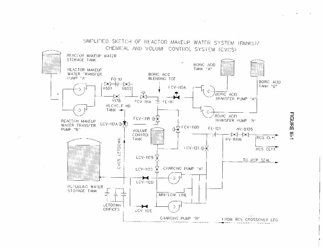
SIMPLIFIED SKETCH OF REACTOR MAKEUP WATER SYSTEM (RMWS)/ CHEMICAL AND VOLUME CONTROL SYSTEM (CVCS)
REACTOR MAKEUP WATER STORAGE TANK
REACTOR MAKEUP WATER TRANSFER PUMP "A" Fn_
RE/ WA PUN
TANK
BORIC ACID TANK "A"
BORIC ACID BLENDING TEE
I FCV-110A
BORIC ACID TANK( "B"
. _ j B O R IC A C ID -n FCV-111B RANSFER PUMP "B") \CTOR MAKEUP TAF , c IER TRANSFER LCV-112A FGV 11 X IP 'B' VOLUME -O FE-121 HV-8105
CONTROL VRCS CL" z TANK HV-8106 RSC,
FCV-121 RCS CL•4
iiii~iiiiii~iii~iiii~iiiiiii~iiiiii • LCV- 112LB Iiiiiii LCVTO RCP SEAL
LCV-112C CHARGING PUMP "A"
--------------------------- -------------
REFUELING WATER /
STORAGE TANK j f -&-_ -7- --_ I I
LETDOWN ORIFICES LCV- 112E
FROM RCS CROSSOVER LEG - - - . -. . . . . . .- . .- . .- . .- . .- . .- . .- . .- . .- ..- . .- . .-
CHARGING PUMP "B"' - - - - - - - - -- - - - - - - - - - - - - - - - - - - - -.
set the blended flow rate and the boric acid flow rate. The makeup controller will then limit the sum of the boric acid flow rate and primary grade water flow rate to the blended flow rate after turning the RMWS makeup control handswitch to the "Run" position (i.e., the controller regulates the unborated, primary grade makeup water flow rate).
An inadvertent boron dilution may be initiated by a failure in the RMWS which results in either a reduction in the boric acid flow rate from the BATs or an increase in the flow rate of unborated water from the Reactor Makeup Water Storage Tank (RMWST).
IV. Description of RMCS Design & Operation
The Reactor Makeup Control System (RMCS), described in FSAR Section 9.3.4.2.1.3, consists of a group of instruments arranged to provide a manually pre-selected makeup concentration of boric acid to the charging pump suction header or the Volume Control Tank (VCT). The RMCS control functions maintain the desired fluid inventory in the VCT and adjust the reactor coolant boron concentration.
Under normal plant operating conditions, the RCS letdown is routed to the VCT. A three-way diversion valve (BGLCV01 12A) is provided which may be used to divert letdown to the Recycle Holdup Tanks (RHTs). Currently, this valve is normally positioned to send letdown flow to the VCT and is operated in the "AUTO" mode (i.e., when VCT level reaches 70% of span, the valve will modulate to divert a certain amount of the letdown flow to the RHTs). The VCT level controller controls the operation of the letdown divert valve when in the "AUTO" mode. For planned plant evolutions performed in accordance with approved procedures, the letdown divert valve may be placed in the manual "RHT" mode. The reactor operator controls the valve position in the manual "RHT" mode. In the "AUTO" or manual "RHT" modes, the operation of the letdown divert valve (by either automatic or manual control) would act to prevent the VCT water level from exceeding the high VCT water level alarm setpoint. Upon loss of air or electric signal, the letdown divert valve fails to the "VCT" position. As discussed in Section X, the operation of BGLCV01 12A will be changed such that it is in the manual "VCT" mode during MODES 3 through 5 to satisfy the analysis assumption of a closed RCS/CVCS system. Letdown flow will be directed to the VCT in these operational MODES, except during operation of this valve under administrative controls for planned evolutions requiring a high level of operator involvement and awareness. These administrative controls will include verification of the boron concentration of the makeup prior to repositioning the divert valve and restoration requirements to return the valve to
-6-
the manual "VCT" mode upon evolution completion.
The control switches required to initiate a boron dilution are located on the main control board. At Callaway Plant, two switches are provided: one mode selector switch for Off/Borate/Manual/Auto/Alternate Dilute/Dilute and one makeup control switch for Stop/Normal/Run.
The manual mode allows for addition of blended flow to the RWST, to the RHTs, to the spent fuel pools, or to some other location via a temporary connection. While in this mode, automatic makeup to the RCS is precluded.
The automatic makeup mode of operation of the RMCS provides a blended boric acid solution, pre-set to approximately the same boron concentration as the RCS. The automatic makeup controller operates on demand signals from the VCT level controller. Under normal plant operating conditions, the mode selector switch is set in the "Auto" position and the boric acid and total makeup flow controllers are set to provide approximately the same concentration of borated water as contained in the RCS. The mode selector switch must be in the "Auto" position and the controller energized by prior manipulation of the makeup control handswitch in the "Run" position. A pre-set low level signal from the VCT level controller causes the automatic makeup control action to start a reactor makeup water pump, start a boric acid transfer pump, open the reactor makeup isolation valve (BGFCV011 0B) to the outlet of the VCT, and position the reactor makeup water and boric acid flow control valves (BGFCV011 1A and BGFCV011 A, respectively). The flow controllers automatically blend the boric acid and reactor makeup water flows to the pre-set concentration.
Makeup addition to the charging pump suction header causes the water level in the VCT to rise. At the pre-set high level setpoint, the reactor makeup water pump stops, the boric acid transfer pump stops, the reactor makeup water and boric acid flow control valves close, and the reactor makeup isolation valve closes. This operation may be terminated manually at any time by placing the makeup control handswitch in the "Stop" position.
The dilute mode of operation permits the addition of a pre-selected quantity of reactor makeup water at a pre-selected flow rate to the RCS. The reactor operator sets the mode selector switch to "Dilute", the total makeup flow controller setpoint to the desired flow rate, the total makeup batch integrator to the desired quantity, and actuates the makeup start switch. The start signal causes the makeup control system to start a reactor makeup water pump, open the reactor makeup isolation valve to the VCT inlet (BGFCV01 11 B), and open the reactor makeup water flow control valve (BGFCV011 1A). The makeup water is injected through the VCT spray nozzle and, subsequently, through the VCT to
-7-
the charging pump suction header. When the pre-set quantity of reactor makeup water has been added, the batch integrator causes the reactor makeup water pump to stop, closes the reactor makeup water flow control valve, and closes the reactor makeup isolation valve. This operation may be terminated manually at any time as discussed above.
The alternate dilute mode of operation is similar to the dilute mode, except a portion of the dilution water flows directly to the charging pump suction (through BGFCV011 0B) and a portion flows into the VCT (through BGFCV01 11 B) before flowing to the charging pump suction. This mode of operation is used when intentionally diluting the RCS in order to minimize the delay caused by diluting the VCT before the RCS can be diluted. When the pre-set quantity of reactor makeup water has been added, the batch integrator stops the reactor makeup water pump, closes the reactor makeup water flow control valve, and closes the reactor makeup isolation valves to the inlet and outlet of the VCT. This operation may be terminated manually at any time as discussed above.
The borate mode of operation permits the addition of a pre-selected quantity of concentrated boric acid solution at a pre-selected flow rate to the RCS. The operator sets the mode selector switch to "borate", the concentrated boric acid flow controller setpoint to the desired flow rate, and the concentrated boric acid batch integrator to the desired quantity, and places the makeup control handswitch in the "Run" position. The concentrated boric acid is added to the charging pump suction header. The total quantity added in most cases would be so small that it will have only a minor effect on the VCT level. When the pre-set quantity of concentrated boric acid solution has been added, the batch integrator causes the makeup to stop. This operation may be manually terminated at any time as discussed above.
V. Detection of an Inadvertent Boron Dilution Event in Modes 3, 4, and 5
The inadvertent boron dilution event is assumed to be initiated through a malfunction in the Reactor Makeup Control System or by operator error. Several indications and alarms are provided in the RMCS design for monitoring proper system operation. The available alarms and indications include:
- boric acid flow indication and deviation alarm; - audible clicks from the boric acid totalizer (flow integrator); - boric acid flow strip chart recorder; - total makeup blended flow indication and deviation alarm;
-8-
audible clicks from the total makeup blended flow totalizer (flow integrator);
- total makeup blended flow strip chart recorder; - high charging flow indication and alarm; - centrifugal charging pump, boric acid transfer pump, and
reactor makeup control system pump status lights; and boron concentration measurement system.
Several potential RMCS failures will result in an increase in the VCT water level and pressure. The available alarms are the high VCT pressure, high VCT water level, and high-high VCT water level/full divert to RHT alarms.
Other diverse indications of an ongoing inadvertent boron dilution event are provided by the Nuclear Instrumentation System. The available indications and alarms when the reactor is subcritical include:
- high source range neutron flux at shutdown alarm; - indicated and recorded source range neutron flux rate count rate and
indicated startup rate; - audible source range neutron flux count rate; and - source range neutron flux-multiplication alarm (to be retained as
discussed in Section X).
VI. Inadvertent Boron Dilution Event Scenarios
The inadvertent boron dilution event is assumed to be initiated by a malfunction in the RMCS. A failure modes and effects analysis is provided below for each of the significant modes of RMCS operation with a focus on those malfunctions which result in either a reduction in the boric acid flow rate from the BATs or an increase in the flow rate of unborated water from the RMWST. It is assumed that the CVCS and RMWS valve positions correspond to their normal alignments.
The scenarios described below are initiated by a postulated malfunction; no additional single failure is assumed.
Potential inadvertent dilutions from sources other than through the RMWS (e.g., via the Boron Thermal Regeneration System or Boron Recycle System) are precluded during normal operations by at least one and usually several closed manual valves. Because operations of these systems are plant evolutions performed in accordance with approved procedures and require a significant level of reactor operator interaction with the plant, these dilution scenarios are not considered further.
-9-
Automatic Operation
In this mode, the reactor operator manually sets the RMCS controller to provide approximately the same concentration of borated water as contained in the RCS. The total makeup flow is initiated by the VCT water level controller when the VCT water level falls below the "start auto makeup" setpoint (see Figure VI-1). The flow is terminated when the VCT water level rises above the "stop auto makeup" setpoint. In this mode of operation, the potential malfunctions which could affect the inadvertent boron dilution event are:
a) Concentrated boric acid flow is less than required. b) Reactor makeup flow is greater than required. c) Due to operator error, calibration errors, or instrument drift, the makeup
water boron concentration is less than the RCS boron concentration. d) Total makeup flow is not terminated at the "stop auto makeup" setpoint.
Individually, potential malfunctions a, b, or c could result in the addition of dilute water into the VCT and, subsequently, the RCS. However, in the absence of an additional failure, the dilution would be limited to the volume of water between the "start auto makeup" and "stop auto makeup" VCT water level setpoints.
A malfunction which results in the continuation of total makeup flow to the VCT after the "stop auto makeup" setpoint has been exceeded would eventually result in a high VCT pressure or high VCT water level alarm. Two redundant high VCT water level alarms set at 70% of span will be added, as shown on Figure VI-1 and as discussed in Section X. In the absence of an additional failure, no dilution would occur because the boron concentration of the makeup would be the same as the RCS boron concentration.
Dilute and Alternate Dilute Operation
In these modes, the reactor operator intentionally injects a pre-selected quantity of reactor makeup water at a pre-selected flow rate to the RCS. These are planned dilutions, performed in accordance with approved plant procedures. The postulated malfunctions of importance to the inadvertent boron dilution event analysis are the malfunction of the RMCS to limit the flow rate of the reactor makeup water or the malfunction of the totalizer (integrator) to terminate the dilution when the requisite amount of reactor makeup water has been added. The proper operation of the totalizer would offset any failure to control the flow rate.
-10-
Borate Operation
In this mode, the reactor operator intentionally injects a pre-selected quantity of concentrated boric acid solution at a pre-selected flow rate to the RCS. There is no blending with reactor makeup water to form a more dilute boric acid solution; hence, there is no possibility for an inadvertent boron dilution event in this mode.
Design Basis Scenario
The design basis scenario for the inadvertent boron dilution event is that scenario which results in a continuous dilution at the highest dilution rate. As may be inferred from the previous discussions, only operation in the automatic and dilute/alternate dilute modes can result in inadvertent boron dilutions. In the scenarios described below, a single failure is assumed in addition to the initiating malfunction.
Because operation in the dilute/alternate dilute modes is, by definition, a planned plant evolution, the reactor operators are expecting a specific response in accordance with their training. It is expected that any malfunctions which occur would be immediately observed, resulting in timely operator action to mitigate the dilution. The CVCS alarms previously described are available for the detection of inadvertent dilutions. In addition, diverse alarms from the Nuclear Instrumentation System are available to assist the reactor operators in the detection of a potential malfunction. Procedural guidance is also provided to the operators concerning methods of terminating unplanned moderator dilutions. Hence, inadvertent dilutions in these modes of operation will not be considered in the development of the design basis scenario.
Any malfunction in the RMCS, while in the automatic mode of operation, coupled with an additional single active failure or single operator error, could result in the continuous injection of nearly pure water into the RCS. In order to bound all combinations of two failures (initiating malfunction plus additional single failure), the design-basis scenario for the inadvertent boron dilution event is defined to be:
1) The plant is initially at steady-state conditions in MODE 3, 4, or 5, with the CVCS and RMWS valves in their normal positions and the letdown divert valve is in the manual "VCT" mode, as discussed in Section X.
2) The initiating malfunction in the RMCS results in the delivery of the maximum amount of reactor makeup water (equal to the maximum charging flow rate alarm) at the lowest boron concentration (0 ppm boron).
-11-
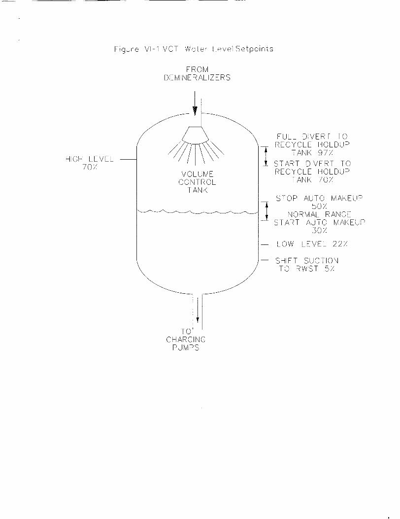
Figure VI-1 VCT Water Level Setpoints
FROMIv D EMI NEFRAL IZ ERS
HIGH LEVEL 70/.
VOLUME CONTROL
TANK
FULL DIVERT TO RECYCLE HOLDUP
TANK 97. START DIVERT TO RECYCLE HOLDUP
TANK 70/
STOP AUTO MAKEUP 50/
NORMAL RANGE START AUTO MAKEUP
30/
LOW LEVEL 22/.
SHIFT SUCTION TO RWST 5/
IU CHARGING
PUMPS
3) A single failure in the VCT level controller results in the continuation of the dilution flow, even after the "stop auto makeup" setpoint is exceeded.
4) High VCT water level provides the first alarm indicating that a boron dilution may be in progress.
5) The reactor operators are allocated 15 minutes to diagnose the event and initiate actions to isolate dilution sources. The operator response time is assumed to extend from the time when the high VCT water level is annunciated (currently 97% of span, but will be changed to 70% of span as discussed in Section X) until the operator initiates corrective actions.
VII. Equipment Design
The inadvertent boron dilution event in Modes 3, 4, and 5 is an ANS Condition II event. As a result of this event, no automatic Reactor Trip System or Engineered Safety Features Actuation System actuations are required for event detection, termination, or mitigation. No adverse containment environments are generated.
The normal charging and letdown portions of the CVCS, as well as the RMCS, are "control grade" systems. The power supplies for the level, pressure, and flow instrumentation are derived from Class 1 E inverters. With the exception of the new high VCT water level alarms to be added to instrument loops BGL-01 12 and BGL-0185, none of the CVCS/RMCS alarms previously mentioned are redundant. All transmitters associated with the CVCS and RMCS are subjected to periodic calibrations.
The valves required for termination of the dilution and the centrifugal charging pumps are powered from Class 1 E power supplies.
VIII. Method of Analysis
Calculations have determined the time required to move water at known flow rates to dilute known masses of water and to fill known volumes. Variations in the flow rates over time are averaged into constant values. Changes in the water level in the VCT will generate alarms when setpoints are exceeded. Maximum or minimum values are assumed for flows, volumes, and boron concentrations, as appropriate, to effectively bound the most conservative average values. The analysis is performed over the entire range of RCS temperatures in MODES 3-5
-13-
(from 5570F to 680F) in order to ensure that the most conservative combinations of RCS coolant density, initial and critical boron concentrations, and shutdown margin are evaluated. The results of this analysis demonstrate that at least 15 minutes is available for the reactor operator to initiate corrective actions in order to prevent the complete loss of shutdown margin (i.e., criticality) from the time the high VCT water level alarm is generated.
RCS leakage and control system anomalies can affect the volume of water in the RCS and in the CVCS. This analysis conservatively bounds those effects by assigning a bounding steady-state mismatch value to the flows which affect the VCT water level.
Model Limitations and Assumptions
1) The RCS volume remains constant. The water level in the pressurizer does not change. Reactor operators set charging and letdown to maintain a constant system volume during steady state operations if automatic systems are not available. Small deviations of RCS mass during the dilution event can result from charging and letdown flow mismatches. A flow mismatch term is included to account for these small deviations.
2) The RCS and CVCS are configured to form a closed system. Dilution water may enter the system boundary, but no water leaves the boundary during steady state operations. The small values of RCS leakage are accommodated by the flow mismatch term. All changes to the system volume are assigned to the VCT. Any addition of water to the RCS results in a change in VCT volume without changing the volume of water in any other system.
3) All dilutions occur at a constant rate. The RCS dilution is modeled as a step change from zero gpm to a constant dilution rate. The maximum dilution rate is considered.
4) The Net Operator Response Time (the actual time available for the reactor operator to respond before the shutdown margin is completely lost) begins only after the high VCT water level alarm is reached, and it ends at the time when operator action would no longer prevent criticality. System delays for filling the VCT to the high level alarm setpoint, valve manipulations, and purging diluted pipes with boric acid reduce the Net Operator Response Time.
-14-
5) The subsystem temperatures are selected in such a way as to minimize the available mixing mass and maximize the dilution mass flow rate. The RCS mass is evaluated at operating MODE temperature boundaries, i.e., 557°F, 350°F, 200 0F, and 680F. The CVCS/RMWS fluid is evaluated at 37 0F. Maximizing the density of the CVCS/RMWS and minimizing the density of the RCS act to increase the dilution rate.
6) The RCS temperature remains constant. The small fluctuations in RCS temperature during steady-state operations are accommodated with the flow mismatch term.
7) The reactor is shutdown and the initial boron concentration is sufficient to meet the minimum shutdown margin required for each particular mode of operation, in accordance with the core operating limits report (COLR).
8) It is assumed that the most reactive rod is stuck out of the core.
9) A conservatively low value for the RCS volume is assumed. This volume corresponds to the active volume of the RCS. For the analysis of the inadvertent boron dilution event, Westinghouse determined that the active volume, including the coolant in the vessel, the RCS loops, and the steam generator tubes (minus 10% for tube plugging) can be considered to be actively mixed as long as at least one RCS loop is in operation. This active volume does not credit any volume in the reactor vessel upper head, the pressurizer, the pressurizer spray and surge lines, the CVCS, and the Residual Heat Removal System. One reactor coolant pump can provide sufficient driving force to ensure adequate mixing of all four reactor coolant loops. The volumes are based on cold metal dimensions, with no allowance for thermal expansion of the volumes.
10) All times in core lifetime are considered. Generally, beginning of life (BOL) is limiting due to the higher boron concentrations which maximize the dilution worth.
As described in Section VI, the design basis inadvertent boron dilution event is assumed to be initiated from steady-state conditions in MODE 3, 4, or 5 with all CVCS and RMWS valves in their normal positions (subject to the changes discussed in Section X) for the shutdown modes of operation. In this state, all letdown is returned to the VCT. The event is assumed to be initiated when the RMCS initiates auto makeup, based on the VCT water level at the "start auto makeup" setpoint. The initiating event is assumed to be a malfunction in the
-15-
RMCS which results in the delivery of diluted (0 ppm boron) water to the charging pump suction. This dilute fluid is then injected into the RCS through the normal charging flow path. An additional failure in the VCT water level controller is assumed such that the dilution continues after the VCT water level has risen above the "stop auto makeup" setpoint.
Even though it is likely other alarm functions will have annunciated, it is assumed that the reactor operator is first made aware of the RMCS malfunction when the high VCT water level alarm annunciates. To terminate the event, the reactor operator must isolate the dilution source from the VCT. In order to minimize the "Net Operator Response Time," the operators are assumed to fully open the RWST isolation valves, then fully close the VCT isolation valves. This is how these valves are interlocked to operate for an automatic swap-over, as shown on FSAR Figure 7.6-5. If the RWST is unavailable in MODE 5, reboration will occur via the BATs. In either reboration flow path, the diluted water in the CVCS lines must be purged before the borated water from the RWST or the BATs (MODE 5) enters the RCS, terminating the event. In the analysis of this event, it must be demonstrated that following receipt of the high VCT water level alarm, the reactor operator has at least 15 minutes in which to isolate the dilution source prior to the time that the shutdown margin is completely lost (i.e., prior to criticality). As discussed above, the actual time available for reactor operator response is referred to as the "Net Operator Response Time."
Variables
All variables used in the calculations are defined in Table VIII-1. Variables are defined in three types:
(1) Input - a physical parameter fixed by the operating characteristics of the plant;
(2) Property - determined from steam tables; and
(3) Calc - a calculation result determined by algebraic combinations of the inputs and properties.
A "conservative direction" has been assigned to the inputs. The conservative direction minimizes the time between the alarm annunciation and the loss of shutdown margin. This assumption, in turn, minimizes the available time for operator action between the alarm annunciation and the loss of shutdown margin. All other conservative directions are selected based on how the time interval available for operator action is affected. Since all properties are extracted directly from the 1967 ASME steam tables, no conservative direction is applied.
-16-
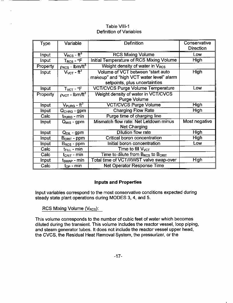
Table VIII-1 Definition of Variables
Type Variable Definition Conservative I Direction
Input VRcS - ft6 RCS Mixing Volume Low Input TRCS - OF Initial Temperature of RCS Mixing Volume High
Property PRCS - Ibm/ftO Weight density of water in VRCS
Input VvcT - ft' Volume of VCT between "start auto High makeup" and "high VCT water level" alarm
setpoints, plus uncertainties Input TVCT - OF VCT/CVCS Purge Volume Temperature Low
Property PvCT - Ibm/ft3 Weight density of water in VCT/CVCS Purge Volume
Input VPURG - ft' VCT/CVCS Purge Volume High Input QCHRG - gpm Charging Flow Rate High Calc tPURG - min Purge time of charging line Input QMIS - gpm Mismatch flow rate: Net Letdown minus Most negative
Net Charging Input QDIL - gpm Dilution flow rate High Input BCRIT - ppm Critical boron concentration High Input BRCS - ppm Initial boron concentration Low Calc tFILL - min Time to fill VVCT
Calc tCRIT - min Time to dilute from BRCS to BCRIT Input tSWAp - min Total time of VCT/RWST valve swap-over High Calc top - min Net Operator Response Time
Inputs and Properties
Input variables correspond to the most conservative conditions expected during steady state plant operations during MODES 3, 4, and 5.
RCS Mixing Volume (VRCS):
This volume corresponds to the number of cubic feet of water which becomes diluted during the transient. This volume includes the reactor vessel, loop piping, and steam generator tubes. It does not include the reactor vessel upper head, the CVCS, the Residual Heat Removal System, the pressurizer, or the
-17-
pressurizer spray and surge lines. The volumes are based on cold metal dimensions, i.e., the thermal expansion at elevated temperatures is neglected. An allowance for plugging of 10% of the steam generator tubes is provided. The entire volume of the RCS can be included if at least one reactor coolant loop is in operation.
Initial Temperature of the RCS Mixing Volume (TRcs):
This temperature is used to determine the density and mass in the RCS mixing volume, VRCS. The temperature is dependent on the specific operational mode under consideration.
Weight Density of Water in VRcs (PRCS):
This parameter is the weight density of saturated water at TRCS. The temperature is dependent on the specific operational mode under consideration. A smaller RCS mass (corresponding to a lower density) is conservative with respect to the rate of dilution.
Volume of VCT between "Start Auto Makeup" and "High VCT Water Level" Setpoints (VvcT):
This parameter is the number of cubic feet of water required to actuate a high VCT water level alarm assuming the transient begins from just below the "start auto makeup" setpoint. Uncertainty allowances of ±5% of span are provided, thereby increasing the total difference in the setpoints by 10% span.
VCT/CVCS Purge Volume Temperature (TvcT):
This parameter is the temperature of the water in the purge volume and is used to determine the density and mass of the purge fluid. In order to maximize the dilution, the temperature is set to the conservatively low value of 37 0F. This temperature is also assumed for the VCT and the letdown. This water volume is assumed to be at saturated conditions. Lower temperatures are not expected during normal operations.
Weight Density of Water in VCT/CVCS Purge Volume:
-18-
This parameter is the weight density of saturated water at TvCT.
VCT/CVCS Purge Volume (VpURG):
This parameter corresponds to the number of cubic feet of diluted water which must be purged from the charging system piping before the borated water from the RWST or the BATs (MODE 5) reaches the RCS cold legs. This volume is required to extend from the check valve downstream of the RWST isolation valves to the injection point of the charging flow into the RCS. The required MODE 3 and 4 purge volume includes the flow path from check valve BG8546A (FSAR Figure 9.3-8 sheet 3, grid point C-7), to the NCP (PBG04), and to the RCS via seal injection and via the regenerative heat exchanger and valve BGHV8147 (FSAR Figure 9.3-8 sheet 1, grid point F-7). The required MODE 5 purge volume includes the flow path from emergency borate valve BGHV8104 (FSAR Figure 9.3-8 sheet 5, grid point A-3), to CCP B (FSAR Figure 9.3-8 sheet 3, grid point D-8), to the normal charging header, and to the RCS via seal injection and via the boron injection header (FSAR Figure 6.3-1 sheet 3, grid point A-8). The MODE 5 purge volume represents the maximum flow path volume that could be used for reboration. Because the effect of the purge volume is to delay the transient's termination, it is conservative to use the maximum purge volume for a particular plant condition. For this calculation, the MODE 5 purge volume of 95 ft3 will be used for all MODES.
Charging Flow Rate (QCHRG):
This parameter is set equal to the sum of the seal injection and normal charging flow rates. All of the charging flow is assumed to enter the RCS mixing volume. This flow rate is assumed to be 150 gpm, a conservatively high value considering that the maximum letdown flow rate is 120 gpm and with consideration given to the high charging flow alarm bistable (BGFBO121A) which is set at 150 gpm. There is no need to close valve BGV0178, as currently reflected in Technical Specification 3.3.9, to support this calculation as discussed under the dilution flow rate section below.
Mismatch Flow Rate (QMIs):
This term is used to account for the effects which would invalidate the constant RCS volume or mass assumption. Small control system fluctuations or temperature changes could result in a mismatch between the charging and letdown flow rates, and small RCS leaks could also increase the need for charging. Because these mismatches could affect the VCT level, it is necessary to explicitly account for them. QMIS is defined by:
QMIS = Letdown (gpm) - Charging (gpm)
-19-
The value of QMIS will conservatively be set to -12 gpm. The -12 gpm penalty is based on 10 gpm for identified leakage, 1 gpm for unidentified leakage, and 1 gpm for primary to secondary leakage (i.e., the limits of Technical Specification LCO 3.4.13). A negative value of QMIS will result in a decreasing VCT water level, which would act to delay the high VCT water level alarm expected if dilution flow were filling the VCT.
Dilution Flow Rate (QDIL):
This parameter is the rate at which water flows into the charging pump suction from a diluted water source. The most limiting value of QDIL is always less than or equal to the charging flow rate. If QDIL is greater than the charging flow rate, then the VCT water level would rise faster without resulting in a more rapid RCS dilution. The RCS dilution rate is limited by the value of the charging flow rate,
QCHRG. For this reason, QDIL must always be less than or equal to QCHRG. A larger dilution rate is conservative; hence, QDIL will be assumed to be equal to QCHRG.
Critical Boron Concentration (BcRIT):
The critical boron concentration represents the maximum boron concentration at which the reactor will attain criticality. The value of this parameter is calculated on a cycle-specific basis. A conservative value is established based upon the core conditions corresponding to the following: critical; zero power; all rods inserted (ARI) except for the most reactive rod which is assumed to be fully withdrawn (ARI, N-1 condition). These values are calculated at 5570F, 3500 F, 2000F, and 680F. The highest value over the cycle life is used. Uncertainties associated with the critical boron calculation are applied in accordance with the shutdown margin calculational methodology. Cycle 11 values are reflected in Table IX-I.
Initial RCS Boron Concentration (BRcs):
The initial boron concentration represents a minimum concentration to maintain the reactor subcritical by the COLR SDM requirements. The value of this parameter is calculated on a cycle-specific basis. The core conditions correspond to the ARI, N-1 condition which just meets the Technical Specification shutdown margin value for a particular operational mode. These values are calculated at 5570 F, 350 0F, 200 0F, and 680F. The time in cycle life is consistent with the BCRIT calculation. Uncertainties associated with the initial critical boron calculation are applied in accordance with the shutdown margin calculational methodology. Cycle 11 values are reflected in Table IX-I.
-20-
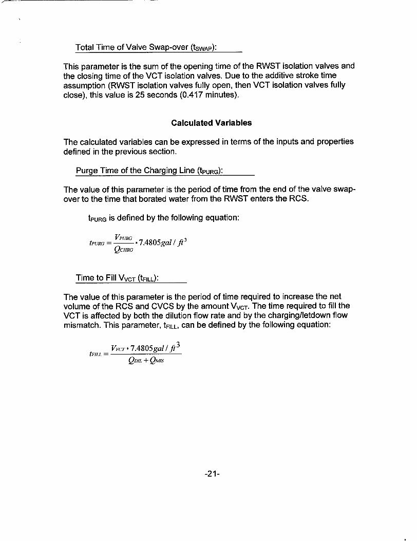
Total Time of Valve Swap-over (tswAp):
This parameter is the sum of the opening time of the RWST isolation valves and the closing time of the VCT isolation valves. Due to the additive stroke time assumption (RWST isolation valves fully open, then VCT isolation valves fully close), this value is 25 seconds (0.417 minutes).
Calculated Variables
The calculated variables can be expressed in terms of the inputs and properties
defined in the previous section.
Purge Time of the Charging Line (tPURG):
The value of this parameter is the period of time from the end of the valve swapover to the time that borated water from the RWST enters the RCS.
tPURG is defined by the following equation:
VPURG tPURG = -- * 7.4805gal/ft3
QCHRG
Time to Fill VVCT (tFILL):
The value of this parameter is the period of time required to increase the net volume of the RCS and CVCS by the amount VVCT. The time required to fill the VCT is affected by both the dilution flow rate and by the charging/letdown flow mismatch. This parameter, tFILL, can be defined by the following equation:
VVCT * 7.4805gal / ft 3
tFILL = QDJL + QMs
-21-
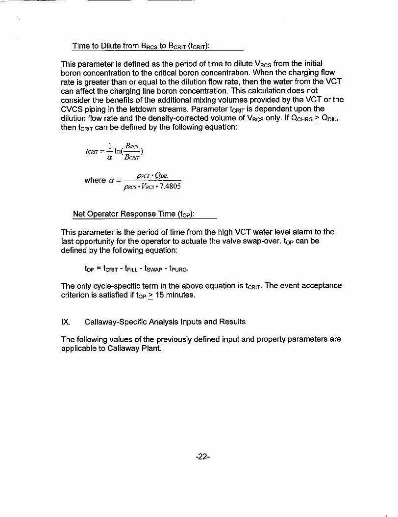
Time to Dilute from BRCS to BCRIT (tCRIT):
This parameter is defined as the period of time to dilute VRCS from the initial boron concentration to the critical boron concentration. When the charging flow rate is greater than or equal to the dilution flow rate, then the water from the VCT can affect the charging line boron concentration. This calculation does not consider the benefits of the additional mixing volumes provided by the VCT or the CVCS piping in the letdown streams. Parameter tCRIT is dependent upon the dilution flow rate and the density-corrected volume of VRCS only. If QCHRG > QDIL,
then tCRIT can be defined by the following equation:
tcmT = 1 In( BRcs
a BCRIT
where a = /VCT - QDJL
pRcs * VRcs * 7.4805
Net Operator Response Time (top):
This parameter is the period of time from the high VCT water level alarm to the last opportunity for the operator to actuate the valve swap-over. top can be defined by the following equation:
top = tCRIT - tFILL - tSWAP - tPURG.
The only cycle-specific term in the above equation is tCRIT. The event acceptance criterion is satisfied if top > 15 minutes.
IX. Callaway-Specific Analysis Inputs and Results
The following values of the previously defined input and property parameters are applicable to Callaway Plant.
-22-
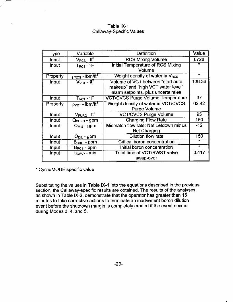
Table IX-1 Callaway-Specific Values
Type Variable Definition Value
Input VRCS - ft' RCS Mixing Volume 8728 Input TRCS - IF Initial Temperature of RCS Mixing *
Volume Property PRCS - Ibm/ft3 Weight density of water in VRcs *
Input VVCT - ft' Volume of VCT between "start auto 136.36 makeup" and "high VCT water level" alarm setpoints, plus uncertainties
Input TVCT - OF VCT/CVCS Purge Volume Temperature 37 Property PVCT - Ibm/ft3 Weight density of water in VCTICVCS 62.42
Purge Volume Input VPURG - ftW VCT/CVCS Purge Volume 95 Input QCHRG - gpm Charging Flow Rate 150 Input QMIS - gpm Mismatch flow rate: Net Letdown minus -12
Net Charging Input QDIL - gpm Dilution flow rate 150 Input BCRIT - ppm Critical boron concentration *
Input BRCS - ppm Initial boron concentration *
Input tSWAP - min Total time of VCT/RWST valve 0.417 swap-over
* Cycle/MODE specific value
Substituting the values in Table IX-1 into the equations described in the previous section, the Callaway-specific results are obtained. The results of the analyses, as shown in Table IX-2, demonstrate that the operator has greater than 15 minutes to take corrective actions to terminate an inadvertent boron dilution event before the shutdown margin is completely eroded if the event occurs during Modes 3, 4, and 5.
-23-
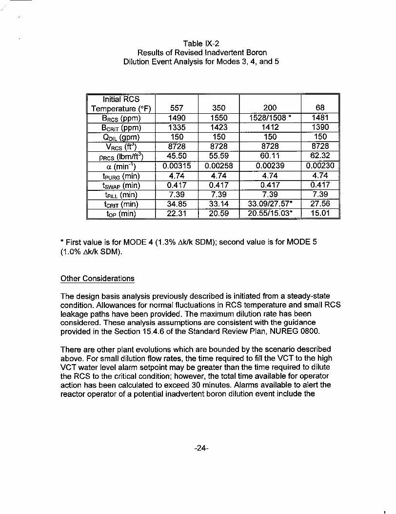
Table IX-2 Results of Revised Inadvertent Boron
Dilution Event Analysis for Modes 3, 4, and 5
Initial RCS Temperature (OF) 557 350 200 68
BRCS (ppm) 1490 1550 1528/1508* 1481 BCRIT (ppm) 1335 1423 1412 1390
QDIL (gpm) 150 150 150 150 VRCS (ftW) 8728 8728 8728 8728
PRCS (Ibm/ft3) 45.50 55.59 60.11 62.32 cc (min-1 ) 0.00315 0.00258 0.00239 0.00230
tPURG (min) 4.74 4.74 4.74 4.74 tSWAP (min) 0.417 0.417 0.417 0.417 tFILL (min) 7.39 7.39 7.39 7.39 tCRIT (min) 34.85 33.14 33.09/27.57* 27.56 top (min) 22.31 20.59 20.55/15.03* 15.01
* First value is for MODE 4 (1.0% Ak/k SDM).
(1.3% Ak/k SDM); second value is for MODE 5
Other Considerations
The design basis analysis previously described is initiated from a steady-state condition. Allowances for normal fluctuations in RCS temperature and small RCS leakage paths have been provided. The maximum dilution rate has been considered. These analysis assumptions are consistent with the guidance provided in the Section 15.4.6 of the Standard Review Plan, NUREG 0800.
There are other plant evolutions which are bounded by the scenario described above. For small dilution flow rates, the time required to fill the VCT to the high VCT water level alarm setpoint may be greater than the time required to dilute the RCS to the critical condition; however, the total time available for operator action has been calculated to exceed 30 minutes. Alarms available to alert the reactor operator of a potential inadvertent boron dilution event include the
-24-
concentrated boric acid flow and total makeup flow deviation alarms. The alarms generated by the Nuclear Instrumentation System, or the available trend recorders, may be of more use to aid the reactor operators in the identification of an inadvertent boron dilution event for these slow dilution cases. Off-normal procedure OTO-ZZ-00003, "Loss of Shutdown Margin," was revised to reflect the slow dilution analysis.
During planned transients, such as plant heatups and cooldowns, the CVCS and RMWS may not be in their normal alignments. However, these evolutions are transitions between stable plant states and are performed in accordance with approved procedures. Strict administrative controls are in place which require significant operator interaction with the plant. In accordance with their training, the reactor operators are expecting specific responses during the evolutions and deviations from the norm receive additional attention. The added alarms will further increase operator awareness.
During a plant heatup, water from the RCS is expelled from the closed RCS/CVCS system into the Recycle Holdup Tanks. The dilution sources are typically isolated during this mode of operation in order to minimize the liquid radwaste processing above the letdown flow already being diverted to the RHTs. If, through operator error, a dilution mechanism was introduced, the letdown divert valve would not be in the manual "VCT" mode; hence, the high VCT water level alarm function is not an appropriate alarm for use in the detection of an inadvertent boron dilution event in this scenario. However, the total makeup flow and concentrated boric acid flow rate deviation alarms remain useful, and the Nuclear Instrumentation System continues to provide diverse alarms and indications of inadvertent reactivity changes.
Prior to performance of a plant cooldown, the RCS is borated to that concentration required to maintain the shutdown concentration at the target temperature. During the cooldown itself, the mismatch between the charging and letdown flow rates is fairly large, as additional fluid is injected into the RCS to compensate for shrinkage. This exceptionally large, mismatch between the charging and letdown flow rates may be sufficient to mask certain indications of an inadvertent boron dilution. However, the total makeup flow and concentrated boric acid flow rate deviation alarms remain useful, and the Nuclear Instrumentation System continues to provide diverse alarms and indications of inadvertent reactivity changes. In addition, cooldowns are performed with the reactor trip breakers open; hence, the assumption that the most reactive rod is withdrawn from the core is not necessary. Consideration of this assumption alone is sufficient to compensate for all cooldown scenarios allowed within the context of the plant Technical Specifications.
-25-
X. Callaway-Specific Actions Required for Implementation
The revised analytical methodology for the inadvertent boron dilution event is based on the premise that certain plant-specific activities will be completed. These activities are:
Installation of an alarm on the letdown divert valve (BGLCV01 12A) which will annunciate when the valve is not in the "VCT" position. In MODES 1 and 2, the valve will normally be operated in the "AUTO" mode with the valve positioned to send letdown flow to the VCT. Prior to entering MODE 3 from MODE 2 during a plant shutdown and prior to entering MODE 5 from MODE 6 during a plant startup, the valve will be placed in the manual 'CT" mode. Therefore, the annunciator window will be dark during MODES 3 through 5, except when the valve is operated under administrative controls during planned evolutions requiring a high degree of operator involvement and awareness. These administrative controls will include verification of the boron concentration of the makeup prior to repositioning the divert valve and restoration requirements to return the valve to the manual "VCT" mode upon evolution completion.
Installation of two redundant alarms for high VCT water level on safetyrelated instrument loops BGL-01 12 and BGL-0185. The setpoint for this function (70% of span) is credited in the analysis. This setpoint is lower than the current high VCT water level alarm setpoint on the non-safety instrument loop (BGLB0149A is set at 97% of span and will only be associated with the full divert to RHT alarm after modification completion) and greater than the "stop auto makeup" setpoint (50% of span).
Revisions to operating procedures to heighten operator awareness during evolutions that may potentially impact boron concentration and to include the new CVCS alarms and indications for timely event recognition as well as the necessary actions for event termination.
FSAR Chapter 16 changes will be implemented which will require the isolation of the dilution source valves unless at least one reactor coolant loop is in operation and one high VCT water level alarm is operable in MODES 3-5.
The source range flux multiplication alarm will be retained at its current setpoint; however, the automatic valve swap-over function will be eliminated.
-26-
Xl. Summary
The current analysis of the inadvertent boron dilution event for Modes 3, 4, and 5, as described in FSAR Section 15.4.6, is based on the operation of the Boron Dilution Mitigation System. In the time since that analysis was performed, a revised analytical methodology for the inadvertent boron dilution event has been developed.
With this revised method it is recognized that the Chemical and Volume Control System and the Reactor Coolant System can be configured to form a closed system, and mass imbalances which affect the RCS may be detected in the CVCS. Numerous alarm functions in the CVCS have been identified which will provide indication to the reactor operators of a potential inadvertent boron dilution event. The Nuclear Instrumentation System also provides several diverse alarms to assist the reactor operators in the detection of such an event.
Using the revised analysis methodology, an analysis of the event has been performed for Callaway Plant's current Cycle 11. Compliance with event-specific acceptance criteria, selected to be consistent with the guidance of the Standard Review Plan, has been demonstrated for this core configuration. As is currently the case, each reload safety evaluation will verify that the acceptance criteria continue to be met.
-27-