Ae105 Final Presentation - California Institute of...
159
Ae105 Final Presentation AAReST: Autonomous Assembly of a Reconfigurable Space Telescope 1 June 2015
Transcript of Ae105 Final Presentation - California Institute of...

Ae105 Final Presentation
AAReST:Autonomous Assembly of a Reconfigurable Space Telescope
1 June 2015

AAReST Mission Overview
Manan Arya

Building Large Space Telescopes
Ae105 Final Presentation 3
• Mirror dia. of current and planned
space telescopes limited by constraints
of a single launch
– Hubble (1990): Ø 2.4 m
– JWST (2018): Ø 6.5 m
– ATLAST (2020+): Ø 8-16 m
• New paradigms needed for Ø 30 m+
segmented primary:
– Autonomous assembly in orbit
– Active ultralight mirror segments
• Active mirrors relax tolerances for
assembly and manufacturing, correct
thermal distortions
• Modular, robust, low-cost architecture

AAReST Objectives
• Demonstrate key technologies:
– Autonomous assembly and reconfiguration of modular
spacecraft carrying mirror segments
– Active, lightweight deformable mirrors operating as segments in
a primary
• Operate for as long as necessary to accomplish the
objectives (~90 days)
• Gather engineering data to enable development of the
next system
Ae105 Final Presentation 4


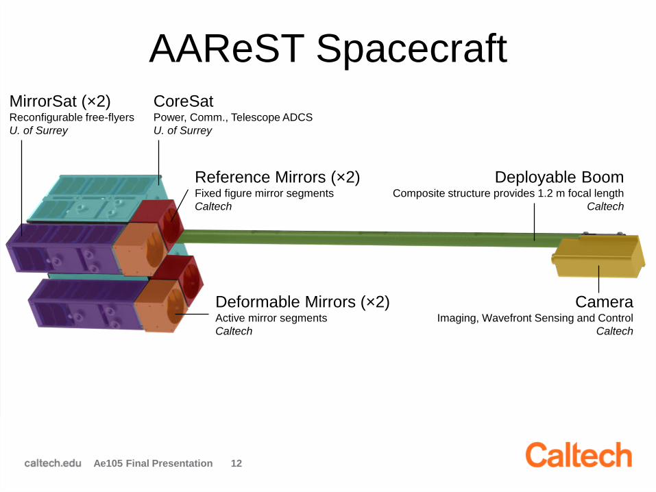
AAReST Spacecraft
Ae105 Final Presentation 6

AAReST Spacecraft
Ae105 Final Presentation 7
CoreSatPower, Comm., Telescope ADCS
U. of Surrey

AAReST Spacecraft
Ae105 Final Presentation 8
CoreSatPower, Comm., Telescope ADCS
U. of Surrey
MirrorSat (×2)Reconfigurable free-flyers
U. of Surrey

AAReST Spacecraft
Ae105 Final Presentation 9
CoreSatPower, Comm., Telescope ADCS
U. of Surrey
MirrorSat (×2)Reconfigurable free-flyers
U. of Surrey
Deformable Mirrors (×2)Active mirror segments
Caltech

AAReST Spacecraft
Ae105 Final Presentation 10
CoreSatPower, Comm., Telescope ADCS
U. of Surrey
MirrorSat (×2)Reconfigurable free-flyers
U. of Surrey
Deformable Mirrors (×2)Active mirror segments
Caltech
Reference Mirrors (×2)Fixed figure mirror segments
Caltech

AAReST Spacecraft
Ae105 Final Presentation 11
CoreSatPower, Comm., Telescope ADCS
U. of Surrey
MirrorSat (×2)Reconfigurable free-flyers
U. of Surrey
Deformable Mirrors (×2)Active mirror segments
Caltech
Deployable BoomComposite structure provides 1.2 m focal length
Caltech
Reference Mirrors (×2)Fixed figure mirror segments
Caltech
AAReST Spacecraft
Ae105 Final Presentation 12
CoreSatPower, Comm., Telescope ADCS
U. of Surrey
MirrorSat (×2)Reconfigurable free-flyers
U. of Surrey
Deformable Mirrors (×2)Active mirror segments
Caltech
Deployable BoomComposite structure provides 1.2 m focal length
Caltech
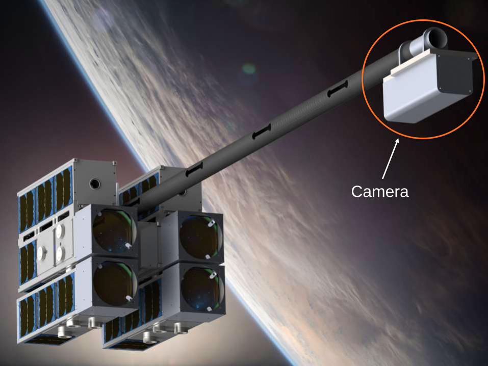
CameraImaging, Wavefront Sensing and Control
Caltech
Reference Mirrors (×2)Fixed figure mirror segments
Caltech

AAReST Spacecraft
Ae105 Final Presentation 13
CoreSatPower, Comm., Telescope ADCS
U. of Surrey
MirrorSat (×2)Reconfigurable free-flyers
U. of Surrey
Deformable Mirrors (×2)Active mirror segments
Caltech
Deployable BoomComposite structure provides 1.2 m focal length
Caltech
CameraImaging, Wavefront Sensing and Control
Caltech
Reference Mirrors (×2)Fixed figure mirror segments
Caltech
Mass: <40 kg
CoreSat: 20 × 30 × 35 cm
MirrorSat: 10 × 10 × 30 cm
Boom: Ø 38 mm,1.5 m long
Prime focus telescope
465 nm – 615 nm bandpass
0.3 deg. field of view
1.2 m focal length
UHF down (9600 bps)
VHF up (1200 bps)
S-Band ISL
Ref. orbits:
~650 km SSO
ISS (400 km,
52 deg. incl.)

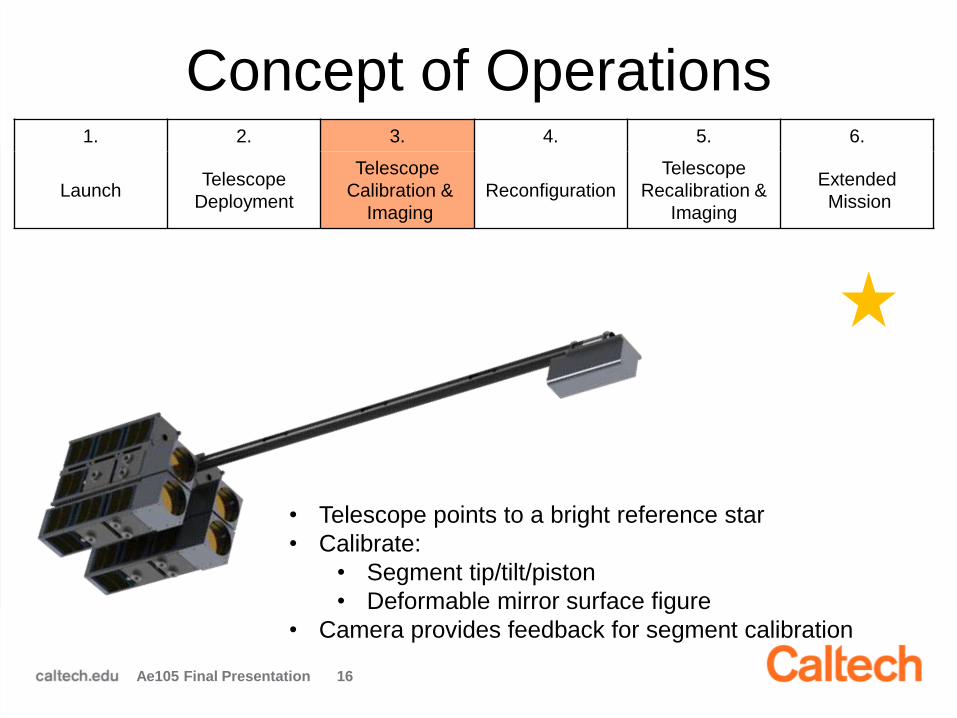
Concept of Operations
Ae105 Final Presentation 14
1. 2. 3. 4. 5. 6.
LaunchTelescope
Deployment
Telescope
Calibration &
Imaging
Reconfiguration
Telescope
Recalibration &
Imaging
Extended
Mission
Launch in a compact, stowed volume
• 30 cm × 35 cm × 45 cm

Concept of Operations
Ae105 Final Presentation 15
• Turn on, verify satellite components
• Stabilize attitude, temperature
1. 2. 3. 4. 5. 6.
LaunchTelescope
Deployment
Telescope
Calibration &
Imaging
Reconfiguration
Telescope
Recalibration &
Imaging
Extended
Mission
• Deploy boom in two stages:
1. Boom segments unfold
2. Camera is released
• Uncage deformable mirrors
Concept of Operations
Ae105 Final Presentation 16
• Telescope points to a bright reference star
• Calibrate:
• Segment tip/tilt/piston
• Deformable mirror surface figure
• Camera provides feedback for segment calibration
1. 2. 3. 4. 5. 6.
LaunchTelescope
Deployment
Telescope
Calibration &
Imaging
Reconfiguration
Telescope
Recalibration &
Imaging
Extended
Mission

Concept of Operations
Ae105 Final Presentation 17
• MirrorSats release from CoreSat (one at a time)
• Fly out ~1 m
• Re-dock into “wide” configuration
1. 2. 3. 4. 5. 6.
LaunchTelescope
Deployment
Telescope
Calibration &
Imaging
Reconfiguration
Telescope
Recalibration &
Imaging
Extended
Mission

Concept of Operations
Ae105 Final Presentation 18
• Telescope points to a bright reference star
• Calibrate:
• Segment tip/tilt/piston
• Deformable mirror surface figure
• Camera provides feedback for segment calibration
1. 2. 3. 4. 5. 6.
LaunchTelescope
Deployment
Telescope
Calibration &
Imaging
Reconfiguration
Telescope
Recalibration &
Imaging
Extended
Mission

Concept of Operations
Ae105 Final Presentation 19
1. 2. 3. 4. 5. 6.
LaunchTelescope
Deployment
Telescope
Calibration &
Imaging
Reconfiguration
Telescope
Recalibration &
Imaging
Extended
Mission
• Co-align star images from different segments to improve SNR
– Pre-cursor to co-phasing
• Produce images of extended sources (e.g. Moon, Earth) for outreach

AAReST Optical Overview
Ae105 Final Presentation 21
M1 focal length: 1.163 m
Ø 0.405 m aperture
(narrow), f/D = 2.87
Ø 0.530 m aperture
(wide), f/D = 2.19
Primary Mirror (M1)
Camera
Ø 0.100 m segments,
masked to Ø 0.090 m
• Full Field of View : 0.3°
• Optical bandwidth: 465-615 nm (540 nm center)
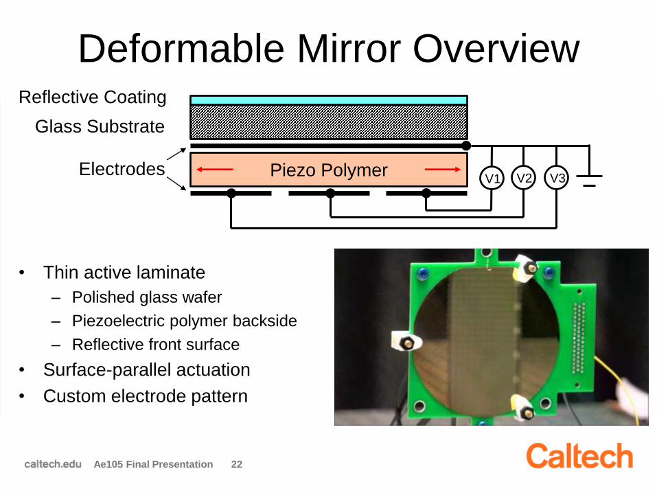
Deformable Mirror Overview
Ae105 Final Presentation 22
• Thin active laminate
– Polished glass wafer
– Piezoelectric polymer backside
– Reflective front surface
• Surface-parallel actuation
• Custom electrode pattern
Piezo Polymer
Glass Substrate
Electrodes
Reflective Coating
V1 V2 V3
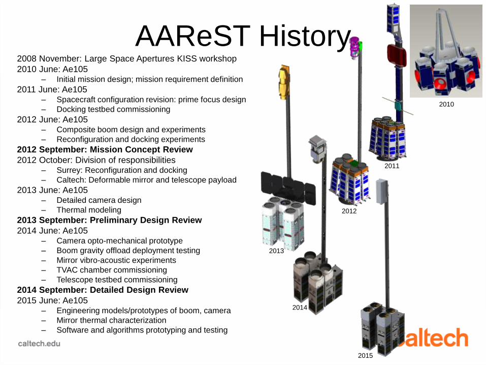
2008 November: Large Space Apertures KISS workshop
2010 June: Ae105– Initial mission design; mission requirement definition
2011 June: Ae105– Spacecraft configuration revision: prime focus design
– Docking testbed commissioning
2012 June: Ae105 – Composite boom design and experiments
– Reconfiguration and docking experiments
2012 September: Mission Concept Review
2012 October: Division of responsibilities– Surrey: Reconfiguration and docking
– Caltech: Deformable mirror and telescope payload
2013 June: Ae105– Detailed camera design
– Thermal modeling
2013 September: Preliminary Design Review
2014 June: Ae105– Camera opto-mechanical prototype
– Boom gravity offload deployment testing
– Mirror vibro-acoustic experiments
– TVAC chamber commissioning
– Telescope testbed commissioning
2014 September: Detailed Design Review
2015 June: Ae105– Engineering models/prototypes of boom, camera
– Mirror thermal characterization
– Software and algorithms prototyping and testing
AAReST History
2010
2011
2012
2013
2014
2015

2014 Ae105 Accomplishments
Ae105 Final Presentation 25
Telescope Testbed Commissioning
• Full-scale telescope testbed
• Autocollimation to simulate incoming starlight
• To test mirror + camera hardware, and
calibration software

2014 Ae105 Accomplishments
Ae105 Final Presentation 26
TVAC Chamber Commissioning
• Need deformable mirrors to be
thermally balanced
• Built a TVAC chamber to study
mirror thermal deformations
• Optical window allows mirror figure
to be measured at all times

2014 Ae105 Accomplishments
Ae105 Final Presentation 27
Boom Stage 2 Gravity Offload Testing

Presentation Outline1. Boom Subsystem Validation
– Stage 1 deployment testing & long-term storage effects
2. Mirror Thermal Deformation Testing
– Designing a thermally balanced mirror segments
3. Mirror Box Mechanical Design
– Designing mirror mounting and launch restraint systems
4. Camera Prototyping
– Opto-mechanical prototype manufacturing and testing
5. Mirror Calibration Algorithms
– Mirror segment search, pointing, and surface figure control
6. On-Board Software
– Telescope software architecture design and implmentation
– 15 min. presentations + 5 min. discussion
Ae105 Final Presentation 28

Boom Subsystem Validation
Serena Ferraro
Christophe Leclerc
Kirsti Pajunen
Mentor: Arturo Mateos

Boom

Boom Subsystem Overview
Purpose:
• Guarantee successful deployment of the composite boom
• Ensure alignment of optical systems after deployment
Team Responsibilities:
• Evaluate deployment sequence
• Design and test boom and boom-CoreSat interfaces
• Currently in verification
and validation phase
Stage 1
DeploymentStage 2
Deployment

Tasks
Ae105 Final Presentation 32
1. Long-term storage
behavior
characterization
2. Manufacturing and
testing of Boom-
CoreSat Interfaces
(kinematic mount and
separation device)
3. Stage 1
deployment
experiments
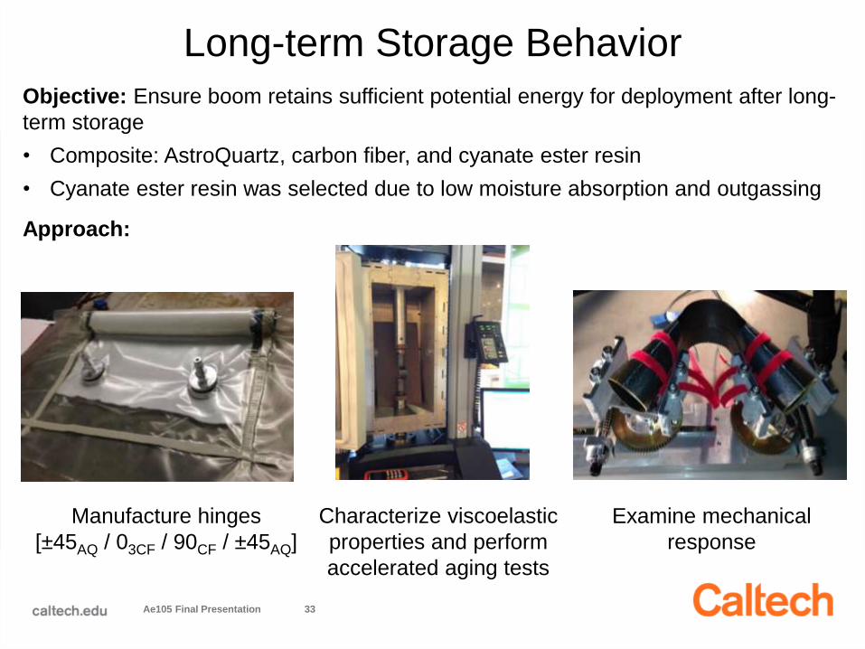
Long-term Storage Behavior
Ae105 Final Presentation 33
Objective: Ensure boom retains sufficient potential energy for deployment after long-
term storage
• Composite: AstroQuartz, carbon fiber, and cyanate ester resin
• Cyanate ester resin was selected due to low moisture absorption and outgassing
Approach:
Manufacture hinges
[±45AQ / 03CF / 90CF / ±45AQ]
Characterize viscoelastic
properties and perform
accelerated aging tests
Examine mechanical
response
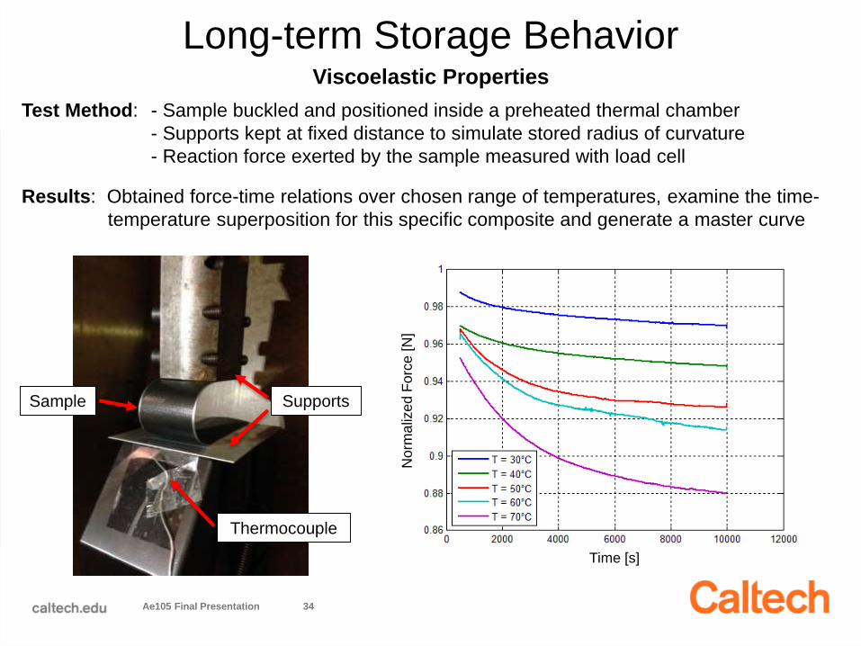
Long-term Storage Behavior
Ae105 Final Presentation 34
Viscoelastic Properties
Test Method: - Sample buckled and positioned inside a preheated thermal chamber
- Supports kept at fixed distance to simulate stored radius of curvature
- Reaction force exerted by the sample measured with load cell
Results: Obtained force-time relations over chosen range of temperatures, examine the time-
temperature superposition for this specific composite and generate a master curve
Sample
Thermocouple
Supports
Time [s]
Norm
aliz
ed
Fo
rce [
N]
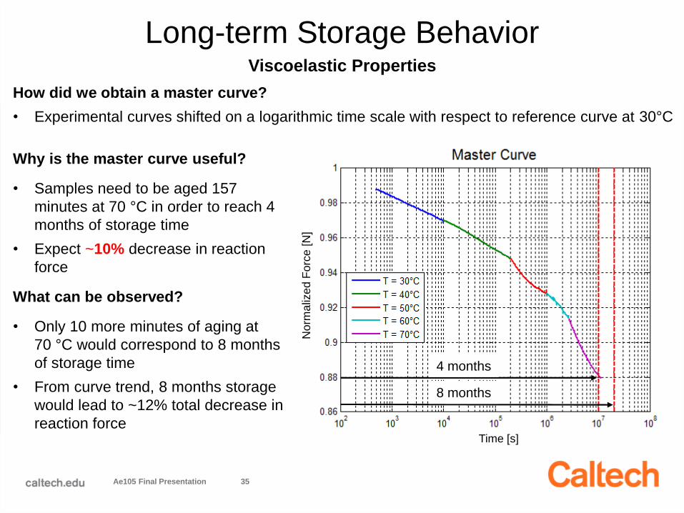
Long-term Storage Behavior
Ae105 Final Presentation 35
Viscoelastic Properties
Why is the master curve useful?
• Samples need to be aged 157
minutes at 70 °C in order to reach 4
months of storage time
• Expect ~10% decrease in reaction
force
What can be observed?
• Only 10 more minutes of aging at
70 °C would correspond to 8 months
of storage time
• From curve trend, 8 months storage
would lead to ~12% total decrease in
reaction force
4 months
8 months
Time [s]
Norm
aliz
ed
Fo
rce [
N]
How did we obtain a master curve?
• Experimental curves shifted on a logarithmic time scale with respect to reference curve at 30°C

Long-term Storage Behavior
Ae105 Final Presentation 36
Mechanical Response
Objective: Measure the moment exerted by the hinge with respect to the hinge configuration,
which is determined by its angle
Results: ~10% decrease in moment if behavior at the peak is neglected
Conclusions: - Quasi-static deployment test confirms master curve prediction
- Reduced moment did not prevent successful hinge deployment
- Information obtained from this test and master curve indicates that longer
storage time will not compromise hinge deployment
θ

Boom-CoreSat Interfaces
37
Separation Device
constrains boom
during storage and
releases stage 1
during deployment
Kinematic Mount allows
adjustment of camera
relative to CoreSat before
final storage
• Corrects for
misalignments
Objective: Validate last year’s designs through
manufacturing and testing & suggest improvements

Ae105 Final Presentation 38
Larger slots to obtain
adjustment range
Wider brackets to
allow boom storage
and deployment
Addition of set
screws to fix the
mandrel
• Manufactured first prototypes from existing designs
• Some modifications were necessary in order to be tested:
Boom-CoreSat Interfaces: Manufacturing

Boom-CoreSat Interfaces: Testing
Ae105 Final Presentation 39
Separation device
• Ran multiple trials at various currents
• Several Vectran configurations and
tensions (need angled cable)
• 9 sec cut time for 1.6 A
• Tension does not affect cutting time
• Reliable: no failure in 26 tests
Kinematic Mount
• More than enough
adjustability in all 3 axes
of rotation
8.5 cm
3°
AxisDegrees of
RotationCamera Lens Displacement
x 4° 11.3 cm
y 3° 8.5 cm
z 6° 1.0 cm
Y
X
Z

Separation Device Testing
Ae105 Final Presentation 40

Boom-CoreSat Interfaces: Future Improvements
Kinematic mount
• Placement of the
Vectran cable
• Resolution of plate
bending issue
• Attachment of boom on mandrel
Ae105 Final Presentation 41
Separation device
• Larger displacement is required
to maintain tension
• Addition of redundancy
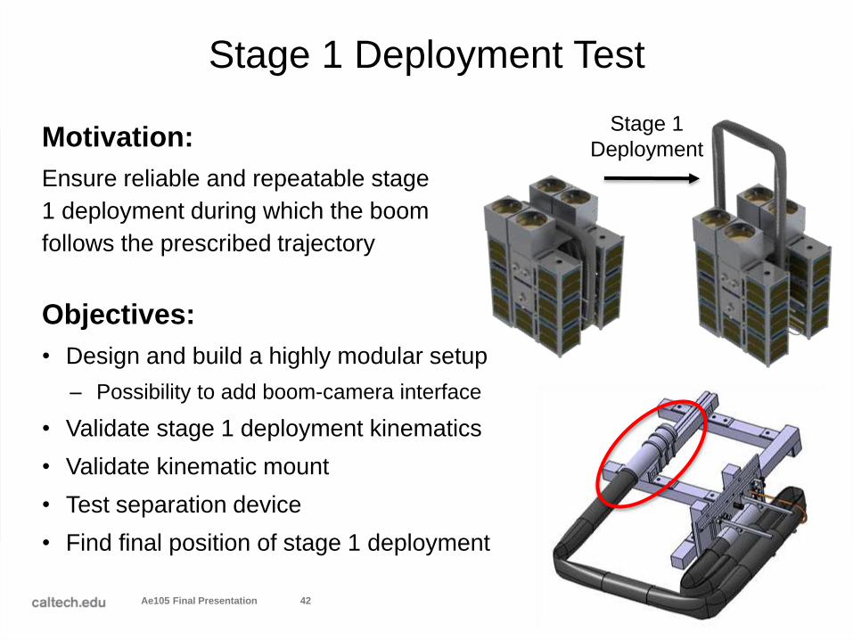
Stage 1 Deployment Test
Motivation:
Ensure reliable and repeatable stage
1 deployment during which the boom
follows the prescribed trajectory
Ae105 Final Presentation 42
Objectives:
• Design and build a highly modular setup
– Possibility to add boom-camera interface
• Validate stage 1 deployment kinematics
• Validate kinematic mount
• Test separation device
• Find final position of stage 1 deployment
Stage 1
Deployment

Ae105 Final Presentation 43
Stage 1 Deployment Test: Video 1

Stage 1 Deployment Test: Video 2
Ae105 Final Presentation 44
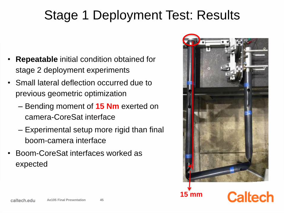
Stage 1 Deployment Test: Results
Ae105 Final Presentation 45
• Repeatable initial condition obtained for
stage 2 deployment experiments
• Small lateral deflection occurred due to
previous geometric optimization
– Bending moment of 15 Nm exerted on
camera-CoreSat interface
– Experimental setup more rigid than final
boom-camera interface
• Boom-CoreSat interfaces worked as
expected
15 mm

Summary of Completed Work
Ae105 Final Presentation 46
Long-Term Storage
• Generated a master curve for cyanate ester resin
• Moment exerted by hinges decreased ~10% after 4 months storage
• Aging did not prevent single hinge deployment
Boom-CoreSat Interfaces
• Manufactured and tested interfaces
• Kinematic Mount: Ample range of motion achieved to align optical systems
• Separation Device: Reliably cuts Vectran wire for stage 1 deployment
Stage Experiments
• Multiple successful stage 1 deployments using interface prototypes
• Characterization of the initial conditions for stage 2 deployment

Future Work
Ae105 Final Presentation 47
Long-Term Storage
• Compare results with FEM
simulations from previous years
• Analyze full boom deflection after
deployment
Boom-CoreSat Interfaces
• Perform separation device tests in vacuum chamber
• Analyze kinematic mount design from thermal and structural
standpoint and make necessary modifications
Stage Experiments
• Complete stage 1 and 2 experiments
• Further analyze the effect of the bending moment exerted on camera-
CoreSat interface
Outgassing
• Identify outgassing level of boom composite and contaminants

Questions?
Ae105 Final Presentation 48

Study of mirror deformations
under thermal loading
Nicolas Meirhaeghe
Pranav Nath
J.P. Voropaieff
Mentor: Christian Kettenbeil

MIRRORS
2x reference
2x deformable
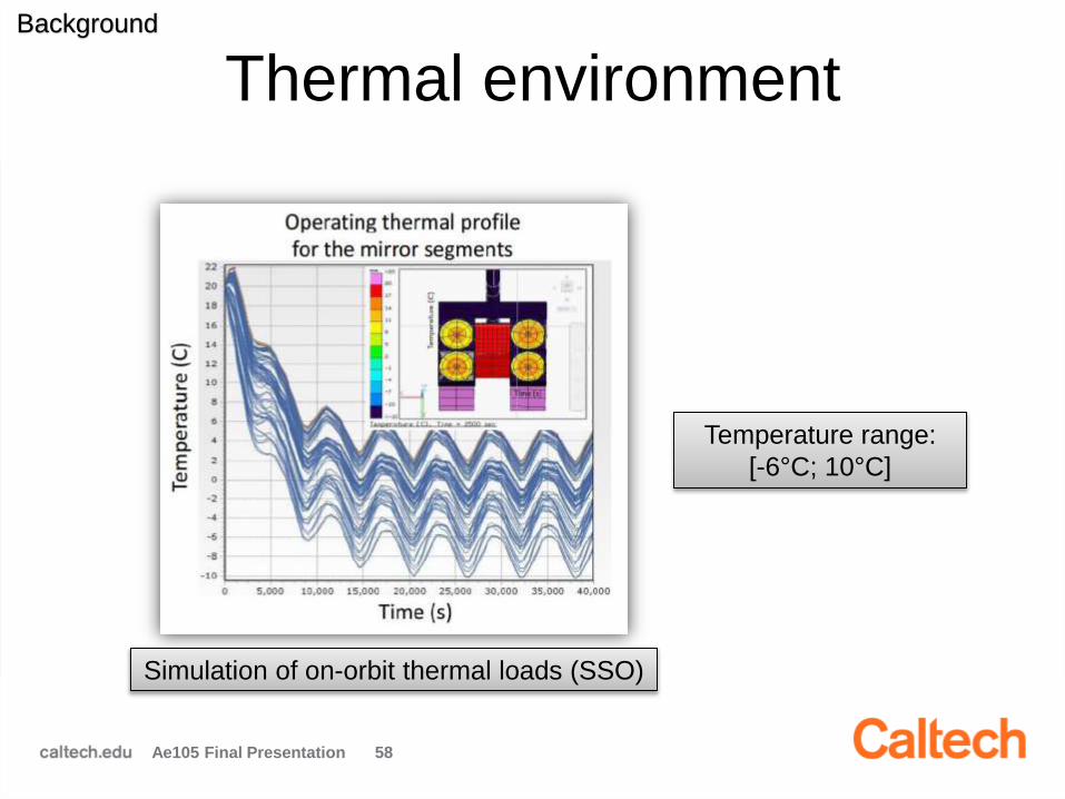
Thermal environment
Ae105 Final Presentation 58
Simulation of on-orbit thermal loads (SSO)
Background
Temperature range:
[-6°C; 10°C]

Mirror Structure
Ae105 Final Presentation 59
Layer Architecture of the
Deformable Mirror (DM)Composition of each layer
Background
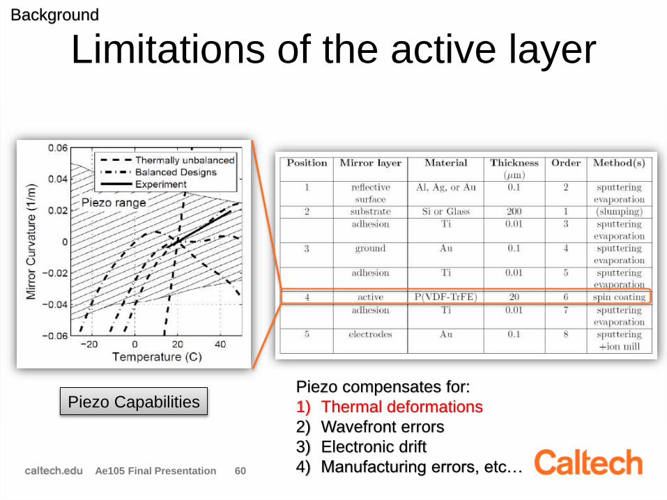
Limitations of the active layer
Ae105 Final Presentation 60
Piezo CapabilitiesPiezo compensates for:
1) Thermal deformations
2) Wavefront errors
3) Electronic drift
4) Manufacturing errors, etc…
Background

Goal of the project
Ae105 Final Presentation 61
“ Ensuring operability of the deformable mirrors
under on-orbit thermal loading conditions ” Keep thermal deformations within piezo range (+ margin)
Operating temperature range [-20℃; 20℃] • Based on simulation (+ margin)
Survivability range [-60℃; 50℃] • Account for:
Drop in temperature when electronics is off
Potential overheating under extreme conditions

Objectives of the project
1) Characterization of pre-designed mirror
samples Testing of 4 different « recipes »
Only reflective layer composition varies
Ae105 Final Presentation 62

Objectives of the project
2) Validation of a theoretical model for
thermal deformation Simplified model (Stoney’s Formula)
Relates radius of curvature of mirror to material
properties of each layer and temperature loading
Ae105 Final Presentation 63

Objectives of the project
3) Optimization of mirror composition Cost function: curvature change over operating
range
Free parameter: thickness of reflective layer
Design recommendations for new mirror
Ae105 Final Presentation 64New mirror design
Optim.
ModelTesting
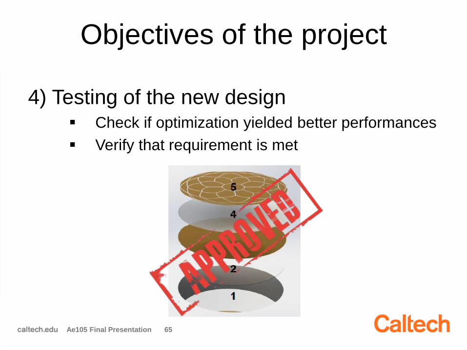
Objectives of the project
4) Testing of the new design Check if optimization yielded better performances
Verify that requirement is met
Ae105 Final Presentation 65

Experimental setup
Ae105 Final Presentation 66
Vacuum chamber
L2
Beam splitter
Laser
L3
SHWS
L1
Vacuum chamber
with cooling system
Shack Hartmann WF sensor

Mirror deformation: defocus
Ae105 Final Presentation 67
Kinematic
mounts
SHWS
measurement
of Sample1

Problems with the old setup
Ae105 Final Presentation 68
Plastic PCB plate
(deforms mirror)
Copper springs
(press against
plate)
Plastic poor conduction

Improvements
Ae105 Final Presentation 69
New setup
• Better conduction
• Included radiation shield
• Aluminum plate stiffer
After improvements:
-4°C on mirror
Aluminum
plate

Sample Testing
Ae105 Final Presentation 70
Sample 1 Sample 3
Sample 3 shows too much initial astigmatism (Z4 & Z6)
Samples 2 and
4 were much
more astigmatic
Objective 1
Only sample 1 used for analysis

Results and Analysis
Ae105 Final Presentation 71
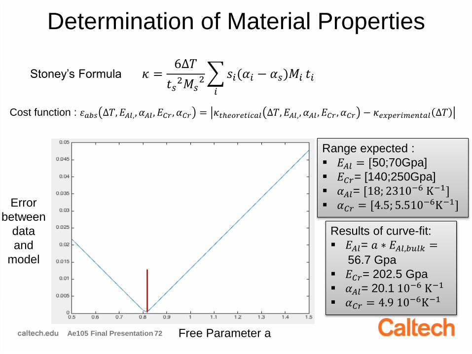
Determination of Material Properties
Ae105 Final Presentation 72
Error
between
data
and
model
Free Parameter a
𝜅 =6∆𝑇
𝑡𝑠2𝑀𝑠
2
𝑖
𝑠𝑖(𝛼𝑖 − 𝛼𝑠)𝑀𝑖 𝑡𝑖
Cost function : 𝜀𝑎𝑏𝑠 ∆𝑇, 𝐸𝐴𝑙,, 𝛼𝐴𝑙 , 𝐸𝐶𝑟 , 𝛼𝐶𝑟 = 𝜅𝑡ℎ𝑒𝑜𝑟𝑒𝑡𝑖𝑐𝑎𝑙 ∆𝑇, 𝐸𝐴𝑙,, 𝛼𝐴𝑙 , 𝐸𝐶𝑟 , 𝛼𝐶𝑟 − 𝜅𝑒𝑥𝑝𝑒𝑟𝑖𝑚𝑒𝑛𝑡𝑎𝑙 ∆𝑇
Results of curve-fit:
𝐸𝐴𝑙= 𝑎 ∗ 𝐸𝐴𝑙,𝑏𝑢𝑙𝑘 =
56.7 Gpa
𝐸𝐶𝑟= 202.5 Gpa
𝛼𝐴𝑙= 20.1 10−6 K−1
𝛼𝐶𝑟 = 4.9 10−6K−1
Range expected :
𝐸𝐴𝑙 = [50;70Gpa]
𝐸𝐶𝑟= [140;250Gpa]
𝛼𝐴𝑙= [18; 2310−6 K−1] 𝛼𝐶𝑟 = [4.5; 5.510−6K−1]
Stoney’s Formula
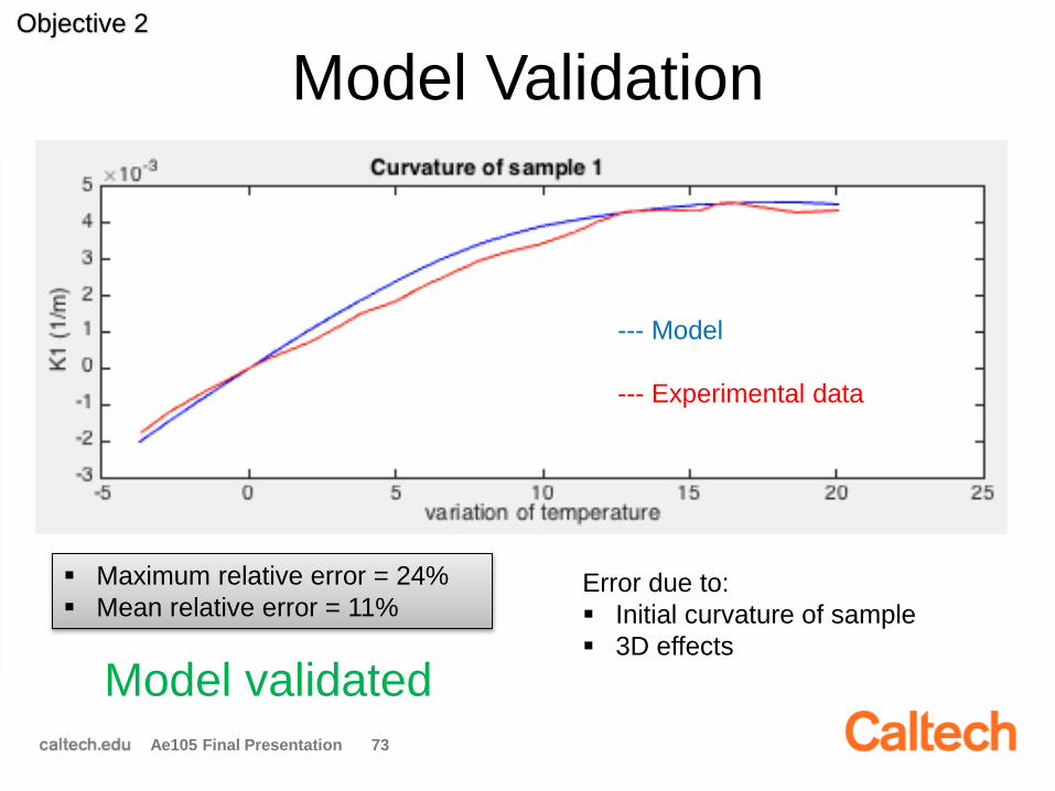
Model Validation
Ae105 Final Presentation 73
Objective 2
--- Model
--- Experimental data
Maximum relative error = 24%
Mean relative error = 11%Error due to:
Initial curvature of sample
3D effects
Model validated

Ae105 Final Presentation
tAl
Optimization strategy
Design choices
Reflective layer composition: Aluminum + Chromium (stiffer)
• 3 sublayers of Al
• 3 sublayers of Cr
Ratio Al/Cr = 10 tCrtCr = tAl / 10
)𝜅(𝑡, ∆𝑇 =6∆𝑇
𝑡𝑠2𝑀𝑠
2 3𝑡 𝛼𝐴𝑙 − 𝛼𝑠 𝑀𝐴𝑙 + 3𝑡
10𝛼𝐶𝑟 − 𝛼𝑠 𝑀𝐶𝑟 −
6∆𝑇
𝑡𝑠2𝑀𝑠
2
𝑗
𝛼𝑗 − 𝛼𝑠)𝑀𝑗 𝑡𝑗
Cost function: 𝜀 𝑡 = 𝑚𝑎𝑥∆𝑇( 𝜅 𝑡, ∆𝑇 )
19

Optimization of reflective layer
Ae105 Final Presentation 75
Final Design Recommendation
for composition of reflective layer:
3 sublayers of Aluminum of
thickness tAl = 1.65 μm
3 sublayers of Chromium of
thickness tCr = 0.165 μm
Overall thickness :
tReflective = 5.445 𝛍m
Objective 3
)𝜀 𝑡𝐴𝑙 = 𝑚𝑎𝑥∆𝑇( 𝜅 𝑡𝐴𝑙, ∆𝑇
𝑡𝐴𝑙

Requirements are met
Ae105 Final Presentation 76
0.0022 m-1
Objective 3

Testing of new design
Latest setup (reached -16℃ on mirror)
Reversed Hartmann
Ae105 Final Presentation 77
Objective 4

Results for new design
Ae105 Final Presentation 78
-15 -10 -5 0 5 100
1
2
3
4
5
6
7
Temperature [0C]
[ m
]
Focus
RMS
Astig 1
Astig 2

Conclusion
Ae105 Final Presentation 79
Work completed:
Testing and characterization of mirror samples
Developed Simulation tool
Optimization of mirror layering
Design recommendation
Testing of new design
Future work:
Improvement of cooling capacities
More testing of latest design
Error budget

Mirror Box
Tatiana Roy
Albert Yang
Mentor: Lee Wilson

Mirror Boxes

Two Types of Mirror Boxes
• Mirror box contains all
required infrastructure for
telescope mirrors
– Two reference (rigid)
mirrors and two
deformable mirrors in total
– Will focus primarily on the
deformable mirrors
Ae105 Final Presentation 88
Reference Mirrors
Deformable Mirrors

Box Subsystems
• Mirrors – Mirrors subsystem
holds the mirror in
place
• Picomotors– Piston/tip/tilt the mirror
• Electronics – House electronics
• Frame – Hold all mirror box
elements and interface
with CoreSat
Ae105 Final Presentation 89
105.6mm
106mm
90mm

CoreSat Interface
• Must match with pre-established Surrey
mechanical and electrical interfaces
Ae105 Final Presentation 90
Cable
Interface
Mechanical
Interfaces
Mechanical
Interfaces
Interface
with Surrey
Functional Requirements
• Survive launch loads
• Provide mechanical support for a set of
deformable mirrors, rigid mirrors, and
mirror electronics
• Allow mirror to operate within the required
range of tip, tilt, and piston positions)
Ae105 Final Presentation 91

Performance Requirements
• Provide tip/tilt of up to 6.85°
Ae105 Final Presentation 92
Picomotors Tilting the Mirror Plate
Mirror Sub-
assembly
Reference
Plate
θ

Mass Budget
• Mass Requirement: <680g per box
Current Best Estimate:
Ae105 Final Presentation 93
Subsystem Current Mass (g) % total Contingency (g) (30%) Total (g)
Mirror* 28 5.5 9 37
Picomotors 263 51.7 79 342
Electronics 38 7.5 12 50
Frame 180 35.4 54 234
Total Mass 509 154 663

Addressing Requirements
• Mirror Mounts
– Updated mount design to solve pinching issue
– Tested new mount design
• Damping Columns
– Designed damping columns to interface with
mirror box and mitigate launch loads
– Chose damping material
• Updated mirror box design
Ae105 Final Presentation 94

Mirror Mount: Old Design
• Curved mirror is extremely thin. Mirror is
prone to deformation near mounting sites
– Old mounts designed
for flat mirrors
– Curved mirrors need
different mounts
– Changes in shape
will lead to reduced
overall performance
Ae105 Final Presentation 95
Old Design Relied on
Cylindrical Magnets

Mirror Mount: New Design
• Designed new mount
– Single point of contact on
each side of the mirror
– Top cage required to retain
magnet
Ae105 Final Presentation 96
Fixed with epoxy
Magnet/Cage minimum clearance
Tangent Line
Sphere Center Line
Old Mounts New Mounts
Tangent Line
Sphere Center Line
Magnet

Testing Mirror Deformations
• Zernike coefficients were calculated using
SHWS to measure deformations– Need 2.4m (radius of curvature) path to SHWS
– Independent test also conducted
– Looking for trefoil shape deformation in mirror
Ae105 Final Presentation 97
Flat Mirror
SHWS Beam Splitter
Mirror Fixture
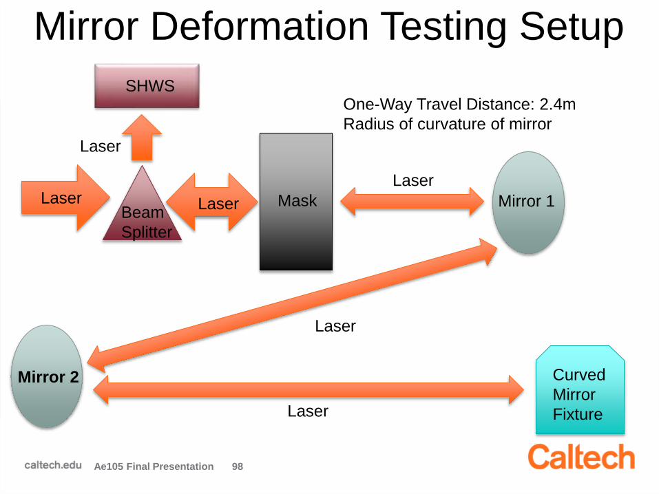
Mirror Deformation Testing Setup
Ae105 Final Presentation 98
LaserBeam
Splitter
Mask Mirror 1
Laser
Laser
Laser
Mirror 2
Laser
Curved
Mirror
Fixture
Laser
SHWSOne-Way Travel Distance: 2.4m
Radius of curvature of mirror

Mirror Mount Deformation Results
• Mirror had high Z4 and Z5 values
• Z9 and Z10 are not present in our test
Consequently, mirror mounts do not deform mirror
Ae105 Final Presentation 99
Z1
Z2 Z3
Z4Z5 Z6
Z8Z9 Z10Z7
Zernike Tested Name
4 .7 Defocus
5 2.5 Oblique Astigmatism
9 <.1 Vertical Trefoil
10 <.1 Oblique Trefoil

Mirror Mount Characterization
• A test was also performed on a Haso SHWS
by Caltech Post-Doc Steve Bongiorno
– Performed on different mirror, manufactured to
have less errors
– Concluded mirror aberration
was dominated by
astigmatism, and not by
any trefoil shape
Ae105 Final Presentation 100 Low Relative Values

Launch Survival• Large vibration loads during launch: Mirror
will vibrate and possibly shatter
Ae105 Final Presentation 101
1.5g lateral
6g vertical
Vert
ical
Lateral
1.5g lateral
3g vertical
2.5g lateral
3g vertical
From Delta IV
Handbook
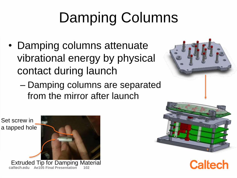
Damping Columns
• Damping columns attenuate
vibrational energy by physical
contact during launch
– Damping columns are separated
from the mirror after launch
Ae105 Final Presentation 102Extruded Tip for Damping Material
Set screw in
a tapped hole

Damping Material
• Chose Red Silicone foam as damping
material
– Reported CVCM (collected volatile
condensable materials) of <0.005 (lowest
possible)
– Rated for -100F to 400F (required -50F to
50F)
Ae105 Final Presentation 103
Threads Into Reference Plate
Damping Material at Top

Updated CAD: Spring Tubes
• Keep mirror plate
connected to reference
plate while still allowing
for normal picomotor
operation
• Springs housed by
tubes connect
reference plate and
mirror plateAe105 Final Presentation 104
One end attaches at
bottom of tube
One end attaches at mirror plate

Summary of Mirror Box Progress
• Designed new mirror mounts to solve
mirror pinching issue
– Prototyped new mounts and characterized
with SHWS test
– Showed no appreciable deformation
• Designed damping columns and chose
damping material
– Fabricated sample damping column
• Updated CAD to reflect design changes
Ae105 Final Presentation 105
Further Work Required
• Finish launch vibration survivability test
– Finish profiling vibration table to make sure it
can reach the frequencies required
• More SHWS tests with different
configurations for the mirror
– Test mirror with current mount vs. no mount
• Design and assemble reference mirror box
Ae105 Final Presentation 106

Questions?
Ae105 Final Presentation 107

Camera Prototyping
Kevin Bonnet
Christopher Chatellier
Monica Li
Mentor: Maria Sakovsky
Camera

1. System Definition
2. Requirements
3. Camera Design
4. Prototype Testing
5. Future Work
Ae105 Final Presentation 122
Overview

Ae105 Final Presentation 123
Imagin
g
Dete
cto
r
SHWS Driver
Imaging
Detector DriverMask Driver
Telescope
CPU
Boom Inspection
Camera (BIC)
ZigBee
Transceiver
Reim
agin
g
Le
ns
Mask
Collim
ato
r
Le
ns
USB to S/C
Light from M1
Mask Motor
Wireless to RMx, DMx
2x C
ub
e B
/S
SHWS DriverSHWS Detector
SHWS Detector
Ima
gin
g D
ete
cto
r
System Definition

124
Performance:
• 80% encircled energy radius < 90% diffraction limit
• 0.3° full field-of-view
• Bandwidth: 465 – 615 nm
• SNR > 100
Constraints:
• Mass < 4kg (Currently 3.82 kg)
• Volume < 10 × 10 × 35 cm (Currently 8.0 x 9.6 x 23.2 cm)
• Power < 5W (Currently ~ 7.1W peak power)
Functional:
• Work with reconfigurable primary mirror (Mask Mech)
• Provide feedback during primary mirror calibration (SHWS)
• Science imaging (Entire Subsystem)
System Requirements

125
Camera Mechanical
• Mask Mechanism
• Beam Splitter
• Component Interfaces
SHWS & Optics
• Mount Design
• Alignment & Calibration
Camera Prototype
• Manufacture & Integrate
• Verification & Validation
Mechanically
Integrated
Camera
Prototype
Task Overview

Ae105 Final Presentation 126
Initial Design
• Mechanical re-design
after optical modeling
• Manufacture collimator &
reimaging groups
• Mass ~ 2.9 kg
Current Design
• Modifications due to interface design
• Finalized & manufactured prototype
• Initial Design for external interfaces
• Mass ~ 3.8 kg (with 10% margin)
Camera Design

Camera Mechanical
Ae105 Final Presentation 127
Baffle
Collimator Group Reimaging Group
Telescope CPU
Imaging
Detector
SHWS Mask
Beam SplitterMotor

Beam Splitter Assembly
• Designed for integration of
neighboring components
• Utilized detents and spring steel to
allow for thermal expansion
Ae105 Final Presentation 128
Detent
Spring Steel

Mask Mechanism
• Designed for change between
two configurations
• Used ray tracing software to
determine optical path at max
field angle (4°from pupil
conjugate)
Ae105 Final Presentation 129
Narrow Wide
dhole = 5mm
dbeam = 4.2mm

DetectorLenslet array
• Designed a mount to account for:
– Small space available
– Mass
– Alignment constraints
• Sank lenslet array into plate with
RTV for padding
Ae105 Final Presentation 130
Shack-Hartmann Wavefront Sensor
CMOS Array
Spiricon Inc. (2004). Hartmann Wavefront Analyzer Tutorial [Online].
Available: http://www.ophiropt.com/user_files/laser/beam_profilers/tutorial-hartman.pdf

External Interfaces
• Frangibolt (FD04)
for CoreSat interface
• Mount with mandrel
for boom interface
• Interfaces aligned
with camera CoM
Ae105 Final Presentation 131
* Image from TiNi Aerospace

Test Plan
132
Component Level Testing
Collimator Group
Beam Splitter
SHWS
Mask Mechanism
Reimaging Group
Detector Mount
End to End Testing
Verify Spot size
Verify Spot shape
Thermal Testing
Shake Testing

Testbed Setup
133
Alignment Testbed
Telescope Testbed

Pass/Fail Criteria
134
Component Criteria
ALL • Light unobstructed & not scattered
Collimator Group • Light is collimated
Beam Splitter • Prism transmits & reflects along axis
SHWS
• MLA is located at pupil conjugate
• SHWS can process the wavefront
• Measurements are repeatable
Mask• Pupil conjugate located at gear rear
• Gears allow change in configuration
Reimaging Group• Focal point is at image detector
surface
Imaging Detector • Image is on detector array
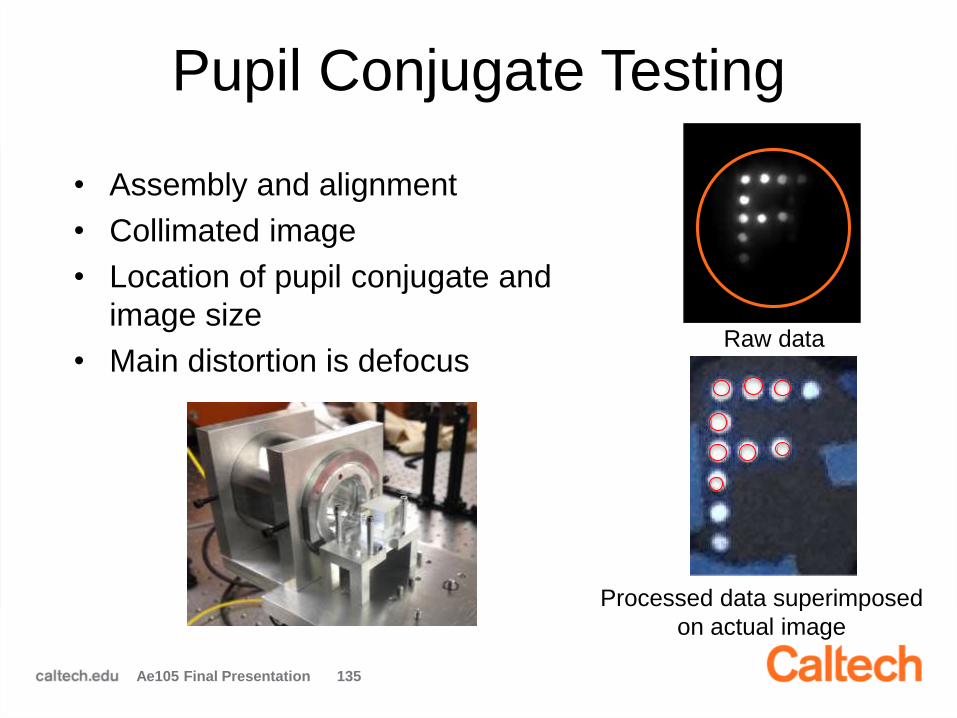
Pupil Conjugate Testing
• Assembly and alignment
• Collimated image
• Location of pupil conjugate and
image size
• Main distortion is defocus
Ae105 Final Presentation 135
Raw data
Processed data superimposed
on actual image

SHWS Alignment
Ae105 Final Presentation 1360
10
20
30
40
0
10
20
30
40-0.05
0
0.05
0.1
0.15
0.2
Lenslet number (x-direction)Lenslet number (y-direction)
Ww
avefr
ont
heig
ht
above r
efe
rence(m
m)
• Extract spot locations (x)
• Compare them to
reference grid (o)
• Compute slope from the
difference between the
locations

Image Detector Testing
• Imaged with point source in test bed
• Deformations in resulting image:
– Astigmatism due to misalignment in the full testbed
– Coma due to off-axis spherical mirrors
• Placing point source at prime focus resulted in expected
spot size (36 µm)
Ae105 Final Presentation 137
Predicted spot size = 36 μm
Full Testbed Set-Up Point Source at Prime Focus

Results
138
Component Criteria Status
ALL • Light unobstructed & not scattered
Collimator Group • Light is collimated
Beam Splitter • Prism transmits & reflects along axis
SHWS
• MLA is located at pupil conjugate
• SHWS can process the wavefront
• Measurements are repeatable
Mask• Pupil conjugate located at gear rear
• Gears allow change in configuration
Reimaging Group • Focal point is at image detector surface
Imaging Detector • Image is on detector array
Pass
In-Progress
Fail

Conclusion
Progress
Re-designed existing
CAD for manufacturability
Fabricated & assembled
camera prototype
Developed a test plan for
both prototype & flight
Initiated component level
testing
Future Work
Complete prototype testing
Integrate stepper motor
Integrate electronics
Integrate light shielding
Finalize external interfaces
Conduct environmental
testing
Ae105 Final Presentation 139

Questions?
Ae105 Final Presentation 140

Mirror Calibration Algorithms
Joseph Bowkett
Greg Phlipot
Mentor: Melanie Delapierre,
Thibaud Talon


Ae105 Final Presentation 151
Overview• Point, center, and focus four mirrors in
reasonable time
• Wavefront error correction
• Implementation and experimental testing
3 Picomotors
Camera &
SHWS
Incoming light
Piezoelectric
Actuators
Mirrors
12
3

Ae105 Final Presentation 152
Telescope Testbed• 2 rigid mirrors with three picomotors each
• Autocollimated light represents distant star
• Linux laptop with flight CPU compatible libraries
Linux laptop

Ae105 Final Presentation 153
Algorithm sequence
1. Blind search 2. Centering
3. Focusing 4. Shape correction
Mirrors
Camera
Image
Plane
Focal
Point

Ae105 Final Presentation 154
Picomotor Characterization
• Need consistent actuation for open loop control
• Forward and reverse directions different
Initial test setup

Ae105 Final Presentation 155
Picomotor Characterization• Non-linear axial spring force causes change
along stroke
• Curve can be used but still has significant
variance 𝜎𝑠𝑡𝑑 𝑑𝑒𝑣
𝜇𝑚𝑒𝑎𝑛≈ 0.1
Fitted envelope and error bars
Shaft Position (mm)
Convers
ion r
atio (
mm
/s)
In situ test setup

Ae105 Final Presentation 156
Blind Search
• Used to point mirrors toward image detector
• No sensor data, literally shooting in the dark
• Previously used 2 picomotors
Our Tasks• Extend to 3 picomotors
• Investigate repeatability
2-picomotor search pattern

Ae105 Final Presentation 157
Blind Search
• Added a degree of freedom to search pattern
θ Declination
Motor 1
Motor 2
Motor 3
Spot on detector
Ae105 Final Presentation 158
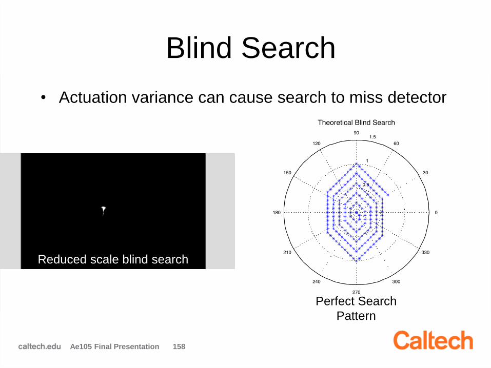
Blind Search
• Actuation variance can cause search to miss detector
Perfect Search
Pattern
Reduced scale blind search

Ae105 Final Presentation 159
Blind Search• Simulation shows success rate by step size for 0.5 degrees
• Needs to be considerably less than ½ orbit (45 min)
Example
Image
Detector
Largest
Gap
Step Size (mm/step) Success % Avg Time (min)
0.052 94% 15.9
0.069 74% 12.2
0.086 12% 10.0
0.104 0% 9.1Image
Detector Size
Perfect Case
(no variance)

Ae105 Final Presentation 160
Centering• Places spots corresponding to all mirrors in
center of image detector
• Previously written for 1 spot
Our Tasks• Extend to multiple spots
• Improve robustness
1-mirror centering

Ae105 Final Presentation 161
Centering: Image Processing
• Eliminate ghost images
• Simulate additional 2 spots
• Centroid and area detection
CVblobs
Raw image with ghost spot
2 real & 2 simulated spots

Ae105 Final Presentation 162
Centering: Rigid Body Motion• Rigid body motion of all spots from transverse
or torsional boom deflection & pointing error
Picomotor
actuated spot
θMirrors
Boom
deflection
Incoming light
θ
Pointing
error
Ae105 Final Presentation 163
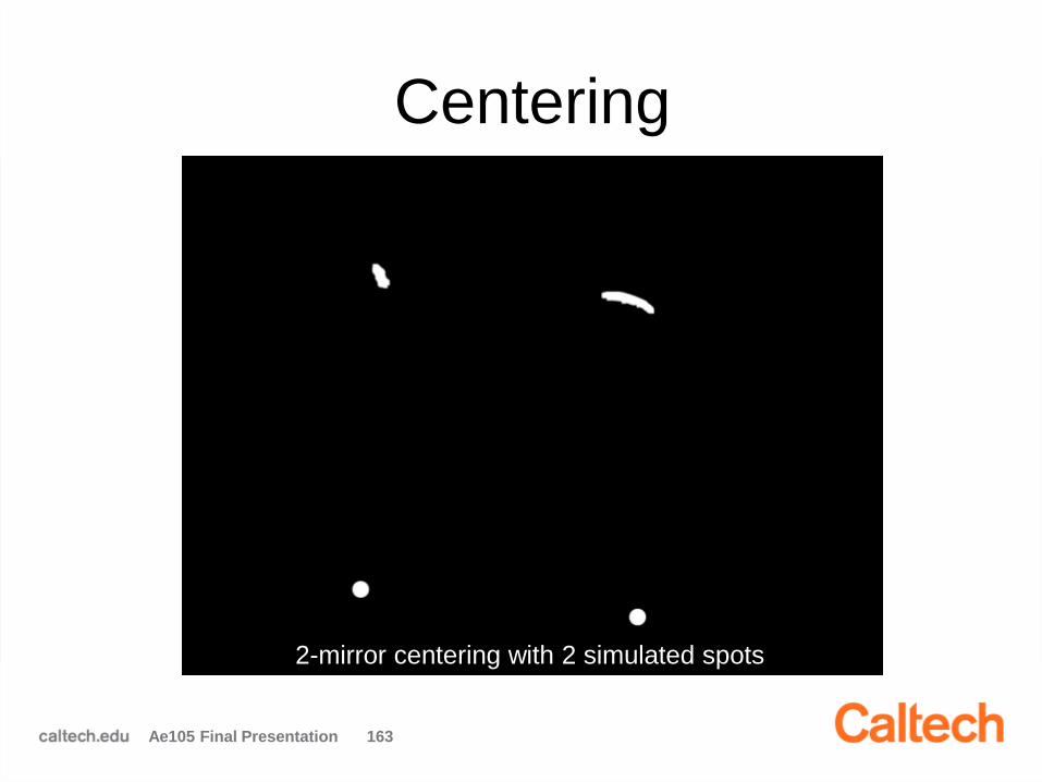
Centering
2-mirror centering with 2 simulated spots

Ae105 Final Presentation 164
Focusing• Moves mirrors in piston to focus images
• Change in spot size undetectable
Δ𝑑 = 1.22𝜆 ∙ Δ𝐿
𝐷
d = spot size
λ = wavelength
L = focal length
D = mirror diameter
Camera
Incoming light
Δ𝐿
Δ𝑑 ≈ 60nm
Pixel size = 2.2μm

Ae105 Final Presentation 165
Shape Correction• Uses 41 piezoelectric actuators to correct shape
of deformable mirrors
Our Tasks• SHWS image processing
• Simulation of closed loop control

Ae105 Final Presentation 166
Shape Correction
• Compute spot errors by
comparing to a reference
image
• Robust to changes in
number of spots
Spot Error

Ae105 Final Presentation 167
Shape Correction• Constrained least
squares minimization
• Simulated
nonlinearity in
actuators by adding
in errorSeparate
Deformed Image
into Mirror
Regions
Calculate Spot
Errors
Create Jacobian
Matrix from
Inluence
Functions
Interpolate
Jacobian at
Reference Spot
Locations
Minimize |J*u-δ|
Vmin<u<Vmax
Introduce Error
Precompiled
At runtime

Ae105 Final Presentation 168
Shape Correction

Ae105 Final Presentation 169
Summary
Fitted envelope and error bars
Shaft Position (mm)Con
ve
rsio
n r
atio
(m
m/s
)
Spot
Error
Characterized Picomotors Improved Blind Search
Extended Centering Capabilities Simulated Deformable Mirrors

Ae105 Final Presentation 170
Future Work
• Test rigid body algorithm on full complement of
mirrors
• Test deformable mirror algorithm on telescope
testbed
• Adapt focusing to use SHWS data
• Test algorithms on the flight CPU

Ae105 Final Presentation 171
Questions?

O is for OBSWOnboard Software
Finn Carlsvi
Chiraag Nataraj
Mentor: Yuchen Wei
Adviser: Dan Scharf


Purpose of On-Board Software
• Controls hardware
• Enables autonomy
• Relays science and engineering data
• Fault detection and recovery
Ae105 Final Presentation 182

Overall Group Task
• Analyze mission requirements
• Define an overall software architecture
• Implement design
Ae105 Final Presentation 183
Achievements
• Performed a detailed mission analysis
• Designed the OBSW framework
• Implemented the OBSW on flight hardware
Ae105 Final Presentation 184

Detailed Mission Analysis
• Gathered information from other teams
• Mission Requirements Document (MRD)
– Based on ConOps and team meetings
– Used James Web Space Telescope MRD as
template
• Software Requirements Specification (SRS)
– Based on MRD
– Used IEEE 830 standard
– Used as foundation for system design
Ae105 Final Presentation 185
Mission Analysis
System Architecture
Design Implementation

SRS
• Software Requirements Specification
– Functional requirements
– Non-functional requirements
– Interface definitions and communication
standards
– Provides traceability
– Provides testability
Ae105 Final Presentation 186
Mission Analysis
System Architecture
Design Implementation

System Architecture
• Hardware Design
– Peripherals and Interfaces
• Operating System
– Scheduling and Hardware Abstraction
• Software Architecture
– Control and Logic
Ae105 Final Presentation 187
Mission Analysis
System Architecture
Design Implementation

Payload Hardware
Ae105 Final Presentation 188
Camera Software
(Spring 2015)
Mission Analysis
System Architecture
Design Implementation
MPUSHWS 1&2 Imager Camera
Boom Camera ZigBee
Motor Controller Mask Limit Sw Thermocouple
Core Sat
MCUHV Board Electrodes
Pico Motors ZigBee
HV Divider Pico Limit Sw Thermocouple
MCUHV Board Electrodes
ZigBee
HV Divider Thermocouple
Mirror Sat
MPU Microprocessor UnitMCU Microcontroller UnitSHWS Shack Hartmann Wavefront SensorHV High Voltage
2x Deformable Mirror Box
Camera Payload
2x Reference Mirror Box
UART
I2C
Zigbee Wireless
Unknown
Analog
USB 2.0
Digital
Legend

Camera Computer
Ae105 Final Presentation 189
• Flight computer selected
• Linux AT91 Kernel
– Issue: Non mainstream kernel
• Challenge: Preemptive scheduling
– Threads must execute on time
– Scheduling is currently not defined
– A patch must be modified
Mission Analysis
System Architecture
Design Implementation
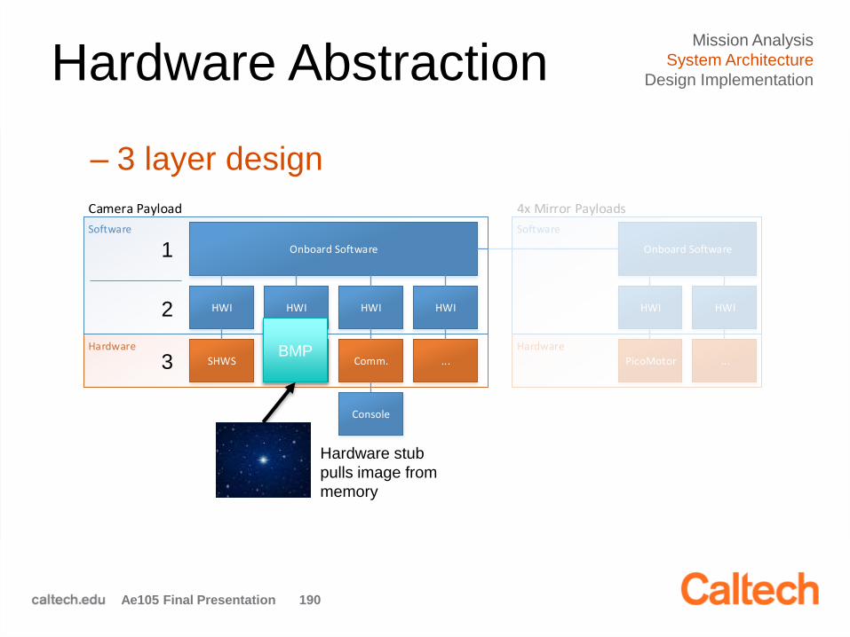
Hardware Abstraction
Ae105 Final Presentation 190
Hardware
Software
Onboard Software
HWI HWI HWI HWI
SHWS Camera Comm. ...
Camera Payload
Hardware
Software
Onboard Software
HWI HWI
PicoMotor ...
4x Mirror Payloads
Console
BMP
Hardware stub
pulls image from
memory
Mission Analysis
System Architecture
Design Implementation
1
2
3
– 3 layer design

Software Architecture
Ae105 Final Presentation 191
Linux Scheduler
Fault Injection
C+DH
Event Manager
Fault Protection
Other
Main Spawn 1 / sec
High Priority
1 / sec
Low Priority
1 / sec
Interrupts
Commands
Mirror Data
Mission Analysis
System Architecture
Design Implementation
• Has been implemented in C
– Demo on Flight Computer will follow

Command and
Data Handling
Ae105 Final Presentation 192
• Handles all external communication
Serial Ports
Shared Memory
C+DH
Earth COM Mirror COM
Telecommand Telemetry Log
All other threads
Mission Analysis
System Architecture
Design ImplementationLinux Scheduler
Fault Injection
C+DH
Event Manager
Fault Protection
Other
Main Spawn 1 / sec
High Priority
1 / sec
Low Priority
1 / sec
Interrupts
Commands
Mirror Data

Event Manager
• Executes functions based on
– Satellite state
– Events and telecommands
Ae105 Final Presentation 193
Mission Analysis
System Architecture
Design ImplementationLinux Scheduler
Fault Injection
C+DH
Event Manager
Fault Protection
Other
Main Spawn 1 / sec
High Priority
1 / sec
Low Priority
1 / sec
Interrupts
Commands
Mirror Data
Post Launch Test
do / Hardware testexit / Hardware test
Boom Deployment 1
entry / Deploy boom primary
boom1_deployment_command
Boom Deployment 2
entry / Deploy boom secondary
boom2_deployment_command
Safe Mode
do / Low power
system_error
change_state_command
system_error
change_state_command
system_error
change_state_command

Fault Protection
• Acts as software watchdog
Ae105 Final Presentation 194
Mission Analysis
System Architecture
Design ImplementationLinux Scheduler
Fault Injection
C+DH
Event Manager
Fault Protection
Other
Main Spawn 1 / sec
High Priority
1 / sec
Low Priority
1 / sec
Interrupts
Commands
Mirror Data
Software
C+DH
Event Manager
Other
Hardware WatchdogFault Protection
• Monitors engineering data
– Temperature, Power, …

Fault Injection
Ae105 Final Presentation 195
Simulated Hardware
Simulated Hardware
Processor EmulatorMemory Stub
Filesystem Stub
Communication Stub
Ha
rdw
are
Stu
b
Ha
rdw
are
Stu
b
Ha
rdw
are
Stu
b
OBSW
C+DH
Event Manager
Fault Protector
Real Hardware
Real ProcessorReal Memory
Real Filesystem
Real Communication
Ha
rdw
are
Stu
b
Ha
rdw
are
Stu
b
Ha
rdw
are
Stu
b
OBSW
C+DH
Event Manager
Fault Protector
Mission Analysis
System Architecture
Design ImplementationLinux Scheduler
Fault Injection
C+DH
Event Manager
Fault Protection
Other
Main Spawn 1 / sec
High Priority
1 / sec
Low Priority
1 / sec
Interrupts
Commands
Mirror Data

Design Implementation
Ae105 Final Presentation 196
Mission Analysis
System Architecture
Design Implementation
• Memory
– Run Time and Long Term
• Communication
– Uplink and Downlink
• Demo
– Image Acquisition
– (Fault Injection)

Memory
Ae105 Final Presentation 197
Mission Analysis
System Architecture
Design Implementation
• Run Time
– C Struct
– Easy for memory
dump
• Long Term
– ASCII Files
state
shws_select
POWER
image
shws_1
shws_2
telecommand
...
Memory
log
File
image
File

Uplink Communication
Ae105 Final Presentation 198
Command File StructureTelecommand Structure
xBC Beginning of Command
x00 Command Length
x00 Command Type
x00
Command Data
xEC End of Command
1
2
3
4
5
6
CRC
Each block is
one byte
Multiple
bytes
Mission Analysis
System Architecture
Design Implementation
• Telecommands
– Commands sent as list with CRC

Downlink Communication
Ae105 Final Presentation 199
Mission Analysis
System Architecture
Design Implementation
• Event Reports
• Telemetry (Science and Engineering)
Science Telemetry PackageEngineering Telemetry PackageEvent Report Package
xBC
x10
x00
xEC
Beginning
Log
Log ID
End
xBC
x20
x00
x00
Beginning
Engineering Telemetry
Data
CRC
x00 Data length
x00 Eng. TM ID
xBC
x30
x00
Beginning
Science Telemetry
Data
x00 Data length
x00 Sci. TM ID
xEC End
x00CRC
xEC End
x00 CRC

Demo Image Acquisition
Ae105 Final Presentation 200
Mission Analysis
System Architecture
Design Implementation
Ground Station
Flight Computer
Telecommand
OBSW
Telemetry
Event Report
Image

Demo Image Acquisition
Ae105 Final Presentation 201
Mission Analysis
System Architecture
Design Implementation
Shared Memory
Event Manager
Command and Data Handling
Ground
Transmit command file
Receive telemetry and event report
Extract image
Create image command
Receive command file
CRC and extract commands
Transmit telemetryand event report
State IS Calibration and Imaging
Call imaging function
State NOT Calibration and Imaging
No image event report
Image event report
Read image command
Read image command
Event Report and Telemetry
Telecommands

OBSW - Future Work
• Improve & extend the functions of telescope software
– Improve the existing function modules
– Complete interface layer with camera hardware (SHWS, image detector)
– Add TC/TM with reference & deformable mirror boxes
• OBSW design for mirror CPU– Communication with telescope CPU
– Operation and failure handling for mirror boxes
• Continue work on software requirements specification
– Need to specify the TC/TM format with Surrey
• System integration test – Unit test for OBSW modules
– Hardware in the loop test