Adafruit 16x2 Character LCD + Keypad for Raspberry Pi · Adafruit 16x2 Character LCD + Keypad for...
17
Adafruit 16x2 Character LCD + Keypad for Raspberry Pi Created by Ladyada Last updated on 2014-03-16 12:32:29 AM EDT
-
Upload
truongdang -
Category
Documents
-
view
244 -
download
0
Transcript of Adafruit 16x2 Character LCD + Keypad for Raspberry Pi · Adafruit 16x2 Character LCD + Keypad for...

Adafruit 16x2 Character LCD + Keypad for Raspberry PiCreated by Ladyada
Last updated on 2014-03-16 12:32:29 AM EDT

2355555566667
1818191920202022
Guide Contents
Guide ContentsOverviewParts List
1) Resistors2) Potentiometer3) Pushbuttons4) i2c Port Expander Chip5) Male Header Pins6) Printed Circuit Board7) Raspberry Pi Plate Header8) BumperAdditional
AssemblyUsageSetting up your Pi for I2CUsing the example Python codeTesting the LibraryAdjusting ContrastPress some buttons!Using the library codeDownload
© Adafruit Industries http://learn.adafruit.com/adafruit-16x2-character-lcd-plus-keypad-for-raspberry-pi
Page 2 of 22

Overview
This new Adafruit plate makes it easy to use a 16x2 Character LCD. We really like the range ofLCDs we stock in the shop, such as our classic blue & white (http://adafru.it/181) as well as thefancy RGB negative (http://adafru.it/399) and RGB positive (http://adafru.it/398). Unfortunately,these LCDs do require quite a few digital pins, 6 to control the LCD and then perhaps another 3to control the RGB backlight for a total of 9 pins. That's nearly all the GPIO available on aRaspberry Pi!
With this in mind, we wanted to make it easier for people to get these LCD into their projects sowe devised a Pi plate that lets you control a 16x2 Character LCD, up to 3 backlight pins
© Adafruit Industries http://learn.adafruit.com/adafruit-16x2-character-lcd-plus-keypad-for-raspberry-pi
Page 3 of 22

AND 5 keypad pins using only the two I2C pins on the Pi! The best part is you don'treally lose those two pins either, since you can stick i2c-based sensors, RTCs, etc and havethem share the I2C bus. This is a super slick way to add a display without all the wiring hassle.
This plate is perfect for when you want to build a stand-alone project with its own userinterface. The 4 directional buttons plus select button allows basic control without having toattach a bulky computer.
The kit is designed for any Raspberry Pi - version 1 and 2.
If you want plug in a Cobbler or Gertboard at the same time, check out our Stacking Header,you can fit an IDC cable over it if the Plate is assembled with this part. (http://adafru.it/1112)
© Adafruit Industries http://learn.adafruit.com/adafruit-16x2-character-lcd-plus-keypad-for-raspberry-pi
Page 4 of 22

Parts List
Check to make sure your kit comes with the following parts.Sometimes we make mistakes sodouble check everything and email [email protected] if you need replacements!
We recently adjusted the kit so the buttons are on the RIGHT side instead ofthe left. The parts list is otherwise the same, its just a little more stable thanbefore
1) ResistorsThere is a total of 3 resistors in this kit. For resistors labeled RED and BLUE on the PCB, they are1/4W 5% 220 ohm resistors (Red, Red, Brown, Gold). For the resistor labeled GREEN on thePCB, it is a 1/4W 5% 330 ohm resistor (Orange Orange Brown Gold).
2) PotentiometerThere is one 10k trim potentiometer. This part will go in the spot labeled Contrast
3) PushbuttonsThere are a total of 5 x 6mm tactile switch pushbuttons. These will be used in the UP, DOWN,LEFT, RIGHT and SELECT locations on the PCB.
4) i2c Port Expander ChipThere is one of these MCP23017 i2c (16 input/output) port expander chips in the kit. This is howwe are able to only use 2 R-Pi pins to run the entire LCD and buttons. Click here for more info onthis chip. (http://adafru.it/732)
5) Male Header Pins
© Adafruit Industries http://learn.adafruit.com/adafruit-16x2-character-lcd-plus-keypad-for-raspberry-pi
Page 5 of 22

There is one strip of 36 male header pins in the kit. These will be used to attach the LCD to thePCB.
6) Printed Circuit BoardThere will be one PCB in the kit as shown above.
7) Raspberry Pi Plate HeaderThere will be one extra-tall 26 pin female header for plugging into the Pi
8) BumperThere will be one rubber bumper as shown above
AdditionalYou'll want an LCD to place into the shield. This isn't included by default since a lot of peoplealready have LCDs they may want to use. (We do sell these in packs however so chances areyou did get an LCD with your order).
Your LCD may have 16 pins (Monochrome) or 18 pins (RGB) and may have 2rows of connectors or one. This is normal and does not affect the display
You can also use 16x2 LCDs that are the same size that do not have an RGBbacklight, or have no backlight at all.
We carry Negative type (http://adafru.it/399) or Positive type (http://adafru.it/398) LCDs as wellas Blue and White LCDs (http://adafru.it/181)
© Adafruit Industries http://learn.adafruit.com/adafruit-16x2-character-lcd-plus-keypad-for-raspberry-pi
Page 6 of 22

Assembly
Check the kit against the to verify youhave all the parts necessary
We recently adjusted the kit sothe buttons are on the right sideinstead of the left. The parts list isotherwise the same, its just alittle more stable than before
Put the printed circuit board into a vise orboard holder, heat up your soldering ironand make sure you're ready to go! We'll start with the first resistor GREEN -which has orange, orange, brown, goldbands on it. This resistor acts as thebacklight control resistor for the greenbacklight pin.
Bend the resistor into a 'staple' and slideit into the slot marked GREEN on thePCB. Resistors do not have a direction soyou can put it in 'either way' and it'll workfind.
© Adafruit Industries http://learn.adafruit.com/adafruit-16x2-character-lcd-plus-keypad-for-raspberry-pi
Page 7 of 22

Bend the 'legs' of the resistor out so itsits flat against the PCB and flip it over.
This way the resistor won't fall out whilesoldering.
With your soldering iron heated up andready, solder in both leads of theresistor. To do this, heat up the roundring pad and the wire lead at the sametime for 2 or 3 seconds, then dip the endof the solder into the heated joint to meltit in.
Then remove the solder and thesoldering iron.
Once the soldering is complete, we canclean up by clipping the leads of theresistor. This keeps them from shortingto something else. Use diagonal or flushcutters to clip the wires right abovewhere the solder joint ends.
© Adafruit Industries http://learn.adafruit.com/adafruit-16x2-character-lcd-plus-keypad-for-raspberry-pi
Page 8 of 22

Since you did so great with the firstresistor, we'll place all of the rest now atthe same time.
The two 220 ohmresistors RED and BLUE - namedbecause they are the backlight seriesresistors for the RGB backlights on theLCDs. These resistors are colored RedRed Brown Gold.
Solder the resistors just like you did withthe first one.
© Adafruit Industries http://learn.adafruit.com/adafruit-16x2-character-lcd-plus-keypad-for-raspberry-pi
Page 9 of 22

Clip all the leads.
Next up we will place the buttons. Thesebuttons are useful to send a signal to thePi (say if you have a basic menu system).We have a 4-way 'direction pad' forup/down/left/right input and a button tothe right called SELECT. These 5 buttonsshould be able to make 'talking' back toyour project easy. These are connectedto the I2C port expander chip so theyrequire no extra pins on the Pi, our librarydoes the work of reading whether theyare pressed.
All the buttons are the same, and theyshould snap nicely into place. Press downonto each button until it snaps in and sitsflat against the PCB.
We recently adjusted the kit sothe buttons are on the RIGHT sideinstead of the left. The buttonssnap in the same but they're onthe right
© Adafruit Industries http://learn.adafruit.com/adafruit-16x2-character-lcd-plus-keypad-for-raspberry-pi
Page 10 of 22

Flip over the PCB and check that all thelegs for the buttons are sticking out.
Solder each leg, taking care not toaccidentally 'short' two button legstogether. The ones for the directionalpads are very close!
Next, place the 10K potentiometer (theorange-faced thing with three legs) intothe spot above the RESET button. It willonly fit one way. This is the contrastpotentiometer which will adjust how darkthe characters appear. All displays areslightly different so you'll adjust this oncethe display is soldered in.
The kit may come with twopotentiometers - a big blue one forbreadboarding the LCD and a smallerorange one for the shield kit. You canthrow away or recycle the blue one, useonly the orange one here!
We recently adjusted the kit to have thepotentiometer in the center rather thanthe right, goes in the same way, just inthe middle!
© Adafruit Industries http://learn.adafruit.com/adafruit-16x2-character-lcd-plus-keypad-for-raspberry-pi
Page 11 of 22

Flip over the PCB and solder in the threelegs of the potentiometer
We're nearly done! Now we will place theI2C port expander chip. Double checkthat it has the MCP23017-E/SPmarking on it. This is a 16-pin expanderchip, that uses the i2c bus. That meansyou can send it commands using the i2cpins on an Pi and control 16 more digitalpins! 5 of those pins go to the buttons, 6go to the LCD control and 3 are used forthe backlight (the remaining 2 areunused).
Unlike buttons or resistors, chips do havea direction and the must be put in theright way! First, use a flat table tocarefully bend the legs of the chip sothey are parallel. Then slip it into thesilkscreened outline so that the notch atthe end of the chip is on the right. Clickthe image to the left to make absolutelysure you've got it in the right way. Onceyou are sure, press the chip into place
We recently adjusted the kit so the chipis more to the left, its the samealignment, just shifted over
© Adafruit Industries http://learn.adafruit.com/adafruit-16x2-character-lcd-plus-keypad-for-raspberry-pi
Page 12 of 22

Flip over the PCB and solder in the 28 pinsof the port expander.
Next we will attach the header, there is astandard 'extra tall' header included in thekit. However, if you want to attach acobbler or GertBoard, etc to the plate,you may want to opt for one of ourstacking headers, they're extra long soyou can plug in an IDC cable on top!
© Adafruit Industries http://learn.adafruit.com/adafruit-16x2-character-lcd-plus-keypad-for-raspberry-pi
Page 13 of 22

Before we solder in the header, removethe bumper from the backing and attachit on the underneath so its right over theEthernet jack when the PCB is plugged in.
On kits where the buttons are on the left,put it right below the contrast pot, asshown. This will keep the pot fromtouching the Ethernet jack.
On kits where the buttons are on theright, put it right next to the buttons (itshouldnt overlap any button legs) sittingflat
Place the 2x13 header onto your Pi, andslide the plate on top, it should fitperfectly.
© Adafruit Industries http://learn.adafruit.com/adafruit-16x2-character-lcd-plus-keypad-for-raspberry-pi
Page 14 of 22
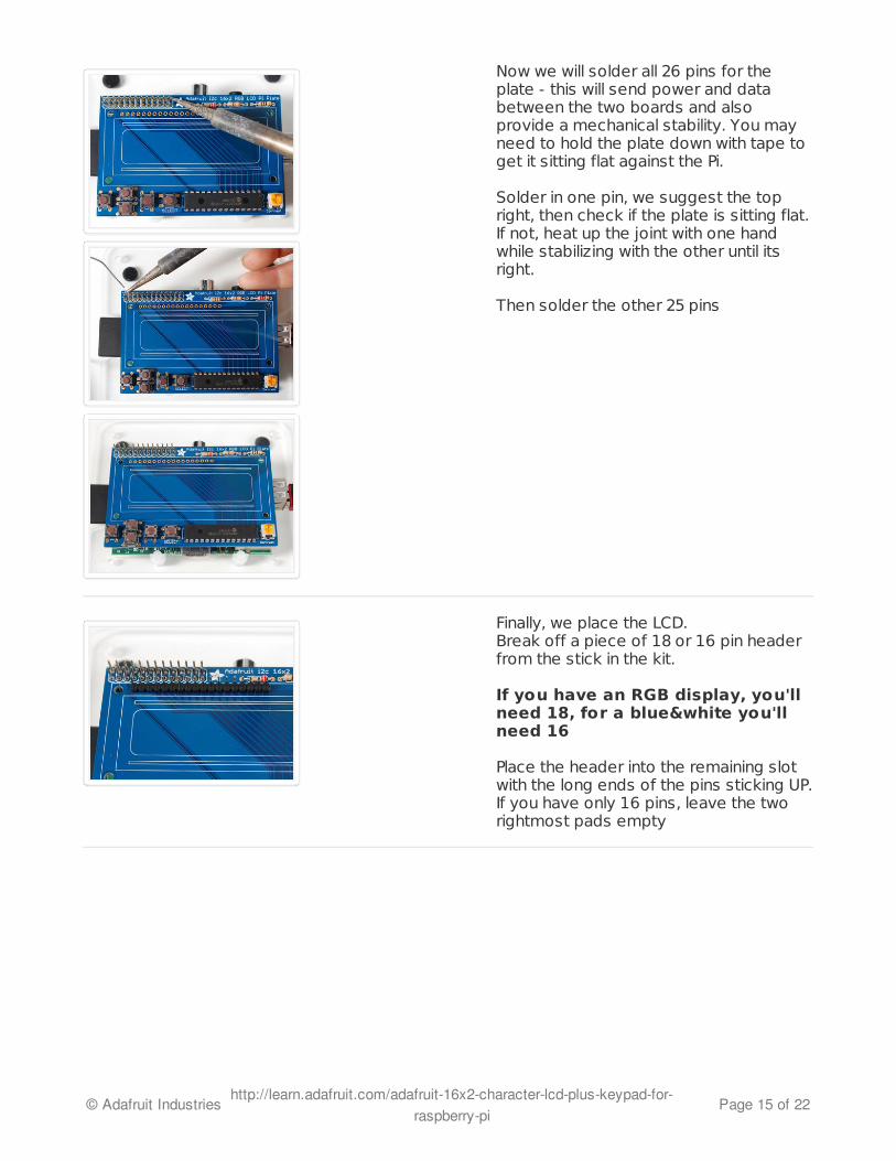
Now we will solder all 26 pins for theplate - this will send power and databetween the two boards and alsoprovide a mechanical stability. You mayneed to hold the plate down with tape toget it sitting flat against the Pi.
Solder in one pin, we suggest the topright, then check if the plate is sitting flat.If not, heat up the joint with one handwhile stabilizing with the other until itsright.
Then solder the other 25 pins
Finally, we place the LCD. Break off a piece of 18 or 16 pin headerfrom the stick in the kit.
If you have an RGB display, you'llneed 18, for a blue&white you'llneed 16
Place the header into the remaining slotwith the long ends of the pins sticking UP.If you have only 16 pins, leave the tworightmost pads empty
© Adafruit Industries http://learn.adafruit.com/adafruit-16x2-character-lcd-plus-keypad-for-raspberry-pi
Page 15 of 22

Slide the LCD over the header so that it isperfectly centered over the four holesand the silkscreen.
Your LCD may have two rows ofconnectors or one row. If its atwo-row-connector LCD we do notuse the bottom row, just continueusing the LCD as it will fit justfine!
The LCD should 'snap' in against thebuttons
Solder all the pins!
© Adafruit Industries http://learn.adafruit.com/adafruit-16x2-character-lcd-plus-keypad-for-raspberry-pi
Page 16 of 22
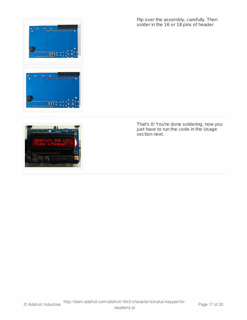
Flip over the assembly, carefully. Thensolder in the 16 or 18 pins of header
That's it! You're done soldering, now youjust have to run the code in the Usagesection next.
© Adafruit Industries http://learn.adafruit.com/adafruit-16x2-character-lcd-plus-keypad-for-raspberry-pi
Page 17 of 22