Accelerometer and multi-sensor technologyread.pudn.com/downloads165/ebook/756655/Strapdown...
21
6.1 Introduction As described in Chapter 1, inertial navigation relies upon the measurement of acceleration which can be integrated successively to provide estimates of changes in velocity and position. Measurements of acceleration are used in preference to direct measurements of velocity or position because velocity and position measurements require an external reference whilst acceleration can be measured internally. The form of construction of devices which may be used to sense acceleration may be classified as either mechanical or 'solid-state'. The technology of mechanical sensors is well established [I 5 2] and devices capable of sensing acceleration over a wide accuracy range, from 50 milli-g down to a few micro-gs and to a similar level of resolution, are currently available. There have been significant advances in the development of solid-state sensors in recent years, particularly with silicon technology. The concept of using a single instrument to measure acceleration and angular motion has been the subject of research for a number of decades and during the 1980s was developed by a number of institutions and companies. This device has become known as the multi-sensor and has tended to be based on either vibratory technology or gyroscopic mass unbalance technology. Evaluation of this technology has generally shown it to be capable of providing estimates of linear acceleration and angular motion compatible with sub-inertial 1 navigation applications. 6.2 The measurement of translational motion The translational acceleration of a rigid body, resulting from the forces acting upon it, is described by Newton's second law of motion. A force F acting on a body of mass The term sub-inertial is sometimes used when describing system performance for short duration navigation systems. Typically, sub-inertial systems use gyroscopes and accelerometers with measurement biases of the order of l°/h and 1 milli-g (Ia), respectively. Chapter 6 Accelerometer and multi-sensor technology
Transcript of Accelerometer and multi-sensor technologyread.pudn.com/downloads165/ebook/756655/Strapdown...

6.1 Introduction
As described in Chapter 1, inertial navigation relies upon the measurement ofacceleration which can be integrated successively to provide estimates of changes invelocity and position. Measurements of acceleration are used in preference to directmeasurements of velocity or position because velocity and position measurementsrequire an external reference whilst acceleration can be measured internally.
The form of construction of devices which may be used to sense accelerationmay be classified as either mechanical or 'solid-state'. The technology of mechanicalsensors is well established [I5 2] and devices capable of sensing acceleration overa wide accuracy range, from 50 milli-g down to a few micro-gs and to a similarlevel of resolution, are currently available. There have been significant advancesin the development of solid-state sensors in recent years, particularly with silicontechnology.
The concept of using a single instrument to measure acceleration and angularmotion has been the subject of research for a number of decades and during the1980s was developed by a number of institutions and companies. This device hasbecome known as the multi-sensor and has tended to be based on either vibratorytechnology or gyroscopic mass unbalance technology. Evaluation of this technologyhas generally shown it to be capable of providing estimates of linear accelerationand angular motion compatible with sub-inertial1 navigation applications.
6.2 The measurement of translational motion
The translational acceleration of a rigid body, resulting from the forces acting upon it,is described by Newton's second law of motion. A force F acting on a body of mass
The term sub-inertial is sometimes used when describing system performance for short durationnavigation systems. Typically, sub-inertial systems use gyroscopes and accelerometers with measurementbiases of the order of l°/h and 1 milli-g (Ia), respectively.
Chapter 6
Accelerometer and multi-sensor technology

m causes the body to accelerate with respect to inertial space. This acceleration (a)is given by:
F = ma (6.1)
Whilst it is not practical to determine the acceleration of a vehicle by measuringthe total force acting upon it, it is possible to measure the force acting on a smallmass contained within the vehicle which is constrained to move with the vehicle.The small mass, known as a proof or seismic mass, forms part of an instrumentcalled an accelerometer. In its simplest form, the accelerometer contains a proof massconnected via a spring to the case of the instrument as shown in Figure 6.1.
When the case of the instrument is subjected to an acceleration along its sensitiveaxis, as indicted in the figure, the proof mass tends to resist the change in movementowing to its own inertia. As a result, the mass is displaced with respect to the body.Under steady state conditions, the force acting on the mass will be balanced by thetension in the spring, the net extension of the spring providing a measure of theapplied force, which is proportional to the acceleration.
The total force (F) acting on a mass (m) in space may be represented by theequation:
F = ma = mf H- mg (6.2)
where / is the acceleration produced by forces other than the gravitational field. In thecase of a unit mass, F = a = f+g. The acceleration (a) may be expressed as the totalforce per unit mass. An accelerometer is insensitive to the gravitational acceleration(g) and thus provides an output proportional to the non-gravitational force per unitmass ( /) to which the sensor is subjected along its sensitive axis. As described inChapter 2, this is referred to as the specific force exerted on the sensor.
Accelerationwith respect toinertial space
Displacementpick-off
Case
Proofmass(m)
Spring
Signalproportionalto specific
force(f)
Figure 6.1 A simple accelerometer

Taking the case of an accelerometer which is falling freely within a gravitationalfield, the case and the proof mass will fall together with the result that there will beno net extension of the spring. Hence, the output of the instrument will remain atzero. In this situation, the acceleration of the instrument with respect to an inertiallyfixed set of axes, a = g and the specific force is zero in accordance with the aboveequation. Conversely, in the situation where the instrument is held stationary, a = 0,the accelerometer will measure the force acting to stop it from falling. Following fromeqn. (6.2), this force, mf = —mg, is the specific force required to offset the effect ofgravitational attraction. It is clear therefore, that knowledge of the gravitational fieldis essential to enable the measurement provided by the accelerometer to be related tothe inertial acceleration.
Many mechanical devices commonly used in present day inertial navigationsystems for the measurement of specific force operate in a manner analogous tothe simple spring and mass accelerometer described above.
In order to carry out the full navigation function, information is required aboutthe translational motion along three axes, as described in Chapter 3. Commonly, threesingle-axis accelerometers are used to provide independent measurements of specificforce, although multi-axis instruments can be used. It is common practice to mountthe three accelerometers with their sensitive axes mutually orthogonal, although sucha configuration is not essential, as will be discussed later.
The various principles of operation and performance of current accelerometertechnology are reviewed in the following sections, covering both the mechani-cal and solid-state instruments. Later in the chapter, multi-sensors and angularaccelerometers are reviewed in a similar way. Linear accelerometers may also beused to measure rotational motion [3]. However, owing to the need for very accuratemeasurements as well as precise sequencing and timing of the measurements, thistechnique is rarely used.
6.3 Mechanical sensors
6.3.1 Introduction
This is the broad division of sensors primarily described in Section 6.2 as mass-spring type devices. These sensors have been developed over many decades. Differentconstruction techniques have been identified for use in different environments.Compact and reliable devices giving high accuracy and wide dynamic range havebeen produced in large quantities. The most precise force-feedback instruments arecapable of measuring specific force very accurately, typically with resolutions ofmicro-g, or better. This class of mechanical sensors are used in both inertial andsub-inertial applications.
6.3.2 Principles of operation
As in the case of gyroscopes, accelerometers may be operated in either open or closedloop configurations. The basic principle of construction of an open-loop device is

as follows. A proof mass is suspended in a case and confined to a zero positionby means of a spring. Additionally, damping is applied to give this mass and springsystem a realistic response corresponding to a proper dynamic transfer function. Whenthe accelerations are applied to the case of the sensor, the proof mass is deflectedwith respect to its zero or 'null' position and the resultant spring force provides thenecessary acceleration of the proof mass to move it with the case. For a single-axissensor, the displacement of the proof mass with respect to its 'null' position withinthe case is proportional to the specific force applied along its input, or sensitive, axis.
A more accurate version of this type of sensor is obtained by nulling the dis-placement of the pendulum, since 'null' positions can be measured more accuratelythan displacements. With a closed loop accelerometer, the spring is replaced by anelectromagnetic device that produces a force on the proof mass to maintain it at its'null' position. Usually, a pair of coils is mounted on the proof mass within a strongmagnetic field. When a deflection is sensed, an electric current is passed throughthe coils in order to produce a force to return the proof mass to its 'null' position.The magnitude of the current in the coils is proportional to the specific force sensedalong the input axis. The force-feedback type is far more accurate than the open-loopdevices and is currently the type most commonly used in inertial navigation systems.
6.3.3 Sensor errors
All accelerometers are subject to errors which limit the accuracy to which the appliedspecific force can be measured. The major sources of error which arise in mechanicalaccelerometers are listed below. Further details relating to specific types of accelerom-eter will be given later in this chapter where the physical effects which give rise toeach type of error are discussed more fully.
Fixed bias: This is a bias or displacement from zero on the measurement of specificforce which is present when the applied acceleration is zero. The size of the biasis independent of any motion to which the accelerometer may be subjected and isusually expressed in units of milli-g or micro-g depending on the precision of thedevice involved.
Scale-factor errors: Errors in the ratio of a change in the output signal to a changein the input acceleration which is to be measured. Scale-factor errors may beexpressed as percentages of the measured full scale quantity or simply as a ratio;parts per million (ppm) being commonly used. Scale-factor non-linearity refersto the systematic deviations from the least-squares straight line, or other fittedfunction, which relates the output signal to the applied acceleration.
Cross-coupling errors: Erroneous accelerometer outputs resulting from accelerome-ter sensitivity to accelerations applied normal to the input axis. Such errors ariseas a result of manufacturing imperfections which give rise to non-orthogonality ofthe sensor axes. Cross-coupling is often expressed as a percentage of the appliedacceleration.
Vibro-pendulous errors: Dynamic cross-coupling in pendulous accelerometers arisesowing to angular displacement of the pendulum which gives rise to a rectifiedoutput when subjected to vibratory motion. This type of error can arise in any

pendulous accelerometer depending on the phasing between the vibration and thependulum displacement. The magnitude of the resulting error is maximised whenthe vibration acts in a plane normal to the pivot axis at 45° to the sensitive axis andwhen the pendulum displacement is in phase with the vibration. This error may beexpressed in units of g/g2.
As in the case of gyroscopic sensors, repeatability errors, temperature dependenterrors, switch-on to switch-on variations and in-run errors arise in sensors of thistype. Even with careful calibration, the residual errors caused by the unpredictableerror components will always be present, restricting the accuracy of inertial systemperformance.
6.3.4 Force-feedback pendulous accelerometer
6,3.4.1 Detailed description of sensorThese devices are also known as restrained pendulum accelerometers. The maincomponents of such a sensor are:
1. A pendulum, which has a proof mass attached to it or as an integral part of it.2. A suspension mechanism or hinge element. This flexible member attaches the
pendulum to the case and is usually either a flexible hinge or a pivot typearrangement.
3. A pick-off device to sense motion of the pendulum. It may use optical, inductiveor capacitive techniques. The optical system may be very simple, a detectormeasuring the change in transmittance of a light beam through a slit in thependulum. The inductive system involves measuring the differential current incoils fixed to the case interacting with a plate on the pendulum, which affects themutual inductance of the coils. This system measures the relative position of thependulum between the pick-off coils and not the 'null' position. In the case ofa capacitive system, movement of the pendulum causes a change in capacitancebetween the faces of the pendulum and two electrodes in close proximity to thependulum. This change is sensed using a bridge circuit.
4. A force re-balance mechanism to oppose any detected movement of the pendulum.This component usually takes the form of two identical poles of two magnetsarranged centrally about the proof mass and a pair of coils mounted symmetricallyon the pendulum. A current flowing in the coils generates an electromagneticrestoring force. This component is often referred to as the torquer.
5. The various components are usually hermetically sealed in a case. The case maybe filled with a low viscosity oil to give resistance to shock and vibratory forcesin both its quiescent and active states. Alternatively, the case may be filled witha dry gas such as air.
Such a sensor is shown schematically in Figure 6.2.Displacement of the pendulum, which occurs in the presence of an applied accel-
eration, is sensed by the pick-off. In the most simple devices, this displacementprovides a direct measure of the applied acceleration. Generally however, a device of

Sensitive(input)axis Torque
motor
Permanentmagnet
Restoringcoil Case
Excitationcoil
Pick-off
Excitationcoil
Permanentmagnet
Hinge
Figure 6.2 Force-feedback pendulous accelerometer
this type operates with an electronic re-balance loop to feed the pick-off signal backto the torquer. The electromagnetic force, produced by the torquer, acts to offset anydisplacement of the pendulum and maintain the pick-off output at zero. The currentin the torquer coil is proportional to the applied acceleration. Operating the sensor inthis mode means that the hinge is not under any bending stress.
6.3.4.2 Sources of error
Accelerometers of this type are capable of very high performance with good linearity,small biases and with a dynamic range in the region of 104-105. This is a dimension-less quantity obtained by dividing the maximum acceleration which the sensor canmeasure by its resolution. The dominant sources of error are as follows:
measurement bias which arises as a result of residual spring torques and 'null' shiftin the electrical pick-off device used;
scale-factor error, principally caused by temperature effects and non-ideal behaviourof components;
cross axis coupling which gives rise to a measurement bias when the sensor is under'g' loading in the direction of the hinge axis or the pendulum axis, the latter beingessentially a hinge interaction effect;
vibro-pendulous error which can give rise to a measurement bias under certainconditions when the sensor is subject to vibration along the sensitive and pendulumaxes simultaneously;
random bias caused by instabilities within the sensor assembly.
Further errors occur in the measurements provided by pendulous accelerometers,such as those resulting from hysteresis effects, non-repeatability of bias and higherorder scale-factor errors. Changes in the characteristics of the permanent magnets may
Pendulousarm

also change the scale-factor by a process known as ageing. This may be corrected byperiodic recalibration.
The measurement provided by such sensor (ax) may be expressed in terms of theapplied acceleration acting along its sensitive axis (ax) and the accelerations actingalong the pendulum and hinge axes, ay and az, respectively, by the equation:
ax = (1 + Sx)ax + Myay + Mzaz + Bf + Bvaxay + nx (6.3)
where Sx is the scale-factor error, usually expressed in polynomial form to includenon-linear effects, My, Mz are the cross axis coupling factors, Bf is the measurementbias, Z?v is the vibro-pendulous error coefficient and nx is the random bias.
6.3.4.3 Typical performance characteristics
Typical performance figures for the moderate accuracy sensors are as follows:
Input range up to ± 10OgScale-factor stability M). 1 %Scale-factor non-linearity ~0.05% of full scaleFixed bias O.OOOlg-O.OlgBias repeatability 0.001g-0.03gBias temperature coefficient M).001g/°CHysteresis <0.002gThreshold -0.0000 IgBandwidth up to 400 Hz
Most of these figures are improved significantly with the very high accuracyaccelerometers. Biases as low as a few micro-g can be achieved with very high preci-sion sensors, whereas those likely to experience high accelerations in very dynamicenvironments usually have a bias of a few milli-g.
6.3.5 Pendulous accelerometer hinge elements
The hinge element of a pendulous accelerometer is the component that enables theproof mass to move in one plane normal to the hinge axis. It must be stiff normal tothe hinge line to maintain the mechanical stability of the hinge relative to the caseunder conditions of dynamic loading. However, it must be flexible about the hingeline and must minimise unpredictable spring restraint torques that cannot be dis-tinguished from applied accelerations. The hinge must not be overstressed by eithershock acceleration or vibratory motion. It must also return to its 'null' position exactlywhen the proof mass is displaced, in order to give the sensor good bias stability. Hingeelements exist that enable the proof mass to move in two orthogonal directions. Theseare essentially a complex combination of two single-axis elements as described inSection 6.3.6.
The two basic forms of hinge elements are flexures and pivots, there being severalvariations of each type.
6.3.5.1 Flexure hinges
The materials used to form the hinge are selected for their low mechanical hysteresis inorder to minimise unpredictable spring torque errors. Hysteresis effects are minimisedby choosing the hinge dimensions so that hinge stresses under dynamic forces, andpendulum movement, are well below the yield stress for the hinge material. A materialthat is commonly used is the alloy beryllium-copper since, because of the high ratioof its yield stress to its Young's modulus [4], it is capable of sustaining a large deflec-tion without exceeding its yield stress. Fused quartz is another very suitable material.Some designs have both the pendulum and the hinge etched from a quartz substrate.
The main advantages of flexure hinges are that they exhibit very low static frictionso offer almost infinite resolution and very low threshold. However, these hinges havea significant temperature dependent bias that requires calibration and compensationfor the most accurate applications. Additionally, these hinges can be susceptible todamage from shock accelerations and also demand very tight tolerance, typically inthe region of a micrometer, if the desired flexure compliance is to be attained.
6.3.5.2 Jewelled pivot hinges
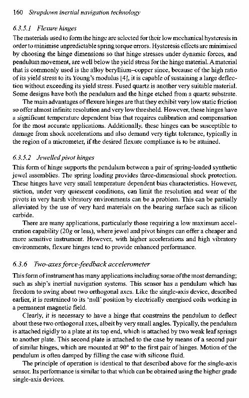
This form of hinge supports the pendulum between a pair of spring-loaded syntheticjewel assemblies. The spring loading provides three-dimensional shock protection.These hinges have very small temperature dependent bias characteristics. However,stiction, under very quiescent conditions, can limit the resolution and wear of thepivots in very harsh vibratory environments can be a problem. This can be partiallyalleviated by the use of very hard materials on the bearing surface such as siliconcarbide.
There are many applications, particularly those requiring a low maximum accel-eration capability (2Og or less), where jewel and pivot hinges can offer a cheaper andmore sensitive instrument. However, with higher accelerations and high vibratoryenvironments, flexure hinges tend to provide enhanced performance.
6.3.6 Two-axes force-feedback accelerometer
This form of instrument has many applications including some of the most demanding;such as ship's inertial navigation systems. This sensor has a pendulum which hasfreedom to swing about two orthogonal axes. Like the single-axis device, describedearlier, it is restrained to its 'null' position by electrically energised coils working ina permanent magnetic field.
Clearly, it is necessary to have a hinge that constrains the pendulum to deflectabout these two orthogonal axes, albeit by very small angles. Typically, the pendulumis attached rigidly to a plate at its top end, which is attached by two weak leaf springsto another plate. This second plate is attached to the case by means of a second pairof similar hinges, which are mounted at 90° to the first pair of hinges. Motion of thependulum is often damped by filling the case with silicone fluid.
The principle of operation is identical to that described above for the single-axissensor. Its performance is similar to that which can be obtained using the higher gradesingle-axis devices.
6.3.7 Open-loop accelerometers
A common form of this sensor is the mass-spring device of the type describedin Section 6.2. Generally, these instruments are less stable and less accurate thanthe closed loop accelerometers. Undesirable characteristics inherent in open-loopaccelerometers are sensitivity to supply voltage variations, non-linearity of thedisplacement caused by the applied acceleration and high thermal coefficients ofbias and scale-factor. Consequently, they are generally inappropriate for most inertialnavigation applications and therefore the mechanical variant will not be discussedfurther. Currently, however, an optical open-loop pendulous fibre optic accelero-meter is being developed and the principle of operation will be discussed in thefollowing section.
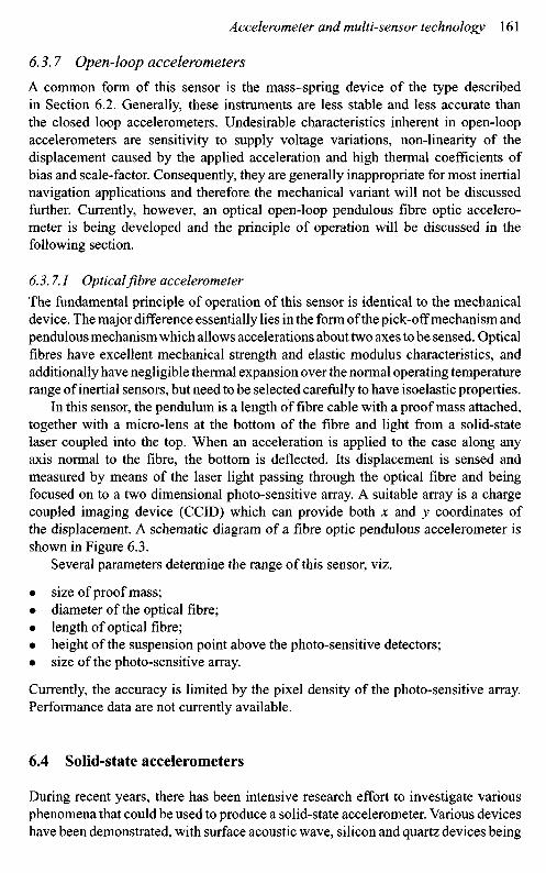
6.3.7.1 Optical fibre accelerometer
The fundamental principle of operation of this sensor is identical to the mechanicaldevice. The major difference essentially lies in the form of the pick-off mechanism andpendulous mechanism which allows accelerations about two axes to be sensed. Opticalfibres have excellent mechanical strength and elastic modulus characteristics, andadditionally have negligible thermal expansion over the normal operating temperaturerange of inertial sensors, but need to be selected carefully to have isoelastic properties.
In this sensor, the pendulum is a length of fibre cable with a proof mass attached,together with a micro-lens at the bottom of the fibre and light from a solid-statelaser coupled into the top. When an acceleration is applied to the case along anyaxis normal to the fibre, the bottom is deflected. Its displacement is sensed andmeasured by means of the laser light passing through the optical fibre and beingfocused on to a two dimensional photo-sensitive array. A suitable array is a chargecoupled imaging device (CCID) which can provide both x and y coordinates ofthe displacement. A schematic diagram of a fibre optic pendulous accelerometer isshown in Figure 6.3.
Several parameters determine the range of this sensor, viz.
• size of proof mass;• diameter of the optical fibre;• length of optical fibre;• height of the suspension point above the photo-sensitive detectors;• size of the photo-sensitive array.
Currently, the accuracy is limited by the pixel density of the photo-sensitive array.Performance data are not currently available.
6.4 Solid-state accelerometers
During recent years, there has been intensive research effort to investigate variousphenomena that could be used to produce a solid-state accelerometer. Various deviceshave been demonstrated, with surface acoustic wave, silicon and quartz devices being
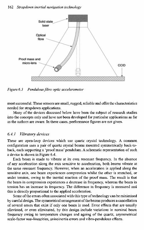
Figure 6.3 Pendulous fibre optic accelerometer
most successful. These sensors are small, rugged, reliable and offer the characteristicsneeded for strapdown applications.
Many of the devices discussed below have been the subject of research studiesinto the concepts only and have not been developed for particular applications as faras the authors are aware. In these cases, performance figures are not given.
6.4.1 Vibratory devices
These are open-loop devices which use quartz crystal technology. A commonconfiguration uses a pair of quartz crystal beams mounted symmetrically back-to-back, each supporting a 'proof mass' pendulum. A schematic representation of sucha device is shown in Figure 6.4.
Each beam is made to vibrate at its own resonant frequency. In the absenceof any acceleration along the axis sensitive to acceleration, both beams vibrate atthe same resonant frequency. However, when an acceleration is applied along thesensitive axis, one beam experiences compression whilst the other is stretched, orunder tension, owing to the inertial reaction of the proof mass. The result is thatthe beam in compression experiences a decrease in frequency, whereas the beam intension has an increase in frequency. The difference in frequency is measured andthis is directly proportional to the applied acceleration.
Some of the errors often associated with this type of technology can be minimisedby careful design. The symmetrical arrangement of the beams produces a cancellationof several errors that exist if only one beam is used. Error effects that are usuallyalleviated, or even eliminated, by this design include variations in nominal beamfrequency owing to temperature changes and ageing of the quartz, asymmetricalscale-factor non-linearities, anisoinertia errors and vibro-pendulous effects.
Solid statelaser
Opticalfibre -
Proof mass andmicro-lens
CCID

Flexurehinge
Case
Mountingsurface
Vibratingbeam
transducer
Flexurehinge
Figure 6.4 Vibrating beam accelerometer
Typical performance data are shown below:
Input rangeScale-factor stabilityScale-factor non-linearityBiasThresholdBandwidth
±200gMOOppm-0.05% of full scale~0.1-l milli-g<10micro-g> 100 Hz
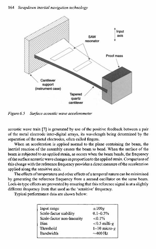
6.4.2 Surface acoustic wave accelerometer
This sensor is an open-loop instrument that has a surface acoustic wave resonatorelectrode pattern on the surface of a piezoelectric quartz cantilever beam [5,6]. Thisbeam is rigidly fixed at one end to the 'case' of the structure but is free to move at theother end, where a proof mass is rigidly attached, as shown in Figure 6.5. A surface
Inputaxis
Proofmass
Proofmass
Inputaxis
Cantileversupport
(instrument case)
Taperedquartz
cantilever
Figure 6.5 Surface acoustic wave accelerometer
acoustic wave train [7] is generated by use of the positive feedback between a pairof the metal electrode inter-digital arrays, its wavelength being determined by theseparation of the metal electrodes, often called fingers.
When an acceleration is applied normal to the plane containing the beam, theinertial reaction of the assembly causes the beam to bend. When the surface of thebeam is subjected to an applied strain, as occurs when the beam bends, the frequencyof the surface acoustic wave changes in proportion to the applied strain. Comparison ofthis change with the reference frequency provides a direct measure of the accelerationapplied along the sensitive axis.
The effects of temperature and other effects of a temporal nature can be minimisedby generating the reference frequency from a second oscillator on the same beam.Lock-in type effects are prevented by ensuring that this reference signal is at a slightlydifferent frequency from that used as the 'sensitive' frequency.
Typical performance data are shown below:
Input rangeScale-factor stabilityScale-factor non-linearityBiasThresholdBandwidth
±100#0.1-0.5%<0.1%<0.5 milli-gl-10micro-g-400Hz
SAWresonator
Proof mass

6.4.3 Silicon sensors
Over the last decade or so, there have been research studies directed to fabricatingaccelerometers from silicon [8, 9]. As a material, silicon has many advantages overother materials [ 10]. It is inexpensive, very elastic, non-magnetic, it has a high strengthto weight ratio and possesses excellent electrical properties allowing componentformation from diffusion or surface deposition. Additionally, it can be electricallyor chemically etched to very precise tolerances, of the order of micrometres.
In one concept, micro-machining techniques were used to form cantileveredbeams of silicon dioxide over shallow cavities etched in silicon. The end of thecantilever beam was gold plated to provide the proof mass and hence increase thesensitivity of the instrument. The cantilever was metal plated along its top surface toform one plate of a capacitor, the silicon substrate forming the other plate of thecapacitor, as illustrated in Figure 6.6. This form of accelerometer can be operated
Electrostaticforcer
electrode
Chip Inputaxis
Capacitivepick-off
Hinge
Proofmass
Electrostaticforcer
electrode
Figure 6.6 Silicon accelerometer

Inputaxis
Differentialcapacitance
pick-off
Silicondiaphragm
Differentialcapacitance
pick-off
Figure 6.7 Monolithic accelerometer
Cervitframe
in either an open-loop mode or as a closed loop device. In the open-loop mode,the capacitance between a pair of metal plates changes with the deflection of thecantilever, that is, the applied acceleration. In the closed loop mode, as shown inFigure 6.6, a pair of electrodes are used to null any deflections of the cantilever. Useof the closed loop mode increases its sensitivity. Although such devices tend not tobe very accurate, they are very small and quite rugged.
A monolithic accelerometer was developed in the United States during the early1980s. A cylindrical proof mass was supported by single crystal silicon diaphragmdiscs which were hinged on a cervit frame, as shown in Figure 6.7. This instru-ment was operated open-loop, using a differential capacitive pick-off on eachend to detect motion of the proof mass when subjected to an applied acceleration.The materials were chosen to provide a thermally stable path. The major problemareas with this instrument have centred around difficulties machining the materials,achieving adequate scale-factor linearity and bonding the components together.Currently, performance data are not available for this sensor.
Another form of silicon accelerometer that is currently under development hasfrequency sensitive resonant tie bars integrally attached to a silicon seismic mass.These tie bars are maintained at mechanical resonance, typically vibrating at frequen-cies between 40 and 100 kHz depending on the configuration. When an accelerationis applied along the sensitive axis, movement of the seismic mass induces a strainin the tie bars resulting in a change in frequency of the order of tens of hertz foreach applied unit g. This change in frequency is reasonably detectable. A conceptualdiagram of this sensor is shown in Figure 6.8.
Proofmass

Activeplate
Quartzresonator
Supportplate
Figure 6.8 Resonant silicon accelerometer
Typical performance parameters are:
Input rangeScale-factor stabilityScale-factor non-linearityBias (with compensation)ThresholdBandwidth
±100g0.5-2%0.1-0.4%<25milli-gl-10micro-g-400Hz
Work in the United Kingdom has investigated a thermal excitation methodas an alternative to the use of piezoelectric transducers for excitation of the proofmass. This thermal excitation technique is achieved by depositing a form of bimetallicstrip on the tie bars, which is used in place of the piezoelectric transducer.
A bimetallic element is formed on a tie bar by the deposition of a resistor on thetop surface of a tie bar. Application of a potential difference to this resistive loadproduces localised heating on the top surface of the tie bar. Consequently, there is anexpansion of the hot surface with respect to the cooler surface which causes the tie bar
Inputaxis
Supportplate
Proofmass
Quartzresonator

to bend. If an alternating potential is applied to this resistive load, then the localisedheating will be periodic and the top surface of the tie bar will expand and contract withrespect to the lower surface, depending on the heating cycle of the resistive material.The frequency of the applied current is chosen to be synchronous with one of thenatural resonant frequencies of the tie bars. As a result of this periodic bending of thetie bars, the proof mass is forced to oscillate as described above for the piezoelectricexcitation technique.
A second resistor is located on each of the driving tie bars and is used as a detectorto sense the oscillation frequency. This is then used as the feedback signal to modifythe frequency of the applied alternating current. The drive and control electronics canalso be formed in the silicon material. Quality factors in excess of 1000 have beendemonstrated with such designs.
Variation in the heating effect produced by the resistive material on the tie barsis achieved by applying a suitable bias in combination with the alternating drivecurrent. Consequently, the variation in the polarity of this applied potential allowsthe heating effect of the resistive material to be modulated at the frequency of thisapplied potential.
The main motivation for the development of this excitation technique was thatan all silicon sensor could be developed. Several techniques exist for the depositionof the resistive heating elements on to the tie bars. Examples include direct diffusiondoping or polysilicon deposition. Similar techniques can be used to form the detector.
6.4.4 Fibre optic accelerometer
The use of fibre optical elements is very attractive for many applications as the fibreoptical waveguide is immune to electromagnetic interference. One form of fibre opticsensor has already been described, as it is very similar in operation to the pendulousaccelerometers; the fibre optics merely providing an alternative form of readout. Otherforms of fibre optic accelerometer rely on some physical change in a component whichcan be sensed using electromagnetic radiation.
Ensuring that these changes are linear functions of acceleration in knowndirections remains a difficult development problem, although the use of fibretechnologies gives a very sensitive position readout.
6.4.4.1 Mach-Zehnder interferometric accelerometer
A Mach-Zehnder interferometer [11] uses either one or two optical fibres attachedto an inertial mass as its sensitive element. When an acceleration is applied alongthe axis of the optical fibre, this will produce a small change in length which isproportional to the applied acceleration. The change in length can be detected byinterferometric techniques similar to those described for the fibre optic gyroscope.The use of two optical fibres allows each fibre to form an arm of the interferometerand the use of nulling techniques enables greater sensitivity to be achieved, alongwith compensation for temperature changes in the fibres. Additionally, it is necessaryto constrain the proof mass to move only along the sensitive axis of the instrument.

Proofmass
Opticalfibre
Opticalfibre
Single-fibreconfiguration
Two-fibreconfiguration
Figure 6.9 Sensitive elements of a Mach-Zehnder interferometric accelerometer
Schematic illustrations of the sensitive elements of two possible configurationsare shown in Figure 6.9.
A very sensitive sensing element for accelerometers can be produced by windinga fibre optic coil around a compliant former, such as a rubber cylinder. When an accel-eration is applied to the sensing element it changes dimensions and hence producesa phase change in the interferometer which is proportional to the applied accelera-tion. The sensitivity of the device is proportional to the number of optical fibre turnson the cylinder. Maximum sensitivity can be achieved by operating the device in afeedback mode, as shown in Figure 6.10. The intensities of the two light beams inthe interferometer are detected separately and compared in a differential amplifier.The output signal from this component can then be used to 'drive' a piezoelectricdevice to null the phase change introduced by the distortion of the sensing element.The output of the differential amplifier is proportional to the applied acceleration.Again, it is necessary to constrain the movement of the element to be only alongthe sensitive axis of the device. Other technological concerns are the longer termstability of the compliant component and the effect of the different thermal expansioncoefficients.
6.4.4.2 Vibrating fibre optic accelerometer
A short length of single mode optical fibre is fastened and tensioned between twopivot points in a rigid structure. This structure is vibrated so that the optical fibreoscillates at its fundamental frequency. In the absence of any applied acceleration,the displacements are symmetrical and the maximum stretch occurs at the maxi-mum displacement with relaxation as it passes the centre line. Light passing throughthis optical fibre is phase modulated at 2 / , and at higher-order even harmonicsof / , where / is the fundamental frequency. However, when the sensitive elementis subjected to an acceleration parallel to the plane containing the oscillation, thedisplacement of the fibre will now be asymmetrical.
Inputaxis
Proofmass

Beam splitter
Opticalfibre
Elasticcylinder
Case
Mirror
Photodetector
Piezoelectricmaterial
Compensator
Figure 6.10 Interference accelerometer
Fibresupportframe Optical fibre
Fibresupportframe
Vibratingplatform
Case Vibratingplatform
(a) No applied acceleration(symmetrical deflection)
(b) Applied acceleration(asymmetrical deflection)
Figure 6.11 Oscillating modes of a vibrating fibre accelerometer
Light passing through the optical fibre will now be phase modulated at / and at theodd harmonics of / . The first and odd harmonic phase modulation has an amplitudeproportional to the applied acceleration, and its phase relative to the drive signal willdepend on the sense of the applied acceleration. Again, fibre optic interferometrictechniques are used to sense the phase changes. Care is necessary in the choice offundamental frequency and the design to reduce the effects of orthogonal accelerationsensitivities and environmental vibratory motion. The displacement of the fibre isshown schematically under the conditions of no acceleration and applied accelerationin Figure 6.11.
It may be possible to produce an amplitude modulation system by using 'lossy'multi-mode optical fibre, which is optimised for micro-bending losses, describedin Figure 6.11. In this case, light which is guided along the vibrating optical
Lasersource Input
axis

Gradedindexrod
Quarterwave
Polariser p l a t ePhotoelastic
material
Opticalfibre Detector
Figure 6.12 Photo-elastic accelerometer
fibre, is coupled into the cladding surrounding the optical core at the supportpoints. This occurs as a consequence of the bending of the fibre decreasing thebarrier between the core and cladding modes. Such a system would not need touse interferometry to determine the magnitude of the applied acceleration. This isbecause this technique converts the device from a phase modulator to an amplitudemodulator.
6.4.4.3 Photo-elastic fibre optic accelerometers
The sensitive element in this device is a birefringent material [H]. Suitably polarisedlight is coupled into the sensitive element using multi-mode optical fibre. When anacceleration is applied to the photo-elastic material the transmission of light throughit changes and the change is proportional to the applied acceleration. Research iscontinuing with this form of sensor. A schematic diagram of an engineering conceptis shown in Figure 6.12.
6.4.4.4 Bragg grating fibre accelerometer
Research work in the United States and in Europe, at the Microelectronic Centreof Denmark, has demonstrated an accelerometer containing a Bragg grating in anoptical waveguide. The centre wavelength of a Bragg grating is determined by thecharacteristics of the grating but can be changed by changes in the temperature, strainand pressure applied to the grating [12, 13]. Thus, an optical waveguide containinga Bragg grating is distorted when an acceleration is applied along the waveguide,the wavelength of light transmitted along the waveguide changes. This change inwavelength is proportional to the applied acceleration. The change is small but canbe detected using a fibre interferometer [14].
The effect of the applied acceleration can be enhanced if the fibre waveguideis rigidly bonded to a proof mass. The general layout of this sensor is shown inthe schematic diagram in Figure 6.13a. Care is necessary to ensure that the proofmass and fibre move in the direction of the applied acceleration and do not deflect
Proofmass
Inputaxis
Analyser
Case
Source

(a) Supportframe
Inputaxis
Opticalfibre
(b)Input axis
Bragggrating
Opticalfibre
Supportframe
Proofmass
Figure 6.13 Bragg grating fibre(b) Section view
accelerometer. (a) Schematic layout.
when cross-axis accelerations are applied. This is accomplished using 'guides' asshown in Figure 6.13b. Clearly, care is necessary to ensure that movement of theproof mass is not impeded by these 'guides'. Performance data are not available,but initial measurements suggest sensitivities of these devices to be in the micro-gregime.
6.4.4.5 Combined fibre optic sensors
The use of similar materials such as solid-state lasers, photo-detectors, optical fibresand common techniques in the fabrication of the sensors, suggests that there is plentyof scope for producing integrated devices, enabling both angular rate and linearacceleration to be sensed in a single device. The operation of the individual aspectsof each sensor has already been dealt with in each appropriate section and will notbe repeated here. The major problems are associated with the integration of the
Bragggrating
Proofmass
Proofmassguide
Proofmassguide

individual components and the sharing of components. Additionally, it is necessaryto isolate particular processes, such as modulation frequencies, in order that effectscan be identified uniquely.
6.4.5 Optical accelerometers
It appears that there have been relatively small developments in this class of sensor.The value of optical readout techniques is well recognised, particularly with respect toenhanced sensitivity leading to greater resolution and accuracy. This class of devicemay provide resolution in the nano-g range and be valuable for detecting seismicdisturbances or gravity gradients, but of course other features of the accelerometermust be compatible with this aspect of performance, particularly the noise in theoutput signal. This class of performance is comparable with the MEMS tunnellingdevices (Section 7.4.4), and so may compete for similar applications.
There is some continuing research involving fibre optical accelerometers andfibre Bragg devices; the physical principles of these devices are reviewed inSection 6.4.4.
Measurement of applied acceleration has been demonstrated using opticalmicro-spheres. In this case the light coupled into an optically resonant micro-spherechanges as the sphere moves towards a waveguide.
6.4.6 Other acceleration sensors
Many physical effects have been exploited over the last half century or more in anattempt to measure acceleration. For completeness, two other interesting conceptsknown to the authors are discussed below. Generally, these programmes are notactive, but either or both could become active if there is a significant change in arelevant technology.
6.4.6.1 Solid-state ferroelectric accelerometer
Attempts have been made to use the piezo-optic and dielectric properties offerromagnetic materials. It was hoped to measure the magnitude of the applied accel-eration as a function of the strain or pressure induced in a thin fibre of this material.However, technological limitations in the past prevented the feasibility of the devicebeing demonstrated.
6.4.6.2 Solution electrolytic accelerometer
This is a solid-state ion device, making use of a shift in ions in a solution owingto the application of an acceleration. This motion causes a resultant change in thepotential in the electrolyte and this potential change was found to be proportionalto the applied acceleration, with good linearity. However, the electrolyte is, by itsvery nature thermally sensitive. This device was originally developed as part of theGerman missile programme during World War II.
Next Page