STRAPDOWN INERTIAL NAVIGATION SYSTEMS BASED ON … · 2019-02-27 · strapdown inertial navigation...
9
STRAPDOWN INERTIAL NAVIGATION SYSTEMS BASED ON FIBER OPTIC GYROSCOPES Yu.N.Korkishko 1 , V.A.Fedorov 2 , V.E.Prilutskiy 3 , V.G.Ponomarev 4 , I.V.Morev 5 , S.F.Skripnikov 6 , M.I.Khmelevskaya 7 , A.S.Buravlev 8 , S.M.Kostritskiy 9 , A.I.Zuev 10 , V.K.Varnakov 11 Optolink RPC LLC, 124489, Moscow, Zelenograd, Sosnovaya alleya, Building 6A, Str.2 Russia, Tel: +7 495 6631760, Fax: +7 495 6631761, e-mail: [email protected] Abstract Key words: strapdown inertial navigation systems, fiber-optic gyroscopes At present time fiber-optic gyroscopes (FOGs) with closed-loop feedback scheme of operation are becoming widely used in inertial navigation systems. In the current work the series of devices developed and produced by LLC RPC “Optolink” are discussed. The first group is single-axis fiber-optic gyroscopes (FOGs) with different fiber length and fiber coil diameter: SRS-2000, SRS-1000, SRS-501, SRS-200. The second group comprises three-axis devices (TRS) and inertial measurement units (IMUs): TRS-500, IMU-500, IMU-501. All FOGs are producted in a so-called “minimal” configuration. The major components of FOGs and their impact on FOGs accuracy characteristics are discussed. Introduction Strapdown inertial navigation systems (SINS) have become the base of navigation complexes in modern vehicles. This fact is because SINSs have comprehensive data output that consists of navigation parameters of movement – heading, roll and pitch angles, acceleration parameters, velocity and vehicle coordinates. In addition, they are fully autonomous, and require minimal external information for the operation. Owing to the ability to identify the angular position of an object with high accuracy within any range of angles and with high output rate, at present time SINS have no alternatives. For the time being, SINS based on fiber-optic gyroscopes (FOGs) with closed-loop scheme of operation are becoming widely used in inertial navigation complexes. In this work the development of SINS produced by LLC RPC Optolink – SINS-500K, SINS-500M and SINS-501 is discussed. These systems are based on fiber-optic sensors of own manufacturing. Test results for the systems in different areas of applications are also presented. Fiber-optic gyroscopes All FOGs produced by LLC RPC “Optolink” are made in co-called minimum configuration with digital signal processing (DSP). Minimum configuration ensures the reciprocity of optical paths for two beams counter- propagating in a fiber loop. Sctructural scheme of single-axis and three-axis FOGs with DSP is represented in Fig.s 1 and 2, respectively. FOGs consist of one light source with central wavelength 1550 nm, one or three photodetectors, one or two fiber splitters (1:1 and 1:2) to divide the light wave into two parts, one or three ring interferometers to sense orthogonal angular rates, and signal processing circuits. Ring interferometer consists of a multifunction integrated optic chip (MIOC) and polarization maintaining (PM) fiber coil with the length of 200, 500 1000 and 2000 meters, also produced by Optolink. The MIOC is a three-port integrated optical chip fabricated at lithium niobate wafer which executes three functions [3]. In TRS-500 (and IMU-500) devices only one light source for three channels is used. The use of three photodiodes provides the ability to simultaneously handle the signal processing of three channels with independent DSPs. Each DSP generates voltage for “sawtooth” light modulation in order to compensate Sagnac phase shift and to make fixed phase shift π/2 between counter- propagating waves using additional modulation. As a result, each channel is operating in closed-loop regime [4- 8, 12-14]. 1 Doctor of Physics and Mathematics, Professor, General Director. 2 Doctor of Physics and Mathematics, Professor, Technical Director. 3 Director of Saratov branch. 4 Candidate of Technical Sciences, Chief Designer, Technical Director of Saratov branch. 5 Principal Engineer. 6 Principal Engineer. 7 Principal Engineer. 8 Principal Engineer. 9 Doctor of Physics and Mathematics, Associated Professor, Technical Director of Zelenograd branch. 10 Director of Arzamas branch. 11 Technical Director of Arzamas branch. 97
Transcript of STRAPDOWN INERTIAL NAVIGATION SYSTEMS BASED ON … · 2019-02-27 · strapdown inertial navigation...
STRAPDOWN INERTIAL NAVIGATION SYSTEMS BASED ON FIBER OPTIC GYROSCOPES
Yu.N.Korkishko 1, V.A.Fedorov2, V.E.Prilutskiy3, V.G.Ponomarev4, I.V.Morev5, S.F.Skripnikov6, M.I.Khmelevskaya7, A.S.Buravlev8, S.M.Kostritskiy9, A.I.Zuev10, V.K.Varnakov11
Optolink RPC LLC, 124489, Moscow, Zelenograd, Sosnovaya alleya, Building 6A, Str.2 Russia, Tel: +7 495 6631760, Fax: +7 495 6631761, e-mail: [email protected]
Abstract
Key words: strapdown inertial navigation systems, fiber-optic gyroscopes
At present time fiber-optic gyroscopes (FOGs) with closed-loop feedback scheme of operation are becoming widely used in inertial navigation systems. In the current work the series of devices developed and produced by LLC RPC “Optolink” are discussed. The first group is single-axis fiber-optic gyroscopes (FOGs) with different fiber length and fiber coil diameter: SRS-2000, SRS-1000, SRS-501, SRS-200. The second group comprises three-axis devices (TRS) and inertial measurement units (IMUs): TRS-500, IMU-500, IMU-501. All FOGs are producted in a so-called “minimal” configuration. The major components of FOGs and their impact on FOGs accuracy characteristics are discussed.
Introduction
Strapdown inertial navigation systems (SINS) have become the base of navigation complexes in modern vehicles. This fact is because SINSs have comprehensive data output that consists of navigation parameters of movement – heading, roll and pitch angles, acceleration parameters, velocity and vehicle coordinates. In addition, they are fully autonomous, and require minimal external information for the operation. Owing to the ability to identify the angular position of an object with high accuracy within any range of angles and with high output rate, at present time SINS have no alternatives. For the time being, SINS based on fiber-optic gyroscopes (FOGs) with closed-loop scheme of operation are becoming widely used in inertial navigation complexes.
In this work the development of SINS produced by LLC RPC Optolink – SINS-500K, SINS-500M and SINS-501 is discussed. These systems are based on fiber-optic sensors of own manufacturing. Test results for the systems in different areas of applications are also presented. Fiber-optic gyroscopes
All FOGs produced by LLC RPC “Optolink” are made in co-called minimum configuration with digital
signal processing (DSP). Minimum configuration ensures the reciprocity of optical paths for two beams counter-propagating in a fiber loop.
Sctructural scheme of single-axis and three-axis FOGs with DSP is represented in Fig.s 1 and 2, respectively. FOGs consist of one light source with central wavelength 1550 nm, one or three photodetectors, one or two fiber splitters (1:1 and 1:2) to divide the light wave into two parts, one or three ring interferometers to sense orthogonal angular rates, and signal processing circuits. Ring interferometer consists of a multifunction integrated optic chip (MIOC) and polarization maintaining (PM) fiber coil with the length of 200, 500 1000 and 2000 meters, also produced by Optolink. The MIOC is a three-port integrated optical chip fabricated at lithium niobate wafer which executes three functions [3]. In TRS-500 (and IMU-500) devices only one light source for three channels is used. The use of three photodiodes provides the ability to simultaneously handle the signal processing of three channels with independent DSPs. Each DSP generates voltage for “sawtooth” light modulation in order to compensate Sagnac phase shift and to make fixed phase shift π/2 between counter-propagating waves using additional modulation. As a result, each channel is operating in closed-loop regime [4-8, 12-14].
1 Doctor of Physics and Mathematics, Professor, General Director. 2 Doctor of Physics and Mathematics, Professor, Technical Director. 3 Director of Saratov branch. 4 Candidate of Technical Sciences, Chief Designer, Technical Director of Saratov branch. 5 Principal Engineer. 6 Principal Engineer. 7 Principal Engineer. 8 Principal Engineer. 9 Doctor of Physics and Mathematics, Associated Professor, Technical Director of Zelenograd branch. 10 Director of Arzamas branch. 11 Technical Director of Arzamas branch.
97

Fig. 1. Configuration of FOG SRS-1000: SLD – light source, superluminescent light emitting diode; DP – depolarizer;
MIOC – multifunctional integrated optic chip; RS-485 – serial interface
DSP1RS485
DPSLD
PD1
PD2
PD3
FS :2)(1
FS :1)(1 FS :1)(1
FS :1)(1
FS :1)(1
DSP2
DSP3
MIOC 3-
MIOC-2
MIOC 1-
PM fiber coil 1
PM fiber coil 2
PM fiber coil 3
Fig. 2. Configuration of FOG TRS-500 SLD – light source, superluminescent light emitting diode; DP – depolarizes; FS – fiber splitter; PD – photodetector; MIOC –
multifunctional integrated optic chip; DSP – digital signal processor; RS-485 – serial interface.
At present time LLC RPC “Optolink” has developed and produces a series of single-axis FOGs - SRS-2000, SRS-1000, SRS-501 and SRS-200 with the difference in fiber coil length and diameter, and series of three-axis FOG TRS-500 and inertial measurement units (IMUs) IMU-500 and IMU-501 [4-8, 12-14]. Accuracy and operational characteristics of these devices are represented in Table 1.
T a b l e 1
FOGs produced by LLC RPC “Optolink” accuracy and operational characteristics
Parameter Single axis SRS-2000
Single axis SRS-1000
Single axis SRS-501
Three axis TRS-500
Single axis SRS-200
Three axis VOBIS
(Space Grade)
Range of measured angular rate, deg/sec 40 90 250 300 800 30
Bias drift at fixed temperature, deg/h
0.005 0.01 0.1 0.1 0.2 0.03
Scale factor repeatability, ppm
100 200 500 700 1000 500
Bandwidth, Hz: 50 100 300 300 400 100
Random walk, deg/√h 0.0003 0.0005 0.003 0.01 0.02 0.001
Weight, kg 1.1 0.8 0.35 1.2 0.22 2.6
Dimensions, mm: Ø 250x80 Ø150x80 Ø100x30 110x110x90 Ø70x28 172х176х110
Output signal RS485/RS422
98
Strapdown inertial navigation systems
Strapdown inertial navigation systems SINS-500 (SINS-500K, SINS-500M) and SINS-501 are used for the piloting-navigation data output to its receiver in autonomous (inertial) mode as well as in the GPS integration mode. Systems SINS-500K and SINS-500M are based on inertial measurement unit (IMU) IMU-500, which consists of three-axis FOG TRS-500 produced by Optolink company and three orthogonally mounted accelerometers by other manufacturers (AT-1104, INN-203 or others on customer’s demand). Digital data output is held via RS-422 (optionally, RS-485, MIL-STD-1553B) and others on customer’s demand. FOGs (IMU) operation process (SLD operation modes, photodetectors signal processing, phase modulation control) is performed by the FOGs (IMU) block of service boards. Analog signals, proportional to the value of acceleration on orthogonal axes, from three accelerometers are transferred to the three channels of 24-byte analog-digital converter. Signal from the temperature sensor is sent to the 4-th channel of AD converter. Interface block processor handles the data from all angular rate sensors, acceleration and temperature sensors, and sends it via exchange serial channel to the computer. System computer serves the purpose of autonomous alignment, orientation and navigation. Computer block is connected to the external device via serial interface and sends to the inquirer the information about angular position, coordinates, velocities of an object, and receives the input data from it.
Satellite receiver (1К-161) transfers to the system computer the correction data about the coordinates and velocity of an object via the serial channel in case that the satellites of GLONASS and NAVSTAR system are in view. In case of reliable information from the satellite, the computer corrects the INS with it. In case of no signal from the satellite, the system sends the data and operates in autonomous inertial mode [9-11].
Strapdown inertial navigation system SINS-500K
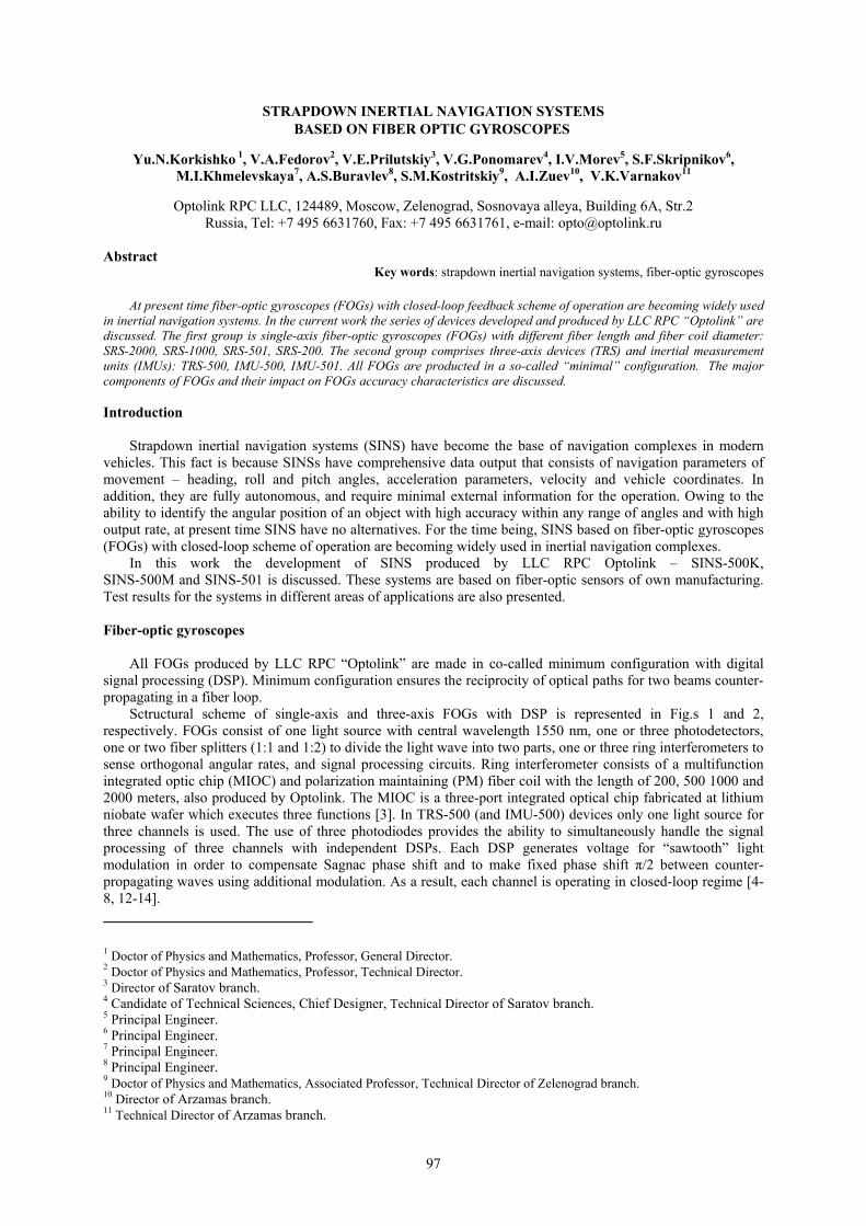
External view and internal structure of SINS-500K are shown in Fig. 3.
Fig. 3. External view and internal structure of SINS-500K system
SINS operation sequence diagram includes the following stages: SINS coarse initial alignment;
SINS precise initial alignment;
SINS navigation mode.
At the stage of the SINS coarse initial alignment rough estimation of IMU angular orientation is performed according to IMU output data.
At the stage of precise initial alignment the SINS-500K (realization of alignment in static conditions) estimates the errors and tolerances of IMU angular orientation, residual drifts of MUs and parameters of their dynamic models. This task is solved using the method of analytical gyrocompassing with Kalman filtration post-processing.
99
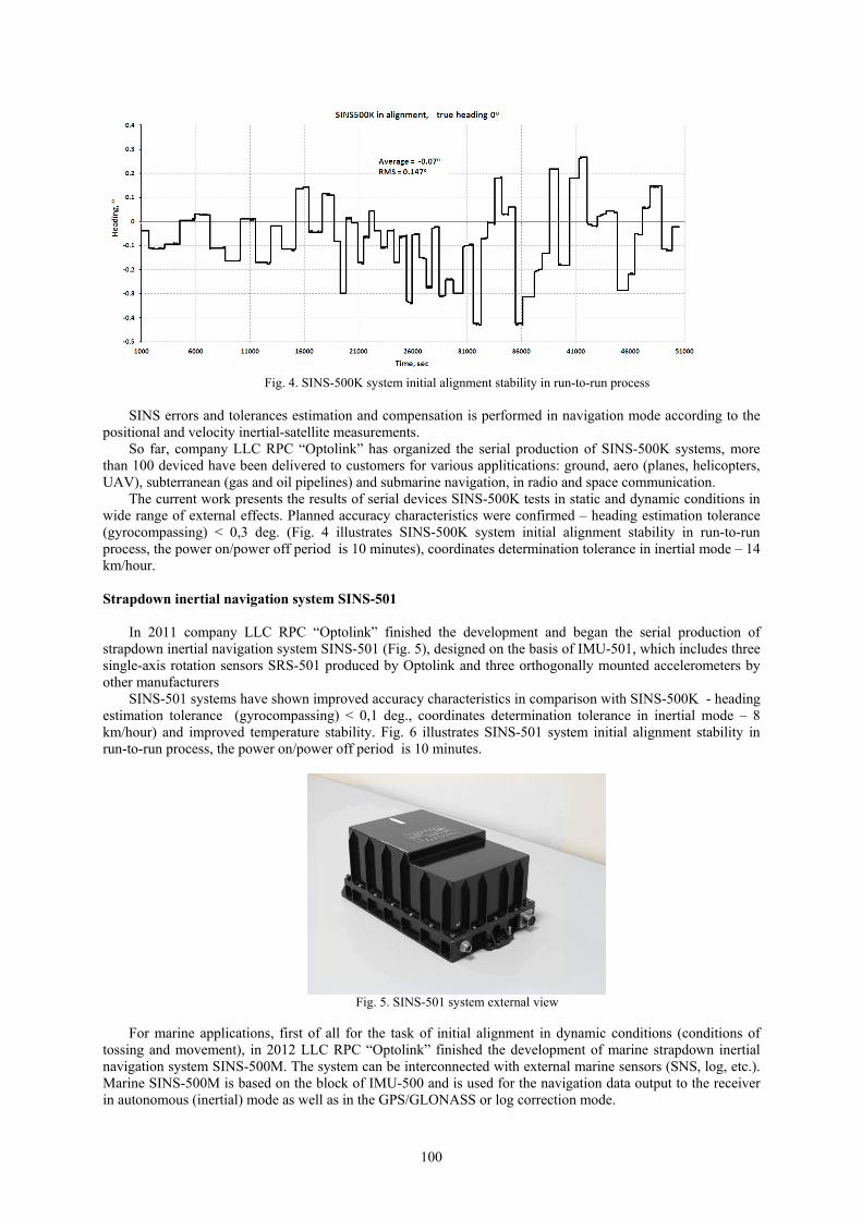
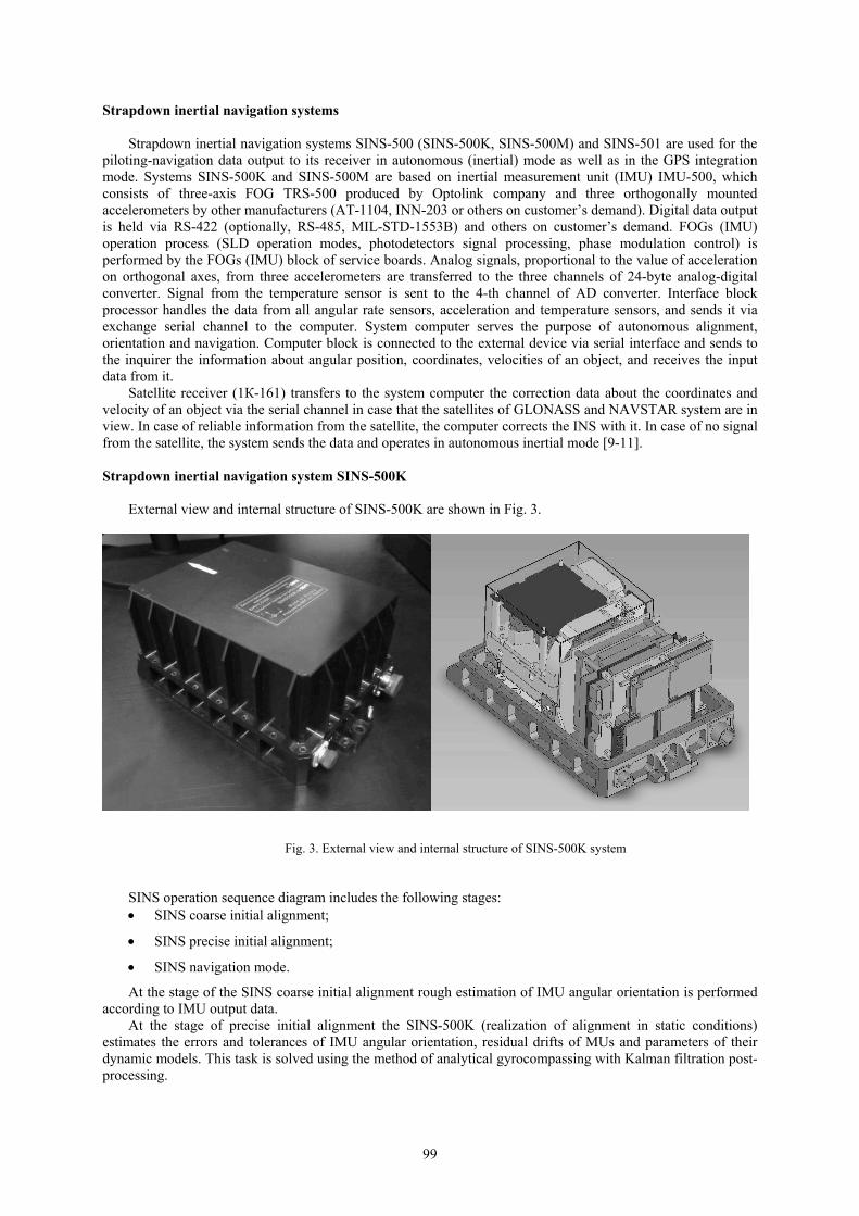
Fig. 4. SINS-500K system initial alignment stability in run-to-run process
SINS errors and tolerances estimation and compensation is performed in navigation mode according to the
positional and velocity inertial-satellite measurements. So far, company LLC RPC “Optolink” has organized the serial production of SINS-500K systems, more
than 100 deviced have been delivered to customers for various applitications: ground, aero (planes, helicopters, UAV), subterranean (gas and oil pipelines) and submarine navigation, in radio and space communication.
The current work presents the results of serial devices SINS-500K tests in static and dynamic conditions in wide range of external effects. Planned accuracy characteristics were confirmed – heading estimation tolerance (gyrocompassing) < 0,3 deg. (Fig. 4 illustrates SINS-500K system initial alignment stability in run-to-run process, the power on/power off period is 10 minutes), coordinates determination tolerance in inertial mode – 14 km/hour. Strapdown inertial navigation system SINS-501
In 2011 company LLC RPC “Optolink” finished the development and began the serial production of
strapdown inertial navigation system SINS-501 (Fig. 5), designed on the basis of IMU-501, which includes three single-axis rotation sensors SRS-501 produced by Optolink and three orthogonally mounted accelerometers by other manufacturers
SINS-501 systems have shown improved accuracy characteristics in comparison with SINS-500K - heading estimation tolerance (gyrocompassing) < 0,1 deg., coordinates determination tolerance in inertial mode – 8 km/hour) and improved temperature stability. Fig. 6 illustrates SINS-501 system initial alignment stability in run-to-run process, the power on/power off period is 10 minutes.
Fig. 5. SINS-501 system external view
For marine applications, first of all for the task of initial alignment in dynamic conditions (conditions of
tossing and movement), in 2012 LLC RPC “Optolink” finished the development of marine strapdown inertial navigation system SINS-500M. The system can be interconnected with external marine sensors (SNS, log, etc.). Marine SINS-500M is based on the block of IMU-500 and is used for the navigation data output to the receiver in autonomous (inertial) mode as well as in the GPS/GLONASS or log correction mode.
100
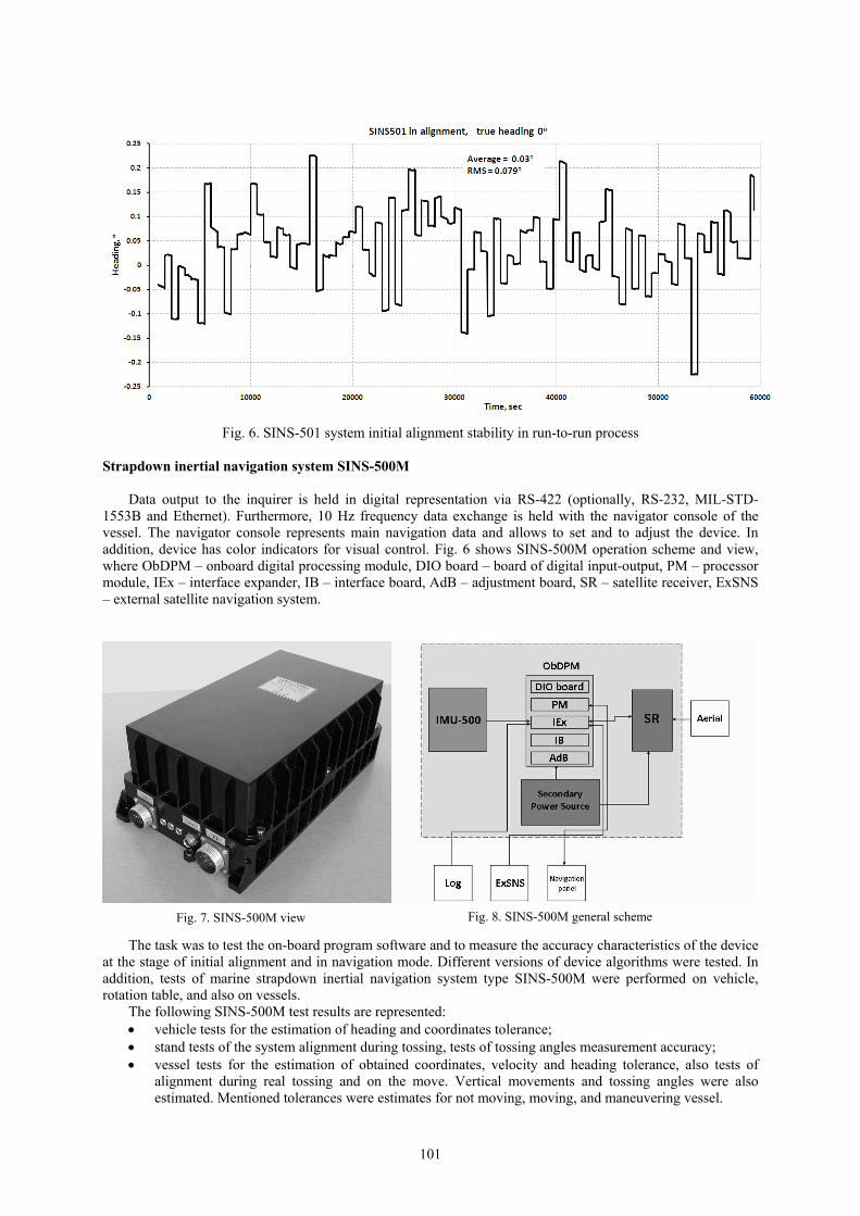
Fig. 6. SINS-501 system initial alignment stability in run-to-run process
Strapdown inertial navigation system SINS-500M
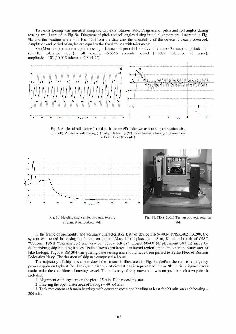
Data output to the inquirer is held in digital representation via RS-422 (optionally, RS-232, MIL-STD-
1553B and Ethernet). Furthermore, 10 Hz frequency data exchange is held with the navigator console of the vessel. The navigator console represents main navigation data and allows to set and to adjust the device. In addition, device has color indicators for visual control. Fig. 6 shows SINS-500M operation scheme and view, where ObDPM – onboard digital processing module, DIO board – board of digital input-output, PM – processor module, IEx – interface expander, IB – interface board, AdB – adjustment board, SR – satellite receiver, ExSNS – external satellite navigation system.
Fig. 8. SINS-500M general scheme Fig. 7. SINS-500M view
The task was to test the on-board program software and to measure the accuracy characteristics of the device at the stage of initial alignment and in navigation mode. Different versions of device algorithms were tested. In addition, tests of marine strapdown inertial navigation system type SINS-500M were performed on vehicle, rotation table, and also on vessels.
The following SINS-500M test results are represented: vehicle tests for the estimation of heading and coordinates tolerance; stand tests of the system alignment during tossing, tests of tossing angles measurement accuracy; vessel tests for the estimation of obtained coordinates, velocity and heading tolerance, also tests of
alignment during real tossing and on the move. Vertical movements and tossing angles were also estimated. Mentioned tolerances were estimates for not moving, moving, and maneuvering vessel.
101
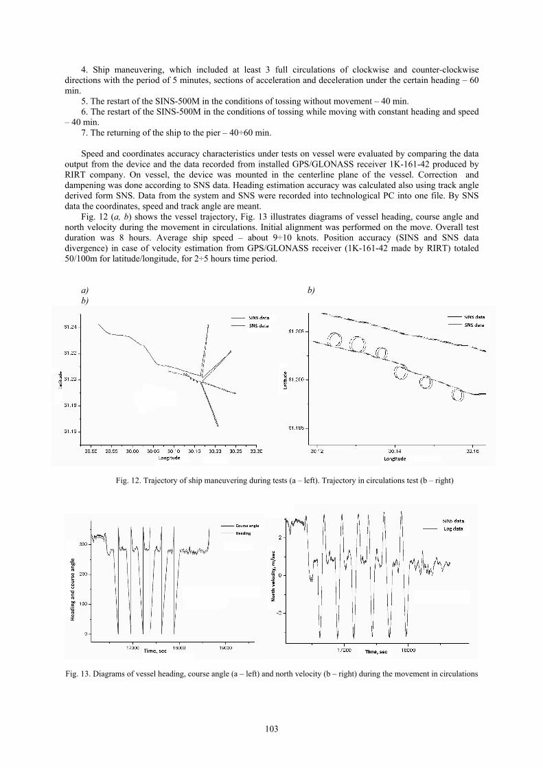
Two-axis tossing was imitated using the two-axis rotation table. Diagrams of pitch and roll angles during tossing are illustrated in Fig. 9a. Diagrams of pitch and roll angles during initial alignment are illustrated in Fig. 9b, and the heading angle – in Fig. 10. From the diagrams the operability of the device is clearly observed. Amplitude and period of angles are equal to the fixed values with tolerances:
Set (Measured) parameters: pitch tossing – 10 seconds period (10.00299, tolerance ~3 msec), amplitude – 7° (6.9918, tolerance ~0,5´); roll tossing –6.6666 seconds period (6.6687, tolerance ~2 msec), amplitude – 10° (10,015,tolerance 0,6´÷1,2´).
Fig. 9. Angles of roll tossing (�) and pitch tossing (Ψ) under two-axis tossing on rotation table (а - left). Angles of roll tossing (�) and pitch tossing (Ψ) under two-axis tossing alignment on
rotation table (b - right)
Fig. 10. Heading angle under two-axis tossing alignment on rotation table
Fig. 11. SINS-500M Test on two-axis rotation table
In the frame of operability and accuracy characteristics tests of device SINS-500M PNSK.402113.208, the system was tested in tossing conditions on cutter “Akustik” (displacement 18 tn, Karelian branch of OJSC “Concern TSNII “Okeanpribor) and also on tugboat RB-394 project 90600 (displacement 304 tn) made by St.Petersburg ship-building factory “Pella” (town Otradnoye, Leningrad region) on the move in the water area of lake Ladoga. Tugboat RB-394 was passing state testing and should have been passed to Baltic Fleet of Russian Federation Navy. The duration of ship use comprised 4 hours.
The trajectory of ship movement down the stream is illustrated in Fig. 9a (before the turn to emergency power supply on tugboat for check), and diagram of circulations is represented in Fig. 9b. Initial alignment was made under the conditions of moving vessel. The trajectory of ship movement was mapped in such a way that it included:
1. Alignment of the system on the pier - 15 min. Data recording start. 2. Entering the open water area of Ladoga – 40÷60 min. 3. Tack movement at 8 main bearings with constant speed and heading at least for 20 min. on each bearing –
200 min.
102
4. Ship maneuvering, which included at least 3 full circulations of clockwise and counter-clockwise directions with the period of 5 minutes, sections of acceleration and deceleration under the certain heading – 60 min.
5. The restart of the SINS-500M in the conditions of tossing without movement – 40 min. 6. The restart of the SINS-500M in the conditions of tossing while moving with constant heading and speed
– 40 min. 7. The returning of the ship to the pier – 40÷60 min.
Speed and coordinates accuracy characteristics under tests on vessel were evaluated by comparing the data
output from the device and the data recorded from installed GPS/GLONASS receiver 1K-161-42 produced by RIRT company. On vessel, the device was mounted in the centerline plane of the vessel. Correction and dampening was done according to SNS data. Heading estimation accuracy was calculated also using track angle derived form SNS. Data from the system and SNS were recorded into technological PC into one file. By SNS data the coordinates, speed and track angle are meant.
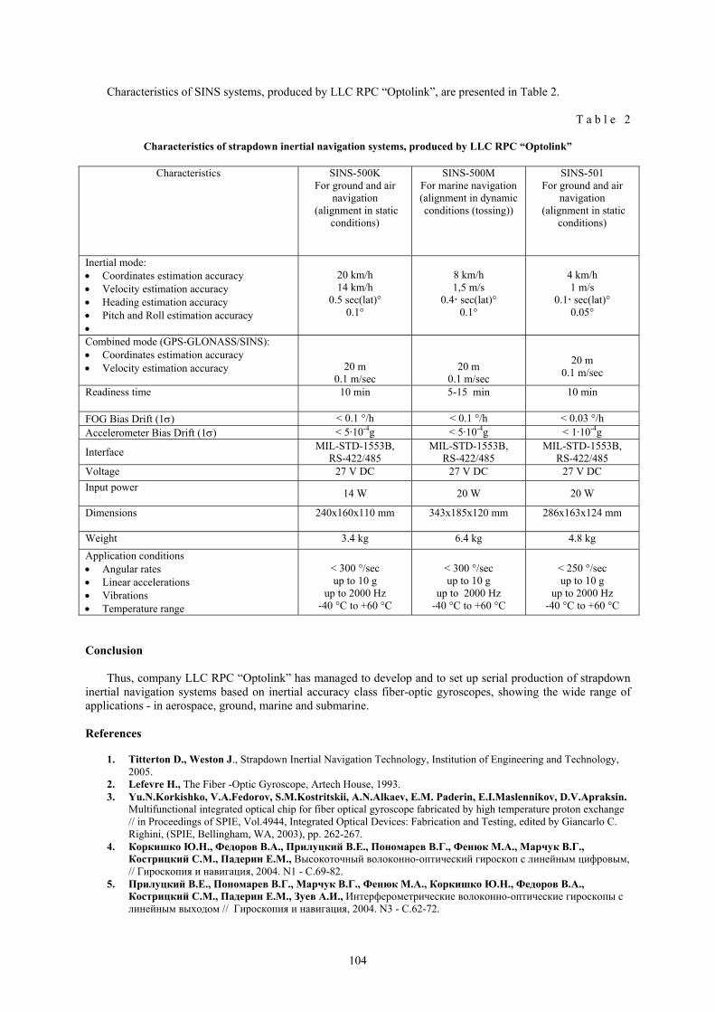
Fig. 12 (a, b) shows the vessel trajectory, Fig. 13 illustrates diagrams of vessel heading, course angle and north velocity during the movement in circulations. Initial alignment was performed on the move. Overall test duration was 8 hours. Average ship speed – about 9÷10 knots. Position accuracy (SINS and SNS data divergence) in case of velocity estimation from GPS/GLONASS receiver (1K-161-42 made by RIRT) totaled 50/100m for latitude/longitude, for 2÷5 hours time period.
a) b) b)
Fig. 12. Trajectory of ship maneuvering during tests (a – left). Trajectory in circulations test (b – right)
Fig. 13. Diagrams of vessel heading, course angle (a – left) and north velocity (b – right) during the movement in circulations
103
Characteristics of SINS systems, produced by LLC RPC “Optolink”, are presented in Table 2.
T a b l e 2
Characteristics of strapdown inertial navigation systems, produced by LLC RPC “Optolink”
Characteristics SINS-500K For ground and air
navigation (alignment in static
conditions)
SINS-500M For marine navigation (alignment in dynamic conditions (tossing))
SINS-501 For ground and air
navigation (alignment in static
conditions)
Inertial mode: Coordinates estimation accuracy Velocity estimation accuracy Heading estimation accuracy Pitch and Roll estimation accuracy
20 km/h 14 km/h
0.5 sec(lat)° 0.1°
8 km/h 1,5 m/s
0.4 sec(lat)° 0.1°
4 km/h 1 m/s
0.1 sec(lat)° 0.05°
Combined mode (GPS-GLONASS/SINS): Coordinates estimation accuracy Velocity estimation accuracy
20 m 0.1 m/sec
20 m 0.1 m/sec
20 m
0.1 m/sec
Readiness time 10 min 5-15 min 10 min
FOG Bias Drift (1) < 0.1 °/h < 0.1 °/h < 0.03 °/h Accelerometer Bias Drift (1) < 5·10-4g < 5·10-4g < 1·10-4g
Interface MIL-STD-1553B,
RS-422/485 MIL-STD-1553B,
RS-422/485 MIL-STD-1553B,
RS-422/485 Voltage 27 V DC 27 V DC 27 V DC
Input power
14 W 20 W 20 W
Dimensions
240x160x110 mm 343x185x120 mm 286x163x124 mm
Weight 3.4 kg 6.4 kg 4.8 kg
Application conditions Angular rates Linear accelerations Vibrations Temperature range
< 300 °/sec up to 10 g
up to 2000 Hz -40 °C to +60 °C
< 300 °/sec up to 10 g
up to 2000 Hz -40 °C to +60 °C
< 250 °/sec up to 10 g
up to 2000 Hz -40 °C to +60 °C
Conclusion
Thus, company LLC RPC “Optolink” has managed to develop and to set up serial production of strapdown inertial navigation systems based on inertial accuracy class fiber-optic gyroscopes, showing the wide range of applications - in aerospace, ground, marine and submarine.
References
1. Titterton D., Weston J., Strapdown Inertial Navigation Technology, Institution of Engineering and Technology,
2005. 2. Lefevre H., The Fiber -Optic Gyroscope, Artech House, 1993. 3. Yu.N.Korkishko, V.A.Fedorov, S.M.Kostritskii, A.N.Alkaev, E.M. Paderin, E.I.Maslennikov, D.V.Apraksin.
Multifunctional integrated optical chip for fiber optical gyroscope fabricated by high temperature proton exchange // in Proceedings of SPIE, Vol.4944, Integrated Optical Devices: Fabrication and Testing, edited by Giancarlo C. Righini, (SPIE, Bellingham, WA, 2003), pp. 262-267.
4. Коркишко Ю.Н., Федоров В.А., Прилуцкий В.Е., Пономарев В.Г., Фенюк М.А., Марчук В.Г., Кострицкий С.М., Падерин Е.М., Высокоточный волоконно-оптический гироскоп с линейным цифровым, // Гироскопия и навигация, 2004. N1 - C.69-82.
5. Прилуцкий В.Е., Пономарев В.Г., Марчук В.Г., Фенюк М.А., Коркишко Ю.Н., Федоров В.А., Кострицкий С.М., Падерин Е.М., Зуев А.И., Интерферометрические волоконно-оптические гироскопы с линейным выходом // Гироскопия и навигация, 2004. N3 - C.62-72.
104

105
6. Yu.N. Korkishko, V.A. Fedorov, V.Е. Prilutskii, V.G. Ponomarev, V.G.Marchuk, I.V.Morev, E.M. Paderin, S.M.Kostritskii, V.N.Branets, V.S.Ryzhkov. Space grade three-axis fiber optical gyroscope // in Proc. EOS Topical Meeting on Photonic Devices in Space, October 18-19, 2006, Paris, France. Vol.5, pp.32-35.
7. Коркишко Ю.Н., Федоров В.А., Прилуцкий В.Е., Пономарев В.Г., Морев И.В., Марчук В.Г., Кострицкий С.М., Падерин Е.М. Интерферометрические волоконно-оптические гироскопы // Фотон-Экспресс, 2007, 6(62), с. 47-49.
8. Коркишко Ю.Н., Федоров В.А., Прилуцкий В.Е., Пономарев В.Г., Марчук В.Г., Морев И.В., Кострицкий С.М., Падерин Е.М., Несенюк Л.П., Буравлев А.С., Лисин Л.Г. Волоконно-оптический гироскоп навигационного класса точности // Гироскопия и навигация, 2008, № 1, с.71-81.
9. Коркишко Ю.Н., Федоров В.А., Прилуцкий В.Е., Плотников П.К., Михеев А.В., Наумов С.Г. Исследование работы БИНС в условиях высоких широт с учетом погрешностей реальных датчиков // Доклады XVI Санкт-Петербургской международной конференции по интегрированным навигационным системам, Санкт-Петербург, 25-27 мая 2009, с. 57-60.
10. Коркишко Ю.Н., Федоров В.А., Патрикеев А.П., Чернодаров А.В., Матюшин В.А., Переляев С.Е. Объектно-ориентированная технология интеграции навигационных измерителей и её реализация в бесплатформенной инерциальной навигационной системе БИНС-1000 на волоконно-оптических гироскопах // Доклады XVI Санкт-Петербургской международной конференции по интегрированным навигационным системам, Санкт-Петербург, 25-27 мая 2009, с. 21-30.
11. A.V.Chernodarov, A.P.Patrikeev, Yu.N.Korkishko, V.A.Fedorov, S.E. Perelyaev. Software Seminatural Development for FOG Inertial Satellite Navigation System SINS-500 // Gyroscopy and Navigation, 2010, Vol. 1, No. 4, pp. 330–340.
12. Yu.N. Korkishko, V.A.Fedorov, V.Е.Prilutskii, V.G.Ponomarev, I.V.Morev, S.M.Kostritskii. Interferometric closed-loop fiber-optic gyroscopes // in Proceedings of SPIE, Vol.8351, Third Asia Pacific Optical Sensors Conference, edited by John Canning, Gangding Peng, (SPIE, Bellingham, WA, 2012), 83513L, pp. 83513L-1–83513L-8 (2012).
13. Yu.Korkishko, V.Fedorov, V.Prilutskii, V.Ponomarev, I.Morev, S. Kostritskii, A.Zuev, V.Varnakov. Closed loop fiber optical gyroscopes for commercial and space applications // in Proc. Inertial Sensors and Systems - Symposium Gyro Technology 2012, Karlsruhe, Germany, 18-19 September 2012, p.14.1-14.15.
14. Yu.N.Korkishko, V.A.Fedorov, V.E.Prilutskii, V.G.Ponomarev, I.V.Morev, S.M.Kostritskii, A.I.Zuev, V.K.Varnakov. Interferometric closed loop fiber optical gyroscopes for commercial and space applications // in Proceedings of SPIE, Vol.8421, OFS2012 22nd International Conference on Optical Fiber Sensors, edited by Yanbiao Liao, Wei Jin, David D. Sampson, Ryozo Yamauchi, Youngjoo Chung, Kentaro Nakamura, Yunjiang Rao, (SPIE, Bellingham, WA, 2012), 842107, pp. 842107-1–842107-8 (2012).