A thermomechanically micromechanical modeling of ...imechanica.org/files/concrete.revised.pdfA...
32
A thermomechanically micromechanical modeling of prestressed concrete reinforced with shape memory alloys fibers Yuval Freed ‡, Jacob Aboudi Department of Solid Mechanics, Materials and Systems Faculty of Engineering Tel Aviv University, 69978 Ramat Aviv, ISRAEL Rivka Gilat Department of Civil Engineering Faculty of Engineering The College of JAS 44837 Ariel, ISRAEL ‡ Corresponding author: [email protected], tel: +972-3-6405581, fax: +972-3-6407617
-
Upload
vuongduong -
Category
Documents
-
view
228 -
download
0
Transcript of A thermomechanically micromechanical modeling of ...imechanica.org/files/concrete.revised.pdfA...
A thermomechanically micromechanical modeling of
prestressed concrete reinforced with shape memory
alloys fibers
Yuval Freed ‡, Jacob Aboudi
Department of Solid Mechanics, Materials and Systems
Faculty of Engineering
Tel Aviv University, 69978 Ramat Aviv, ISRAEL
Rivka Gilat
Department of Civil Engineering
Faculty of Engineering
The College of JAS
44837 Ariel, ISRAEL
‡ Corresponding author: [email protected], tel: +972-3-6405581, fax: +972-3-6407617
Modeling of prestressed concrete reinforced with SMA fibers 2
Abstract.
Concrete is a very popular material in civil engineering, although it exhibits some
limitations. The most crucial limitation is its low tensile strength, comparing to
its compressive strength, which results from the propagation of micro-cracks. This
may be prevented by using prestrained shape memory alloy wires that are embedded
in the concrete matrix. Upon activation, these wires regain their original shape,
and consequently, initial compressive stresses are transmitted to the concrete matrix.
In this study, a thermomechanically micromechanical model of prestressed concrete
reinforced by shape memory alloys fibers is presented and examined for different
reinforcement aspects. It was found that there is a strong relation between the
activation temperature deviation and the behavior of the prestressed concrete. The
relation between the fibers volume fraction and the composite response and the effect
of the shape of the reinforcing fibers and residual strain orientations are examined in
details.
Keywords : Micromechanical Model, Thermomechanical coupling, Shape Memory
Alloys, Prestressed Concrete, Effective properties, Averaging methods.
Modeling of prestressed concrete reinforced with SMA fibers 3
1. Introduction
Smart materials have received much attention in recent years, especially as a result of
their various applications in actuators, smart structures, medical devices, space and
aeronautics. Among these materials, shape memory alloys (SMA) exhibit extremely
large, recoverable strains (of the order of 10%), resulting from the transformation
between austenitic and martensitic phases. This transformation may be induced by
a change: (1) in the applied stress (stress-induced transformation), (2) the temperature
(temperature-induced transformation), and (3) a combination of the two. Although
these materials are known for decades, they have not been used in the building industry
until very recently, especially as passive and active vibration dampers, actuators, and
sensors, as described in Janke et al. (2005).
Concrete is nowadays the most important material in the building industry.
However, it is very weak in tension, comparing to its strength in compression. To
overcome this problem, a prestressed concrete is usually used. Prestressed concrete is
basically a plain concrete with reinforcement of steel, polymers or, in this case, shape
memory alloys. The prestressing is usually introduced by tensioning the reinforcement
in the concrete members. Consequently, initial compressive stresses are subjected to
the concrete matrix; the application of permanent compressive stresses increases the
apparent tensile strength of the material, since upon tension loading, the compressive
stresses should be nullified first.
It is common to divide the methods of prestressing into two main groups, either
pre-tensioned or post-tensioned. In a pre-tensioned system, the fibers are first tensioned
up to a desired strain. Then, the concrete is cast around the stresses fibers. Past the
concrete hardening, the fibers are released such that their residual strains are reduced
while transferring (through interfacial shear) compression stresses to the concrete. In
a post-tensioned system, the tension wires (placed in tubes which are embedded in the
concrete) are tensioned by means of a jack bearing on the end face of the member and
anchored by wedges or nuts. The compressive stresses are transmitted to the concrete
through the end faces of the member.
There are several applications of prestressed concrete using shape memory alloys.
Among these, Maji and Negret (1998) were the first to use strands made of SMA
wires that were electrically actuated to induce deflection and failure in concrete beams.
Following them, Deng et al. (2003, 2006) studied the effect of different properties,
such as initial prestrain of SMA wires, modes of activating electrical current, and the
actuation times, on the behavior of prestressed beam. Recently, El-Tawil and Ortega-
Rosales (2004) and Sawaguchi et al. (2006) examined different experimental aspects of
the post tensioning procedure. Finally, in case of thin walled members, and for small
tension stresses, the use of SMA bars is not feasible anymore; for this purpose, SMA
fibers may be embedded in the cement matrix, as suggested by Moser et al. (2006). Since
in their study Moser et al. (2006) deal with fiber reinforced concrete, the tensioning
procedure they used is a completely new concept. The already stretched SMA fibers

Modeling of prestressed concrete reinforced with SMA fibers 4
(with residual strains) are embedded in the concrete matrix in low temperature (that
relates to the shape memory effect). Upon heating the composite, the SMA fibers
regain their original shape, and compression stresses are transmitted to the concrete.
This procedure of prestressing is referred to as activation.
There are numerous advantages of employing SMA fibers embedded in a concrete
matrix. The use of SMA fibers is suitable for thin-walled structures and elements of
various geometries (e.g., plates, shells and arcs) where the conventional prestressing
approaches are not feasible or more complicated. Furthermore, in case of prestress
decrease during the element’s life period, the amount of prestressing can be increased at
any given time. In addition, the activated SMA fibers may be used for retrofitting,
repairing and strengthening structures. However, SMA fibers are still relatively
expensive and possess a low Young’s modulus as compared to steel.
Although the aforementioned investigations give a good qualitative picture of the
essential phenomena of prestressed concrete, non of them suggested a methodology that
can model the behavior of concrete reinforced and prestressed by shape memory alloys
fibers. Hence, The main objective of this work is to develop a robust quantitative
micromechanical procedure to obtain the effective mechanical properties and the
behavior of a prestressed concrete reinforced with shape memory alloys fibers. This
behavior is obtained for different shapes and volume fractions of the SMA fibers.
There are several micromechanical models that are capable to predict the
macroscopic behavior of composite materials with embedded shape memory alloy fibers.
Among these models, Boyd and Lagoudas (1994), Kawai et al. (1996), Carvelli and
Taliercio (1999), Song et al. (1999), Kawai (2000), Gilat and Aboudi (2004, 2006),
Marfia (2005) and Aboudi and Freed (2006). However, these models do not consider
damage; hence, they are not suitable for the case of prestressed concrete. To properly
investigate the behavior of prestressed concrete, the high fidelity generalized method of
cells (HFGMC) micromechanical model, first presented by Aboudi et al. (2001, 2002,
2003) and reviewed by Aboudi (2004) is utilized. This model is capable to accurately
predict the global (macroscopic) behavior of the composite by properly taking into
account the detailed interaction between the various constituents.
As a first step, appropriate constitutive relations and energy equation of the SMA
fibers need to be established. To this end, Panoskaltsis et al. (2004) presented a
constitutive model for monolithic shape memory alloy. This model, briefly presented
in Section 2, is used in the HFGMC micromechanical analysis as the ’fiber’ in the
composite. As the ’matrix’, an appropriate constitutive model of concrete with
progressive damage is used. This model, suggested by Tao and Phillips (2005), is
described in Section 3. In Section 4, the HFGMC micromechanical analysis is applied
for the prediction of the response of the inelastic SMA fibers and the concrete matrix.
In Section 5, applications of the micromechanical model are presented. In this section,
the behavior of prestressed concrete with shape memory alloy fibers for different shapes
of fibers and volume fractions is examined, as well as the influence of the activation
procedure. Summary and conclusions are given in Section 6.
Modeling of prestressed concrete reinforced with SMA fibers 5
2. Constitutive modeling of monolithic shape memory alloy
The modeling of the prestressed concrete with shape memory alloys fibers begins with
choosing an appropriate constitutive model for the shape memory alloy fibers. In
this study, the model proposed by Panoskaltsis et al. (2004) is considered. This
model performs a general inelastic framework for the derivation of general three-
dimensional thermomechanical constitutive equations for materials undergoing phase
transformations. Its framework is based on the generalized plasticity theory and on
some basic elements from the theory of continuum damage mechanics. In this section,
this model is briefly described, although it is presented in slightly different notations. At
the end of this section, the numerical integration scheme of the constitutive equations
of the model is derived and explained in details.
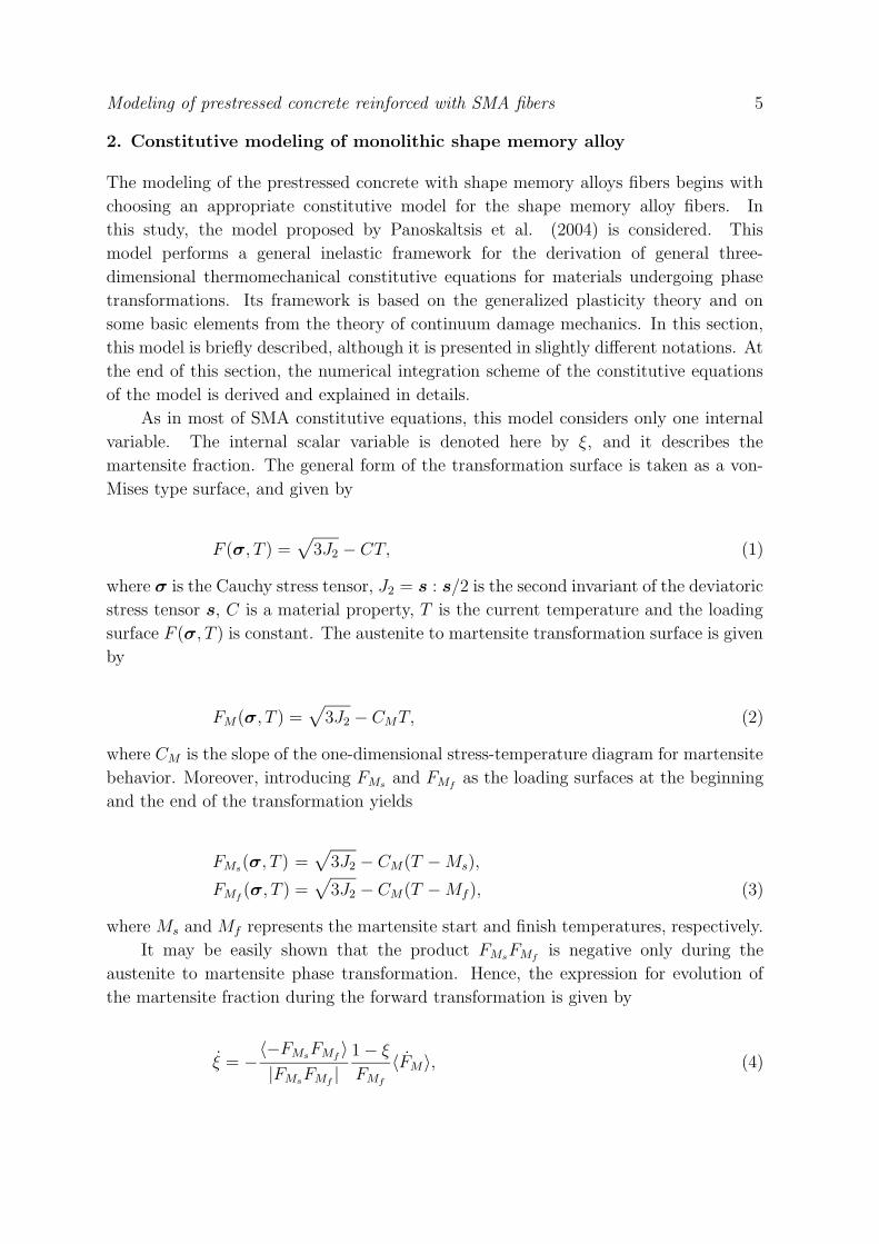
As in most of SMA constitutive equations, this model considers only one internal
variable. The internal scalar variable is denoted here by ξ, and it describes the
martensite fraction. The general form of the transformation surface is taken as a von-
Mises type surface, and given by
F (σ, T ) =√
3J2 − CT, (1)
where σ is the Cauchy stress tensor, J2 = s : s/2 is the second invariant of the deviatoric
stress tensor s, C is a material property, T is the current temperature and the loading
surface F (σ, T ) is constant. The austenite to martensite transformation surface is given
by
FM(σ, T ) =√
3J2 − CMT, (2)
where CM is the slope of the one-dimensional stress-temperature diagram for martensite
behavior. Moreover, introducing FMsand FMf
as the loading surfaces at the beginning
and the end of the transformation yields
FMs(σ, T ) =
√
3J2 − CM(T − Ms),
FMf(σ, T ) =
√
3J2 − CM(T − Mf ), (3)
where Ms and Mf represents the martensite start and finish temperatures, respectively.
It may be easily shown that the product FMsFMf
is negative only during the
austenite to martensite phase transformation. Hence, the expression for evolution of
the martensite fraction during the forward transformation is given by
ξ = −〈−FMs
FMf〉
|FMsFMf
|
1 − ξ
FMf
〈FM〉, (4)
Modeling of prestressed concrete reinforced with SMA fibers 6
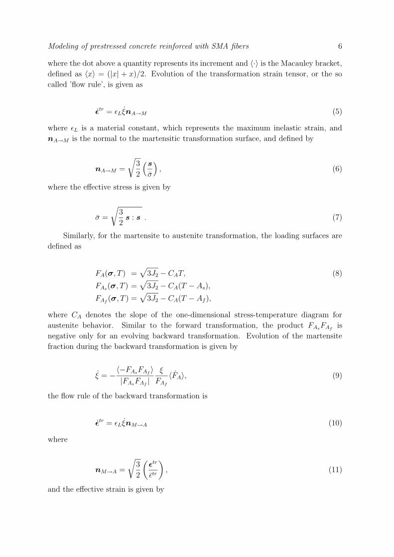
where the dot above a quantity represents its increment and 〈·〉 is the Macauley bracket,
defined as 〈x〉 = (|x| + x)/2. Evolution of the transformation strain tensor, or the so
called ’flow rule’, is given as
εtr = εLξnA→M (5)
where εL is a material constant, which represents the maximum inelastic strain, and
nA→M is the normal to the martensitic transformation surface, and defined by
nA→M =
√
3
2
(
s
σ
)
, (6)
where the effective stress is given by
σ =
√
3
2s : s . (7)
Similarly, for the martensite to austenite transformation, the loading surfaces are
defined as
FA(σ, T ) =√
3J2 − CAT, (8)
FAs(σ, T ) =
√
3J2 − CA(T − As),
FAf(σ, T ) =
√
3J2 − CA(T − Af ),
where CA denotes the slope of the one-dimensional stress-temperature diagram for
austenite behavior. Similar to the forward transformation, the product FAsFAf
is
negative only for an evolving backward transformation. Evolution of the martensite
fraction during the backward transformation is given by
ξ = −〈−FAs
FAf〉
|FAsFAf
|
ξ
FAf
〈FA〉, (9)
the flow rule of the backward transformation is
εtr = εLξnM→A (10)
where
nM→A =
√
3
2
(
εtr
εtr
)
, (11)
and the effective strain is given by
Modeling of prestressed concrete reinforced with SMA fibers 7
εtr =
√
3
2εtr : εtr . (12)
Finally, The constitutive law of the SMA material is given by
σ = C(ξ) : (ε − εtr), (13)
where C is the standard isotropic stiffness matrix but its components depend upon the
internal variable ξ in the form
E = EA + ξm (EM − EA) (14)
and
ν = νA + ξm (νM − νA) , (15)
where EA, EM , νA and νM are the Young’s moduli and Poisson ratios of austenite and
martensite phases, respectively, and m is a positive material parameter, which controls
the slope of the stress-strain curve.
The stress-strain behavior of the material may be separated into several different
branches. It is clear that if FA < 0, backward transformation occurs, while forward
transformation occurs if FM > 0. Since only one internal variable is considered, FA =
FM ; hence, only one phase transformation is active at any given time. Consequently,
the forward and backward transformation may be decoupled into two separate criteria
simply by defining
hM =〈−FMs
FMf〉
|FMsFMf
|, hA =
〈−FAsFAf
〉
|FAsFAf
|. (16)
For a forward transformation,
if, hM = 0 then elastic state
if hM = 1, then
FM < 0 elastic unloading
FM = 0 neutral loading
FM > 0 inelastic loading.
(17)
For a backward transformation,
if hA = 0, then elastic state
if hA = 1, then
FA > 0 elastic unloading
FA = 0 neutral loading
FA < 0 inelastic loading.
(18)
Modeling of prestressed concrete reinforced with SMA fibers 8
From a computational point of view, the non-linear behavior of the model may be
treated as an implicit time discrete strain driven problem. Accordingly, the time discrete
equations of the model are integrated over a time interval (t, t + ∆t) using an implicit
backward Euler scheme, which is unconditionally stable. In the following, the details of
the computational procedure for the determination of the SMA response are presented.
During elastic deformation
ξt+∆t = ξt,
εtr,t+∆t = ε
tr,t, (19)
and the new stress state is determined using eq. (13). For both cases of inelastic loading,
the discrete equations may be derived as
ξt+∆t = ξt + ∆ξ
∆ξ =Rt+∆t
ξ
f t+∆tf
∆F,
∆F =3
2
J t+∆t2 − J t
2
σt+∆t− c(T t+∆t − T t),
J t+∆t2 =
1
2s
t+∆t : st+∆t,
st+∆t =
Et+∆t
1 + νt+∆t
(
εt+∆t −
1
3ε
t+∆t : I − εtr,t+∆t
)
,
εtr,t+∆t = ε
tr,t + ∆ξεLnt+∆t, (20)
where I is the identity matrix, n is given in eqs. (11) and (6) for backward and forward
transformations, respectively,
Rξ = 1 − ξ, ff = −FMf, c = CM , (21)
for the case of a forward transformation, and
Rξ = ξ, ff = FAf, c = CA, (22)
for a backward transformation. The increment of the martensite fraction ∆ξ is obtained
by solving the nonlinear equation
∆ξ −3
2
Rt+∆tξ
f t+∆tf
J t+∆t2 − J t
2
σt+∆t− c(T t+∆t − T t) = 0 , (23)
and the new stress state may be determined using eqs. (20) and (13).
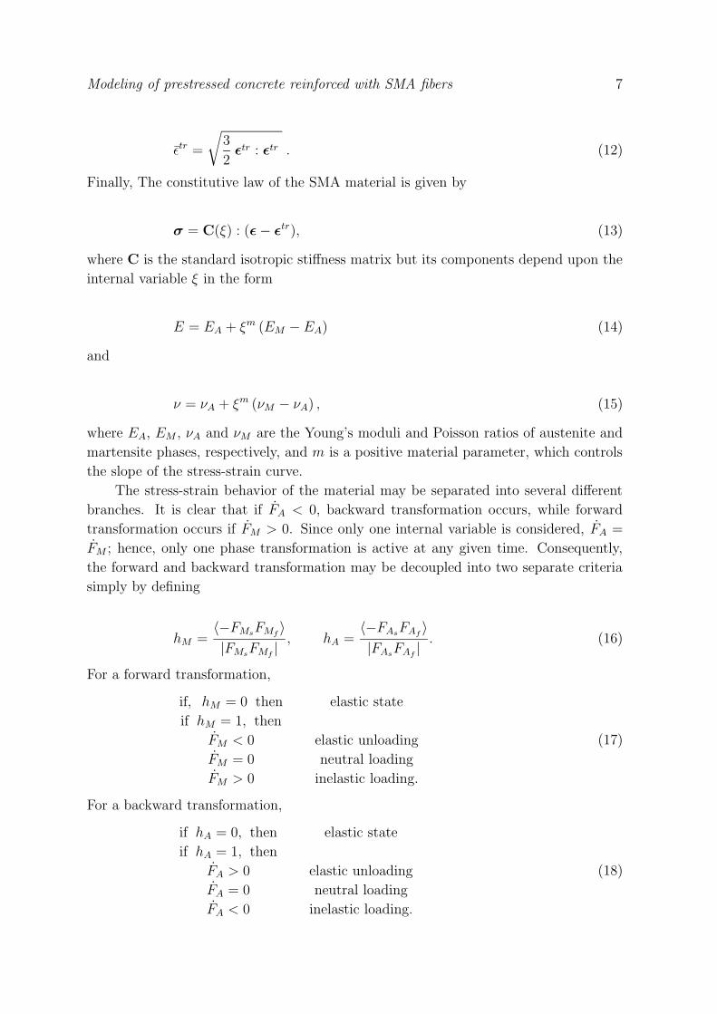
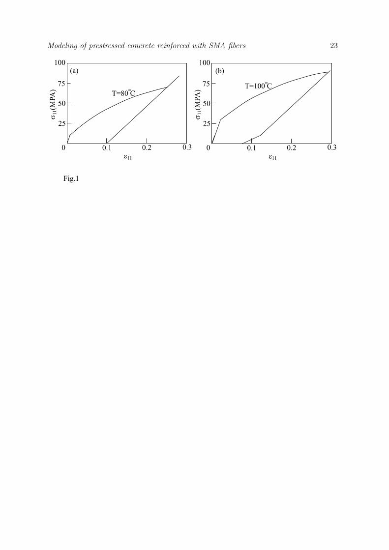
The response of the material during an isothermal strain-driven uniaxial loading-
unloading test is shown in Figs. 1a and 1b for the cases when Ms < T < As and
Modeling of prestressed concrete reinforced with SMA fibers 9
As < T < Af , respectively. In the analyses, Young’s moduli are taken as EM = 500
MPa and EA = 1500 MPa, the Poisson’s ratios νA = νM = 0.3, the transformation
temperatures are Ms = 70◦C, Mf = 10◦C, As = 90◦C, Af = 130◦C, the slopes
CM = CA = 1 MPa/◦C, εL = 0.1 and m = 1. These results agree exactly with those of
Panoskaltsis et al. (2004).
3. Constitutive modeling of plain concrete
In this study, the constitutive model of plain concrete suggested by Tao and Phillips
(2005), was chosen and implemented. This model presents a three-dimensional analysis
of concrete, with a feature of simplicity and avoidance of convergence problems, often
observed in strain softening plasticity. This model describes the strain softening of
a plain concrete in a framework of a continuum damage mechanics, with a weighted
damage parameter and a damage multiplier that eliminates potential convergence
problems and reduce the effect of hydrostatic pressure on damage. It may be noted
that only a brief derivation of the model is given here. For further details, the reader is
directed to Tao and Phillips (2005).
Under isothermal conditions, the Helmholtz free energy may be written as
A =1
2ε : K : ε, (24)
where K is the fourth-order stiffness tensor of the material, and ε is the strain tensor.
Since experimental observations suggest that the failure of concrete is different for
hydrostatic and deviatoric loadings, the above potential may be decoupled as
A =1
2(1 − D) ε : K0 : ε +
(1 − β) D
2ε2mI : K0 : I, (25)
where the stiffness degradation induced by material damage K = (1 − D)K0 is
considered, εm = ε : I/3 is the mean strain, and β denotes for a damage multiplier
that reduces the influence of the hydrostatic loading as
β = 1 −1
1 + cY e−dY(26)
with c and d as material constants and Y as a thermodynamic force. Finally, D is a
combined tension/compression damage parameter
D =
∑
σ+p Dt +
∑
|σ−
p |Dc∑
|σp|, (27)
where σ+p and σ−
p are the positive and negative parts of the principal stress tensor,
respectively,∑
|σp| is the sum of the absolute values of the principal stresses, and Dt
and Dc are scalars that denotes for the damage in tension and compression, respectively.
Modeling of prestressed concrete reinforced with SMA fibers 10
It should be noted that according to eq. (27), the damage in tension does not induce a
damage in compression.
The thermodynamic force Y may be separated to Yt for tension and Yc for
compression as
Yt =∂A
∂Dt
=
∑
σ+p
2∑
|σp|
(
ε : K0 : ε − (1 − β)ε2mI : K0 : I
)
, (28)
Yc =∂A
∂Dc
=
∑
σ−
p
2∑
|σp|
(
ε : K0 : ε − (1 − β)ε2mI : K0 : I
)
, (29)
and
σ =∂A
∂ε= (1 − D)K0 : ε +
(1 − β)Dεm
3(I : K0 : I)I (30)
Since no plastic strain is taken into account in this model, the material tangent and
secant moduli may be determined as
Kt = (1 − D)K0 +(1 − β)D
9(I : K0 : I)I (31)
Finally, limits functions for tension and compression are given by
ft(Yt, Dt) = Yt − Zt = 0 (32)
fc(Yc, Dc) = Yc − Zc = 0 (33)
where the softening parameters Zt and Zc are expressed as
Zt = Y 0t +
1
at
(
Dt
1 − Dt
)1
bt
(34)
Zc = Y 0c +
1
ac
(
Dc
1 − Dc
)1
bc
, (35)
in which parameters at and bt are determined from a simple uniaxial tensile test, while
ac and bc are determined from a uniaxial compression test. The initial values of damage
energy release rates, Y 0t and Y 0
c , are material constants, which denotes for the onset of
the damage in tension and compression, respectively.
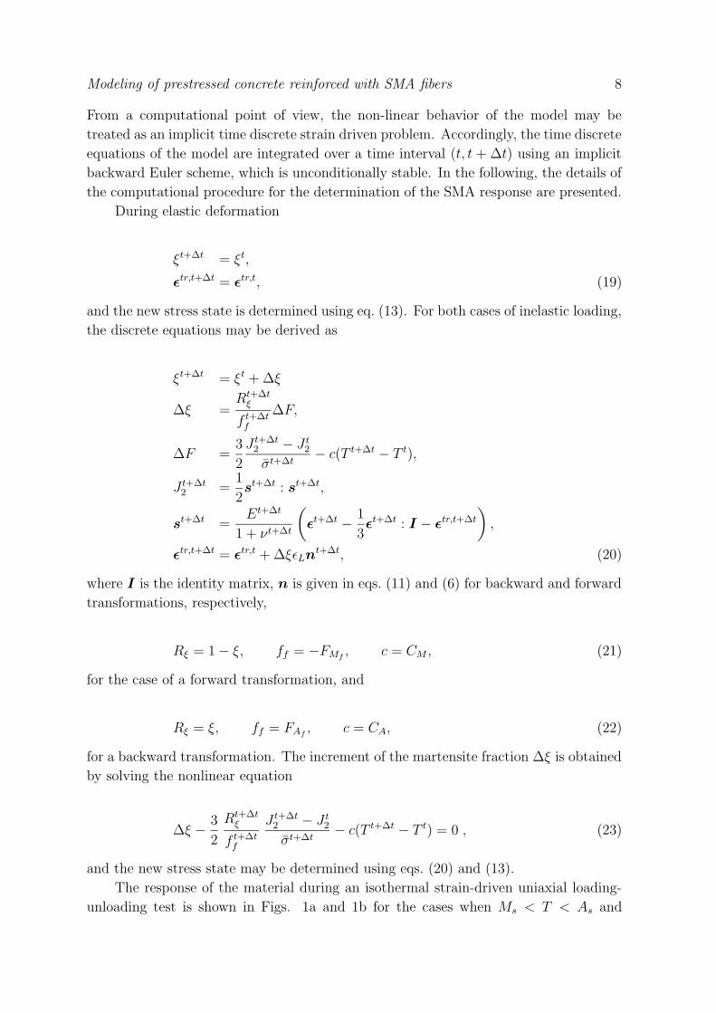
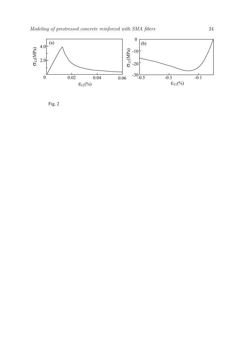
The response of concrete in tension and compression is illustrated in Figs. 2a and
2b, respectively. In the analyses, Young’s modulus was taken as E = 31.8 GPa, with
ν = 0.18, at = 7000 MPa−1, bt = 1.1, ac = 29 MPa−1, bc = 0.94, Y 0t = 1.9 × 10⁻⁴ MPa,
Y 0c = 3 × 10⁻⁴ MPa, c = 2 MPa−1 and d = 0.7 MPa−1. The results are in excellent
agreement with those of Tao and Phillips (2005).
Modeling of prestressed concrete reinforced with SMA fibers 11
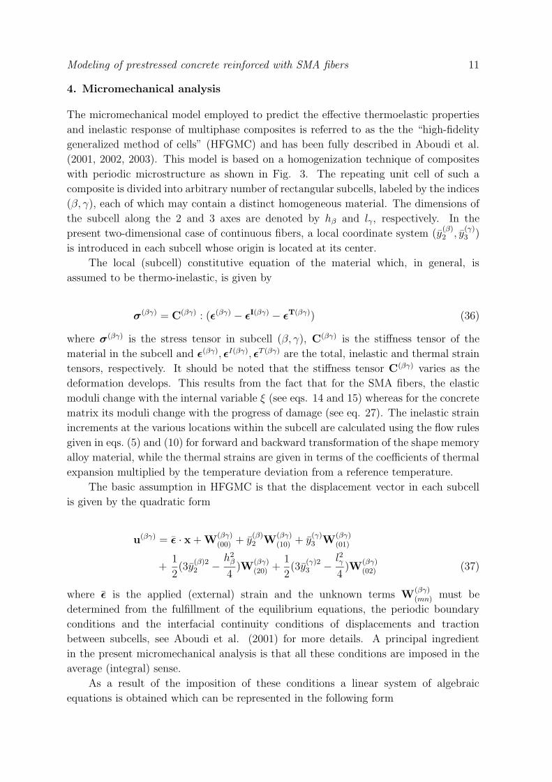
4. Micromechanical analysis
The micromechanical model employed to predict the effective thermoelastic properties
and inelastic response of multiphase composites is referred to as the the “high-fidelity
generalized method of cells” (HFGMC) and has been fully described in Aboudi et al.
(2001, 2002, 2003). This model is based on a homogenization technique of composites
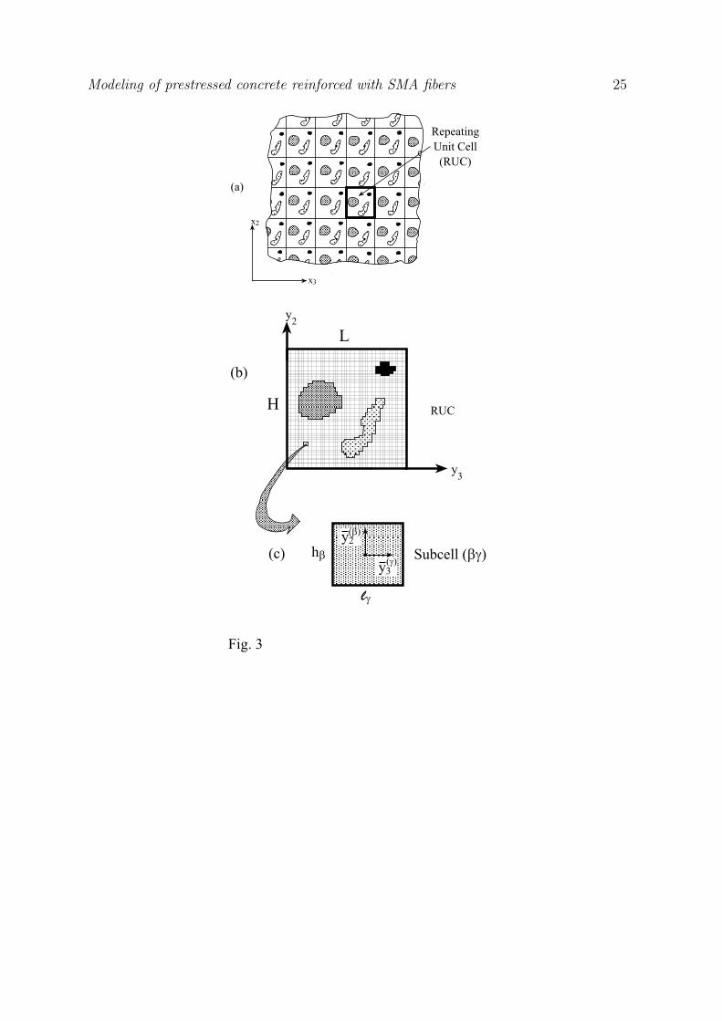
with periodic microstructure as shown in Fig. 3. The repeating unit cell of such a
composite is divided into arbitrary number of rectangular subcells, labeled by the indices
(β, γ), each of which may contain a distinct homogeneous material. The dimensions of
the subcell along the 2 and 3 axes are denoted by hβ and lγ , respectively. In the
present two-dimensional case of continuous fibers, a local coordinate system (y(β)2 , y
(γ)3 )
is introduced in each subcell whose origin is located at its center.
The local (subcell) constitutive equation of the material which, in general, is
assumed to be thermo-inelastic, is given by
σ(βγ) = C(βγ) : (ε(βγ) − ε
I(βγ) − εT(βγ)) (36)
where σ(βγ) is the stress tensor in subcell (β, γ), C(βγ) is the stiffness tensor of the
material in the subcell and ε(βγ), εI(βγ), εT (βγ) are the total, inelastic and thermal strain
tensors, respectively. It should be noted that the stiffness tensor C(βγ) varies as the
deformation develops. This results from the fact that for the SMA fibers, the elastic
moduli change with the internal variable ξ (see eqs. 14 and 15) whereas for the concrete
matrix its moduli change with the progress of damage (see eq. 27). The inelastic strain
increments at the various locations within the subcell are calculated using the flow rules
given in eqs. (5) and (10) for forward and backward transformation of the shape memory
alloy material, while the thermal strains are given in terms of the coefficients of thermal
expansion multiplied by the temperature deviation from a reference temperature.
The basic assumption in HFGMC is that the displacement vector in each subcell
is given by the quadratic form
u(βγ) = ε · x + W(βγ)(00) + y
(β)2 W
(βγ)(10) + y
(γ)3 W
(βγ)(01)
+1
2(3y
(β)22 −
h2β
4)W
(βγ)(20) +
1
2(3y
(γ)23 −
l2γ4
)W(βγ)(02) (37)
where ε is the applied (external) strain and the unknown terms W(βγ)(mn) must be
determined from the fulfillment of the equilibrium equations, the periodic boundary
conditions and the interfacial continuity conditions of displacements and traction
between subcells, see Aboudi et al. (2001) for more details. A principal ingredient
in the present micromechanical analysis is that all these conditions are imposed in the
average (integral) sense.
As a result of the imposition of these conditions a linear system of algebraic
equations is obtained which can be represented in the following form
Modeling of prestressed concrete reinforced with SMA fibers 12
KU = f + g (38)
where the matrix K contains information on the current material properties of the
subcell and its dimensions, U contains the unknown terms W(βγ)(mn) in the displacement
expansion, eq. (37), the f vector contains information on the externally applied strain
and thermal effects, and g contains the inelastic effects expressed by integrals of inelastic
strains.
Once eq. (38) is solved, the local stress and strain fields throughout the repeating
unit cell can be determined. This is accomplished by the establishment of the strain
concentration tensor A(βγ) of the subcell which relates the local field to the externally
applied one (see Aboudi, 2004, for details). As a result, the micromechanically
established constitutive equations that govern the overall (global) behavior of the
multiphase material can be represented in the form
σ = C∗ : (ε − εI + ε
T ) (39)
In this equation, σ is the average stress in the composite, C∗ is its current effective
elastic stiffness tensor, and ε, εI and εT are the overall total, inelastic and thermal
strain tensors, respectively. The latter is given by the effective coefficients of thermal
expansion multiplied by the temperature increment. A notable feature of the present
model is that it provides closed-form expressions for C∗, εI and ε
T (namely for the
effective coefficients of thermal expansion) in terms of the geometry of the repeating
unit cell and the current material properties of its constituents. These closed-form
expressions have been summarized and presented in Aboudi (2004).
It should be noted that the present model is semi analytical and differs in several
aspects from the finite element procedure, as discussed in Aboudi et al. (2002, 2003)
and Aboudi (2004). In particular, the present micromechanical analysis can be used to
analyze a composite structure. It should be noted that a finite element analysis may be
a relatively complicated procedure to obtain the macroscopic inelastic behavior of the
reinforced concrete, since several sets of numerical analyses are needed. However, using a
finite element method for the establishment of the macroscopic constitutive equations of
the SMA/concrete, and employing them subsequently as a consistent tangent modulus
in another structural analysis (possibly in conjunction with a finite element one) appears
to be a formidable task.
5. Problem formulation and results
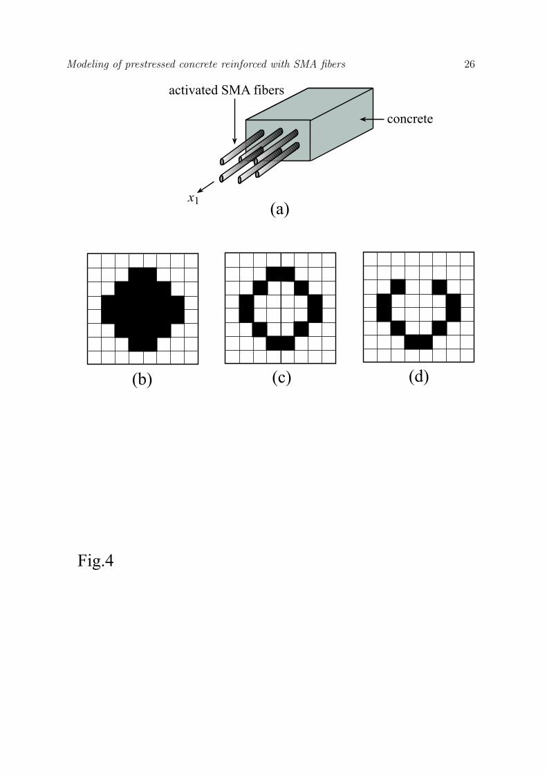
Consider a unidirectional composite that consists of a concrete matrix reinforced by
uniformly distributed SMA fibers which are oriented in the x1 axial direction, see Fig.
4a. The present analyses were carried out for the case of a uniaxial stress loading
in which the composite is subjected to an external strain in the axial direction while
Modeling of prestressed concrete reinforced with SMA fibers 13
keeping all other stress components equal to zero. To this end, the thermomechanically
micromechanical model was examined in several aspects. First, the effect of the shape
of the fibers was examined both for a case of a mismatch between the coefficients of
thermal expansion of the SMA fibers and the concrete matrix, and for a case of zero
thermal expansions. Next, the effects of the activation (as explained in the following)
and the fibers volume fraction were examined. Finally, the transverse response due to
axial loading was examined in terms of activation and volume fraction. Furthermore,
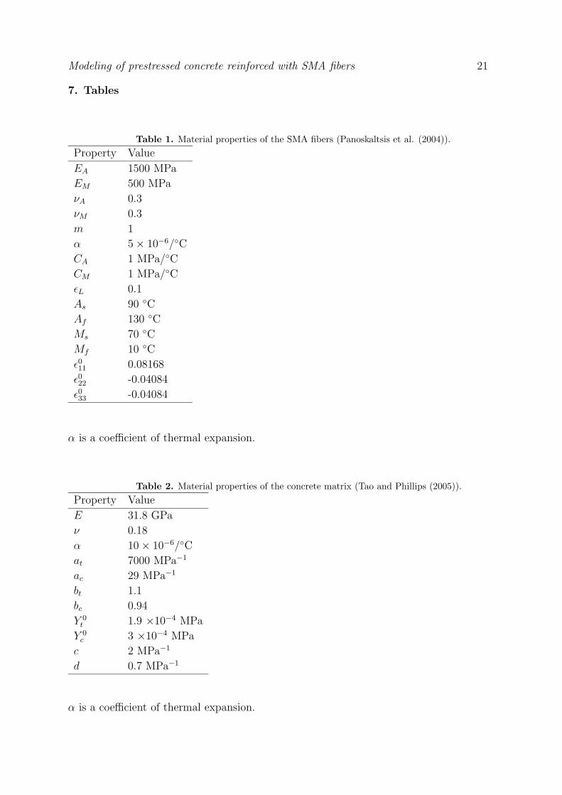
the preferred orientation of the SMA fibers is examined as well. The material properties
of the concrete and the SMA fibers are given in Tables 1 and 2, respectively. These
properties are taken from Tao and Phillips (2005) for concrete, and Panoskaltsis et al.
(2004) for SMA.
In order to model the prestressed concrete, the shape memory effect was utilized.
With this phenomenon, when the initial temperature of the SMA is lower than the
austenite start temperature As, residual strains are generated after loading-unloading
cycle. These strains may be recovered simply by heating to a temperature above the
austenite final temperature Af . Consequently, the activation process was modeled
as follow. First, the SMA fibers were subjected to a loading-unloading cycle with a
temperature below As. As a result, residual strains ε0 (given in Table 1) were generated.
These fibers are embedded in the concrete matrix. Upon subsequent heating of the
composite, these strains were recovered, and compressive stresses were transmitted to
the concrete matrix. By employing the HFGMC, the algorithm for the prestessing
process is as follow:
(i) Fill all subcells with SMA.
(ii) Load and unload the SMA material to get the residual strains, ε0, and the
corresponding internal variables.
(iii) Fill the subcells of the repeating unit cell according to the given composite
configuration.
(iv) Assign zeros for the initial strains and internal variables of the matrix subcells.
(v) The initial global strain, ε, is taken to be zero.
(vi) In the subcells that are filled with SMA fiber, the relation ε(βγ) = ε
0 + Aε is used,
where A(βγ) is the strain concentration tensor of the subcell which is provided by
the micromechanical analysis, while ε0 and the initial value of the internal variable
are those of step (ii). It should be noted that for the micromechanical local-global
relations, only the portion ε(βγ) − ε
0 is considered.
5.1. Effect of the shape of the fibers on the behavior of the prestressed concrete
In this subsection, the effect of the shape of the fibers on the behavior of the prestressed
concrete was examined. To this end, 64 subcells in a configuration of 8 × 8 were
considered. Fibers with three different shapes of cross-section were examined: circle,
ring, and U-shaped, as illustrated in Fig. 4b-d. The reader may recall that the volume
Modeling of prestressed concrete reinforced with SMA fibers 14
fraction of the fiber is relatively small (for example, in Moser et al., 2005, the fiber volume
fraction was 1.2 %), and these figures just show the shape of the fiber qualitatively.
The analyses were carried out for two cases. In the first one, no thermal effects
were considered (i.e., the thermal coefficient of expansion is taken as zero for both SMA
and concrete constituents). In the second case, non-zero thermal expansions (as given in
Tables 1 and 2) were considered. With these two cases, the effect of activation process
may be examined in the absence and presence of thermal expansion. In all cases, the
activation temperature deviation was taken as ∆T = 40◦C with fibers volume fraction
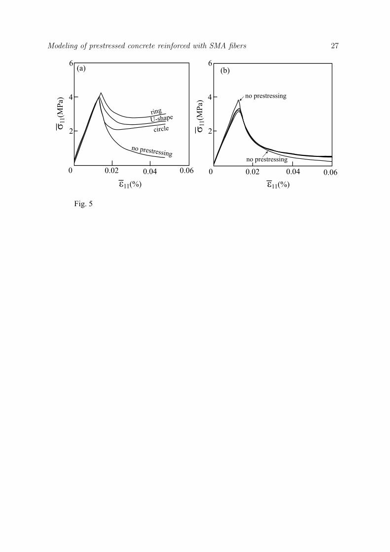
of vf = 1%. The results are illustrated in Fig. 5.
In Fig 5a, stress-strain curves were obtained for different shapes of fibers, with
zero thermal expansions. Hence, the temperature deviation ∆T contributes only to the
activation of the fibers (with all thermal strains equal to zero). From this graph, it
may be observed that all fiber shapes exhibited a better performance as compared to
the plain concrete. In all cases, both the peak of the stress, and the response in the
damaged region exhibited an increase in the stress level. This increase was found to be
approximately 400% to 530% for the different shapes with respect to a concrete with
no prestressing. In particular, it was found that the ring shape, illustrated in Fig.4c, is
the preferred shape of reinforcement. However, it is interesting to observe that once the
temperature deviation ∆T is incorporated with the thermal expansion of the composite’s
phases, the difference between the responses of the fiber shapes is negligible, as shown
in Fig. 5b. Nevertheless, the prestressed composite still exhibits a better performance in
the damaged region, showing an increase of up to 75% in the stress level. To explain this
phenomenon, the reader may recall that the compressive stresses in the concrete result
from the recovery of the residual strains in the SMA fibers. If the thermal expansion
of the composite is considered as well, the thermal strains reduce the effect of the SMA
residual strains on the overall composite, since the volume fraction of the SMA fibers is
relatively small. It may be shown that for relatively high values of vf , the prestressed
concrete exhibits an increase in the stress level.
5.2. Effect of activation and volume fraction on the behavior of prestressed concrete
As mentioned in the previous subsection, the induced temperature has a significant effect
on the behavior of the prestressed concrete. In this subsection, this effect is examined
for a range of activation temperature deviations. From Table 1, it is observed that a
temperature deviation of ∆T = 40◦C is sufficient for a full recovery of a monolithic
SMA (since Af − As = 40◦C). However, since the fibers are embedded in the concrete
matrix, there are obviously internal forces between the two phases which change the
transformation temperatures. Consequently, ∆T = 40◦C is not the optimal temperature
deviation in the sense that full recovery is not necessarily achieved.
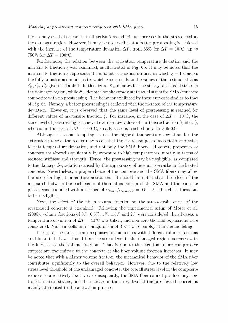
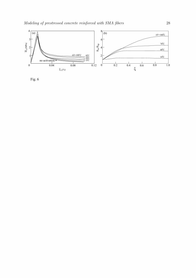
In Fig. 6a, the behavior of the prestressed concrete at different activation
temperature deviations is shown. In all cases, 9 subcells in a configuration of 3 × 3,
with fibers volume fraction of 1%, and non-zero thermal expansions were considered. In
Modeling of prestressed concrete reinforced with SMA fibers 15
these analyses, It is clear that all activations exhibit an increase in the stress level at
the damaged region. However, it may be observed that a better prestressing is achieved
with the increase of the temperature deviation ∆T , from 33% for ∆T = 10◦C, up to
750% for ∆T = 100◦C.
Furthermore, the relation between the activation temperature deviation and the
martensite fraction ξ was examined, as illustrated in Fig. 6b. It may be noted that the
martensite fraction ξ represents the amount of residual strains, in which ξ = 1 denotes
the fully transformed martensite, which corresponds to the values of the residual strains
ε011, ε
022, ε
033 given in Table 1. In this figure, σss denotes for the steady state axial stress in
the damaged region, while σnp denotes for the steady state axial stress for SMA/concrete
composite with no prestressing. The behavior exhibited by these curves is similar to that
of Fig. 6a. Namely, a better prestressing is achieved with the increase of the temperature
deviation. However, it is observed that the same level of prestressing is reached for
different values of martensite fraction ξ. For instance, in the case of ∆T = 10◦C, the
same level of prestressing is achieved even for low values of martensite fraction (ξ ∼= 0.1),
whereas in the case of ∆T = 100◦C, steady state is reached only for ξ ∼= 0.9.
Although it seems tempting to use the highest temperature deviation for the
activation process, the reader may recall that the entire composite material is subjected
to this temperature deviation, and not only the SMA fibers. However, properties of
concrete are altered significantly by exposure to high temperatures, mostly in terms of
reduced stiffness and strength. Hence, the prestressing may be negligible, as compared
to the damage degradation caused by the appearance of new micro-cracks in the heated
concrete. Nevertheless, a proper choice of the concrete and the SMA fibers may allow
the use of a high temperature activation. It should be noted that the effect of the
mismatch between the coefficients of thermal expansion of the SMA and the concrete
phases was examined within a range of αSMA/αconcrete = 0.5 − 2. This effect turns out
to be negligible.
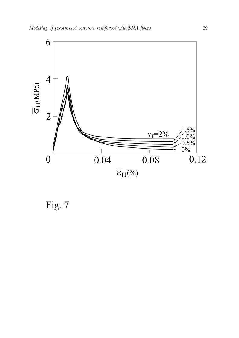
Next, the effect of the fibers volume fraction on the stress-strain curve of the
prestressed concrete is examined. Following the experimental setup of Moser et al.
(2005), volume fractions of 0%, 0.5%, 1%, 1.5% and 2% were considered. In all cases, a
temperature deviation of ∆T = 40◦C was taken, and non-zero thermal expansions were
considered. Nine subcells in a configuration of 3 × 3 were employed in the modeling.
In Fig. 7, the stress-strain responses of composites with different volume fractions
are illustrated. It was found that the stress level in the damaged region increases with
the increase of the volume fraction. That is due to the fact that more compressive
stresses are transmitted to the concrete as the fiber volume fraction increases. It may
be noted that with a higher volume fraction, the mechanical behavior of the SMA fiber
contributes significantly to the overall behavior. However, due to the relatively low
stress level threshold of the undamaged concrete, the overall stress level in the composite
reduces to a relatively low level. Consequently, the SMA fiber cannot produce any new
transformation strains, and the increase in the stress level of the prestressed concrete is
mainly attributed to the activation process.
Modeling of prestressed concrete reinforced with SMA fibers 16
5.3. The transverse response of the prestressed concrete
It is interesting to study the resulting transverse response of the prestressed concrete
due to axial loading. This response was examined by means of activation temperature
deviations, and for a range of fiber volume fractions. In all cases, 9 subcells in a 3 × 3
configuration were considered.
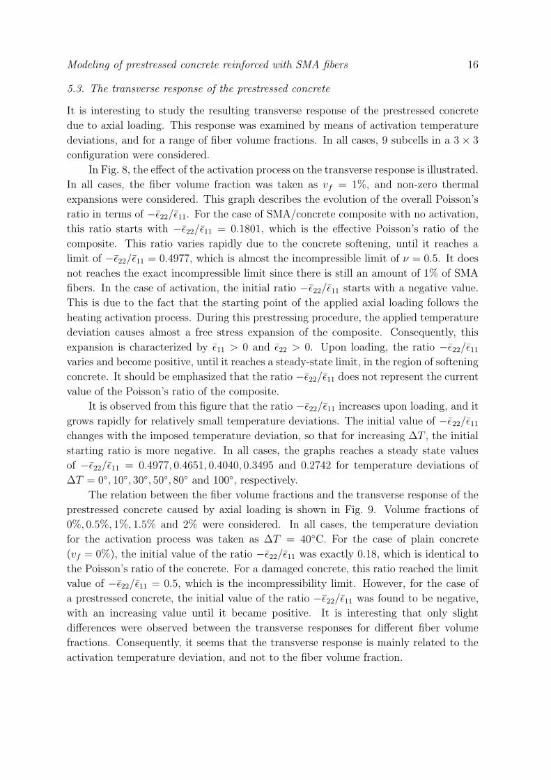
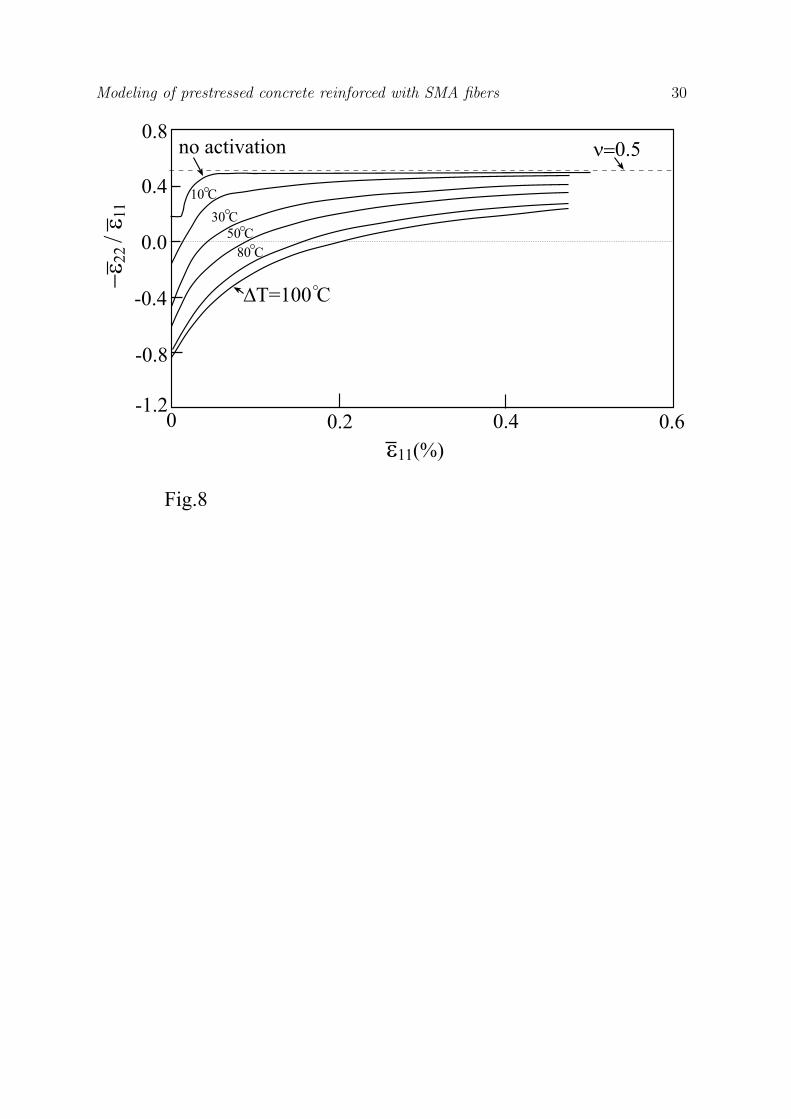
In Fig. 8, the effect of the activation process on the transverse response is illustrated.
In all cases, the fiber volume fraction was taken as vf = 1%, and non-zero thermal
expansions were considered. This graph describes the evolution of the overall Poisson’s
ratio in terms of −ε22/ε11. For the case of SMA/concrete composite with no activation,
this ratio starts with −ε22/ε11 = 0.1801, which is the effective Poisson’s ratio of the
composite. This ratio varies rapidly due to the concrete softening, until it reaches a
limit of −ε22/ε11 = 0.4977, which is almost the incompressible limit of ν = 0.5. It does
not reaches the exact incompressible limit since there is still an amount of 1% of SMA
fibers. In the case of activation, the initial ratio −ε22/ε11 starts with a negative value.
This is due to the fact that the starting point of the applied axial loading follows the
heating activation process. During this prestressing procedure, the applied temperature
deviation causes almost a free stress expansion of the composite. Consequently, this
expansion is characterized by ε11 > 0 and ε22 > 0. Upon loading, the ratio −ε22/ε11
varies and become positive, until it reaches a steady-state limit, in the region of softening
concrete. It should be emphasized that the ratio −ε22/ε11 does not represent the current
value of the Poisson’s ratio of the composite.
It is observed from this figure that the ratio −ε22/ε11 increases upon loading, and it
grows rapidly for relatively small temperature deviations. The initial value of −ε22/ε11
changes with the imposed temperature deviation, so that for increasing ∆T , the initial
starting ratio is more negative. In all cases, the graphs reaches a steady state values
of −ε22/ε11 = 0.4977, 0.4651, 0.4040, 0.3495 and 0.2742 for temperature deviations of
∆T = 0◦, 10◦, 30◦, 50◦, 80◦ and 100◦, respectively.
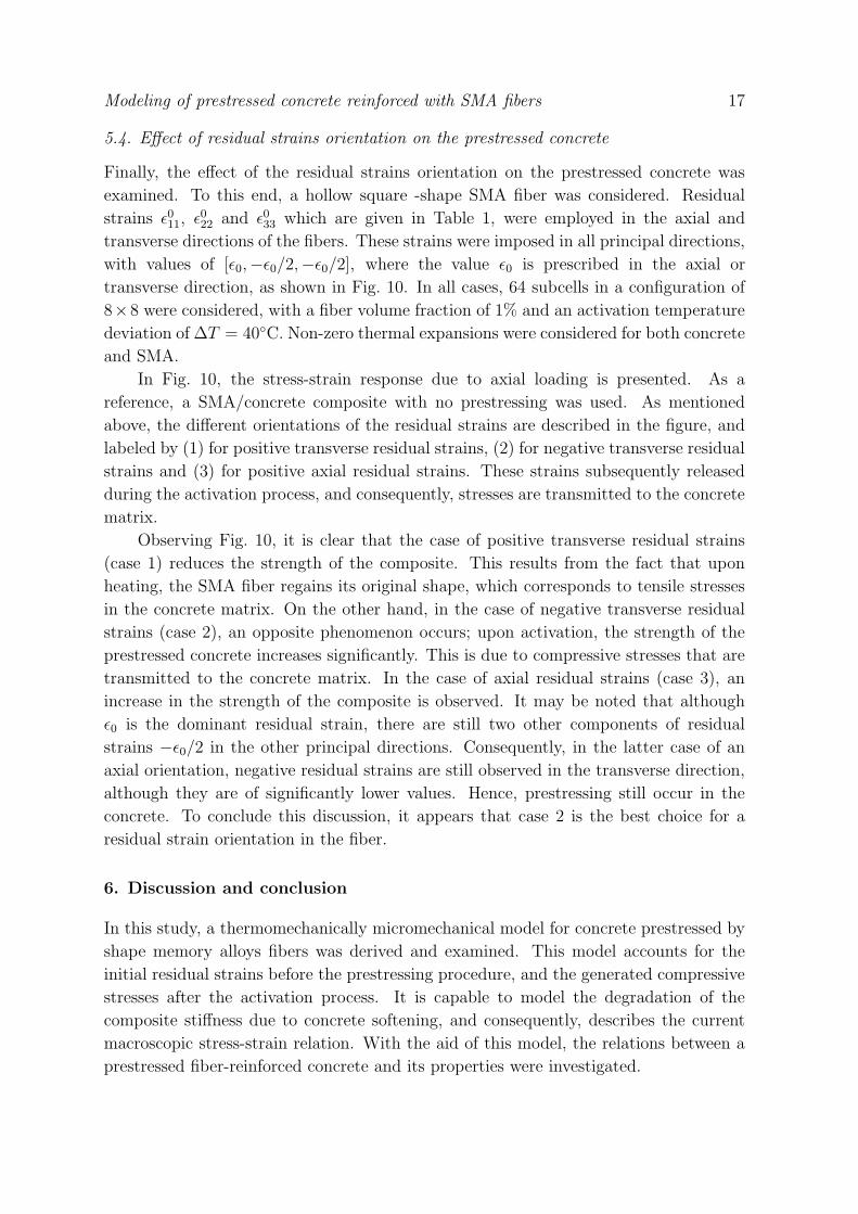
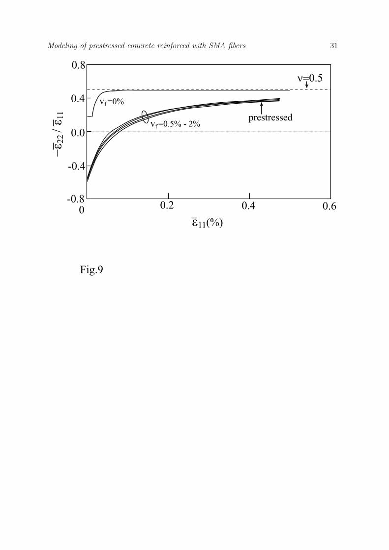
The relation between the fiber volume fractions and the transverse response of the
prestressed concrete caused by axial loading is shown in Fig. 9. Volume fractions of
0%, 0.5%, 1%, 1.5% and 2% were considered. In all cases, the temperature deviation
for the activation process was taken as ∆T = 40◦C. For the case of plain concrete
(vf = 0%), the initial value of the ratio −ε22/ε11 was exactly 0.18, which is identical to
the Poisson’s ratio of the concrete. For a damaged concrete, this ratio reached the limit
value of −ε22/ε11 = 0.5, which is the incompressibility limit. However, for the case of
a prestressed concrete, the initial value of the ratio −ε22/ε11 was found to be negative,
with an increasing value until it became positive. It is interesting that only slight
differences were observed between the transverse responses for different fiber volume
fractions. Consequently, it seems that the transverse response is mainly related to the
activation temperature deviation, and not to the fiber volume fraction.
Modeling of prestressed concrete reinforced with SMA fibers 17
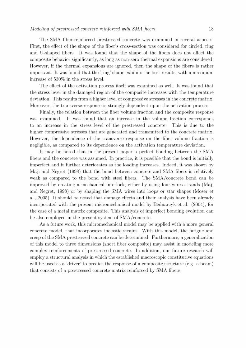
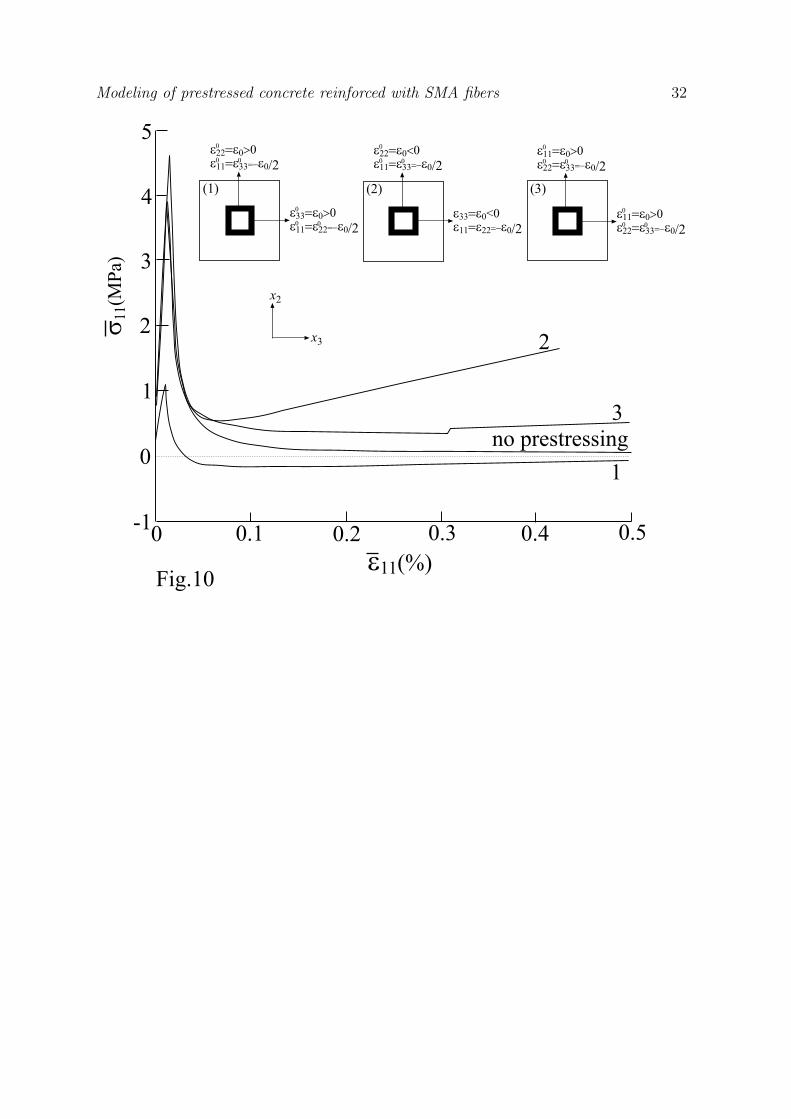
5.4. Effect of residual strains orientation on the prestressed concrete
Finally, the effect of the residual strains orientation on the prestressed concrete was
examined. To this end, a hollow square -shape SMA fiber was considered. Residual
strains ε011, ε0
22 and ε033 which are given in Table 1, were employed in the axial and
transverse directions of the fibers. These strains were imposed in all principal directions,
with values of [ε0,−ε0/2,−ε0/2], where the value ε0 is prescribed in the axial or
transverse direction, as shown in Fig. 10. In all cases, 64 subcells in a configuration of
8×8 were considered, with a fiber volume fraction of 1% and an activation temperature
deviation of ∆T = 40◦C. Non-zero thermal expansions were considered for both concrete
and SMA.
In Fig. 10, the stress-strain response due to axial loading is presented. As a
reference, a SMA/concrete composite with no prestressing was used. As mentioned
above, the different orientations of the residual strains are described in the figure, and
labeled by (1) for positive transverse residual strains, (2) for negative transverse residual
strains and (3) for positive axial residual strains. These strains subsequently released
during the activation process, and consequently, stresses are transmitted to the concrete
matrix.
Observing Fig. 10, it is clear that the case of positive transverse residual strains
(case 1) reduces the strength of the composite. This results from the fact that upon
heating, the SMA fiber regains its original shape, which corresponds to tensile stresses
in the concrete matrix. On the other hand, in the case of negative transverse residual
strains (case 2), an opposite phenomenon occurs; upon activation, the strength of the
prestressed concrete increases significantly. This is due to compressive stresses that are
transmitted to the concrete matrix. In the case of axial residual strains (case 3), an
increase in the strength of the composite is observed. It may be noted that although
ε0 is the dominant residual strain, there are still two other components of residual
strains −ε0/2 in the other principal directions. Consequently, in the latter case of an
axial orientation, negative residual strains are still observed in the transverse direction,
although they are of significantly lower values. Hence, prestressing still occur in the
concrete. To conclude this discussion, it appears that case 2 is the best choice for a
residual strain orientation in the fiber.
6. Discussion and conclusion
In this study, a thermomechanically micromechanical model for concrete prestressed by
shape memory alloys fibers was derived and examined. This model accounts for the
initial residual strains before the prestressing procedure, and the generated compressive
stresses after the activation process. It is capable to model the degradation of the
composite stiffness due to concrete softening, and consequently, describes the current
macroscopic stress-strain relation. With the aid of this model, the relations between a
prestressed fiber-reinforced concrete and its properties were investigated.
Modeling of prestressed concrete reinforced with SMA fibers 18
The SMA fiber-reinforced prestressed concrete was examined in several aspects.
First, the effect of the shape of the fiber’s cross-section was considered for circled, ring
and U-shaped fibers. It was found that the shape of the fibers does not affect the
composite behavior significantly, as long as non-zero thermal expansions are considered.
However, if the thermal expansions are ignored, then the shape of the fibers is rather
important. It was found that the ’ring’ shape exhibits the best results, with a maximum
increase of 530% in the stress level.
The effect of the activation process itself was examined as well. It was found that
the stress level in the damaged region of the composite increases with the temperature
deviation. This results from a higher level of compressive stresses in the concrete matrix.
Moreover, the transverse response is strongly dependent upon the activation process.
Finally, the relation between the fiber volume fraction and the composite response
was examined. It was found that an increase in the volume fraction corresponds
to an increase in the stress level of the prestressed concrete. This is due to the
higher compressive stresses that are generated and transmitted to the concrete matrix.
However, the dependence of the transverse response on the fiber volume fraction is
negligible, as compared to its dependence on the activation temperature deviation.
It may be noted that in the present paper a perfect bonding between the SMA
fibers and the concrete was assumed. In practice, it is possible that the bond is initially
imperfect and it further deteriorates as the loading increases. Indeed, it was shown by
Maji and Negret (1998) that the bond between concrete and SMA fibers is relatively
weak as compared to the bond with steel fibers. The SMA/concrete bond can be
improved by creating a mechanical interlock, either by using four-wires strands (Maji
and Negret, 1998) or by shaping the SMA wires into loops or star shapes (Moser et
al., 2005). It should be noted that damage effects and their analysis have been already
incorporated with the present micromechanical model by Bednarcyk et al. (2004), for
the case of a metal matrix composite. This analysis of imperfect bonding evolution can
be also employed in the present system of SMA/concrete.
As a future work, this micromechanical model may be applied with a more general
concrete model, that incorporates inelastic strains. With this model, the fatigue and
creep of the SMA prestressed concrete can be determined. Furthermore, a generalization
of this model to three dimensions (short fiber composite) may assist in modeling more
complex reinforcements of prestressed concrete. In addition, our future research will
employ a structural analysis in which the established macroscopic constitutive equations
will be used as a ’driver’ to predict the response of a composite structure (e.g. a beam)
that consists of a prestressed concrete matrix reinforced by SMA fibers.
Modeling of prestressed concrete reinforced with SMA fibers 19
References
Aboudi J., Pindera M-J. and Arnold S.M., Linear thermoelastic higher-order theory for periodic
multiphase materials. Journal of Applied Mechanics, 68: 697-707 (2001).
Aboudi J., Pindera M.-J. and Arnold S.M., High-fidelity generalized method of cells for inelastic periodic
multiphase materials. NASA TM-2002-211469 (2002).
Aboudi J., Pindera M.-J. and Arnold S.M., Higher-order theory for periodic multiphase materials with
inelastic phases. International Journal of Plasticity, 19: 805-847 (2003).
Aboudi J., The generalized method of cells and high-fidelity generalized method of cells micromechanical
models - a review. Mechanics of Advanced Materials and Structures, 11: 329-366 (2004).
Aboudi J. and Freed Y., Two-way thermomechanically coupled micromechanical analysis of shape
memory alloy composites. Journal of Mechanics of Materials and Structures, 1: 937-955 (2006).
Bednarcyk B.A., Arnold S.M. Aboudi, J. and Pindera M-J., Local field effects in titanium matrix
composites subject to fiber-matrix debonding. International Journal of Plasticity, 20: 1707-1737
(2004).
Boyd J.G. and Lagoudas D.C., Thermomechanical response of shape memory composites. Journal of
Intelligent Materials, Systems and Structures, 5: 333-346 (1994).
Carvelli V. and Taliercio A., Micromechanical model for the analysis of unidirectional elasto-plastic
composites subjected to 3D stresses. Mechanics Research Communications, 26: 547-553 (1999).
Deng Z.C., Li Q.B., Jiu A. and Li L., Behavior of concrete driven by uniaxially embedded shape memory
alloy actuators. Journal of Engineering Mechanics, 129: 697-703 (2003).
Deng Z.C., Li Q.B. and Sun H.J., Behavior of concrete beam with embedded shape memory alloy wires.
Engineering Structures, 28: 1691-1697 (2006).
El-Tawil S. and Ortega-Rosales J., Prestressing concrete using shape memory alloy tendons. ACI
Structural Journal , 101: 846-851 (2004).
Gilat R. and Aboudi J., Dynamic response of active composite plates: shape memory alloy fibers in
polymeric/metallic matrices. International Journal of Solids and Structures, 41: 5717-5731 (2004).
Gilat R. and Aboudi J., Thermal buckling of activated shape memory reinforced laminated plates.
Smart Materials and Structures, 15: 829-838 (2006).
Janke L., Czaderski C., Motavalli M. and Ruth J., Applications of shape memory alloys in civil
engineering structures - Overview, limits and new ideas. Materials and Structures, 38:578-592
(2005).
Kawai M., Ogawa H., Baburaj V. and Koga T., Micromechanical analysis for hysteretic behavior
of unidirectional TiNi SMA Fiber Composite. Journal of Intelligent Materials, Systems and
Structures, 10: 14-28 (1996).
Kawai M., Effects of matrix inelasticity on the overall hysteretic behavior of TiNi-SMA fiber composites.
International Journal of Plasticity, 16: 263-282 (2000).
Maji A.K. and Negret I., Smart prestressing with shape-memory alloy. Journal of Engineering
Mechanics, 124: 1121-1128 (1998).
Marfia S., Micro-macro analysis of shape memory alloy composites. International Journal of Solids and
Structures, 42: 3677-3699 (2005).
Moser K., Bergamini A., Christen R. and Czaderski C., Feasibility of concrete prestressed by shape
memory alloy short fibers. Materials and Structures, 38: 593-600 (2005).
Panoskaltsis V.P., Bahuguna S. and Soldatos D., On the thermomechanical modeling of shape memory
alloys. International Journal of Non-Linear Mechanics, 39: 709-722 (2004).
Sawaguchi T., Kikuchi T., Ogawa K., Kajiwara S., Ikeo Y., Kojima M. and Ogawa T., Development
of prestressed concrete using Fe-Mn-Si-based shape memory alloys containing NbC. Materials
Transactions, 47: 580-583 (2006).
Song, G.Q., Sun, Q.P. and Cherkaoui, M., Role of microstructures in the thermomechanical behavior
of SMA composites. Journal of Engineering Materials and Technology, 121: 86-92 (1999).
Tao X.Y. and Phillips D.V., A simplified isotropic damage model for concrete under bi-axial stress

Modeling of prestressed concrete reinforced with SMA fibers 20
states. Cement and Concrete Composites , 27: 716-726 (2005).
Modeling of prestressed concrete reinforced with SMA fibers 21
7. Tables
Table 1. Material properties of the SMA fibers (Panoskaltsis et al. (2004)).
Property Value
EA 1500 MPa
EM 500 MPa
νA 0.3
νM 0.3
m 1
α 5 × 10⁻⁶/◦C
CA 1 MPa/◦C
CM 1 MPa/◦C
εL 0.1
As 90 ◦C
Af 130 ◦C
Ms 70 ◦C
Mf 10 ◦C
ε011 0.08168
ε022 -0.04084
ε033 -0.04084
α is a coefficient of thermal expansion.
Table 2. Material properties of the concrete matrix (Tao and Phillips (2005)).
Property Value
E 31.8 GPa
ν 0.18
α 10 × 10−6/◦C
at 7000 MPa−1
ac 29 MPa−1
bt 1.1
bc 0.94
Y 0t 1.9 ×10⁻⁴ MPa
Y 0c 3 ×10⁻⁴ MPa
c 2 MPa−1
d 0.7 MPa−1
α is a coefficient of thermal expansion.
Modeling of prestressed concrete reinforced with SMA fibers 22
Figure Captions
Fig. 1: One dimensional loading-unloading behavior for (a) Ms < T < As and (b) As <
T < Af .
Fig. 2: One dimensional behavior for (a) uniaxial tension and (b) uniaxial compression.
Fig. 3: (a) A multiphase composite with doubly-periodic microstructures defined with
respect to global coordinates (x2, x3). (b) The repeating unit cell is represented
with respect to local coordinates (y2, y3). It is divided into Nβ and Nγ subcells, in
the y2 and y3 directions, respectively. (c) A characteristic subcell (βγ) with local
coordinates y(β)2 and y
(γ)3 whose origin is located at its center.
Fig. 4: (a) Activated SMA fibers (oriented in the x1-direction) embedded in a concrete
matrix. The shapes of fibers are: (b) circle, (c) ring and (d) U-shaped.
Fig. 5: Effect of the shape of the SMA fibers on the behavior of the prestressed concrete:
(a) Thermal expansion is not considered. (b) Thermal expansion is considered.
Fig. 6: (a) Effect of activation on the behavior of the prestressed concrete. (b) The ratio of
the steady state axial stress σss and the steady state axial stress in a SMA/concrete
composite with no prestressing σnp versus the martensite fraction ξ for different
values of temperature deviations.
Fig. 7: Effect of fibers volume fraction vf on the behavior of the prestressed concrete.
Fig. 8: Effect of activation temperature deviations on the transverse response of a
prestressed concrete.
Fig. 9: Effect of fibers volume fraction vf on the transverse response of a prestressed
concrete.
Fig. 10: Effect of residual strains orientation on the response of a prestressed concrete. A
square-shape SMA fiber is considered for three different orientations.
Modeling of prestressed concrete reinforced with SMA fibers 23
100
75
50
25
0
(a)
0.2 0.3
T=80 C
e11
s 11(
MPA
)
0.1
100
75
50
25
0
(b)
0.2 0.3e11
s 11(
MPA
)
0.1
T=100 C
Fig.1
Modeling of prestressed concrete reinforced with SMA fibers 24
4.0
2.0
0 0.02 0.04 0.06 -0.5 -0.3 -0.1
-10
-20
-30
0(b)(a)
Fig. 2
e11(%) e11(%)
s 11(
MPa
)
s 11(
MPa
)
Modeling of prestressed concrete reinforced with SMA fibers 25
Fig. 3
(c) hb
lg
y3(g)
y2(b)
Subcell (bg)
(b)
x3
x2
RepeatingUnit Cell(RUC)
(a)
H
L
y3
y2
RUC
Modeling of prestressed concrete reinforced with SMA fibers 26
(b) (c) (d)
Fig.4
concrete
activated SMA fibers
x1(a)
Modeling of prestressed concrete reinforced with SMA fibers 27
0.02 0.04 0.060
2
4
6(a)
no prestressingno prestressing
0.02 0.04 0.060
(b)
2
4
6
Fig. 5
e11(%) e11(%)
s 11(
MPa
)
s 11(
MPa
)
ringU-shape
circle
no prestressing
Modeling of prestressed concrete reinforced with SMA fibers 28
Fig. 6
0.120.04 0.080
2
4
no activation
3
1
e11(%)
s 11(
MPa
)
80 C50 C30 C10 C
(a)
DT=100 C
8
6
4
2
0 0.2 0.4 0.6 0.8 1.0x
70 C
40 C
10 C
DT=100 C(b)
s ss/
s np
Modeling of prestressed concrete reinforced with SMA fibers 29
0.120.04 0.080
2
4
Fig. 7
6
e11(%)
s 11(
MPa
)
vf =2%1.5%1.0%0.5%0%
Modeling of prestressed concrete reinforced with SMA fibers 30
0.8no activation
0.4
0.0
-0.4
-0.8
-1.20 0.2 0.4 0.6
Fig.8
e11(%)
-e22
/ e 1
1
DT=100 C
n=0.5
80 C50 C
30 C
10 C
Modeling of prestressed concrete reinforced with SMA fibers 31
0 0.2 0.4 0.6
Fig.9
-0.8
-0.4
0.4
0.0
0.8
prestressed
e11(%)
-e22
/ e 1
1
n=0.5
vf =0.5% - 2%
vf =0%
Modeling of prestressed concrete reinforced with SMA fibers 32
0.50.40.30.20.10
0
-1
1
2
3
4
5
2
3no prestressing
1
Fig.10e11(%)
(1) (3)
s 11(
MPa
)
e33=e0>0e11=e22=-e0/2
0
0 0
e22=e0>0e11=e33=-e0/2
0
0 0
(2)
e33=e0<0e11=e22=-e0/2
e22=e0<0e11=e33=-e0/2
0
0 0
e11=e0>0e22=e33=-e0/2
0
0 0
e11=e0>0e22=e33=-e0/2
0
0 0
x2
x3