A NEW LOOK AT THE DETECTION OF INTERRUPTED … · a new look at the detection of interrupted and...
7
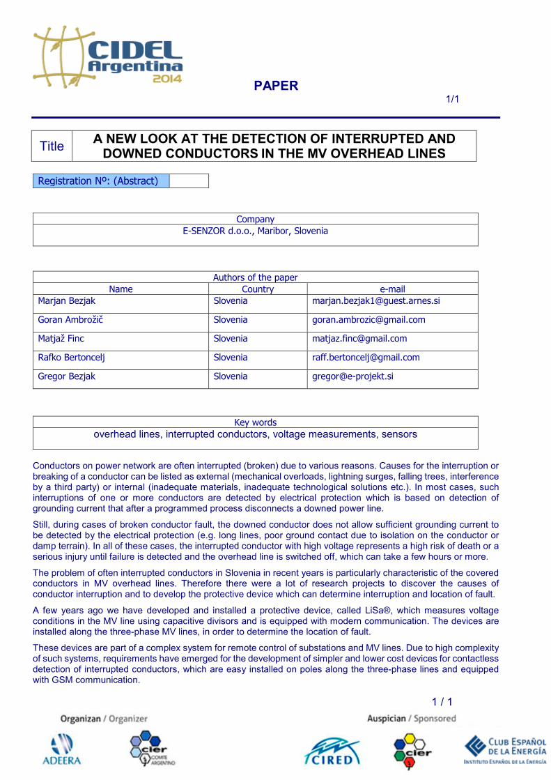
PAPER 1/1 1 / 1 Title A NEW LOOK AT THE DETECTION OF INTERRUPTED AND DOWNED CONDUCTORS IN THE MV OVERHEAD LINES Registration Nº: (Abstract) Company E-SENZOR d.o.o., Maribor, Slovenia Authors of the paper Name Country e-mail Marjan Bezjak Slovenia [email protected] Goran Ambrožič Slovenia [email protected] Matjaž Finc Slovenia [email protected] Rafko Bertoncelj Slovenia [email protected] Gregor Bezjak Slovenia [email protected] Key words overhead lines, interrupted conductors, voltage measurements, sensors Conductors on power network are often interrupted (broken) due to various reasons. Causes for the interruption or breaking of a conductor can be listed as external (mechanical overloads, lightning surges, falling trees, interference by a third party) or internal (inadequate materials, inadequate technological solutions etc.). In most cases, such interruptions of one or more conductors are detected by electrical protection which is based on detection of grounding current that after a programmed process disconnects a downed power line. Still, during cases of broken conductor fault, the downed conductor does not allow sufficient grounding current to be detected by the electrical protection (e.g. long lines, poor ground contact due to isolation on the conductor or damp terrain). In all of these cases, the interrupted conductor with high voltage represents a high risk of death or a serious injury until failure is detected and the overhead line is switched off, which can take a few hours or more. The problem of often interrupted conductors in Slovenia in recent years is particularly characteristic of the covered conductors in MV overhead lines. Therefore there were a lot of research projects to discover the causes of conductor interruption and to develop the protective device which can determine interruption and location of fault. A few years ago we have developed and installed a protective device, called LiSa®, which measures voltage conditions in the MV line using capacitive divisors and is equipped with modern communication. The devices are installed along the three-phase MV lines, in order to determine the location of fault. These devices are part of a complex system for remote control of substations and MV lines. Due to high complexity of such systems, requirements have emerged for the development of simpler and lower cost devices for contactless detection of interrupted conductors, which are easy installed on poles along the three-phase lines and equipped with GSM communication.
-
Upload
nguyenkhanh -
Category
Documents
-
view
232 -
download
0
Transcript of A NEW LOOK AT THE DETECTION OF INTERRUPTED … · a new look at the detection of interrupted and...
PAPER 1/1
1 / 1
Title A NEW LOOK AT THE DETECTION OF INTERRUPTED AND
DOWNED CONDUCTORS IN THE MV OVERHEAD LINES
Registration Nº: (Abstract)
Company E-SENZOR d.o.o., Maribor, Slovenia
Authors of the paper Name Country e-mail
Marjan Bezjak Slovenia [email protected]
Goran Ambrožič Slovenia [email protected]
Matjaž Finc Slovenia [email protected]
Rafko Bertoncelj Slovenia [email protected]
Gregor Bezjak Slovenia [email protected]
Key words
overhead lines, interrupted conductors, voltage measurements, sensors
Conductors on power network are often interrupted (broken) due to various reasons. Causes for the interruption or breaking of a conductor can be listed as external (mechanical overloads, lightning surges, falling trees, interference by a third party) or internal (inadequate materials, inadequate technological solutions etc.). In most cases, such interruptions of one or more conductors are detected by electrical protection which is based on detection of grounding current that after a programmed process disconnects a downed power line.
Still, during cases of broken conductor fault, the downed conductor does not allow sufficient grounding current to be detected by the electrical protection (e.g. long lines, poor ground contact due to isolation on the conductor or damp terrain). In all of these cases, the interrupted conductor with high voltage represents a high risk of death or a serious injury until failure is detected and the overhead line is switched off, which can take a few hours or more.
The problem of often interrupted conductors in Slovenia in recent years is particularly characteristic of the covered conductors in MV overhead lines. Therefore there were a lot of research projects to discover the causes of conductor interruption and to develop the protective device which can determine interruption and location of fault.
A few years ago we have developed and installed a protective device, called LiSa®, which measures voltage conditions in the MV line using capacitive divisors and is equipped with modern communication. The devices are installed along the three-phase MV lines, in order to determine the location of fault.
These devices are part of a complex system for remote control of substations and MV lines. Due to high complexity of such systems, requirements have emerged for the development of simpler and lower cost devices for contactless detection of interrupted conductors, which are easy installed on poles along the three-phase lines and equipped with GSM communication.

1
A NEW LOOK AT THE DETECTION OF INTERRUPTED AND DOWNED
CONDUCTORS IN THE MV OVERHEAD LINES
Marjan Bezjak, Goran Ambrožič, Matjaž Finc, Rafko Bertoncelj, Gregor Bezjak
[email protected], [email protected], [email protected],
[email protected], [email protected]
ABSTRACT
This paper presents a method for contactless
detection of downed conductor faults in overhead
lines. The results of theoretical analysis, simulations
of multi-phase electrical fields, measurements on an
MV test field and also on real MV lines are
presented, compared and interpreted. A model is
introduced based on a variation of electrical
parameters. This model is based on measuring
different parameters of the electric field and can be
applied to networks with different conductor
geometries (horizontal, triangular…). The
developed prototype sensor devices, which can be
implemented along a three-phase radial line and
integrated into a protection system (SCADA) via
GSM communication, are described.
Keywords: overhead lines, interrupted
conductors, voltage measurements, sensors
1 INTRODUCTION
Interrupted and downed conductors are
hazardous when energized. Therefore, they have to
be quickly detected and repaired. When a downed
line creates a high-impedance fault (HIF) e.g.
conductor falls onto soil, asphalt, foliage, dry snow,
rocks or, in the case of covered conductors or long
lines, the fault current is so low that conventional
protection devices are often unable to detect it.
The nature of HIF has been widely studied
since the early 1960s with the aim of finding a
practical method for detecting such disturbances.
Various detection techniques have been studied [1,
2, 3]. In general, two approaches are the most
common, based on sensing changes in:
• current with its harmonic and non-harmonic
frequency components; protection is at the
beginning of the line, together with feeder
protection [4, 5, 6, 7, 8],
• voltage: protection devices are installed along
the line for determining the locations of failures
and at the end of the line [2, 9, 10, 11, 12, 13,
14, 15].
Current protection of HIF operates in the
same way and in the same position as conventional
protection, but determining the location of the failure
is difficult and false alarms cannot be ruled out.
Monitoring voltage changes along the radial
lines serves as a relatively simple and reliable
detection of energized open conductors. Voltage
detectors can be easily connected to the Medium
Voltage (MV) lines via voltage transformers or
capacitive dividers on the pole [13] or can be
integrated into a power quality monitoring system at
MV/LV transformer stations [12, 14, 15]. Beside
using wired communication infrastructure [9, 10],
modern low-power autonomous wireless technology
enables easier distribution of voltage detectors and
independent integration into the SCADA systems.
Contactless voltage monitoring sensors with
wireless communication would make fault detection
systems radically easier to install and cheaper to
maintain as long as they provide robust and reliable
fault detection. We introduce an approach based on
contactless voltage monitoring using electrical field
sensors.
2 THEORY
2.1 Single Probe System
Three conductors 1, 2 and 3 (spacing d, height
H) with identical properties and geometry are placed
above earth. A small conductive probe 4 is placed at
distance h below the middle line. The configuration
is illustrated in Figure 1.
Figure 1 – Single probe configuration
Due to symmetry, the line configuration can
be represented by the substitute capacitive circuit as
illustrated in Figure 2.
Figure 2 – Capacitive circuit

2
By applying a symmetrical three-phase
source to the conductors, we can derive the
following model from the introduced circuit:
�� � ��� ∙ sin�� sin�� � ∙ sin��� �1�
� �����
2�� �� ��
�2�
� ���
��
�3�
The model shows that, measuring the
amplitude can be much more volatile (in relation to
generator voltage amplitude and geometry i.e.
substitute capacitances), while the phase angle is
only defined by a simple constant ratio η,
independent of generator voltage and can be
interpreted more easily. Different situations can be
displayed on a phasor diagram as in Figure 3.
Figure 3 – Single probe diagram
When all phase voltages are present
(reference condition), the result is a phasor:
�� � ���1 � �� ∙ sin��� �4�
By changing the location of the probe (h),
ratio η varies and therefore the ratio of amplitudes
during different scenarios (i.e. reference condition
and faults) can be interpreted from the diagram.
2.2 Dual Probe System
If we upgrade the model to dual probes,
spaced for x from the central line through the middle
conductor as in Figure 4, we can approximate the
new model by using different ratios for potentials V4
and V5:
�� � ���� ∙ sin�� sin�� �� ∙ sin��� �5�
�� � ���� ∙ sin�� sin�� �� ∙ sin��� �6�
Figure 4 – Dual probe configuration
If we display the model on the phasor
diagram, as in Figure 5, we can see that in the
reference condition, the phase angle difference
between V4 and V5 is wider than during faults. For
open conductors, single phase presence or fault
modulation through the end-of-line symmetrical
load (e.g. transformer), the difference in phase angle
is similarly different from the reference condition.
Figure 5 – Dual probe diagram
For other symmetrical line configurations
(e.g. delta), the model still applies, but with different
K and ratio η, meaning the probes must be positioned
at different locations for similar phase angle
behavior.
3 MEASUREMENTS
3.1 Sensors
We have experimented with different
configurations of sensor architecture and probe
shapes for contactless measurements. We can divide
the sensor types into two groups:
• single probe type (Figure 6),
• dual probe type (Figure 7).
Both types are autonomous battery powered
electronic devices, housed within a protective case.
Each external voltage sensing probe is connected to
a dedicated amplifier, which measures the potential
between the probe and the printed circuit board
(PCB) reference plane. Data is processed within an
internal processing unit and stored using internal
storage. The data can be collected remotely (e.g. sent
3
via GSM) and/or downloaded by local wired
connection.
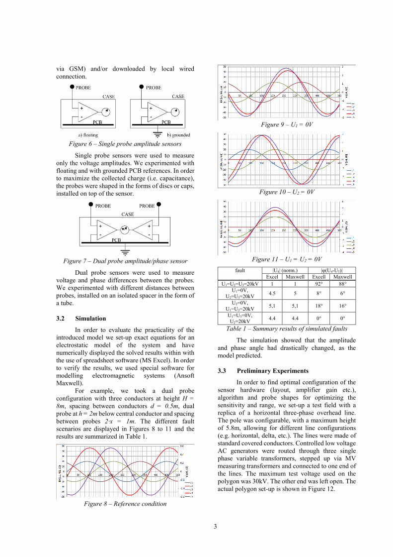
Figure 6 – Single probe amplitude sensors
Single probe sensors were used to measure
only the voltage amplitudes. We experimented with
floating and with grounded PCB references. In order
to maximize the collected charge (i.e. capacitance),
the probes were shaped in the forms of discs or caps,
installed on top of the sensor.
Figure 7 – Dual probe amplitude/phase sensor
Dual probe sensors were used to measure
voltage and phase differences between the probes.
We experimented with different distances between
probes, installed on an isolated spacer in the form of
a tube.
3.2 Simulation
In order to evaluate the practicality of the
introduced model we set-up exact equations for an
electrostatic model of the system and have
numerically displayed the solved results within with
the use of spreadsheet software (MS Excel). In order
to verify the results, we used special software for
modelling electromagnetic systems (Ansoft
Maxwell).
For example, we took a dual probe
configuration with three conductors at height H =
8m, spacing between conductors d = 0.5m, dual
probe at h = 2m below central conductor and spacing
between probes 2·x = 1m. The different fault
scenarios are displayed in Figures 8 to 11 and the
results are summarized in Table 1.
Figure 8 – Reference condition
Figure 9 – U1 = 0V
Figure 10 – U2 = 0V
Figure 11 – U1 = U2 = 0V
fault |U4| (norm.) |φ(U4-U5)|
Excel Maxwell Excell Maxwell
U1=U2=U3=20kV 1 1 92° 88°
U1=0V, U2=U3=20kV
4.5 5 8° 6°
U2=0V,
U1=U3=20kV 5,1 5,1 18° 16°
U1=U3=0V, U2=20kV
4.4 4.4 0° 0°
Table 1 – Summary results of simulated faults
The simulation showed that the amplitude
and phase angle had drastically changed, as the
model predicted.
3.3 Preliminary Experiments
In order to find optimal configuration of the
sensor hardware (layout, amplifier gain etc.),
algorithm and probe shapes for optimizing the
sensitivity and range, we set-up a test field with a
replica of a horizontal three-phase overhead line.
The pole was configurable, with a maximum height
of 5.8m, allowing for different line configurations
(e.g. horizontal, delta, etc.). The lines were made of
standard covered conductors. Controlled low voltage
AC generators were routed through three single
phase variable transformers, stepped up via MV
measuring transformers and connected to one end of
the lines. The maximum test voltage used on the
polygon was 30kV. The other end was left open. The
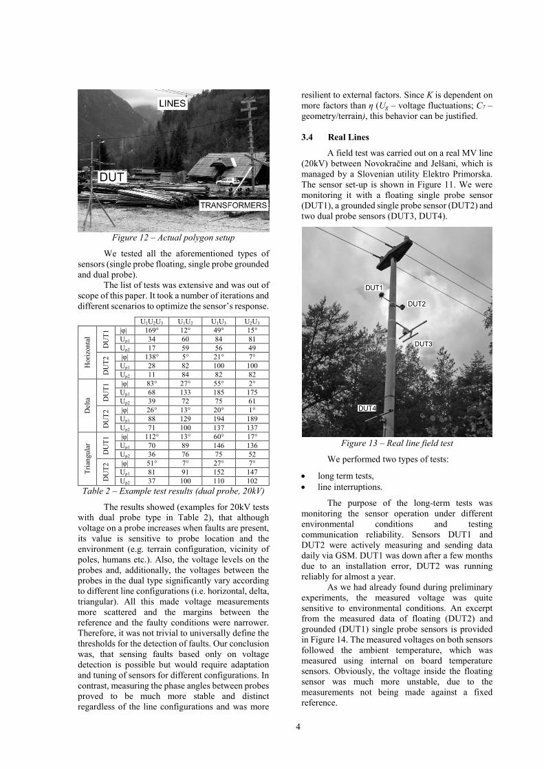
actual polygon set-up is shown in Figure 12.
4
Figure 12 – Actual polygon setup
We tested all the aforementioned types of
sensors (single probe floating, single probe grounded
and dual probe).
The list of tests was extensive and was out of
scope of this paper. It took a number of iterations and
different scenarios to optimize the sensor’s response.
U1U2U3 U1U2 U1U3 U2U3
Ho
rizo
nta
l
DU
T1 |φ| 169° 12° 49° 15°
Up1 34 60 84 81
Up2 17 59 56 49
DU
T2 |φ| 138° 5° 21° 7°
Up1 28 82 100 100
Up2 11 84 82 82
Del
ta
DU
T1 |φ| 83° 27° 55° 2°
Up1 68 133 185 175
Up2 39 72 75 61
DU
T2 |φ| 26° 13° 20° 1°
Up1 88 129 194 189
Up2 71 100 137 137
Tri
angu
lar
DU
T1 |φ| 112° 13° 60° 17°
Up1 70 89 146 136
Up2 36 76 75 52
DU
T2 |φ| 51° 7° 27° 7°
Up1 81 91 152 147
Up2 37 100 110 102
Table 2 – Example test results (dual probe, 20kV)
The results showed (examples for 20kV tests
with dual probe type in Table 2), that although
voltage on a probe increases when faults are present,
its value is sensitive to probe location and the
environment (e.g. terrain configuration, vicinity of
poles, humans etc.). Also, the voltage levels on the
probes and, additionally, the voltages between the
probes in the dual type significantly vary according
to different line configurations (i.e. horizontal, delta,
triangular). All this made voltage measurements
more scattered and the margins between the
reference and the faulty conditions were narrower.
Therefore, it was not trivial to universally define the
thresholds for the detection of faults. Our conclusion
was, that sensing faults based only on voltage
detection is possible but would require adaptation
and tuning of sensors for different configurations. In
contrast, measuring the phase angles between probes
proved to be much more stable and distinct
regardless of the line configurations and was more
resilient to external factors. Since K is dependent on
more factors than η (Ug – voltage fluctuations; C7 –
geometry/terrain), this behavior can be justified.
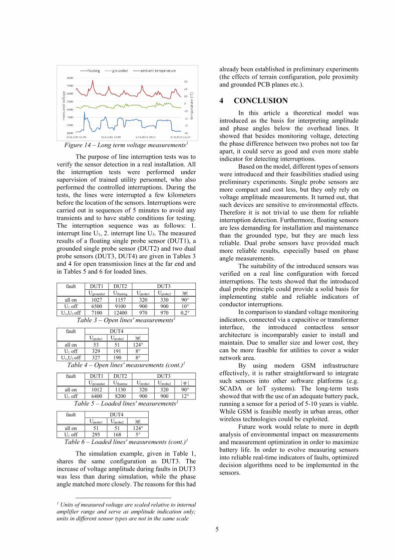
3.4 Real Lines
A field test was carried out on a real MV line
(20kV) between Novokračine and Jelšani, which is
managed by a Slovenian utility Elektro Primorska.
The sensor set-up is shown in Figure 11. We were
monitoring it with a floating single probe sensor
(DUT1), a grounded single probe sensor (DUT2) and
two dual probe sensors (DUT3, DUT4).
Figure 13 – Real line field test
We performed two types of tests:
• long term tests,
• line interruptions.
The purpose of the long-term tests was
monitoring the sensor operation under different
environmental conditions and testing
communication reliability. Sensors DUT1 and
DUT2 were actively measuring and sending data
daily via GSM. DUT1 was down after a few months
due to an installation error, DUT2 was running
reliably for almost a year.
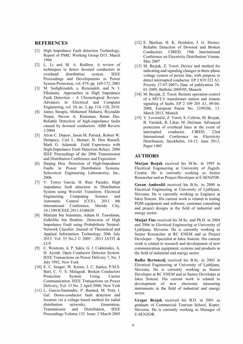
As we had already found during preliminary
experiments, the measured voltage was quite
sensitive to environmental conditions. An excerpt
from the measured data of floating (DUT2) and
grounded (DUT1) single probe sensors is provided
in Figure 14. The measured voltages on both sensors
followed the ambient temperature, which was
measured using internal on board temperature
sensors. Obviously, the voltage inside the floating
sensor was much more unstable, due to the
measurements not being made against a fixed
reference.
5
Figure 14 – Long term voltage measurements1
The purpose of line interruption tests was to
verify the sensor detection in a real installation. All
the interruption tests were performed under
supervision of trained utility personnel, who also
performed the controlled interruptions. During the
tests, the lines were interrupted a few kilometers
before the location of the sensors. Interruptions were
carried out in sequences of 5 minutes to avoid any
transients and to have stable conditions for testing.
The interruption sequence was as follows: 1.
interrupt line U1, 2. interrupt line U3. The measured
results of a floating single probe sensor (DUT1), a
grounded single probe sensor (DUT2) and two dual
probe sensors (DUT3, DUT4) are given in Tables 3
and 4 for open transmission lines at the far end and
in Tables 5 and 6 for loaded lines.
fault DUT1 DUT2 DUT3
Ugrounded Ufloating Uprobe1 Uprobe2 |φ|
all on 1027 1157 320 330 90°
U1 off 6500 9100 900 900 10°
U1,U3 off 7100 12400 970 970 0,2°
Table 3 – Open lines' measurements1
fault DUT4
Uprobe1 Uprobe2 |φ|
all on 53 51 124°
U1 off 329 191 8°
U1,U3 off 327 190 8°
Table 4 – Open lines' measurements (cont.)1
fault DUT1 DUT2 DUT3
Ugrounded Ufloating Uprobe1 Uprobe2 | φ |
all on 1012 1130 320 320 90°
U1 off 6400 8200 900 900 12°
Table 5 – Loaded lines' measurements1
fault DUT4
Uprobe1 Uprobe2 |φ|
all on 51 51 124°
U1 off 295 168 5°
Table 6 – Loaded lines' measurements (cont.)1
The simulation example, given in Table 1,
shares the same configuration as DUT3. The
increase of voltage amplitude during faults in DUT3
was less than during simulation, while the phase
angle matched more closely. The reasons for this had
1 Units of measured voltage are scaled relative to internal
amplifier range and serve as amplitude indication only;
units in different sensor types are not in the same scale
already been established in preliminary experiments
(the effects of terrain configuration, pole proximity
and grounded PCB planes etc.).
4 CONCLUSION
In this article a theoretical model was
introduced as the basis for interpreting amplitude
and phase angles below the overhead lines. It
showed that besides monitoring voltage, detecting
the phase difference between two probes not too far
apart, it could serve as good and even more stable
indicator for detecting interruptions.
Based on the model, different types of sensors
were introduced and their feasibilities studied using
preliminary experiments. Single probe sensors are
more compact and cost less, but they only rely on
voltage amplitude measurements. It turned out, that
such devices are sensitive to environmental effects.
Therefore it is not trivial to use them for reliable
interruption detection. Furthermore, floating sensors
are less demanding for installation and maintenance
than the grounded type, but they are much less
reliable. Dual probe sensors have provided much
more reliable results, especially based on phase
angle measurements.
The suitability of the introduced sensors was
verified on a real line configuration with forced
interruptions. The tests showed that the introduced
dual probe principle could provide a solid basis for
implementing stable and reliable indicators of
conductor interruptions.
In comparison to standard voltage monitoring
indicators, connected via a capacitive or transformer
interface, the introduced contactless sensor
architecture is incomparably easier to install and
maintain. Due to smaller size and lower cost, they
can be more feasible for utilities to cover a wider
network area.
By using modern GSM infrastructure
effectively, it is rather straightforward to integrate
such sensors into other software platforms (e.g.
SCADA or IoT systems). The long-term tests
showed that with the use of an adequate battery pack,
running a sensor for a period of 5-10 years is viable.
While GSM is feasible mostly in urban areas, other
wireless technologies could be exploited.
Future work would relate to more in depth
analysis of environmental impact on measurements
and measurement optimization in order to maximize
battery life. In order to evolve measuring sensors
into reliable real-time indicators of faults, optimized
decision algorithms need to be implemented in the
sensors.
6
REFERENCES
[1] High Impedance Fault detection Technology,
Report of PSRC Working Group D15, March
1996
[2] L. Li and M. A. Redfern. A review of
techniques to detect downed conductors in
overhead distribution system. IEEE
Proceedings and Developments in Power
System Protection, vol. 479, pp. 169-172, 2001
[3] M. Sedighizadeh, a. Rezazadeh, and N. I.
Elkalashy. Approaches in High Impedance
Fault Detection - A Chronological Review.
Advances in Electrical and Computer
Engineering, vol. 10, no. 3, pp. 114–128, 2010.
[4] James Stoupis, Mohamed Maharsi, Reynaldo
Nuqui, Steven A. Kunsman, Ratan Das.
Reliable Detection of high-impedance faults
caused by downed conductors. ABB Review
1/2004
[5] Alvin C. Depew, Jason M. Parsick, Robert W.
Dempsey, Carl L. Benner, B. Don Russell,
Mark G. Adamiak. .Field Experience with
High-Impedance Fault Detection Relays. 2006
IEEE Proceedings of the 2006 Transmission
and Distribution Conference and Exposition
[6] Daqing Hou. Detection of High-Impedance
Faults in Power Distribution Systems.
Schweitzer Engineering Laboratories, Inc.,
2006
[7] V. Torres Garcia, H. Ruiz Paredes. High
impedance fault detection in Distribution
System using Wavelet Transform. Electrical
Engineering Computing Science and
Automatic Control (CCE), 2011 8th
International Conference, Merida City,
10.1109/ICEEE.2011.6106620
[8] Marizan bin Sulaiman, Adnan H. Tawafanm,
Zulkifilie bin Ibrahim. .Detection of High
Impedance Fault using Probabilistic Neutral-
Network Classfier. Journal of Theoretical and
Applied Information Technology 20th July
2013. Vol. 53 No.2 © 2005 - 2013 JATIT &
LLS
[9] C. Westrom, A. P. Sakis, G. J. Cokkinides, A.
H. Ayoub. Open Conductor Detector System.
IEEE Transactions on Power Delivery 7, No. 3
July 1992, New York
[10] E. C. Senger, W. Kaiser, J. C. Santos, P.M.S.
Burt, C. V. S. Malagodi. Broken Conductors
Protection System Using Carrier
Communication. IEEE Transactions on Power
Delivery, Vol. 15 No. 2 April 2000, New York
[11] L. Garcia-Santander, P. Bastard, M. Petit, I.
Gal. Down-conductor fault detection and
location via a voltage based method for radial
distribution networks, Generation,
Transmission and Distribution, IEEE
Proceedings Volume:152 Issue: 2 March 2005
[12] E. Bjerkan, H. K. Hoidalen, J. G. Hernes.
Reliable Detection of Downed and Broken
Conductors. CIRED, 19th International
Conference on Electricity Distribution Vienna,
May 2007
[13] M. Bezjak, Z. Toroš. Device and method for
indicating and signaling changes in three-phase
voltage system of power line, with purpose to
detect interrupted conductor. EP 2 019 323 A1,
Priority 27-07-2007« Date of publication 28-
01-2009, Bulletin 2009/05, Munich
[14] M. Bezjak, Z. Toroš. Remote operation control
of a MV/LV transformer station and remote
signaling of faults. EP 2 109 205 A1, 09-04-
2008, European Patent No. 2109206, 13.
March 2013, Munich
[15] V. Lovrenčič, Z. Toroš, S. Ceferin, M. Bezjak,
B. Turnšek, B. Likar, M. Dečman. Advanced
protection of overhead lines in the event of
interrupted conductor. CIRED, 22nd
International Conference on Electricity
Distribution, Stockholm, 10-13, June 2013,
Paper 1405
AUTHORS
Marjan Bezjak received his M.Sc. in 1995 in
Electrical Engineering at University of Zagreb,
Croatia. He is currently working as Senior
Researcher and as Project Developer at E-SENZOR.
Goran Ambrožič received his B.Sc. in 2000 in
Electrical Engineering at University of Ljubljana,
Slovenia. He is currently working as Engineer at
Iskra Sistemi. His current work is related to testing
PQM equipment and software, customer consulting
and project designs in the field of industrial and
energy sector.
Matjaž Finc received his M.Sc. and Ph.D. in 2004
and 2006 in Electrical Engineering at University of
Ljubljana, Slovenia. He is currently working as
Senior Researcher at RC ENEM and as Project
Developer – Specialist at Iskra Sistemi. His current
work is related to research and development of new
communication equipment, systems and products in
the field of industrial and energy sector.
Rafko Bertoncelj received his B.Sc. in 2002 in
Electrical Engineering at University of Ljubljana,
Slovenia. He is currently working as Senior
Developer at RC ENEM and as Senior Developer at
Iskra Sistemi. His current work is related to
development of new electronic measuring
instruments in the field of industrial and energy
sector.
Gregor Bezjak received his B.D. in 2001 as
graduate of Commercial Tourism School, Koper,
Slovenia. He is currently working as Manager of
E-SENZOR.