a% · Mechani cal Prope.rti es of Graphi te/Polyi~i de and Polyquinoxal ine Composi tes ... materi...
38
tiCD0i;I:ELL DOUGLAS IECllliICP,L SEI'\VICES CO. JlOliSTOI1 bST3GiU',UTICS DIVISION NASA CR- ,,~~770 __uI.. L. SPACE SJtUTTLE EI;GIIIEERII!C AI.iD OPEPS,TICf~SSUPPORT DESIGN I'IOTE 140. 1 .2-131-1-80104-1 ADVA~~CED CGI4POSITES - I:iECHAMI CAL PROPERTIES AF!D HARGGIAEE P ROGRAIlS FOR SELECTED RESIN IdATRIX I4ATERIALS 31 March 1976 This Design Note is Subnii t t e d t o IIASA Under Task Order No. B0404, In Partial Fulfillment of Contract !]AS 9-13970. 2 # / . > I PREPARED GY : - a% %?ddd APPROVED .BY : Eniin K. ~lelktrt Staff Engineer 488-5660, Ext. 274 488-5660, Ext. 274 . APPROVED fi* L. Frazee APPROVED B Y : f & f $ J - . R. Step en Fechni cal Nanager Project b'anager w. . 488-5660, Ext. 234 . 488-5660, Ext. 204 *-- 4 47705) ACYANCED COIPOSiTES : N76-24364 EfiOPER'PIIS ANC HIREWARE PSCGRANS SELECTED RESIN EATRIX MATERIALS (McDonnell-Douglas Technical Services) 38 p Unclas HC $4.OC CSCL 17C G3/24 41455 https://ntrs.nasa.gov/search.jsp?R=19760017276 2019-03-13T18:09:24+00:00Z
Transcript of a% · Mechani cal Prope.rti es of Graphi te/Polyi~i de and Polyquinoxal ine Composi tes ... materi...

tiCD0i;I:ELL DOUGLAS IECllliICP,L SEI'\VICES CO. JlOliSTOI1 bST3GiU',UTICS DIVISION
NASA CR-
, , ~ ~ 7 7 0 5 __uI..
L.
SPACE SJtUTTLE EI;GIIIEERII!C AI.iD OPEPS,TICf~S SUPPORT
DESIGN I'IOTE 140. 1 .2-131-1-80104-1
A D V A ~ ~ C E D CGI4POS ITES - I:iECHAMI CAL PROPERTIES AF!D HARGGIAEE P ROGRAIlS FOR SELECTED RESIN IdATRIX
I4ATERIALS
31 March 1976
This Design Note is Subnii t t e d t o IIASA Under Task Order No. B0404, In P a r t i a l Fu l f i l lmen t of Cont rac t !]AS 9-13970. 2
# /
. >
I
PREPARED GY : - a% %?ddd APPROVED .BY : E n i i n K. ~ l e l k t r t S t a f f Engineer 488-5660, Ext. 274 488-5660, Ext . 274 .
APPROVED fi* L. Frazee
APPROVED BY:f&f$J- . R . S tep en
Fechni ca l Nanager P r o j e c t b'anager w . . 488-5660, Ex t . 234 . 488-5660, Ex t . 204 *-- 4
47705) ACYANCED COIPOSiTES : N76-24364 EfiOPER'PIIS ANC HIREWARE PSCGRANS
SELECTED RESIN E A T R I X MATERIALS (McDonnell-Douglas T e c h n i c a l Services) 38 p Unclas HC $4.OC CSCL 17C G3/24 41455
https://ntrs.nasa.gov/search.jsp?R=19760017276 2019-03-13T18:09:24+00:00Z

TABLE OF CONTENTS
Paqe -
DISCUSSION - Current Advanced Conlposite Hardware Programs 6
7 CIECHANICAL PROPERTIES -. I n t r o d u c t i o n ......................... MECHANICAL PROPERTIES - Epoxy l 4a t r i x .................... 12
VECHANICAL PROPERTIES-High Temperature M a t r i x ----------- 12
1yIECHAPIICAL PROPERTIES-Typical F ibe r Proper t ies and Trade 17
Names
CURRENT ADVANCED COMPOSITE HARD\+iARE PROGRR4S ----------------- 20 1
c o ~ c L ~ s I o ~ ~ s -------------.------------------------------------- 32
. REFERENCES ................................................... 34
,
4
8
1'
1;
..i- i

LIST OF TABLES
TABLE NO. PAGE -
Design Considerat ions f o r Advaficed Composi t e s - 10
M a t r i x Systems-General C h a r a c t e r i s t i c s -------- 11
Mechanical P r o p e r t i e s o f Graphi te/Epoxy ------- Composites ------------------------------------ 14
Mechanical P rope r t i es o f Bor, /Poly imide and -- I
Epoxy Composites .............................. 15
Mechanical P rope r t i es o f Graphi te /Po ly im ide ---
Mechani c a l Prope.r t i es o f Graphi t e / P o l y i ~ i de and
Polyqu inoxa l i n e Composi t e s .................... 16
17 T y p i c a l Graph i te F i b e r P r o p e r t i e s ------------- VI I
Graph i te F ibe rs C l a s s i f i e d by Trade Naves ------ 18
I X . Composites Comparison P rope r t y Data ----------- 19

.'F
PREFACE
This r e p o r t i s the f i r s t of th ree repo r t s planned t o summarize
the technology s ta te -o f - the a r t f o r graphi t c and boron r e i n f o r c e d
epoxy and poly imide n ~ a t r i x mater ia ls . The repo r t s a re as fol lovrs:
1.2-DfJ-B0194-1 "Advanced Conpos i tes - ~ e c h n a i c a l Proper t ies, and Hardware Programs f o r Selected Resin f k t r i x Ma te r i a l s "
1.2-DN-B0104-2 "Advanced ~ o m ~ o s i t e s - Environmental E f fec ts on Selected Resin M a t r i x F la ter ia ls "
1.2-DN-B0104-3 "Advanced Conrposi tes - Fabr i ca t i on Processe.~ f o r Selected Resin b ia t r i x Ma te r i a l s "
The data and in fo rmat ion presented i s in tended as an ad junc t t o on-
gs ing I iASA s tud ies t o determine t h z r e l a t i v e mer i t s o f us ing composites
i n t h e Space S h u t t l e Program and i d e n t i f y those design app l i ca t i ons

SUKMARY I
This Design Note presents typical niechanical properties tabulated I from Industrial and Governnlental Agencies ' t e s t programs. A1 1 data
'- are correlated t o specific products and a l l of best known products
are presented. The data includes s ix epoxies, eight po ly i~ ides and
one polyqui noxal ine nlatri x material. Boron and araphi t e are the !
f iber reinforcements.
Included i n this Design Mote are forty-two sun:marjes o f advanced
(resin matrix) composite progranls i n existence in the United States.
The extent of composite use, both experimental and production, i n -
dicates tha t both Government and commercial aerospace progrants are
considering various major parts (primary and secondary s t ructure) of
a i r c ra f t , missi les and spacecra'ft as candidates t o tie fabricated from
advanced compos i tes .
After studying the available data from selected reports (References %
1 Shru 231, i t - i s concluded that the selection of appropriate matrices,
t h 2 geometric manner in which the fibers are incorporated i n the
matrix and the durabili ty of the bond between the f iber and the matrix
establish the end properties of the composite n:aterial and the per-
formance of the fabricated structure. a P
I
t
9 I
1.
i

INTRODUCTION
This Design Note is intended to furnish designers, structures, and
materi a1 s and processes engineers w i t h advanced composi tes property
data and experience descriptions to permit them t o evaluate the
appropriateness of ttiese materials for Shuttle applications. Because
of rapidly changing technology, data contained herein must be con- ,,
sidered as only representative of composite materials. Use of the
data f o r a specific design i s cautioned without verification of
appropriateness. This report documents typical n~echanical properties
of the most widely used resin matrix composites; a discussion of
joints; and l i s t s and describes briefly the major advanced composite
programs currently in existence i n the -Un'ited States.
Graphite and boron reinforcement composites are considered d i rec t
competitors i n many respects. Depending on the specific application,
each material has i t s place. 0bjective.consider~tion of the proper-
t i e s of a l ternat ive reinforcing materials can make the difference
between a successfui application and a costly flop. Further, having
the r ight f i b e r for the job i s not the whole story. The matrix
causes the reinforcing'fibers to work together and to sLtm theft i:j-- i
dividual strengths and stiffneszes. The matrix material i s generaiiy ;i the "weak link" in a composite application. i
r

1
DISCUSSION - General
Incorporation of high-strength, hlgh-modulus, and low density filaments
in to a conlpatible matrix generates a material which offers potential
fo r major breakthoughs in aerospace veilicle design. These materi a ls
are classif ied as "advanced composites .I1 The te rn "advanced composite"
i s speci$i cal l y defined as, and 1 imi ted t o , composites characterized
by high-strength, high-modulus fibers. lii t h i n the confines of this
1 inli taE;4on, however there are no restrictions on ei ther filament or
matrix material, volume fraction, or filament orientation. Data pre-
sented i r t t he Properties Section of this design note ref lec t the
current s ta tus of material characterization for advanced composites.
Other h i g h strength, h i g h modulus filament lliaterials are under develop-
ment, as well as more advanced matrix materials. As data on additional
material syastems become available, consideration wi 11 be given t o
having i t incorporated into subsequent editions of th is design note.
Information on the environmental effects on material properties and i i
4 producibillty factors will be presented i n subsequent design notes f
i . 4
(1.2-DI-'T3C1104-2 and 1.2-DI-~0104-3). Including these effects w i 11 i!
jl d e t e m i r ; ~ whether or not a r e a l i s t i c design i s ottained.
%
The weight potential obtainable from advanced composite materials, I
such as 'hbrt~n and graphite reinforced epoxies and polyimides, cannot .. f
be overlooked for possible use i n several Shuttle applications. The $ . f
vast potential of advanced composi t;es results from the i r four fold i
I
R W R O D U C I B ~ OF THE ORIGWAL PAGE IS POOR
-4- -

increase in both s t i f fness and strength efficiencies. This increase .
allows design applications where advanced composite materials can be
bonded direct ly t o conventional structural metals such as aluminum
and titanium wit-ti the assurance tha t , a t ul t inate load, each material
i s a t or near i t s own ultimate s t ress level. Thus, the potential fo r
h i g h volurce usaye of advanced coniposi tes surpasses tha t of fiberglass
laminates, which are very strong b u t n o t s t i f f , and beryllium, which
i s very s t i f f b u t not strong.
DISCUSSION - Jc in ts
Advanced composites have t h ? inherent potential to produce a weight
saving of approximately 50 percent ui the structural weight of a
vehicle. However, not a l l t h i s i s generally realized. One of the
reasons i s the required design in the area o f joints. Because of
the nonhomogenei t y of the composite materi a1 structure, i t i s desirable
to avoid or a t l eas t rnollffy areas of s t ress concentration. Joints ,
whir:r are present when any two components are assenibled, are a source i
of s t r e s s concentrations. In the case of bonded joints , s t ress con-
centrations occur b u t the bond helps maintain s t ra in conipatibi 1 i ty
bebreen components. In the case of mechanical joints , s t ress con- f
I . centrations are a resul t of the decreased area a t the hole and the
loaded hole i t s e l f . For composi t e materials the ~ o s t e f f ic ien t joints L
are scarf or stepped lap jo in ts , in which there i s relatively l i t t l e
change in the load path. Adhesive joints are more ef f ic ien t for
1 ightly loaded jo in ts , while mechanically fastened joints are more
e f f i c i en t fo r highly loaded joints . F
1
- 5-

For maximunl effectiveness and confidence, adhesive bonded joints .
should be designed in accordance with the following general principles:
(a ) The bonded area should be as large as possible, within the
a1 lowable geonetry and w i g h t constraints.
( b ) A ~ilaxinluni percentage of the bonded area should contr*ibute
to the strength of the joint.
(s) The adhesive should be stressed i n the direction of i t s
maximum strength (shear)
(d) Stress should be minimized i n the direction in which the
adhesive i s weakest (tension or peel).
i Mechanical joints require a mechanical fastening agent and are character-
ized by the cutout (hole) required for the fastener. Examples are
riveted, pinned, and bolted joints. Because of the cutout, only a
certain percentage of the ultimate material strength i s generally
available for design purposes. Since th i s i s generally intolerable,
various loca1,reinforcing methods, such as metall ic reinforcements,
doublers, o r local ply buildups, are used t o develop acceptable joint
strengths. For more information see Rockwell International Corp.
report RI-73A01-Vol. 1 , Jan. 1973. (Reference No. 1) .
DISCUSSION - - Current Adva~ced Composite Hardware Programs
This Der i g n liote describes forty-two advanced composite programs .in
existence in the United States. Applications of advanced composite .
materials t o a i r c ra f t systems are currently under evaluation with
-6- I
L -

regard to three d i s t inc t areas of ut i l izat ion. Each one promises
somewhat d i f fe rent payoffs, b u t a l l have defini te advantages over
current a1 1 -metal a i r c r a f t designs. The three areas of advanced
conlposi t e u t i 1 izations are:
(a! Total composi t? designs.
( b ) El ement-by-element substitution of composites f o r metal 1 i c
designs.
( c ) Selected reinforcement of metal e l eciznts with composites.
Each summary attempts to outline the program objectives; system, com-
ponent, o r part investigated; pertinent t e s t resul ts ; and conclusions. ,
For more information on composite hardware programs see References 3
and 18.
MECHANICAL PROPERTIES - Introduction
Typical mechanical properties for graphite and boron f ibe r composites i
using epoxy and polyimide resin matrices are documented i n th i s section.
A graphite polyquinoxaline i s also included. There are other h i g h
temperature resin matrix systems avhilable and being developed f o r use .
w i t h graphite and boron f ibers such as polybenzimidazoles, polyarylsulfones
and pyrrones b u t they are not discussed herein because of the i r
advanced state-of-the a r t status.
Data were tabulated fron: 23 Government and Industry reports and covers
the time period from 1969 thru 1974. The data tabulated were, in
practically a l l cases, the averages of the data points recorded from
the t e s t programs. In some cases the reports stated that the strengths
or moduli shown were calculated averages from " X u numbers of individual

data points. Rarely d i d a report show "A' or 'B" design allowables
and when they d i d , the raw data ut i l ized was not included as part of
the report.
MIL-HDBK-5B, i n the section on procedure for calculating design a1 low-
ables, s ta tes that 190 data points may be adequate t o allow the deter-
mination of A and B values, provided the data are nezr normal
distribution. If the distribution i s not norinal , a t leas t 300 data
points are required so that computation can proceed without knocledge
of the distribution form. There were not enough data points collected
for any one property to allow calculations of MIL-HDBK-5 method design
allowables. Therefore, the data shown i n the Properties Section are
typical values and the i r use for specific designs would require
appropriate reduction factors.
I t i s possible to fabricate a composite laminate w i t h many different
f ibe r volume fractions. Fiber volume i s the amount of f iber present
i n a composite-and i s exptqessed as a percentage volume fraction or
migh t fraction of the composite. However, a great deal o f the
exis tent t e s t data have been generated fo r one specific f i b e r volume
fraction f o r each generic system. These volume fractions were selected *. .
based on theoretical micromechani cal analysis which determined the
most e f f i c i en t configurations. All of the boron/epoxy data shown i n
the tables are for a 50-percent volume fraction (f iber reinforcemen$),
the data on gr-aphi te/epoxy reCl ects a 60-percen t volume fraction.
: ,e f ibe r volume fractions are the ones most generally aviiilable i n
the off-the-shelf prepreg materials, a1 though the graphi te/epoxy volume
BmmUCIBILm OF TEE
-8- QRIQWAL PAGE 1s

/' fraction m y vary between 55 and 60-percent, depending on the supplier.
Virtually a l l the actual hardware items buil t t o date have been fabric-
ated using these standarll volume fractions.
Design requirements t h a t can be nlet by boron or graplli te fiber rein-
forced resin matrix composites are sl~o\.rn in Table I . Therniosetting
resins such as epoxies and polyinlides are used as n;atrix materials in
advanced coni~osites. Table 11 shows the general characteristics of
the two most used thermosetting resin materials.

TABLE I D E S I ~ I : CONSIDERATIONS FOR AD\IP.;:CED COE!POSITES
bOROli Ccjl.iF'US I T t S r
OLSIGtl Rt()UIRtflLlLT
l l i g t i con~pression l oad ing
Large sheet goods; ?i t t l e o r . no rnachi n i ny
Cori i t inat ion o f h i i l l s t i f f n e s s and I l igh st rencj th
*- PIiOY LRTY
I i i g l i con~pressive s t r c n g t h pe r
' - 1- E i i nin~uiii t i iennal d i s t o r t i o n when I' 1. romt1.1 ned w i tt~ vile t a l s
U I I ~ t dcnsi t y ('r,ic_lh s p e c i f i c C C I ~ ~ ~ I ~ ' C S S i ve s t rcr lg t h )
Larpc-d i a r ~ c t c r f i l e r ; c o l l irilates vie1 1 ; for-rns s t r a i g h t , higl i -equal- i t y sheet
H i g l ~ s r c c i f i c ( p e r u n i t ) dcnsi ty, s t r c n u t l i and I ~ ' O ~ U ~ U S i n san~e f i b e r
Thcn~al c o e f f i c i e n t o f expansion f o r boron c l o s e r t o meta ls (such as t i tar i iun) than ( ~ r ~ l ~ ~ ~ i t e
1 I
,.> fl
a
*Tile s t r e n g t h of g r a p h i t e f i b e r dcci-bases as i t s i n o d u l u s ( s t i f f n e s ~ ) i n - creases. On t l i e o t h e r hand, inodulus o f ~ r a p t ~ i t c i s con t ro l l aL j l e over a h i d e range, wilereas t h a t o f baron i s not . Graphite f i b e r can be prodrlced I n much h i g h c r m o d u l i than boron i f s t r e n g t n can be s a c r i - f i c e d .
-10- I
GRAPhITE CO\Y'OSITtS *
D L 5 I C f i REQU I R i f i i 3; C- - < \ . 'w \,. ',
. T h i n-mil ~ c z s t r b c t i o n under l ow cor:iprcss i ve I oadi rig
St ruc tu res w i t h cutouts, holes, or tapers
Sandwich s t ruc tu res ; t h i n s k i n s
. M a t e r i a l must be fontled around t i y t ~ t rad ius
L x a c t n~odul us, o r nlorc than one n?odul us rcclui red i n t l lc sarlie s t r u c t u r e
I'ROPEI?TY
l l i g l i s p e c i f i c (per u n i t dens i ty ) niodul us prov ides h igh buck1 i ng s t s b i l i t y
E a s i l y machined by conventional n:c t a l - ~ C P ~ C I V J ~ tec l ln i r~ucs
*
individual p l y th ickness can be v a r i e d fron; 0.U01 t o 0.010 in; al,i 1 i t y t o produce s r e c i f i c $ages i n 1 J I ; ! ~ na t e
Sr.~al l f i b e r diarnctcr pic;l..mits ss a1 1 rad ius o f c t ~ r v a t u r c v i i thnut i n c u r r i n ! ~ Iiiql~ s tr-esscs !n t l ie f i b e r
F\vai lal , le i n a range o f n:oduli fren: 2 t o I0 1 i 1 i I l i o n p s i *

. . TAljLE I I IcIATRIX SYSTEHS-GEWCR~~L CII&P,ACTERISTICS
I
1
- 1 . . .*..
I
I
I
I
-1 1-
General Cl laracter i s t i c s
- T l~en l iosc t t i t~g r e s i n u t i 1 ized f o r
l ow-pressure ( a l \ p r o x i ~ ~ a t c l y 100
p s i ) lal ! l inat inq req i i i r i ng a mln.1-
nium o f a 350°F cure,
-.- ----.-- - ---
Tllcm,osett ing r c s i n u t i l i z e d f o r
lotr-prcssure (approx ins tc ly 200
p s i ) 1aniit:ating r equ i r i ng 350"
t o 600°r cure p l u s an extended post-
cure.
-
r-
' f . 1~ t r i x bla t c r i a1
.-
Plodi f i ed
c!poxy
tlaxin!uni Scrv i ce Tcn~ylc ra ture
Range
350°F continuous
420°F i n t c rn i i t t e n t
I - i
,.---
~ o l ~ i t h d e
.---
550F co i l t i nuous
70Q0F i ntemi t t e n t
u -- t
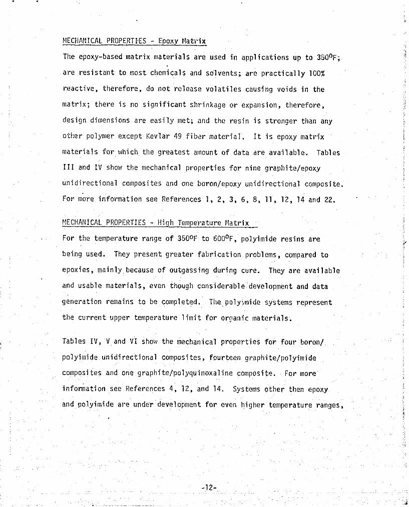
MECtJAP!ICAL PROPERTIES - Epoxy Matrix
Tlie epoxy-based matrix niaterials a re used in applications up to 3S0°~;
a r e r e s i s t an t t o most chemicals and solvents; are p rac t ica l ly lGO%
reactive, therefore, do not re lease vo la t i l es causing voids i n the
matrix; there i s no s ignif icant shrinkage or expansion, therefore, I
design dimensions are eas i ly met; and the resin i s stronger than any ! I
otlier polynier except Kevlar 49 f i b e r material . I t i s epoxy matrix
materials f o r which the g rea tes t amount of data are available. Tables I I 111 and IV show the mechanical propert ies f o r nine graphite/epoxy
unidirectional composites and one boron/epoxy unidirectional composite.
For more information see References 1 , 2, 3 , 6 , 8, 11, 12, 14 and 22.
MECHANICAL PROPERTIES - High Temperature flatrix
For the temperature range of 3500F t o 600°~ , polyirnide res ins a re r"'
being used. They present greater fabr icat ion problems, compared t o
epoxies, mainly because of outgassing during cure. They a re available
and usable materials , even though considerable development and data
generation remains t o be completed. The poly?,mide systems represent
the c ~ r r e n t upper temperature l im i t f o r orpaiiic materials .
Tables IV, V and V i show the mechanical properties f o r four boron/
polyimide unidirectional composites, fourteen graphite/polyirnide
composi t e s and one graphi te/polyquinoxal ine composite. For more
i n f o h a t i o n see References 4, 12, and 14. Systems other then epoxy
and polyimide are under development f o r even higher temperature ranges,
-1 2-
. *

but are s t i l l i n the experiniental stage for use w i t h advanced f ibers .
These polymers are: polybenzimi dazoles, py~rones , polyaryl sul fones ,
and polypl~enylene su l f ide . '

T A N € Ill D~LC~(~I~,~CAL rI;CrLfiTlLS cr CRAI I ITL/LPOX'I CCI!~OSITCS
( I~PICAL Y A L O L ~ )
REPRODUCIBIZITY OF THE -14- CINGNAL PAGE TS POOR


TABLE V MECHANICAL PROPERTIS i3F GRAPtIITE/POLY IllIDE COMFOSITES
(TYPICAL VALUES)
G~4Pl i ITi I GfiArl~ITt/ GPi.il11TEl GFi,rI,ITC/ tlTd~rI4ITC/ TrJP~'"rl GKAfliITCI G ~ , - I ! I T E I ,-rd.r,l,c~ r t i ~ b II.ILL FLLI 1I:ILL I'CLI 1:'ICt FiL \ If ICE L I : ! K L \ 1f'ICf rCL1 IE'IGE r c ~ y ~ p l u t rtLY CO. ,!OCI'L$ 11/SL703 t W'bR I I/5C70: t'C.t'LS I tC!:CR 1 :';>L7C3 FGEI;AftITE CCLfiTAtLGS lITS/ 11:'Sl 56 710 11 1 C-,LL tL!aSA!tTO 1 t S T I I/'L;i03 Ii/SSBS-6?24 t i:,SE!.TO 1 ~ / S E 703 5~ KS-€234 I'C:I'Y~TO
YCISA:I'~O Y~LY,I,;O fO/>L 223 I'C55,IltTO tWIaSA!tiO
' LXI -bF OIfiCCTIGtl 9' 0' - 90" - t45' 0. 0' 0' 0'
110 "J7KGTTh:t,~~h 7 i T 165.45 ' 61.4 2% 1 1 5 . ~ I
GCljeF ) 11.7 146 65.6 113.8 I . _ _ 1 ?
-. -' FLLX. I:.ibLI;S ;7'F 21.7 ,::s i ) 600°F 12.3 16.6 '
. --;L:.SILL 77'F , S7irEiaGif1 (Ksi ) 55JaF
,'TL:AILt kdLCLIJS 77'F ' 5 1 ) - ,-.-N. STKticGTli 77'F . -. -,'.s?J- 2--
,'f LC:.$. I:uuULbS 7?"F -u i bG-' F L U . STRLLGTH 77'F ;&i )
157 104
20.1
10115 -- lb.9 I
7.1
! I I . - I G d - F i t : , j l L t I 1.26
I s H . G T r ( C s i ) Z>- TL!SiLE 77°F 1.35
:L;W~AS~\ . '- I , ?A:L ShCAIZ 77°F 10.24 ; CCr;LLS (i:si)
6.27 .
550°F I .436
1,'4.4 105.3
20:5
B.E~ROktUCBI.L.ITY OF THE ORICXNAL PAGE IS PQQE
TABLE V I i4EC;dAMICAL PROPERTIES OF GRAPHITE/POLY IbII DE AND POLYQUINOXAL I N E COClPOS ITES
( TY P I CAL VALUES )
- 36.5
21.5
6.4
142
-
. .
-
173.2 161
4.59
3.58
8
i
-I

MECHANICAL PROPERTIES - Typi ca1 Fiber Properties and Trade tjames
Graphite and boron reinforcenlents are 'considered d i rec t competitors
intl many respects. Depending on the specif ic appl ication and fab-
rication problems each material has i t s place. The only variation 1
I obtailiable in boron f ibers i s the f iber dianieter. Boron Fiber tape $1
! >,
and broadgoods prepregs can be purchased w i t h boron f ibers having r: q I.
tlismeters of 0.004 or 0.0056 inches. There i s a weight saving ad- t
1
vaAtage ahen using the 0.0056 inch diameter f ibers . The tungsten
cers'ter i s the same diameter i n both f ibe r s , therefore the overall h 1)
ty i s less f o r the larger fibers. Graphite materials are
available in several types ranging from low modulus to u l t ra high
modulus properties. A s the modulus increases the tens i le strength
decreases. T h i s i s due to the f a c t tha t the modulus increase i s a
function of the percentage of f iber graphitization. Crystal l ine e
graphite has a higher modw'us than arnophorous carbon. By the same
token, as the percentage o f graphitization increases, the f iber
tensile strength. is more dependent upon the. bond strength between
crystals , which i s less than the tensi le strength of amophorous i i
carbon. Tables VII and VIII show the typical properties o f a l l the
types and the vendor trade names for a l l types respectively.
TABLE VII TYPICAL GRAPHITE FIBER PROPERTIES
,**.,re-
' bee d$-S ' Type tiN-5
UTS, ksi 400 to 450 350 t o 400
p. 1b/in3 0.0630 .-

TABLE VIII GRAPIIITE FLBERS CLASSIFIED BY TRADE NAPiES
w :.~~L'Lus, LGV r e ~ ~ T R A HIGH PWZULJJS, !iIC!i ST ?.!.ZTH
P C , ! - -- Hercules Type A-S Hercules KC-S !iercules N4-S CeLanese Celion CY-70
coWtsulds m-s C ~ r r r t r x l d s T ~ E .4 Kcremite Type I11 >!adnor Type I1 Yodmr Type I
Fortaf i l 5-T Polycarbon T For ta f i l 6-T
Hitco iG.]G-~O

TADl-E I X
COMPOSITLS COt4PARISOII PROPERTY DATA
ALI;:C,I I:L!:? (2024 - 781)
-
. - hORO:l/ hl-I"' : ',L!.!
it:.: tT.Ci1::
52013/T300 KLVLAR - 45 I I*!ATLfi I kL i SLCi CliPLY ULSIG:ATiGiI 1359 - 2GS
5565/4 SCOl C!iI'LY i C G 3 - 2 G C
ll:!!oIEECTIOifhL I - Ii/?R?.CO ' 7-A /+PC0
F13 i2 ORIEIITATIC;;
F T8ERjRCSIii
USIDI!lCC7IO~IAL
GRAPIIITE/ EPOXY -
FLC:1:LRAL t:SCL'LtiS ( lCU) 7.9 7 .0 11 22 - , I - I. - ;
zj.; I GU;'Q:IT
Ili:.STLZ STPCi+STII (PSI) 223.000
ITLi iSIL i lXLULliS ( 1 ~ ' ) C.7
U:lIb1RiCTIO::kL
S-GLT\SS/ EPOXY
'!k/i~ii2
UhI DI2rCTICf:AL
BORc:l/ EPOXY
UIIlDIRECTIG:!r\L
E-GLt\SS/CPOXY (ALU:CI::III't SHEET)
, iC"i' ifSS I v E
3;:
~ ~ I I D I R E C T I O ~ A L
ORGkl\lI C / EPOXY
i-L! {C?.?L STRC::PIT~I (PSI )I 230 ,OGO 2C0.000 95,000 ' 295,000 -
- 161 . G X I E4.G.CO 192.000
30
1C5,030
5.7 20
-
64,030 343,Or)O 120,000
175.000 247,030 I 13 23.5 10
-
/i\ SIiDRT B W SHEAR
&, BASED orr loo sp.vos.
SO ,COO I 40*0m IST:~L:,J~~~ (P51) I 9,000 .
3. , 10-6*
I
10,COO
1.0 X lo- ' (L)
12.7 r 10-6 (T)
0.055
2C4,000
Ii;iE%Lil?!I;;irh' SllEt?R STEEit;T!i (PSI 1
CC1EFFECIE;,T GF TliEfil!f,L EiP;:;s?G'{ ( I:,/ Iri/'F)
bi:,sl TY ( ~ 3 / I?)
FLY/SI!tET T!I!C!::;ESS( 18)
S T X L \;I Xii ( 1:;)
UFPi? TEI :PCRATURE G,::&E ( O F )
Y;ITER!AL COS'I (s/YD')
30,000 (s!iFilR) * -
13.) 10-6
G.100
353,000
8,000
1.1 x l o - b '
0.0072 1 ,010- .012- .o16
17,800 /j\
- 2 X 1 ( L )
7 1 0 ( T )
12,000 /i\
1.1 x l o - 6
- < 20
600
135.00
15,0170
2 . 3 X ( L )
10.6 x ( T )
0.050
0.0055
- 12
400
35.00
0.050
0.0045 - 0.013
- < 12
3 50
9.00 A
0,072
' 3 ,0075
- 12
300
36 - 18
350
1.30/LB.
0.0725
0.0052
- r 12
4 20
53.00 .
0.072
0.01775
- < 1 2 , -
300
7.50 a 2.80 -
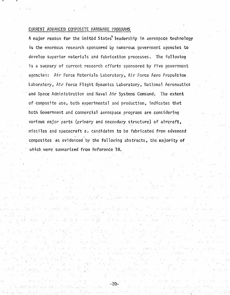
CURRENT ADVANCED COI:POSITE IlARDkiARE PROGRN.1S
A major reason f o r the United s t a t e 2 leadership i n aerospace technology
is the enormous research sponsored by numerous government agencies t o
develop superior materials and fabr icat ion processes. The following
i s a sunimary o f current research e f fo r t s sparlsored by f ive government
agencies;: Air Force Eatcr ia ls Lat;orstory, Air Force Aero Propulsion
Laboratory, Ai r Force F l i g h t Dynami cs Laboratory, National Aeronautics
and Space Administration and Naval Air Systerns Com~rand. The extent
of composite use, both experinental and production, indicates t ha t
both Governrrent and comrcercial aerospace programs are considering
various major par ts (primary and secondary s t ruc ture ) of a i r c r a f t ,
missi les and spacecraft a , candidates t o be fabr icated from advanced
composites as evidenced by the following abs t rac t s , the majority of
which were summarized from Reference 18.
- 20-

Aircraf t Systerns Appl i catiotis
Boeing Ai rc ra f t Co.
737 Composite Spoi lers - Phase I - Graphite/Epoxy Phase I1 - Advanced Design Using Flixed Fibers
The f l i g h t spo i le r s of the 737 Airplane were selected as components to advance the use of Graphi telEpoxy materials f o r s t ructural appl ica t ions . Spoilers were developed with the ali~minum skins replaced by Graphi te/Epoxy and the aluniirium end r i b s rep1 aced by f i berglass. ,The Graphi te/Epoxy spoi l e r i s 15 percent 1 igtiter than the a1 1 alurninuni productiori spoi ler . Plans are to fabr icate -and i n s t a l 1 108 Graphi te/Epoxy spoi lers on 27 a i r c r a f t f o r f l igh t service through- out the world. Phase I1 objective i s to a r r i ve a t a more advan~ed version of the spo i le r with niaximum ef fec t ive u t i l izat ion of csinposite materials and a core such as Nomex o r PRD-49 to replace the aluminum honeyconib core.
GENERAL DYI'IHIICS - F-111 Horizontal S t ab i l i z e r - Boron/Epoxy Skins on A1 Honeycomb
A f u l l -depth sandwich was chosen f o r design development. llajor fac to rs w h i c h led t o t he se lect ion were weight, complexity comparisons and consideration o f the previous development experience with the scaled version of the component. The component consisted of boron/epoxy skins; fibel-glass spars and honeycomb core; and titanium root r i b , pivot f i t t i n g and t i p r i b . Both s t a t i c and fa t igue t e s t coniponents were bu i l t . S t a t i c f a i l u r e occur~ed i n . the attachment area i n the region of the pivot f i t t i n g a t a load of 136 percent of the l imi t design s t r e s se s . The p r imry cause f o r f a i l u r e vias found t o be a design deficiency i n the a f t spar t o hub f i t t i n g jo in t . In the fa t igue t e s t , four lii'etitrles of the simulated F-111 horizontal t a i l loading spectrum were succ~ssful ' ly applied.
4 -- Advanced Composites Technology - Fuselage Comnonents - Boron/Epoxy. Grt-phi te/Epoxy*
Boron/l\luwinum B~ron/high-temperature- p l a s t i c and molrred p l a s t i c matrix composites
The component selected t o be bu i l t f i r s t in t h i s prograni was an F-111 a f t f ~ x l a g e sect ion, 160 inches long, 48 inches deekb and 36 inches wide. The fuse1 age component was.,prirnari l y of graph4 kelepo) y construction, h u t a1 so incorporated boron/epoxy and boron/aluminum i n b c t h tape and molded foriis. A comparison of the composi te t e s t section with the exist ing metal section reveals t h a t the application of composite material rcsul t s i n a weight saving
; of 19 percent. i i For the second component of the fuselage program, the F-5 center section I was chosen. A 26 percent weight reduction was achieved with t h i s component.
! I
-21 -
-- -- -----

Con~posi t e Configured Light Weigllt ~ i ~ h t e r Aircraft
A 160-inch-long t e s t cornponent was fabricated and tested to destruction. Con~posi te material systeais of graphite/epoxjl, boro~~/epoxy, toron/alun:inun~ and glass/epoxy \:rere en~ployed. tlaxin!um irse of composites was used through- out the structure, w i t h b o t h skins and substructure being considered. A s t a t i c t e s t co~ponent was detai 1-designed and fabricated. Fourteen sub- dssel;,blsies of frames and panels were fabricated atld assetxbled into a 920-pound cor;,ponent us-in5 460 pounds of corr,posi t e niateri a1 . A t ~ e i g t t t saving of 18 percent of t!ae counterpart aluminum structure was cbtained. S ta t i c t e s t of the part lncluded loading in bending viith sir~ultaneous application o f internal pressure. The coEponent sustained 130 percent of design l imi t load.
Winp and Empennage-to-Fuselage - All advanced ~ e t a l and Attiichnient Fitt ings resin matrix con:posi tes
The f i r s t phase i s t o establish the f eas ib i l i t y , extent and design concepts
1 f o r using advanced conlposi tes f o r attachn~ent f i t t i ngs . The second phase t; d e~ons t r a t e th i s capability through ful l -scale s t a t i c and fatigue i: t e s t s of a typical wing root joint. The wing root joint used i n the I
u' rl.icDonnel1 Douglas F-15, a high performance je t-f ighter , has been selected as typical of many sin;i 1 a r ai rc raf t altacl1n:ents. Twc subcontractors were chosen t o support the development 'of f i t t i n g t y p ~ s : Goodyear fierospace, u t i 1 i z i n g i t s expei-ie'nce vri th con~pression 1x01 ded corcposi tes , t o develop graphite/epoxy channel type bathtub f i t t i n g s , and the Harvey A1 urninurn Co. t o investigate composite reinforced forgings.
GRUMttAN AEROSPACE CORP . F-14 Hori zontal ' ~ t a b i 1 i zer - Boron Epoxy a
This program designed, fabricated, and s t a t i c tested an a l l movable horizontal stabi 1 i zer uti 1 i z i ng boron/epoxy materi a1 for skins and portions o f the suLstructure. .
F-14 Airplanes with boron horizot:tal stabi 1 i zers are now in squadron service a t Mirarilar Naval Air Station, Calif . The weiglit saving i s 182
- pounds per Aircraft.
Composite \ling Box Eeam - Graphite/Epoxv, Boron/Epoxy and Bcron/Aluminum
Frogram included the design, analysis, mats4 +a1 characterization, process development, coniponen t fabri chti on and t e s 1 The coxponent succes-sful ly completed both s t a t i c and fatigue tes t s .
-22-

LOCKHEED AIRCRAFT CORP, .
C-5A R i g h t Hand Inboard I S t a t i c Test Leadina Edce S l a t s - 1 Fatiaue Test ' Boron/Euoxv
1 ~ c c e i c r a t e d Service Test 10 Production Gperati on31
A i rcraf t
This ksrogram includes the design, fabricat ion and t e s t of th ree inboard leadintj edge s l a t s and incorporation of 1C production ; l a t s on operational a i r c r a f t . The th ree t e s t a r t i c l e s t:ere u t i l i z ed in a s t a t i c ul-ti~viate strengtli t e s t , a f a t igue t e s t and an accelerated scrvice t e s t .
I Tile s l a t has a platform area of 65 sc;. f e e t and a t o t a l weight of 190 l b s . , 21 percent l e s s than t h a t of tile aluriiinuni s l a t i t replaces.
During s t a t i c t e s t ul tinlate loading was rain'tained f o r 80 seconds, a f t e r \~itiich a f a i l u r e occurred on the outboard end of the s l a t . The second s l a t was ins ta l l ed on a C-5 a i r c r a f t and f l i g h t tes ted with no problenis. The s l a t pias then i n s t a l l ed on the accelerated service t e s t a i r c r a f t f o r an operational exposure pericd of 6 nionths.
The th i rd s l a t i s undergoing t e s t s t o demons t r a t e fa t igue endurance under cyc l i c loztding. These t e s t s wil l extend t o a span equivalent t o four a i r c r a f t 'I ifetictes o r 120,000 f l i g h t hours.
C-130E Center Wing Box ( 3 ) 1 t,?st, 2 f l i g h t - Boron/Epoxy
Three conventional center-wing boxes of the C-130E design wi l l be fabricated and reinforced i n the spanwise direction with unidirectional Boron/Epoxy composite. About 500 Ibs. of Boron/Epoxy wil l be bonded t o the skins and s t r i nge r s of each wing bcx t o reduce s t r e s s levels and increase fa t igue l i f e . The aluoiinum \\ling box weighs 4,800 Ibs. and the Eoron/Epoxy weighs only 4,2CO lbs . Eoron/Cpoxy reinforced box n~ust have a fa t igue l i f e of 40,000 hours. One panel was tes ted fo r s i x l i f e t i s c s and had a residual s t a t i c s t rength of 109 percent l im i t load.
L-1011 Fairing Panels - PRD-49 Fi ber/Er,'oxy Composi tes/Fiomex H / C Core. 4
The PRO-49 f a i r i ng panels a re t c be service-tested on 1194, Eastern Air Lines and Canada Ai rc ra f t t o represent a variety of route s t ruc tu res and service cbnditions. Test wi l l be a 5 year scrvice evaluation.
. The cc~ponen t configurations f o r fabr ica t ion consis t of seven v:i ng-to-body honeycorxb sandv:ich panels (one for s t a t i c t e s t ing and s i x f o r ins ta l l a t i on on a i r c r a f t ) , s i x wi ng-to-body laininate f i 1 led panels, and s i x center engine honeycon;b f a i r i ng panels, each app rox i~a t e ly 60 X 60 inches i n s i z e .
The s t a t i c t e s t pa r t f o r the wing-body f a i r i ng has been fabr ica ted and successful l y t e s ted .

A-7 Speed Brake - Graphitc/Epoxy
The A-7 speed brake was choseti as d demonstration ccniponent for con!posite n:aterials because i t i s large and highly loaded, b u t i s not priniary structure. The specd brake i s about 9 f t . long and 6 ft. wide t!i.tIi the chines extended. The total predicted wcigllt of the graphite/epoxy' speed brake i s 73.9 por~nds compared to 123.4 pounc?s for the xctnl speed brake. This represents (1 40 percent weight saving.
f.iCDOPii.IELL DOUGLAS C O W .
F-4 Boron Rudder - Goron/Epoxy
Program eras t o der;;otistrate the fcasi bi 1 i ty of Poron/Epczxy coi~posite usage in f l i gh t structures. Fifty rudders weve bu i l t and have been in service f c i . ;1pproxirr1ately 2 years. The Boron/Epoxy rudder i s 35 pel-cent l ighter than the a1 umi nun1 counterpart. The rudder has been successfully s t a t i c tested to 310 percent design linli t load before fai lure .
F-15 Composite f.!ing - 9 Ribs + 1 Spar Grapl~i~te/Epoxy - IEari~ico 5208/ All tlat and Tee Thornel T-300
Stiffeners I /
All other components Boron/Epoxy
This program tias concerned v!ith the design, manufacture, ground t e s t , and f l i g h t t e s t of an F-15 wing 'torque bcx ut i l iz ing bor.on/epoxy and graphite/ epoxy. con~p~si tes. In i t i a l design w r e progressi vely eva1 uated and developed throush subco~rponent and fu l l scale s t a t i c and Fatigue t e s t s .
.. F-4 Boron/Graphi te/Pol yimide Rudder - Boron/Pol yimi de and Graphi t e Polyimi de)
The program bias t o design, faDricai:,e and t n s t a polyinide olatrix coirposi t e rudder. The process was developed 2nd the rudder successfully fabricated. I t was s t a t i c tested to fa i lure a t 400 percent of design l i c i t load.
A-4 tlori zontal S t a b i -- 1 ator - Harrnco 5206 Resin/Graphi t e 'Type I1 Fiber
Frograni demonstrates use o f iraphi te/epoxy in a i r c ra f t primary structures. One s tab i l izer fai led a t 50 percent l imit load in kajor joirt. to fuselage area. Redesign ~f second s tab i l izcr i s in progress. Estirdated \:eight saving i s 20 pertcent.
A-4 'l!in~ Landing Flap - Borofi/Epoxy - Graphi te/Epoxy
The principal objectives of th i s program viere t o demnstrate the weight savings possible with the use of advanced con~posites and to compare the advantages of boron/epoxy w i t h cjraphi te/epoxy i n the same application. The composite flaps arc 6 f t . i n span and 2 f t . in chord and have a constar~t cross section about 2 inches deep a t the leading edge.
REPRODUCIRILI'IY (!S; 'I'H r..
ORIGINAL PAGE IS PO011

!IOKTIlI!QP CORP.
F-5 Ilori zorital Stabi 1 i zer - Graplli te/Epoxy
The con:posi t e tiorizontal stabi 1 izer , dcsigned to be a f l iglit\~orttly primary structure and fu l ly intercllangeable with an cxis t i ng metal s t a l i 1 i zer , fiss
i successfully conipleted a 16,000 hrs. ( 4 lifetiriies) fatigue t e s t . The stabi 1 i 2cr exhi bi ted simi 1 a r deflection characteristics t o the production :,;eta1 s tabi 1 i zer ant1 displ ayed nore t h i i t ~ adequate fatigue 1 i fe . ;lo de- gradation or f a t i aue dar,;age wiis detectcd e i ther during or a f t e r the t e s t .
F-5E I r a i l ins Edue Flap Graphi te/Epoxy , Boron/Cpoxy /\-911 f<udcier PRD-49., E-Glass and Hybrid
The F-5E t r a i l i ng edge f lap and the A-9A rudder were selected as den;on- s t ra t ion co~ponents. Preliminary conceptual studies fo r the coaponents t;a\re been cor:l~leted. I'relirtiinary design o f these cocnonents i s currently in prolress . FaGri cation processes f o r these components, con\~entional autocl aye, pl aterl press, and vacuulli bag, uti 1 i zing aray.l.ii telepoxy , boron/ epoxy, PRD-49, E-glass and hybrid materials are being co~?srt?d for cost reduction potenti a1 . RGCKWELL IiiTERNATIOI~IAL
F-100D Wing Outer Panel - - Upper and Lower Skins - Eoron/Epoxy
The structural eleriien ts chosen were the upper and lower skins of the F-100D wing panel. The skin i s approxiriiately 20 f t . in span, with chord dimensiot?~ of about 5 fee t a t the inbclard end and 2 f i . a t the )ringtip. The panel thickness varies from about 1.6 inches a t the inboard end to 0.1 inch a t the t ip . Estimates based on preliminzry design drcwings indicate a 21.9 percent weigi~t saving over the ccrsparable a1 uminuni skins.
I t was expected .that current cure cycles r~ould not be satisfactory because of the 2xotherm reaction resulting from the very thick sections. A testing plan was establistled to develop the proper cure cycle for the lower exotherm reaction'
B-1 Boron-Reinforced 'onaerons -- - Boron/Epoxy and PlastSlock 731
- This prsgram i s t o design f a t r i ca t e and t e s t dorsal a n d lower longerons se ' lectivel:~ reinforced w i t h boron/epoxy f o r the a f t fuselape of tile 6-1. This re i n forcc~ent i s necessary to provide aeroelasti c s t i f fness for support of the t~orizortal s tab i l izer . They are scheduled t o be installed on the f i r s t B-1 a i r vehicle. The up17cr dorsa? longeron i s 47 1/3 fee t in lencth. The main fuselage loner lonaerons are 27 2 /3 f ee t in length. The lower in- board longerons are 19 112 feet long. Thz boron/epoxy i s bonded to the nietal straps during the cocuring operation, and B. F. Goodrich Plastilock 731 was selected as the bonding adhesive. This selection was based on good lap sheat- strength, high peel resistance, and good cure flow characteris tics.. 441 p~unds o f boron/epoxy resul ts in a weight reduction of 11% pounds from the a l l metal design.
-25-
.- -
HELICOPTER AND VTOL SYSTEtiS APPLICATIONS
GELL - U t l - 7 Tai 1 Rotor Dri vr! Shafts - Goron/Epoxy , Graphi te/Epoxy
Syster;is analysis indicatcrl a weight saving of approximately 28 percent. Tlie driveshaft has a l e n ~ t h betneeti supports cf 97.25 inches, and would be required t o sustain an ultinrate torque of 20,000 incll-pounds. Tvro fu l l - lcngtit boron/epoxy and two fu l 1-1 en5 t h graphi tc/eno;ty dri ~ c s h a f t s t!ere f a b r i ~ a t c d by lJllittaker a n d shipped t o Bell for structural and dynaniic grownd tests .
COE J i4G CO. \;ERTCL D I V . - . liLii [k in Rotor Syncllronization Stiaft - Co~binations of glass,
graphite and PRD-49 filaments f
Becatise of a problen; encountered in obtaining adequate lo\! velocity inipact resistance, the potential weight saving had been seriously eroded by ttie increase i n t u b e weight fror;i 141 pourrds, for ttle a1 7raphitc/epoxy slystem, t o 233 pounds fo r the gl ass-graphi t~ lepoxy system. , resulting approx- imately 12 percent eight reduction over the a l l meta'i . ~ s i q n laas not considered to be cost effective i n viewof tile potential f i e l d probierns involved.
C11-47 Aft ?!sin Rotor liGB Blades - Borirn/Epoxy
The program !,as t o d~ve10p the techrrology for the design and construction of the bol-on/epoxy blades. The progriiel was conipleted and no f l i g h t restr ic t ions were found. The blade performarice arid stabi 1 i ty was excellent. Both the quantitative and qualitative impressions developed are extremely encoltraging for t he boron blade. A filinimuiii increasc of 3500 pourrds in rotor 1 imit gross weight capability in forward f l igh t was projected for the C11-47C helicopter wi th Boron t 1 ades . IIODEL 222 TILT ROTOR SYSTEl i - tiybrid of Fiberglass/Epoxy and Eoron/E~ xy
A key factor in the development of tkc I{odel 222 t i l t rotor tiytrid advanced corl;posi te-propel ler system was the use o f rnatcrials with a high ra t io of fa t igue strength to e l a s t i c modulus. The ab.;i t y to conitiine and t a i l o r the fiberglass and boron composites to at ta in desired structural properties was a sign;ficant factor in the i r selection. The design, fabrication, and 6
fatigue tes t s are cotcpleted. The feasf b i 1 i t y of using hyhri d co~ilpos i te fibers i n a single system was dcnlou:strated.
!
-26-

CM-546 Tail Cone - Hybrid of boron/epoxy and a1ut:iinum
Phase I study co~~firmed the fqct t ha t bsrmlepoxy - reinforced s t r ingers can be fabt-icated and that tile-ir s t a t i c and fatigue strength i s adequate t o n~eet the requiren~ents of the CII-54E. Phe boron/epoxy reinforced ta i 1 cone was fabricated and Fokker bond ultrasonic tested. Tlie installed t a i 1 cone was ground c11ecl:ed and found t o be 10 percent higiler on vo-ti cal bendi ncj f re~uency than the previous pro- duction a1 ui:iinum reinfoj-ced ai rfrape. F1 i ?tit: tes ti tig c0nf.i rmed tha t the t a i 1 cone v:i t h the boron/epoxy-reinforced t a i 1 cone el in~i nated any s-i gni f i cant dpnanii c coup1 i ng betvrcen the rotor and ai rfran;e . C11-54G TALL SKID G E A R TUEES - Eoron/Epoxj~
Uoron/epoxy tubes were df?signcd to rep1 ace the consent i onal s~!aped a1 u- minutti ~ c ~ b c r s of the Cli-54C t a i l skid Gear. Tv!o ser ies o f t e s t s v:erc conducted and shokred the tubes to have a 50 perccnt rrargin or" safetjt over the design load requiren?ents. The tubes were installed on the helicnpter and released for service.
S-61 Tai! Rotor Blades - lfybrid of Ooron-glass/epoxy rJ
The purpose of the program was to f l i gh t t,est a vi ta l dynamic component made af boron con:posite. The t a i l rotor blades of the S-61 helicopter was selected. ii fu l l s e t of f ive rotor blades was whirl-tested a t rated speed and found t o be flightvrorthy. A fu l l s e i of boron-glass/epoxy blades was then f l i g h t tested.
5 - 6 1 Drive Shaft - Boron/Epoxy -- The higher structural efficiency of boron/epsxy compared with present nietal
1 - shafts pr.om:'ses vrcight savings of n:ore t h a n 50 percent in shafting. Tile ta.41 rotor drive shaft systccn for the S-61 a i r c ra f t consists of a sandvricb 'i
structure in which t ~ o boron lail~inates vrcre separated by a low-density core o f foan or honeycomb. P.n integral end f i t t i n g in whic!~ the fikcrs continued into the end vras developed. Testing of the integral end f i t t i n g slio~ted i t
, t o be structural ly sound.
CEROJET GCIjCRAL CORP.
Fi 16;ient-Llound Press "re ' ~ e s s e l s --. - Cryrlseni - c Service - Boron/Epoxy
.Type 304 corrosion resis tant s teel ( .OO6 inch foi 1 ) v i i t h karon/epoxy filament 'ove~vind. Tlie foi 1 1 iner i s cryogenically strcsscd for s t ra in
conlpatibility. The vessels displayed very low biaxial s t ra ins and high '
strength t o weight ratios. Such lovr s t rains permit h i g h s r cc i f i c sjrength rnetal l iners t o work e las t ica l ly up t o the ultil~iate s t ress rsf the boron filament vlit~dings.
EOEIIIG CO. -- Pii s s i l e Interstage Structure ---- vri tI1 Iiat St i ffeners and Rings - Graphi te/Epoxy
The objective of th i s pro?ran; \.:as to inves t i s a t e fat rication pl-ccc-sses and t h e i r relationship to design, fabrication a n d t e s t o f Iliglr-rr.odulus ~rap! i i te- reinforced con:posite structural elcn~en ts representati ve o f s I:i nutentan 111 mi s s i 1e interstagc s t ructure. The cyli ndri cal elements were tested under cotxbined axial ccmprcssion znb external pressure and developed 200 percent of design load. The various ternii nal jo in t configurations demonstrated that adhesive bonding can be used to transni t lligli 1 oads into graphi telepoxy co~pos i t e 1 ami nates. lfuv~ever, tlie cokesi ve strength of the cor-posi t e ateri rial was tile joint- strength limiting factor rather than the stren@-th of the adhesive i t s e l f .
Reinforced Pressure vessels - PRD-49/Epoxy with Eoro~/Epoxy
Cocs t ruct i on has been evaluated with prcssuri zed ' f i 1 ament wound cyl i nders and s~ilall pressure vessels with good success. Advancement of the technology to applications of completely wound pressure vessels of f1 ightvreight constructior: i s 11endi.n~. One diificultj l encountered with the material, i . e . , i tsa relatively low specif ic conpression s t r e n ~ t h , has pron;ise of being overcotne by combining the P1:D-49 fibers in a sandwich - conlposite construction having the outer layers of the laminate reinforced with fibers of higher com- pressive strength.
Shuttle Titani urn C l a d m n / E p o x y Shear bleb -- Fabricate and t e s t titanium clad boron/epoxy lanlirlate &is a shear v!eb with vcr t i cal s t i ffener niembers 1 ocal ly rei riforced t l i th boron/epoxy 1 amina te.
+. Also sandvci ch web configuration with titanium clad borun/epoxy facings. Prcl irninary niaterial properties studies corcpleted. Sections of f l igh t - weight shear web construction fabricated and s t a t i ca l ly tested.
Shuttle Orbiter Reinforced Fuselage Frarre - Boron/Epoxy -
Progranl i s t o evaluate the feas ib i l i ty o-F designin! a Space Shuttle Orbiter t i tani urn fuse1 age frarce reinforced v~i th boron/epnxy coirposi t e 1 ami nates. Eoron/Epoxy-rei nforced frat?? i s app t-oxirrately 25 percent l igh ter than an olrtin:ized all-titanium f r a ~ e . The paterial that was selected fo r the desil;n of the metal frar:e i s 6 A 1 - I V titanium.. The conlposite~reinforced counterrart will incorporate the use of Rigidi t e .5505/4 laminate. lktalbond 329 i s the adhesive for asserrbl ing the various reinforced frame con;ponents.

GENERAL ELECTRIC CO.
Reen t ry Vehi cl e Conlpos i t e Frus trutn - Boron/Epoxy (Fi 1 arnent-wound)
The objectives were t o develop a design, perfect fabrication techniques, and t e s t an advanced con:posite structure representative of a Pcenlry vehicle configuration which incorporates an insulation systenl to rrxi ntain the load-carrying s t r u c t w c within acceptable strength to tenrpcrature 1 i i t ~ . The con Figuraticri chosen incorporated an ahlati vc- type nose cap, a Dcronlepoxy filarnen-t - wound conical frus.tum structure \.rii;li an overlaid state-of-the-art therrral shield and an a1 utl i num heniisphere s t ructure v~i t h a bonded theni!al shield.
GOODY EAR ,4EROSPACE -
Paraboloid shaped antenna of sandwich type constructiori having a1 upinurn core and graphi te/epoxy fzces. Graphite/Epoxy feed support s t ru t s were fabricated. The 30 inch di anleter antenna 1;tss completed, thermal cyclic tested and exposed to ul t raviolet arid ganxa radiation. All objectives o f the* progralll were niet .
Grunriian
Tubular S t ru t - Shuttle Thrust Structure - Boron/Epoxy - A pin-jointed tubular t russ , thrust structure replaced a t i taniurn tubular t russ . Prcgram completed t ~ i t h or~e third scale truss ~nembers and segn~ent of the assembl:d truss. Str~lcture failed a t 121 percent of ultimate design load w i t h a 32 percent weisht saving.
Je t Propulsion Lab. b tl
8
Fi 1 aaent-I~iound Rocket Motor Chambers - ATS Sate1 1 i t e - Eor~n/Epoxy --
Program t o design, fabricate and t e s t advanced corpcsite rocket ~ ~ t o r chamber for potential replacement of the 6Al-4V applications on the ATS Technolagy Sa te l l i t e . Charcbers were successfully fabricated and passed the hydrostatic proof t e s t s .
I:CC@F!IIELL DCLJCLAS ASTROI.IA.UTICS CO. HEST -- Shuttle Landing Gear Door Assenibly - Graphite/Epoxy - Alc~inuni Honeycomb C0r2 -
Sandwich
Original ly designed r i b-s t i ffened t i tani urn panel Kas selecl i vcly reinforced with graplii,tc/epoxy laminates. The subsequent redesign i s to use a sandwich v l i tli alunii n u m honeycomb core and graph-i telepoxy faces. The design, specimen t e s t and fabrication of landing gear door segrnents are corcplete. S ta t ic a n d cnvi ronmcntal testing are pending. ]R~RODTJCIBILITY OF THE
-29- ORIGTNPL PAGE IS POOR

II!ORTHROP CORP ,
Tubular S t r u t - Graphi te/Epoxy and Glass/Epoxy
Design consisted of a platfonn support s t r u t elenrent L I ~ t l~ cc~binat ions of glass clotti and Thornel 50 graphite. The program i s co~p lc t ed . Light weight f i t t i n g s were designed. There was a 46 percent weight saving on the tube and 25 percent 011 tlie end f i t t i ngs .
Cr;/o.clcnic, Support Struts - Goron/Epoxy
Design consisted of 'a network of pi n-endcd strirts connecting an insulating s t i ro~~d to the for\;~ard s k i r t of a tank. The follovring conclusions resulted frorii t h i s ~rogr-am: (1 j boron/epoxy i s an excel lent ii:aterial fo r structure requi ring a lo^ thermal conductivi ty and tiich sti.ifness o r stabi 1 i ty under eomprcssi vc 1 oad; (2) no serious mechani cal or physical property defects were rioted in the cryogenic temperature reginle; ( 3 ) the 10% te~pera tu re tolerance of adliesi vely bonded structures to eccetitri ci t i e s requires fur ther study of adhesive bonds f o r cryogenic aqpl ications; and ( 4 ) t i tani urn metal skins in 1 ieu of s tee l are desirable for low-temperature reinforcement of boron/epoxy because of a pood coefficient of expans i on match.
TR\i/SYSTEM DIV.
l~?odel 35 Spacecraft S t ru t - Boron/Epoxy
In i t ia ted by TR!4 Systems t o further the state-of-the-art of 1ightv:eight structures. Effort was to design, fabricate, and evaluate boron/epoxy c o ~ p o s i t e s t r u t s as a subst i tute for aluminum counterparts used iri the Idode1 35 Spacecraft. A1 t t ~ o u y h the end f i t t i ngs and attaclnments were n o t nptimized, a weight savings of approximately 30 percent was realized over the a1 unii nurn counterpart.
Pi onecr 10 Spzcecraft Tubul a r Struts - lloron/Ep~xy - The -tubular support s t ru ts were designed to carry pure axial corr,pression and tension loads and were designed !.!i t h t i tani urn clevis type end f i t t i ngs for p i n attachment to the platform and adapter cylinder. The stepped end f i t t i ngs
. were bonded to tkle tubular section. Prototype s t ru t s successfully sub.jected to a ser ies of t e s t s including coc:pression and tensicn cycling t o verify the analytical predictions. Production s t ru t s have passed a1 l qualification t e s t s and eere flown on the Pioneer 10 Spacecraft launched in March 1972.
- 30-

Extra-J{igll Frequency (EHF) Rntcnnas - Graphi te/Epoxy
The f i r s t &foot ref lector lras made i n 1969, and the f i r s t 3-fcot I-eflcctor of upgraded ~ilaterials w;ts cotxpleted i n 1971 and undew:ent environrental t e s t s during 1972. The t e s t data froin 'these projects provided the stiir.ulus fo r in i t ia t ing a fur ther irllzroved 108-i nch antenna. Tlti s i nccrycra ted a nun:ber of improvcr;:ents, i tic1 udi ng: (1 ) higher terrpsrati~rc (350°F) m t e r i a l syster.1, ( 2 ) 1 ower tllerrfial expansion, and ( 3 ) txo're isotropic t iaxial pro- perties (not including ttiirkness di rection) s f laminates over "Lie ent i re contour. The an tenna iias Ocen sul~jccted :o extcnsi vc therral distal-ti on, ex trercc teapcrature cycl i ng , and acoustic testing. [ t r e t or* exceeded a1 1 of the t e s t cbjectives. ,

Concl usi ons
1. Materials shown in the tables, v:fien niolded using low pressure lantinating nlethods, are suitable for use in zercspace prir~lary s-tructural corrlpcnents \:'here hi 911 s t i f fness and s treength-to- weight rat ios are required.
2 . The data tabulated herein re f lcc t t h e actual properties of the materials covered, since they are the averages of the d a t a points recorded fron: the t e s t pror,ran,s dcscritied in references 1 tliru 23.
3. A t t h i s stage in the d e \ ~ e l c ? ~ c n t of advanced conlposi'tes tech- nology nlany of the avai l a t l e data s t i l l do not represent t he resul ts of a large yopulation of t e s t s .
4. There i s suff ic ient data availzbie to categorize the broad characteristics of a brand netre material. (Tables I1 I , I\/, ' I , VI, and IX)
5. Tlie epoxy matrix composites can be used in applications up to 350°F. Tile greates-t ai-nount of data ere available fo r tliese materials. (Tables 111, IV, and IX)
6 . i'aterial specifications must be established fo r ei;ch constituent of c o ~ p o s i t e prepregs and for the prepreg i t s e l f . This i s necessary since there i s a great variance in tlie fin81 properties o f nater ials under the sane brand nal;!e. (References 2, 9 , 14, and 23)
7. Graphite fi her coniposi tes are .excel lent fo r din*ensional ly stable structures because of thei r low thermal expatision coefficients. (Tab le IX)
8. Components or structure fabricated frcm Thornel 300/t!arnico 5208 graphi te/epoxy prepregs have premi un strenoth properties. (Tables I11 a n d IX)
9. The graplli te/poly inii de (710) conlposites and processing are com- patible v i i t h a l l cofilnon graphite f ibers except the u l t ra h i g i ~ strength f ibers . (Tables V and VI)
10. Tlie polyimide resin matrix coniposites are useful over the tern- pet-ature range of -67 t o 550°F contitiuous service. (Tables IV and V)

11. Laminates up t o tv!o inches thick can be fabricated f r o m the graphi te/polyimi de system. (Reference 14)
12. I t i s conclucicd fron~ the current advanced ccn~posite hardware progralns section of th is report that there are three d is t inc t methods of advanced C O G ~ ~ O S ' ~ t e uti 1i zation. Each method has di fferent payoffs, b u t a l l have def ini te advantages over s tandard a1 1-tnetal systcfils . The three rccthods are:
( a ) Conceptual con~posi t e design (b) E l ement-by-el cn;ent s~ lbs t i tu-ti on of composite .for a:etal. ( c ) Selected reinforceriient of aietal elenients wi t h corjipo~i tes .
13. Twenty-nine current advanced coniposi t e hardv~are programs co~:ipleted in the United Sta tes and described in th i s report are 100 percent successful i n t ha t they demonstrated a significant weight saving or improved structure from an increased fatigue l i f e or design l.inii t 1 oad standpoint. The balance o f thi rteen programs described herein have not been completed.

1. "Advanced Composite Dcsign Guide Vol. I Design" Report RI-73A01- Vo1. 1 , Rockv:ell In terna t ional Corp. Jan. 1973
2. "Advanced Co~~iposi t e s Data f o r A i r c r a f t S t ruc tu ra l Desi y n Volunle IV-t.;ateri a1 and Gasi c A1 1 owd~l e Uevcl opr~~ent , Craphi te/EpoxyI1 AFIwIL TR-70-58 Vol. IV. Rock~:ell In terna t ional Corp. Jan. 1973
3. "St ruc tura l Ai rfranie dppl i ca t ion of Advanced Con~posi t e ialateri a l s , Vo1 . IV igkchanical Proper t ies -Sta t i c" Contract AF33(615)-5257 AFHL-TR-69-101 Vol . IV General Ijynami cs/For t Ia!or.l;fi Di v is ion . Oct. 1969
"Develop Fabr i ca t i~n /Process ing Techni ~ u e s f o r High Tempera.ture Acivanced Co~posi t e s f o r Use in A i r c r a f t S t ruc tures" AFi-1L TR-72- 91, i:tcDonnell Oouglas Corp. S t . Louis, I e t o . Ju ly 1972
"NASA Technology Uti 1 i za t ion Survey on Composite Materials" NASA- CR-129989 tfuohrs Ai rc ra f t Co. 14ay 1972
"Fl.i9htworthy Graphite Fiber Reinforced Composite A i r c r a f t Prinary S t ruc tu ra l -Assemblies" Contract F33615-69-C-1490, AFRL- TR-77-276 Volume I and 11, f-Iorthrop Corp. h i r c r a f t Div. April 1973
7. "St ruc tura l A i r f r a re Application of Advanced Composite I ta ter ia ls - '101. \I-Mechani cal Propert ies-Fat i sue" Contract AF33(615)-5257, P,FlIL-TR-G9-101 Vol . Y. General Dynaiili cs , Forth Worth D i v. /.larch 1970
8. "P,dvanced Composite Technology-Fuselage Program" Eighth Quar t e r ly Progress Report, Contract F33(615) -63-C-1494, General Dynamics Fort Worth Div. May 1971
9. "Design Data f o r Corr~posi t e S t ruc tu re Safe1 i f c Predict ion" 3rd. Quarter ly Prdgress Report, Contract F33(615)-71-C-1604, The Uoeing Corcpany, Vertol Eiv. Feb. 1372
10. "PRO-49 Fibcr and Composite PerforrcanceJ' E.I. Du Pont dc rienlours and Company, Inc. Texti l e Fibers Department, \?i ln~ington, Delaware, April 1972
11. "Fl ightworthy Graphi te-Reinforced Ai rcra . f t Primzry S t ruc tu ra l Pissen-bl i e s " AFRL TR-70-207-Vol . I-Tasks 1 and 2 , Contract F33615-G9-C-1490, Iforthrop Corp. A i r c r a f t Div. October 1970
- 34-

12. "Developnrent of Licjit\.:eitlht Graphi te/Polyin!ide tioneycornb Phase 1 -14aterials Selection ." Contract ]:AS 9-1 1368, Report 11400-12- 1-8, tiercules Incorporated Syste~is Group, Lacclius Works, Gacjtia, Utah, July 1971
13. ",'Advanced Conposi t e Applications f o r Spacecraft and i!issi l e s " Contract F33(615)-70-C-1442, AFI4L TR-71-166, General Dyr;ami cs/ Convai r fierospace Gi vis i on, i~larci~ 1972
14. "Deve1opfi:ent of Gesign Da La fo r Graphite Reinforced Epoxy and Polyinide Co~posi t e s " Con t r a c t tlAS 8-26198, Report 110. GDC-DEG70- 005, General Dynamics Convai r P.erospace Division, Ilay 1974
IS. "Advanced ~ompos i t e I!i n o Structures Vol . I - Engineering" Iladcock, R. M. FtFI.lL-TR-70-231 \/01. I 1970
16. "Cr i t e r i a f o r Selectina Resin Matrices f o r Ivlproved Composite Strength" C. C . Charnis e t . a l . NASA-Tii-X-68166, 1973
17. "Advanced Fi ber-Resi n Composites" Kennetti R. Berg, Frank J . F i l i p p i , \!hittaker .Gorp. P!achine Design April 1 , 1971
18. "Advanced Composites Design Guide Vol . V - Applications" Report RI-73A01-Vol. 5, Rockwell International Corp. Jan. 1973
19. "Investigation itrto the High Temperature Strength Degradation o f Fiber Reinforced Resin Conposites During Ambient Aging" Report Ilo. GCCA-DBG-73-005, General Dynamics Aerospace Oi vi sion June 1973
20. "tftiat's Ahead in Ai rc ra f t and Aerospace Materials" Speci a1 Report froill Plateri a l s Engineering John A. Vaccari Flov. 1974
21. "Developnent of Polyphenylquinoxaline Grapt~i t e Composite - Final Report" I:ASA-CR-134674, J . T. Cloggatt, Boei ng Aerospace Co., 15 June 1974
22. "Fl ighttrorthy Graphite Fiber Reinforced Composite A < r c r a f t Prf lnar~ Structure" Robert 11. Hayes, ARIL TR-70-207-Vol . 2 , Plarthrop Corp., Oct. 1970
23. "Advanced C o ~ p o s i t e I4issile and Space Design Data" AFl lL TR-74-97, General Dynariiics/Convair, June 1974, G. E. Pynchon
- 35-