A Dynamic Model for the Evaluation of Aircraft Engine ...
17
1 National Aeronautics and Space Administration www.nasa.gov A Dynamic Model for the Evaluation of Aircraft Engine Icing Detection and Control-Based Mitigation Strategies Paper GT2017-65128 Donald L. Simon NASA Glenn Research Center 21000 Brookpark Road Cleveland, OH, 44135 Aidan W. Rinehart Vantage Partners, LLC 3000 Aerospace Parkway Brook Park, OH 44142 ASME Turbo Expo 2017 June 26-30, 2017 Charlotte, NC Scott M. Jones NASA Glenn Research Center 21000 Brookpark Road Cleveland, OH, 44135
Transcript of A Dynamic Model for the Evaluation of Aircraft Engine ...

1
National Aeronautics and Space Administration
www.nasa.gov
A Dynamic Model for the Evaluation of Aircraft Engine Icing Detection and Control-Based
Mitigation StrategiesPaper GT2017-65128
Donald L. SimonNASA Glenn Research Center
21000 Brookpark RoadCleveland, OH, 44135
Aidan W. RinehartVantage Partners, LLC
3000 Aerospace Parkway
Brook Park, OH 44142
ASME Turbo Expo 2017June 26-30, 2017
Charlotte, NC
Scott M. JonesNASA Glenn Research Center
21000 Brookpark RoadCleveland, OH, 44135

2
National Aeronautics and Space Administration
www.nasa.gov
Outline
• Background: – The ice particle threat to engines in flight– A control-based approach to icing risk mitigation
• Dynamic engine model overview and features– Closed-loop control logic– Heat extraction due to ice particle ingestion– Flow blockage due to ice buildup in engine compression
system– Engine actuators
• Comparison of dynamic engine model to engine ice crystal icing test cell data and manufacturer’s customer deck
• Summary

3
National Aeronautics and Space Administration
www.nasa.gov
The Ice Particle Threat to Engines in Flight
• Since 1990, there have been a number of jet engine powerloss events reported on aircraft operating in ice particle conditionso Temporary or sustained power loss, engine uncontrollability,
engine shutdown
• Ice crystals enter the engine’s core, melt, and accrete on engine components during flight
• Many possible causes of power loss:o Damage due to ice sheddingo Flame-out due to combustor ice ingestiono Compressor surgeo Sensor icingo Engine rollback
• Within the aviation community, research is ongoing to characterize the environmental conditions under which engine icing can occur, understand the mechanisms by which ice particles can accrete on engine components, and develop mitigation strategies. Images courtesy of NASA

4
National Aeronautics and Space Administration
www.nasa.gov
Control-Based Icing Risk Mitigation
• Potential mitigations to engine icing problem include – Avoidance of flight through ice crystal
atmospheric conditions – Re-design of engine hardware– Ice protection systems
• This paper presents a dynamic aircraft engine model created for the initial development and evaluation of aircraft engine icing detection and control-based mitigation strategies.
• Atmospheric conditions, including ice crystals• Engine operating condition
Icing detection logic
Ice accretion risk calculation
Aircraft & engine sensor measurements
Icing risk?
Yes
No
Actuator commands
EngineControl
Activate control
mitigation strategy
AircraftEngine
Active Control Icing Risk Mitigation Architecture
• Active control icing risk mitigation architecture– Includes detection and control-based
mitigation logic

5
National Aeronautics and Space Administration
www.nasa.gov
Dynamic Engine Model Overview
• Dynamic model of Honeywell ALF502R-5 turbofan engine– Experimental versions of this engine underwent engine icing testing at NASA Glenn in 2013 and 2015– 0D component level model– Derived from Numerical Propulsion System Simulation (NPSS) model of the ALF502R-5– Coded in the Matlab/Simulink environment using a NASA-developed open-source thermodynamic
simulation package – Toolbox for the Modeling and Analysis of Thermodynamic Systems (T-MATS)– Includes performance losses caused by heat loss due to ice particle ingestion and ice blockage in the
engine’s compression system– Includes engine control logic enabling the simulation of transient engine operation
Engine model block diagram

6
National Aeronautics and Space Administration
www.nasa.gov
• Model includes heat (enthalpy) extraction effects to account for the phase transition (ice→water→vapor) that ingested ice particles undergo as they pass through the engine’s compression system.
Heat Extraction Due to Ice Particle Ingestion
meltwatericeficemelticeiceLPC TTcwHwTTcwQextractionheatLPC 252:
boilsteamiceviceboilwatericeHPC TTcwHwTTcwQextractionheatHPC 325:
• Heat extraction is modeled to occur both within the LPC and the HPC:
cwater = specific heat of watercice = specific heat of ice
Hf = heat of fusion of iceHv = heat of vaporization of water
wice = ice mass flow rateTmelt = ice melting tempTboil = water boiling temp

7
National Aeronautics and Space Administration
www.nasa.gov
Flow Blockage Due to Ice Buildup in LPC• Model includes an “LPC ice blockage” input, a lumped parameter that captures LPC
performance changes due to ice accretion
Stacked series of LPC compressor maps reflecting increasing levels
of ice blockage
• Captured through a series of modified LPC maps, each representing a different amount of ice blockage (maps generated from NASA-developed mean line compressor code (COMDES))
• Results in a series of maps that can be stacked and interpolated between to simulate changing levels of ice blockage

8
National Aeronautics and Space Administration
www.nasa.gov
Movement of engine operating line caused by heat transfer due to ice ingestion and increasing ice blockage
WfP3
N2
Nominal engine operating point
Nominal engine operating line
N2 governor droop line
Engine Control Logic• User can operate the engine in either open-loop or closed-loop control
mode– In open-loop operation, user supplies fuel flow input– In closed-loop operation, user specifies power lever angle (PLA), and engine
operates on core speed (N2) governor droop line
WfP3
N2
Increasing PLA
DecreasingPLA
Nominal engine operating point
Nominal engine operating line
N2 governor droop line
Movement of N2 governor droop line with changing PLA
“Iced” engine operating point
“Iced” engine operating line
Shift in operating line due to ice ingestion and increasing ice
blockage
– Closed-loop control logic allows the model to emulate the ALF502R-5 engine’s response to ice particle ingestion and ice blockage in the LPC

9
National Aeronautics and Space Administration
www.nasa.gov
Auxiliary Actuators• Four auxiliary actuators added to model – enables future studies to assess
how modulation of these actuators impacts ice accretion risk.• Four auxiliary actuators added to model – enables future studies to assess
how modulation of these actuators impacts ice accretion risk.– Fan customer bleed– Core customer bleed– Anti-ice bleed– Horsepower extraction

10
National Aeronautics and Space Administration
www.nasa.gov
Aircraft Engine Ice Crystal Icing Testing inNASA Glenn Propulsion Systems Laboratory (PSL) • The NASA Glenn PSL is an altitude simulation facility for experimental
research on air-breathing propulsion systems• A PSL test cell has been upgraded to include a water spray nozzle array
system to produce simulated ice crystal cloud conditions• Experimental versions of Honeywell ALF502R-5 engine underwent ice
crystal icing testing in PSL in 2013 (LF01) and 2015 (LF11).
Water injection spray bars installed
in PSL test cell
Experimental ALF502R-5 engine installed in PSL
test cell
Normalized measurement parameters recorded during uncommanded engine rollback event
caused by ice crystal icing (LF01 Run 193)

11
National Aeronautics and Space Administration
www.nasa.gov
Comparison of Dynamic Engine Modelto LF01 Engine Experimental Data
• Model was run under both open-loop and closed-loop control mode– Recorded parameters of altitude, Mach, dTamb, Wf (open-loop only), and PLA (closed-loop only)
were supplied as model inputs– Additional model input parameters of ice particle concentration and LPC ice blockage were
determined based on experimental data• Ice particle concentration profile is calculated as a function of measured spray bar water flow rate and
engine volumetric flow rate, with scale factor adjustment to produce a comparable temperature drop as that observed in recorded HPC exit temperature (T3)
• The percentage of LPC ice blockage was not measurable during the test. Model input of this parameter was selected to match measured engine core speed (N2) response.
Calculated ice particle concentration and T3 response during LF01 Run 193 rollback event
Calculated LPC ice blockage and N2 response during LF01 Run 193 rollback event

12
National Aeronautics and Space Administration
www.nasa.gov
Modeling of LF01 Run 193 Engine Rollback Event
• Run 193 rollback event was simulated by running the dynamic engine model in both open-loop and closed-loop control mode
• Flight condition for Run 193 was 28K feet, 0.5 Mach, and ISA +28˚F
Normalized Engine and Model Output Parameters• Fan speed (N1)• HPC exit pressure (P3)• Exhaust gas temp (T45)• LPC exit temp (T25)
• Core speed (N2)• HPC exit temp (T3)• Fuel flow (Wf)
Model Input Parameters (in addition to Alt, Mach, and dTamb)• Ice concentration• % ice blockage• Fuel flow (Wf): open-loop only• Power lever angle (PLA): closed-loop only
13
National Aeronautics and Space Administration
www.nasa.gov
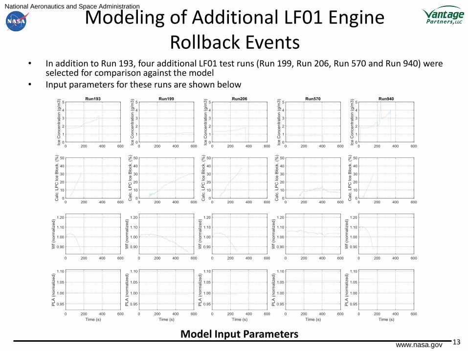
Modeling of Additional LF01 Engine Rollback Events
• In addition to Run 193, four additional LF01 test runs (Run 199, Run 206, Run 570 and Run 940) were selected for comparison against the model
• Input parameters for these runs are shown below
Model Input Parameters

14
National Aeronautics and Space Administration
www.nasa.gov
Modeling of Additional LF01 Engine Rollback Events (cont.)
Model Output Parameters
15
National Aeronautics and Space Administration
www.nasa.gov
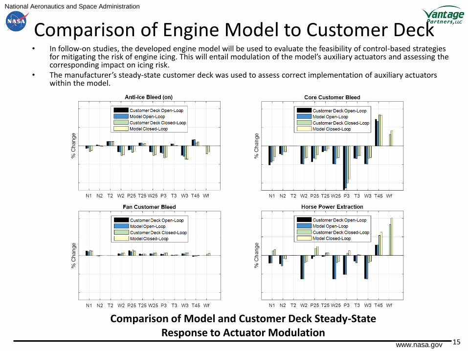
Comparison of Engine Model to Customer Deck• In follow-on studies, the developed engine model will be used to evaluate the feasibility of control-based strategies
for mitigating the risk of engine icing. This will entail modulation of the model’s auxiliary actuators and assessing the corresponding impact on icing risk.
• The manufacturer’s steady-state customer deck was used to assess correct implementation of auxiliary actuators within the model.
Comparison of Model and Customer Deck Steady-State Response to Actuator Modulation

16
National Aeronautics and Space Administration
www.nasa.gov
Summary
• A dynamic model of the ALF502-5R turbofan engine has been developed and evaluated
• Model was shown to emulate engine system-level behavior during ice crystal icing test cell evaluations as well as the steady-state outputs produced by the manufacturer’s customer deck
• Key features of the model include– Closed-loop controller allowing the simulation of engine transients– Heat extraction effects reflecting the heat loss the engine experiences as
ingested ice crystals melt and vaporize in its compression system– Flow blockage effects reflecting the buildup of ice in the engine’s low
pressure compressor– Auxiliary actuators enabling the modulation of engine performance
• Potential follow-on work– The model can be used in follow-on studies to develop and evaluate
potential icing risk detection and control-based mitigation strategies

17
National Aeronautics and Space Administration
www.nasa.gov
Acknowledgments
• This work was conducted under the NASA Advanced Air Vehicles Program, Advanced Air Transportation Technologies Project. The authors graciously acknowledge Honeywell Engines and the Ice Crystal Consortium for their support of the engine testing that enabled this work.