A Comparative Study of Hydrogen-Induced Cracking...
8
Research Article A Comparative Study of Hydrogen-Induced Cracking Resistances of API 5L B and X52MS Carbon Steels Rodrigo Monzon Figueredo, Mariana Cristina de Oliveira, Leandro Jesus de Paula, Heloisa Andréa Acciari , and Eduardo Norberto Codaro School of Engineering, S˜ ao Paulo State University (UNESP), Guaratinguet´ a, SP, Brazil Correspondence should be addressed to Heloisa Andr´ ea Acciari; [email protected] Received 8 January 2018; Revised 8 April 2018; Accepted 10 April 2018; Published 13 May 2018 Academic Editor: Ramana M. Pidaparti Copyright © 2018 Rodrigo Monzon Figueredo et al. is is an open access article distributed under the Creative Commons Attribution License, which permits unrestricted use, distribution, and reproduction in any medium, provided the original work is properly cited. Susceptibility to hydrogen-induced cracking of API 5L B and X52MS low-carbon steels in NACE 177-A, 177-B, and 284-B solutions has been investigated by the present work. A metallographic analysis of these steels was performed before and aſter NACE TM0284 standard testing. Corrosion products were characterized by scanning electron microscopy and X-ray dispersive energy spectrometry, which were subsequently identified by X-ray diffraction. us it was found that pH directly affects the solubility of corrosion products and hydrogen permeation. Both steels showed generalized corrosion in solution 177-A, and a discontinuous film was formed on their surfaces in solution 177-B; however, only the API 5L B steel failed the HIC test and exhibited greater crack length ratio in solution 177-A. In solution 284-B whose pH is higher, the steels exhibited thick mackinawite films with no internal cracking. 1. Introduction In the latest decades, the world has been experiencing a continuous growth in the demand for oil and its derivatives. Despite all efforts to diversify the energy matrix world, current projections still reveal a considerable increase in the demand for oil and natural gas. is growing demand and the fact that many countries aim to obtain strategic autonomy from their energy matrix have led to increased exploitation complex oil and gas sources [1]. ese sources present greater geological (depth, pressure, and temperature) and geographical (remote regions and marine currents) difficulties, as well as products with higher concentrations of hydrogen sulfide, commonly known as sour gas. e corrosion of steel pipelines by hydrogen sulfide has been a recurrent problem for oil and natural gas exploitation and production industry, which has aroused special attention aſter the discovery of the Brazilian pre-salt in 2006. Hydrogen sulfide together with other characteristics of the medium, such as temperature and pH condition, can cause general corrosion, localized corrosion, embrittlement, and cracking of pipelines; moreover, there is a large history of such occurrences in valves and welded joints. Pipeline rupture or its parts also have great environmental and economic impacts due to leaks and explosions, which lead to a halt in production [2–5]. Although corrosion consequences are well known, causes and mechanisms by which each phenomenon occurs are still not well understood. General corrosion is attributed to the preferential dissolution of the ferritic phase and it oſten manifests by a cementite scale (Fe 3 C) formation. Localized corrosion arises from the galvanic couples between the ferritic phase and nonmetallic (e.g., MnS) or intermetallic (e.g., Fe 3 C) inclusions and it manifests as pitting [6, 7]. e steps of a possible mechanism of hydrogen-induced cracking (HIC) can be, first, interstitial diffusion of hydrogen atoms under the steel surface. It occurs at a rate that depends on the packaging of the iron unit cell, that is, greater diffusibil- ity in the ferrite phase (bcc) than in the more compact austen- ite phase (fcc). en, hydrogen concentration at trapping sites: punctiform defects (gaps), linear defects (dislocations), two-dimensional defects (grain contours, mainly triple grain junction), and discontinuities (pores and contours of inter- metallic particles such as Fe 3 C, nonmetallic inclusions such as MnS, and impurities as oxides). e next step can be Hindawi International Journal of Corrosion Volume 2018, Article ID 1604507, 7 pages https://doi.org/10.1155/2018/1604507
Transcript of A Comparative Study of Hydrogen-Induced Cracking...
Research ArticleA Comparative Study of Hydrogen-Induced Cracking Resistancesof API 5L B and X52MS Carbon Steels
Rodrigo Monzon Figueredo, Mariana Cristina de Oliveira, Leandro Jesus de Paula,Heloisa Andréa Acciari , and Eduardo Norberto Codaro
School of Engineering, Sao Paulo State University (UNESP), Guaratingueta, SP, Brazil
Correspondence should be addressed to Heloisa Andrea Acciari; [email protected]
Received 8 January 2018; Revised 8 April 2018; Accepted 10 April 2018; Published 13 May 2018
Academic Editor: Ramana M. Pidaparti
Copyright © 2018 Rodrigo Monzon Figueredo et al. This is an open access article distributed under the Creative CommonsAttribution License, which permits unrestricted use, distribution, and reproduction in any medium, provided the original work isproperly cited.
Susceptibility to hydrogen-induced cracking of API 5L B and X52MS low-carbon steels in NACE 177-A, 177-B, and 284-B solutionshas been investigated by the present work. A metallographic analysis of these steels was performed before and after NACETM0284 standard testing. Corrosion products were characterized by scanning electron microscopy and X-ray dispersive energyspectrometry, which were subsequently identified by X-ray diffraction. Thus it was found that pH directly affects the solubility ofcorrosion products and hydrogen permeation. Both steels showed generalized corrosion in solution 177-A, and a discontinuousfilm was formed on their surfaces in solution 177-B; however, only the API 5L B steel failed the HIC test and exhibited greater cracklength ratio in solution 177-A. In solution 284-B whose pH is higher, the steels exhibited thick mackinawite films with no internalcracking.
1. Introduction
In the latest decades, the world has been experiencing acontinuous growth in the demand for oil and its derivatives.Despite all efforts to diversify the energy matrix world,current projections still reveal a considerable increase inthe demand for oil and natural gas. This growing demandand the fact that many countries aim to obtain strategicautonomy from their energy matrix have led to increasedexploitation complex oil and gas sources [1]. These sourcespresent greater geological (depth, pressure, and temperature)and geographical (remote regions and marine currents)difficulties, as well as products with higher concentrationsof hydrogen sulfide, commonly known as sour gas. Thecorrosion of steel pipelines by hydrogen sulfide has been arecurrent problem for oil and natural gas exploitation andproduction industry, which has aroused special attentionafter the discovery of the Brazilian pre-salt in 2006. Hydrogensulfide together with other characteristics of the medium,such as temperature and pH condition, can cause generalcorrosion, localized corrosion, embrittlement, and crackingof pipelines; moreover, there is a large history of such
occurrences in valves and welded joints. Pipeline ruptureor its parts also have great environmental and economicimpacts due to leaks and explosions, which lead to a halt inproduction [2–5]. Although corrosion consequences are wellknown, causes and mechanisms by which each phenomenonoccurs are still not well understood. General corrosion isattributed to the preferential dissolution of the ferritic phaseand it often manifests by a cementite scale (Fe3C) formation.Localized corrosion arises from the galvanic couples betweenthe ferritic phase and nonmetallic (e.g., MnS) or intermetallic(e.g., Fe3C) inclusions and it manifests as pitting [6, 7].
The steps of a possible mechanism of hydrogen-inducedcracking (HIC) can be, first, interstitial diffusion of hydrogenatoms under the steel surface. It occurs at a rate that dependson the packaging of the ironunit cell, that is, greater diffusibil-ity in the ferrite phase (bcc) than in themore compact austen-ite phase (fcc). Then, hydrogen concentration at trappingsites: punctiform defects (gaps), linear defects (dislocations),two-dimensional defects (grain contours, mainly triple grainjunction), and discontinuities (pores and contours of inter-metallic particles such as Fe3C, nonmetallic inclusions suchas MnS, and impurities as oxides). The next step can be
HindawiInternational Journal of CorrosionVolume 2018, Article ID 1604507, 7 pageshttps://doi.org/10.1155/2018/1604507
2 International Journal of Corrosion
Table 1: Chemical composition of API 5L X52MS and API 5L B steels (wt.%).
Steel C Si Mn P S V Nb TiX52MS 0.03 0.21 1.18 0.01 0.000 0.004 0.03 0.01B 0.10 0.32 0.86 0.02 0.002 0.002 0.02 0.02
Table 2: Mechanical properties of steels.
Steel FL (MPa) RL (MPa) EL (%) Hardness (HV10) Tenacity at −20∘C (J)X52MS 440 485 44 173 403B 373 458 41 170 205
hydrogen atoms interaction with other atoms or cationsin these sites of the iron crystalline network and hencedecrease of the reticular energy (decohesion). After that,the recombination of hydrogen atoms and pressurization ofthese sites causes internal stress. Finally, this pressurization ismanifestedmainly in the formof blisters near the steel surfaceand internal cracks aligned in the direction ofmaterial rolling(HIC) [2, 8].
Since the chemical compositions of petroleum, naturalgas, and producedwater varywidely, and laboratory tests can-not reproduce the internal conditions of oil and gas pipelines,standard tests have been developed for qualifying of carbonsteels. Corrosion standard tests of carbon steels to be usedin oil and gas production establish specific conditions forpH, temperature, H2S partial pressure, and time of exposure[8, 9]. It is important to note that the test solutions describedby these standards do not simulate a sour environment butrather provide a reproducible test environment capable ofevaluating the susceptibility to cracking of different steels ina relatively short period of time. In the pipe manufacturingindustry, it is common to classify steels according to theircorrosion resistance in one of these test solutions. However,there is always uncertainty in trying to extrapolate resultsbased on production and test history, that is, how a productwould behave in a low pH medium when it was originallydesigned and qualified for being used in a high pH medium.
Thus, the present work aims to study the resistance tohydrogen-induced cracking of API 5L B and X52MS steels in177-A, 177-B, and 284-BNACE solutions.The corrosion prod-ucts were characterized by electron microscopy (SEM) andX-ray dispersive energy spectrometry (EDS) and identifiedby X-ray diffraction (XRD).
2. Materials and Methods
API 5L X52MS and API 5L B carbon steels pipes arecommonly manufactured in Brazil. The first one is producedto resist harsh sour conditions, whereas the last one isused in sweet or slightly acidic environments. The pipeswere manufactured according to standard [10] through thecold forming process by three-stage pressing (edge pressing,U-shaped pressing, and O-shaped pressing), followed bylongitudinal submerged arc welding, and expansion in orderto calibrate the final geometry of pipes.
Table 3: Chemical composition of solutions 177-A and 177-B.
Compounds Concentration (wt.%)177-A 177-B
NaCl 5.0 5.0HCH3COO 0.50 2.5NaCH3COO - 0.41
Chemical composition of these steels (Table 1) was deter-mined by optical emission spectrometry with aThermo ARL3460 spectrometer and the ARLWinOE software.
TheAPI 5L X52MS steel is quite able to support operationin H2S-containing environments, being qualified in themanufacturing plant through tests in solution 177-A (Table 2).It should have maxima CLR (crack length ratio), CTR (crackthickness ratio), and CSR (crack sensitivity ratio) at 15%,5.0%, and 2.0%, respectively, to be considered qualified [3].The API 5L B steel used herein has not been heat-treated,thus not being appropriate for all the sour environments.It was chosen so as to compare hydrogen-induced crackingresistances of the two steels. Samples of 100× 20× 10mmweretaken from the pipes by plasma cutting at approximately 90degrees from the longitudinal weld.
To evaluate their resistance to HIC, two flasks were usedfor each test, one containing 10 L of test solution (Tables 3 and4) and the other one with 10 100 × 20 × 10mm samples, beingfive of each steel (Figure 1). These samples were placed ona plastic grid at 25mm from the bottom of the vessel beingat least 15mm apart from each other. A screwed cap anda rubber gasket ring closed the vessels. An inlet valve witha delivery tube was used for gas injection and solution testtransferring. An outlet valve was used for internal pressurerelief and gas washing. The vessels and gas-washing bottlewere placed inside a laboratory fume hood equipped witha hydrogen sulfide detector. The test solution was purgedof air with N2(g) 99.999% for 1 h at 100mL/min per liter oftest solution prior to transferring the test solution into thetest vessel. Then, 8.0 L of test solutions was transferred bypositive pressure of N2(g). The test vessel containing the testsolution was purged with N2(g) for 1 h at 100mL/min perliter of test solution and then saturated with H2S(g) 99.9%at the same flow rate so as to ensure that the test solution

International Journal of Corrosion 3
Table 4: Composition of solution 284-B adjusted to pH 8.2 with NaOH.
Compounds (g L−1)
NaCl Na2SO4 MgCl2⋅6H2O CaCl2 SrCl2⋅6H2O24.53 4.09 11.11 1.16 0.042KCl NaHCO3 KBr H3BO3 NaF0.695 0.201 0.101 0.027 0.003
�ermometer
For the gas scrubber
HIC TestContainer
Samples forHIC tests
Samplingpoint
cylinderH2S
cylinderN2 Solution
preparationcontainer
T
Figure 1: Hydrogen-induced cracking test apparatus.
remains saturated with H2S(g) for 96 hours of testing. Thetests were performed at a temperature of 24∘C±3∘C. At every24 h, an aliquot of the test solution was collected in order tomeasure pH and H2S(g) concentration, with the former beingby iodometric titration. According to standard test method[8], the standard pH range for 177-A solution was 2.6 to 2.8 atthe beginning of the test and<4.0 at the end of the test; for 177-B, the range was set at 3.4 to 3.6 at the beginning and <4.0 atthe end; for 284-B the range is from 8.1 to 8.3 at the beginningand 4.8 to 5.4 at the end of the test. In this work, pHvalues andH2S(g) concentrations (≥2,300 ppm) were in good agreementwith the aforementioned NACE standard. After 96 h, thedesulfurization process was initiated by bubbling with N2(g).The test vessel was drained and opened, and the sampleswere carefully washed in deionized water, dried under streamof N2(g), and introduced into a desiccator containing silica,which was connected to a vacuum pump.
Scanning electron microscopy (SEM) analyses were car-ried out on surfaces and cross sections of samples witha Jeol 6350 scanning electron microscope. Local chemicalcomposition was determined by X-ray dispersive energyspectrometry (EDS) using aThermoC10015 probe controlledby the Noran System SIX software. X-ray diffraction (XRD)analyses were carried out on corroded surfaces using theBruker D8 Advance Eco diffractometer equipped with theDIFFRAC.EVA software. In order to study the temporalevolution of corrosion products in a longer immersion time,a further experiment was performed, thus exposing a newsample to solution 284-B for 35 days at room temperature.In this case, by following the preparation and transfer stagesof solution 284-B, the test vessel containing the test solutionwas purged with N2(g) for 1 h at 100mL/min per liter of 284-B
and then saturated with H2S(g) 99.9% for 1 h at the same flowrate (i.e., nonstationary conditions).
3. Results and Discussion
API 5L X52MS carbon steel shows the ferritic-bainitic matrixwith high grain refinement and random inclusion distri-bution (Figure 2(a)). On the other hand, API 5L B carbonsteel shows a ferrite-pearlite microstructure and presence ofbanding (Figure 2(b)).
Cross-sectional analyses of the API 5L X52MS sampleshave not revealed the occurrence of cracks in any of thetest solutions (Table 5), which is probably due to a lowconcentration of alloying elements with subsequent lowsegregation and banding of the microstructure. The API 5LB samples obtained high values of CLR and CTR for solution177-A, that is, 40%higher than those observed in solution 177-B on average, and no cracks were found in solution 284-B, asshown in Table 6.
These results are directly associated with hydrogen per-meation throughout steel. The concentration of hydrogenions decreases as the pH and deposited film thicknessincrease, which can hinder hydrogen diffusion and penetra-tion into steel [6, 11]. Cracks can be observed in the crosssections of samples exposed to solutions 177-A and 177-B,respectively, in Figures 3 and 4.
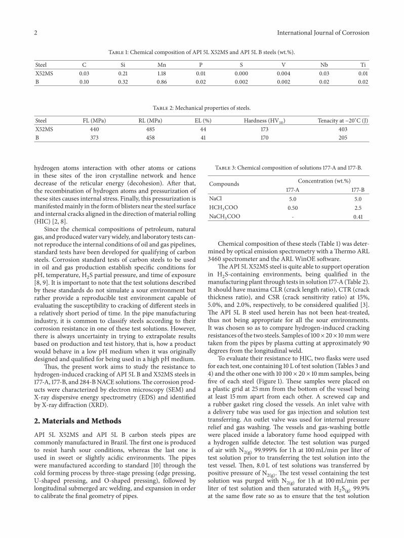
SEM in Figure 5(a) shows cracks towards the samedirection, that is, parallel to the sample surface. Figure 5(b)shows details of crack nucleation from the inclusion of MnSinto steel B. Figure 5(c) shows the results of the EDS analysisof a region indicated by an arrow in Figure 5(b). Crackswere mainly developed during the elongated inclusions ofMnS, as observed in Figure 5(b). The composition of the

4 International Journal of Corrosion
Table 5: HIC test results for the API 5L X52MS steel.
177-A 177-B 284-BCP CLR CTR CSR CP CLR CTR CSR CP CLR CTR CSR1 0 0 0 7 0 0 0 12 0 0 02 0 0 0 8 0 0 0 13 0 0 03 0 0 0 9 0 0 0 14 0 0 04 0 0 0 10 0 0 0 15 0 0 05 0 0 0 11 0 0 0 16 0 0 0Med 0 0 0 Med 0 0 0 Med 0 0 0
Table 6: HIC test results for the API 5L B steel.
177-A 177-B 284-BCP CLR CTR CSR CP CLR CTR CSR CP CLR CTR CSR16 26% 3% 1% 21 29% 3% 1% 26 0 0 017 35% 4% 1% 22 27% 3% 1% 27 0 0 018 48% 4% 2% 23 32% 4% 1% 28 0 0 019 35% 5% 2% 24 16% 2% 0% 29 0 0 020 46% 7% 3% 25 32% 1% 0% 30 0 0 0Med 38% 5% 2% Med 27% 2% 1% Med 0 0 0
50 𝜇m
(a)
50 𝜇m
(b)
Figure 2: Microstructure of the central region of the API 5L steel plates: (a) X52MS and (b) B (metallographic etchant: 3.0% nital solution).
Figure 3: Stepwise cracks in the cross section of theAPI 5L B sampleexposed to solution 177-A.
Figure 4: Stepwise cracks in the cross section of theAPI 5L B sampleexposed to solution 177-B.
inclusion at the crack tip in Figure 5(b) is presented in theEDS spectrum of Figure 5(c), in which S and Mn peaks canbe clearly observed.
It is well known that the cracking in H2S environments isassociated with the presence of nonmetallic inclusions, suchas MnS and Ti or V carbonitrides, and a banded structure.The heterogeneous distribution of these inclusions also favorscracking due to the higher concentration of hydrogen trapsin some regions. Segregations associated with high levels of Pand S in steel contribute to the accumulation of hydrogen inthe material [7, 12–16].
The surface analysis has revealed that, for the lowest pHsolution (177-A solution), there was no film formation on thesample, as shown in Figures 6(a) and 6(b) and confirmedby the EDS analysis of region 3, Figure 6(c), in which onlypeaks associated with Fe and Mn are observed. The carbonsteel exhibited generalized corrosion at low pH, probably dueto high solubility of iron sulfide and preferential attack offerritic phase [6, 7]. In solution 177-B, a discontinuous layerwith some degree of crystallinity was observed on a region ofthe surface shown in Figures 6(d) and 6(e). The EDS analysis
International Journal of Corrosion 5
(a) (b)
1500
1000
500
0
0 1 2 3 4 5 6 7 8 9 10
(keV)
Full scale counts: 1154
(c)
Figure 5: Micrographs showing details of crack nucleation from the inclusion of MnS into the API 5L B steel: (a) 400x and (b) 1500x; (c) EDSanalysis of the region indicated by an arrow at (b) micrograph.
indicates sulfur-rich sulfides (nonstoichiometric FeS) in thecrystalline region depicted in Figure 6(f). Similar surfacecharacteristics were reported in another work on low-carbonsteels in 5.0% NaCl solution saturated with H2S and pH4.2 [17]. It was not possible to identify any iron sulfidesby the XRD analysis due to a small amount of corrosionproducts.
In solution 284-B at a higher pH, there was a considerableamount of insoluble sulfides resulting from the saturationstep with H2S, as shown in Figures 6(g) and 6(h) andconfirmed by the EDS of region 3 in Figure 6(i). This thickfilm probably provides greater resistance to diffusion of ionicspecies, thus hindering the corrosion process in compari-son with discontinuous films formed at a lower pH. TheXRD surface analysis has only identified corrosion productsformed in solution 284-B. The diffractogram of corrosionproducts obtained after 96 h of exposure (Figure 7) showspeaks at approximately 18∘, 30∘, 35∘, 38∘, 50∘, and 54∘ whichare the same as those of mackinawite (M), that is, a tetragonalcrystalline form of iron sulfide [18]. A similar diffractogramhas been reported by Zheng et al. [19] and Zhou et al.[20].
Several iron sulfide polymorphs have been identifiedwithin oil and gas pipelines. The most cited monosulfidesare tetragonal mackinawite, hexagonal troilite, monoclinicpyrrhotite, and hexagonal pyrrhotite, all which are relativelystable in oxygen-free acid media [21–23]. Corrosion tests atroom temperature using artificial sea water or any other salt
solutions saturated with hydrogen sulfide often lead to oneor two types of iron sulfides, that is, mackinawite (kineticallyfavored product) and pyrrhotite (thermodynamically favoredproduct).
In order to study the temporal evolution of corrosionproducts, another corrosion test was performed in a longerimmersion time in solution 284-B. The diffractogram ofcorrosion products obtained after 35 days of exposure onlyshowed mackinawite peaks (Figure 8). When comparedto Figure 7, mackinawite peaks increase and iron peaksdecrease, which is probably due to surface coverage and thesulfide layer thickening during immersion time.
4. Conclusion
Cracking resistance seems to be directly associated with thesteel microstructure and medium acidity. API 5L B andX52MS steels showed generalized corrosion in solution 177-A. Both steels formed a discontinuous layer when exposedto solution 177-B. Only the API 5L B steel failed the HICtest and exhibited a larger crack length ratio in solution177-A. The SEM-EDS analysis reveals that cracks were ini-tiated in the MnS inclusions. In solution 284-B, a thickmackinawite film was formed on both steels, and no crackin their microstructures was observed. When the API 5LX52MS steel was exposed to a longer immersion time, mack-inawite was the only corrosion product obtained from theprocess.

6 International Journal of Corrosion
6553522101 6553516899 21553 61243
1 2 3 4 5 6 7
(keV)1 2 3 4 5 6 7
(keV)1 2 3 4 5 6 7
(keV)
(a)
(b)
(c)
(d)
(e)
(f)
(g)
(h)
(i)
Figure 6: SEM and EDS analyses of corrosion products in the API 5L X52MS steel. This steel exposed to 177-A solution: (a) 200x, (b) 3000x,and (c) EDS. This one exposed to 177-B solution: (d) 200x, (e) 3000x, and (f) EDS. This one exposed to 284-B solution: (g) 200x, (h) 3000x,and (i) EDS.
10 20 30 40 50 60 70 80
2 �eta (∘)
M
MM
M MMM
M
Fe
Fe
Figure 7: XRD analysis of the API 5L X52MS steel exposed tosolution 284-B for 96 h (M: mackinawite).
Data Availability
The data used to support the findings of this study areavailable from the corresponding author upon request.
MM
M
M
M
M
M
M
M
FeFe
10 20 30 40 50 60 70 80
2 �eta (∘)
Figure 8: XRD analysis of the API 5L X52MS steel exposed tosolution 284-B for 35 days (M: mackinawite).
Conflicts of Interest
The authors declare that they have no conflicts of interest.

International Journal of Corrosion 7
Acknowledgments
Theauthorswould like to thankPROEX/UNESP,CAPES, andFAPESP (Process 2017/11361-5) for the financial support.
References
[1] IEA, Resources to Reserves 2013 - Oil, Gas and Coal Technologiesfor the Energy Markets of the Future, International EnergyAgency, Paris, France.
[2] M.A.Mohtadi-Bonab, J. A. Szpunar, R. Basu, andM. Eskandari,“The mechanism of failure by hydrogen induced cracking in anacidic environment for API 5L X70 pipeline steel,” InternationalJournal of Hydrogen Energy, vol. 40, no. 2, pp. 1096–1107, 2015.
[3] ISO, “Petroleum and Natural Gas Industries - Materials for usein H2S-Containing Environments in Oil and Gas Production -Part 1,” Tech. Rep. ISO 15156-1, International Organization forStandardization, Switzerland, 2009.
[4] D. Talbot, Corrosion Science and Technology, CRC Press, NewYork, NY, USA, 2007.
[5] B. P. Tissot and D. H. Welte, Petroleum Formation and Occur-rence, Springer, Berlin, Germany, 2nd edition, 1984.
[6] C. Zhou, S. Zheng, C. Chen, and G. Lu, “The effect of the partialpressure of H2S on the permeation of hydrogen in low carbonpipeline steel,” Corrosion Science, vol. 67, pp. 184–192, 2013.
[7] J. Sojka, M. Jerome, M. Sozanska, P. Vanova, L. Rytırova, andP. Jonsta, “Role of microstructure and testing conditions insulphide stress cracking of X52 and X60 API steels,” MaterialsScience and Engineering: A Structural Materials: Properties,Microstructure and Processing, vol. 480, no. 1-2, pp. 237–243,2008.
[8] NACE International, “Evaluation of Pipeline and pressure vesselsteel for resistance to hydrogen-induced crack,” Tech. Rep.ANSI/NACE TM0284, NACE International, Houston, Tex,USA, 2017.
[9] NACE International, “Standard test method laboratory testingof metals for resistance to sulfide stress cracking and stress cor-rosion cracking in H2S environments,” Tech. Rep. ANSI/NACETM0177, NACE International, Houston, Tex, USA, 2016.
[10] API 5L, “Specification for Line Pipe,” Tech. Rep., API PublishingServices, Washington, Wash, USA, 2012.
[11] K. Kobayashi, T. Omura, M. Okatsu, T. Hara, and N. Ishikawa,“Proposal of HIC test solution with buffer capacity in NACETM0284,” in Proceedings of the NACE - International CorrosionConference Series, Orlando, Fla, USA, 2013.
[12] F. Huang, J. Liu, Z. Deng, J. Cheng, Z. Lu, and X. Li, “Effect ofmicrostructure and inclusions on hydrogen induced crackingsusceptibility and hydrogen trapping efficiency of X120 pipelinesteel,”Materials Science and Engineering: A StructuralMaterials:Properties, Microstructure and Processing, vol. 527, no. 26, pp.6997–7001, 2010.
[13] L. Gan, F. Huang, X. Zhao, J. Liu, and Y. F. Cheng, “Hydrogentrapping and hydrogen induced cracking of welded X100pipeline steel in H2S environments,” International Journal ofHydrogen Energy, vol. 43, no. 4, pp. 2293–2306, 2018.
[14] M. Elboujdaini and R. W. Revie, “Metallurgical factors in stresscorrosion cracking (SCC) and hydrogen-induced cracking(HIC),” Journal of Solid State Electrochemistry, vol. 13, no. 7, pp.1091–1099, 2009.
[15] A. C. Palmer and R. A. King, Subsea Pipeline Engineering, Pen-nWell, Tulsa, Okla, USA, 2008, Subsea Pipeline Engineering.
[16] M. A. Mohtadi-Bonab and M. Eskandari, “A focus on differentfactors affecting hydrogen induced cracking in oil and naturalgas pipeline steel,” Engineering Failure Analysis, vol. 79, pp. 351–360, 2017.
[17] P. Bai, S. Zheng, and C. Chen, “Electrochemical characteristicsof the early corrosion stages of API X52 steel exposed to H2Senvironments,” Materials Chemistry and Physics, vol. 149, pp.295–301, 2015.
[18] J. Ning, Y. Zheng, B. Brown, D. Young, and S. Nesic, “Con-struction and verification of pourbaix diagrams for hydrogensulfide corrosion of mild steel,” in Proceedings of the NACE- International Corrosion Conference Series, Dallas, Tex, USA,2015.
[19] S. Zheng, C. Zhou, X. Chen, L. Zhang, J. Zheng, and Y. Zhao,“Dependence of the abnormal protective property on the cor-rosion product film formed on H2S-adjacent API-X52 pipelinesteel,” International Journal of Hydrogen Energy, vol. 39, no. 25,pp. 13919–13925, 2014.
[20] C. Zhou, X. Chen, Z. Wang, S. Zheng, X. Li, and L. Zhang,“Effects of environmental conditions on hydrogen permeationof X52 pipeline steel exposed to highH2S-containing solutions,”Corrosion Science, vol. 89, no. C, pp. 30–37, 2014.
[21] S. N. Smith, B. Brown, andW. Sun, “Paper 11081 of NACE Inter-national,” in Proceedings of the Paper 11081 of NACE Interna-tional, Houston, Tex, USA, 2011.
[22] B. Craig, “Corrosion product analysis - a roadmap to corrosionin oil and gas production,”Materials Performance, vol. 41, no. 8,pp. 56–58, 2002.
[23] S. N. Smith, “Corrosion product analysis in oil and gas pipe-lines,”Materials Performance, vol. 42, no. 8, pp. 44–47, 2003.

CorrosionInternational Journal of
Hindawiwww.hindawi.com Volume 2018
Advances in
Materials Science and EngineeringHindawiwww.hindawi.com Volume 2018
Hindawiwww.hindawi.com Volume 2018
Journal of
Chemistry
Analytical ChemistryInternational Journal of
Hindawiwww.hindawi.com Volume 2018
Scienti�caHindawiwww.hindawi.com Volume 2018
Polymer ScienceInternational Journal of
Hindawiwww.hindawi.com Volume 2018
Hindawiwww.hindawi.com Volume 2018
Advances in Condensed Matter Physics
Hindawiwww.hindawi.com Volume 2018
International Journal of
BiomaterialsHindawiwww.hindawi.com
Journal ofEngineeringVolume 2018
Applied ChemistryJournal of
Hindawiwww.hindawi.com Volume 2018
NanotechnologyHindawiwww.hindawi.com Volume 2018
Journal of
Hindawiwww.hindawi.com Volume 2018
High Energy PhysicsAdvances in
Hindawi Publishing Corporation http://www.hindawi.com Volume 2013Hindawiwww.hindawi.com
The Scientific World Journal
Volume 2018
TribologyAdvances in
Hindawiwww.hindawi.com Volume 2018
Hindawiwww.hindawi.com Volume 2018
ChemistryAdvances in
Hindawiwww.hindawi.com Volume 2018
Advances inPhysical Chemistry
Hindawiwww.hindawi.com Volume 2018
BioMed Research InternationalMaterials
Journal of
Hindawiwww.hindawi.com Volume 2018
Na
nom
ate
ria
ls
Hindawiwww.hindawi.com Volume 2018
Journal ofNanomaterials
Submit your manuscripts atwww.hindawi.com


![Stress-oriented hydrogen-induced cracking (SOHIC) in H2S ...ltsm.mead.upatras.gr/lab/public/image/conference...571 recommended practice [1] while the assessment of hydrogen damage](https://static.fdocuments.net/doc/165x107/6020d052a1d52c293713dc2b/stress-oriented-hydrogen-induced-cracking-sohic-in-h2s-ltsmmead-571-recommended.jpg)