973 Sf6 Manual
34
973-SF6 Dew Point Mirror and Purity Analyzer RH Systems 11500 Signal NE, Bldg 2 Albuquerque, NM 87122 505-856-5666 voice 505-856-5866 fax www.rhsystems.net [email protected] Operation and Maintenance Manual
-
Upload
ariel-martinez-n -
Category
Documents
-
view
244 -
download
0
Transcript of 973 Sf6 Manual

7/28/2019 973 Sf6 Manual
http://slidepdf.com/reader/full/973-sf6-manual 1/34
973-SF6 Dew Point Mirror and Purity Analyzer
RH Systems11500 Signal NE, Bldg 2 Albuquerque, NM 87122
505-856-5666 voice505-856-5866 fax
www.rhsystems.net [email protected]
Operation and
Maintenance Manual

7/28/2019 973 Sf6 Manual
http://slidepdf.com/reader/full/973-sf6-manual 2/34
Warranty
RH Systems (RHS) warrants the products it manufactures or distributes to be free of defects inmaterial and workmanship under normal use and service when operated within the specifieddesign limitations for a period of 12 months from date of initial shipment. Under this Warranty,RHS will, at its discretion, repair or replace any component that upon examination by RHS or its
duly authorized representatives proves to be defective during the warranty period provided thesystem is returned to the factory for inspection and repair shipping prepaid. Improper or unauthorized maintenance, storage, repair, or alteration of any kind by personnel other than RHSor its duly authorized representatives may void all warranties. Warranty may also be voided for misuse, neglect, accident, corrosion, and improper installation. This Warranty is exclusive and inlieu of any and all other warranties of merchantability, fitness for a particular purpose, or anyother warranty, expressed or implied, and all other liabilities and obligations on the part of RHS.RHS will not be liable for any other claims or damages, either direct, indirect, or consequentialarising out of the use of its products.

7/28/2019 973 Sf6 Manual
http://slidepdf.com/reader/full/973-sf6-manual 3/34
i
Table of Contents
973-SF6 Dew Point Mirror and Purity Analyzer ........................................................................... i Table of Contents ........................................................................................................................... i Welcome......................................................................................................................................... 1 How to Use This Manual ............................................................................................................... 1
For More Information ................................................................................................................... 1 OPERATION ........................................................................................................3 Getting Started............................................................................................................................... 3
Turning the 973 On and Off ......................................................................................................... 3 What You See.............................................................................................................................. 3 The Touch Screen ....................................................................................................................... 5 The Measuring Head Assembly................................................................................................. 10 Humidity Measurement.............................................................................................................. 10
System Configuration ................................................................................................................. 13 Menu Options............................................................................................................................. 13 Display Parameters.................................................................................................................... 14 Graphing Data............................................................................................................................ 16 Control Setup ............................................................................................................................. 14 Changing Color .......................................................................................................................... 18
Back Panel Connections............................................................................................................. 20 Power Plug................................................................................................................................. 20 Power Switch ............................................................................................................................. 20 RS-232....................................................................................................................................... 20 Gas Input and Output................................................................................................................. 20
Measurement Tips....................................................................................................................... 21 Measuring Range....................................................................................................................... 21 Cooling Requirements ............................................................................................................... 22
INSTALLATION..................................................................................................23 Facility Requirements................................................................................................................. 23
Environmental ............................................................................................................................ 23 Power......................................................................................................................................... 23
Preparation for Use ..................................................................................................................... 23 Benchtop Use............................................................................................................................. 23 Field Use.................................................................................................................................... 23
Preparation for Shipping or Transportation ............................................................................. 23 REMOTE COMMUNICATION ............................................................................25

7/28/2019 973 Sf6 Manual
http://slidepdf.com/reader/full/973-sf6-manual 4/34
ii
Introduction.................................................................................................................................. 25 Hardware Connection & Cabling................................................................................................ 25 Communications Settings.......................................................................................................... 26 Command Syntax ........................................................................................................................ 26
General Usage........................................................................................................................... 26 Termination Characters ............................................................................................................. 26 Leading and Trailing Spaces ..................................................................................................... 26 Case Sensitivity ......................................................................................................................... 27 Numeric Values.......................................................................................................................... 27
Command Reference................................................................................................................... 28 Commands Listed By Functional Group.................................................................................... 28
MAINTENANCE .................................................................................................29 Mirror Cleaning............................................................................................................................ 29 Exterior Cleaning......................................................................................................................... 30
Front Panel................................................................................................................................. 30

7/28/2019 973 Sf6 Manual
http://slidepdf.com/reader/full/973-sf6-manual 5/34
Welcome 1
WelcomeCongratulations! With the 973-SF6 Dew Point Mirror you will be able to perform precision dewpoint and frost point measurements as well as measurements of other parameters such as SF6Purity, PPMv and PPMw. The 973-SF6 was designed specifically for SF6 and the complexities
associated with measurement of water vapor in this gas. All measurements are controlledautomatically, which removes the subjective interpretation of results presented by non-automatedinstruments. At the completion of each measurement sequence, the pertinent data remains fixedon the display until you initiate the next measurement. The 973-SF6 utilizes a full color activematrix liquid crystal display with an integral touch panel. It has a high contrast ratio and a wideviewing angle for easy readability. Data is displayed in large easy to read fonts. Using the onscreen buttons and menus, you can easily configure each line of the display for a variety of parameters that may be viewed in either SI or non-SI units. In addition, all pressure parametersmay be viewed in either absolute or relative (also referred to as gauge or over-pressure) mode.
How to Use This Manual
If you have the time and inclination, you can read this manual from front to back. Since we realizeyour time is valuable and you may not wish to do that yet, we recommend the following approachto familiarize yourself with the 973-SF6 and start using it right away.
1. With the 973-SF6 at hand, go straight to the Getting Started section on page 3. From there,you can quickly learn to use the instrument to make a dew point measurement.
2. Next, read the System Configuration section beginning on page 13 to learn how to configurethe system to meet your preferences.
3. Finally, read the Back Panel Connections section beginning on page 20. That sectionidentifies all the electrical, fluid, and gas connections available on the back panel andexplains how and when to use them.
For More InformationFor a more thorough understanding of the 973-SF6 and other humidity measurement information,please read the remaining sections of this manual.
The Remote Communication section discusses the RS-232 interface both from a hardware andsoftware perspective. It gives details relating to cabling to connect the 973-SF6 to a computer,and gives the syntax and examples of each of the commands that the 973-SF6 recognizes.
The Maintenance section covers topics such as Mirror Cleaning and general maintenancerequired to keep your 973-SF6 performance at its best.
If the information you seek is not in one of the manual’s included sections, never hesitate tocontact us with your questions. Relevant phone, fax, and email contact information is on the front
page of this manual.

7/28/2019 973 Sf6 Manual
http://slidepdf.com/reader/full/973-sf6-manual 6/34

7/28/2019 973 Sf6 Manual
http://slidepdf.com/reader/full/973-sf6-manual 7/34
Getting Started 3
Data
Lines
FixedFunctionKeys
MenuKeys
Measurement Status Recover C linder Ca acit
Operation
Getting StartedThis section allows you to set up and start using the 973 right away. You’ll turn the system on andquickly familiarize yourself with the layout and features of the display and touch screen. Next,you’ll learn about the optical mirror assembly for later care and cleaning that may be required.Finally, you’ll use the 973 to measure the humidity in your gas-insulated equipment. Grab your 973 and let’s get started!
Turning the 973 On and Off The 973 needs a source of normal AC power. The 973 has been designed to work over a widepower range and will most likely operate at your local voltage and frequency. Look at the backpanel label for the power requirements of your specific system.
1. Using the supplied AC power cord, apply the proper voltage to the instrument by plugging thecord into the back of the instrument, then into an AC receptacle of the proper voltage.
2. The power switch is located on the back panel next to the power cord input. Turn it ON.
The display should become visible within a few seconds. If nothing seems to happen, check thepower source. There may also be some fuses located next to the power switch. You can removeand replace them with known good ones. Suspect fuses can be tested for continuity with anohmmeter.
What You SeeWhen power is applied to the 973, the display will activate within a few seconds. A typical displayconfiguration is depicted below. If you or someone else previously configured your system, it maylook slightly different. But don’t worry, we’ll show you how to set it up the way you like.
- - - -- - - -
- - - -6.561
Volume SF6%
Volume Ratioppmv
Dew Point°C (at P vessel)
Vessel Pressurebar abs.
Humidity
% V ol S F6
Pump Back
Internal
Cylinder
Start Pump

7/28/2019 973 Sf6 Manual
http://slidepdf.com/reader/full/973-sf6-manual 8/34
4 Getting Started
Data Lines
The first four lines of the display are for numeric or graphic representation of the measured data.We refer to those first four lines as data lines.
If numeric, a data line contains the value to the left, withthe parameter description and units to the right.
-9.65 Time Span 20.16.30-10.2 Time Span 00:30:00
-9.8
If graphic, a data line shows a simple graph of the dataover time.
The choice of which parameter is shown on which data line, as well as whether a data line isviewed as numeric or graphic, is easily selectable. You’ll see how to make these selectionsshortly.
Fixed Function Keys and Status Line
The bottom line of the display contains two fixedfunction keys. You’ll use these keys to start themeasurement process, and if necessary, to pump out
the internal recovery cylinder. The function of each of these keys never changes, and they are alwaysavailable for use.
Menu Keys
To the right side of the display is a column of menu keys. Each of these keys changesfunction as needed.
Notice that the bottom key in this column isdifferent from the rest. The bottom key is usedto cycle the upper keys through the various
menu options. The text on the bottom keychanges to indicate the currently selectedmenu option. The text of the upper keyschange based on the functions available in themenu.
Use thebottomkey tochangemenus
6.561
Vessel Pressure
bar abs.
Humidity
% V ol S F6
Pump Back
Internal
Cylinder
S tart Pump

7/28/2019 973 Sf6 Manual
http://slidepdf.com/reader/full/973-sf6-manual 9/34
Getting Started 5
The Touch ScreenThe 973 utilizes a touch screen for user interaction. To activate a menu option or toggle afunction on or off, simply touch the screen directly over the key or object desired.
Calibrate the Touch Screen
Before using the instrument for the first time, you may need to calibrate the touch screen to your finger positioning preference. Here’s how –
Press and hold the enter key on the numeric keypad for 3 or 4seconds. If you’ve done it correctly, you’ll hear two shortbeeps and a key in the upper right corner will turn yellow. If not, release the enter key and try again.
With the tip of your finger, press the center of the yellow keyin the upper right corner of the touch screen. It is labeled‘Touch This Key’. Once you touch it, the yellow color goesaway and another key turns yellow.
Now, touch the yellow key that’s in the lower left corner of thetouch screen. Once you touch it, the yellow color goes awayand you have successfully calibrated the touch screen.
Test your new touch screen calibration by pressing each of
the four blank menu keys on the right side of the touch screenseveral times. If they seem not to work well, just repeat thecalibration steps again from the beginning.
You may recalibrate the touch screen as often as needed, however, it is rarely required.

7/28/2019 973 Sf6 Manual
http://slidepdf.com/reader/full/973-sf6-manual 10/34
6 Getting Started
Navigating the Menus
The various menus of the right column of keys are navigated by using the key in the lower rightcorner of the touch screen. Each time you press the lower right key, a new menu appears on thekeys directly above it. The menu is circular, meaning that once you go past the last menu, the firstone appears again and the process starts over. You can use the +/- key on the keypad to move
backward through the menus. Use the enter key to clear the menu.
Selecting the Measurement Options
The measuring options may be selected to allow for humidity measurement, %Vol SF6 puritymeasurement, or both. In addition, the system can be set for automatic pump back of the samplegas, or it can hold the gas for later pumping into an alternate tank or cylinder.
Press the lower right menu key once to select the Control Setupmenu. ‘Control Setup’ appears on the key while the keys abovechange to available menu options. Notice that the top keyindicates ‘Measuring Options’.
Press the Measuring Options menu key at the top right corner of the screen. The Measurement Control Setup window appears.
Several buttons appear in the window to allow selection of Humidity Measurement, %Vol SF6 Measurement, and PumpBack after Measurement. A small green box in the left of anoption button indicates that the option is currently enabled. If thebox is not green, then the option is currently disabled. To enableor disable an option, just press the button. Each time you pressthe button, the green square toggles on or off.
For purposes of this example, select only Humidity
Measurement, and disable the others.
Now press the Ok button or the enter key.
- - - -- - - -
- - - -1.013
Volume SF6%
Volume Ratioppmv
Frost Point°C (at P vessel)
Vessel Pressurebarabs.
Internal
Cylinder
Humidity
% Vol SF6
Pump Back
Start Pump
- - - -- - - -- - - -1.013
Volume SF6%
Volume Ratioppmv
Frost Point°C (at P vessel)
Vessel Pressurebarabs.
Internal
Cylinder
Humidity
% Vol SF6
Pump Back
Start Pump
Measuring
Options
Control
Setup
Ice Test
- - - -- - - -- - - -1.013
Volume SF6%
Volume Ratioppmv
Frost Point°C (at P vessel)
Vessel Pressurebarabs.
Internal
Cylinder
Humidity
% Vol SF6
Pump Back
Start Pump
Measuring
Options
Control
Setup
Ice TestMeasurement Control Setup
Descript ion:
Humidity Measurement
%Vol SF6 Measurement
Pump Back After Measurement
Ok Cancel
Measurement Control Setup
Description:
Humidity Measurement
%Vol SF6 Measurement
Pump Back After Measurement
Ok Cancel
7/28/2019 973 Sf6 Manual
http://slidepdf.com/reader/full/973-sf6-manual 11/34
Getting Started 7
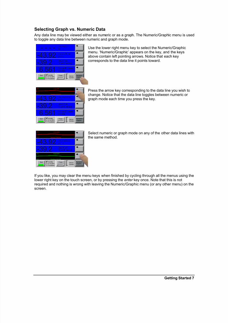
Selecting Graph vs. Numeric Data
Any data line may be viewed either as numeric or as a graph. The Numeric/Graphic menu is usedto toggle any data line between numeric and graph mode.
Use the lower right menu key to select the Numeric/Graphicmenu. ‘Numeric/Graphic’ appears on the key, and the keys
above contain left pointing arrows. Notice that each keycorresponds to the data line it points toward.
Press the arrow key corresponding to the data line you wish tochange. Notice that the data line toggles between numeric or graph mode each time you press the key.
Select numeric or graph mode on any of the other data lines withthe same method.
If you like, you may clear the menu keys when finished by cycling through all the menus using thelower right key on the touch screen, or by pressing the enter key once. Note that this is notrequired and nothing is wrong with leaving the Numeric/Graphic menu (or any other menu) on thescreen.
- - - -
-43.92-39.26.561
Volume SF6%
Volume Ratio
ppmv
Dew Point°C (at P vessel)
Vessel Pressurebar abs.
Humidity
% Vol SF6
PumpBack
Internal
Cylinder
Start PumpXX
Numeric/Graphic
- - - --43.92-39.2
6.561
Volume SF6%
Volume Ratioppmv
Dew Point°C (at P vessel)
Vessel Pressurebar abs.
Humidity
% Vol SF6
PumpBack
Internal
Cylinder
Start PumpXX
Numeric/Graphic
VolumeSF6
Time Span 00:0 3:00
%
111
109
- - - --43.92-39.26.561
Volume SF6%
Volume Ratioppmv
Dew Point°C (at P vessel)
Vessel Pressurebar abs.
Humidity
% Vol SF6
PumpBack
Internal
Cylinder
Start PumpXX
Numeric/Graphic
VolumeSF6
Time Span 00:0 3:00
%
111
109
VolumeSF6
Time Span 00:0 3:00
%
111
109

7/28/2019 973 Sf6 Manual
http://slidepdf.com/reader/full/973-sf6-manual 12/34
8 Getting Started
Selecting Parameters to Display
Selecting which parameters to display on the four data lines is easy. It is done with the Parameter menu.
Use the lower right menu key a couple of times to select the
Parameter menu. ‘Parameter’ appears on the key, and the keysabove get left pointing arrows. Notice that each key correspondsto the data line it points toward.
Press the arrow key corresponding to the data line you wish tochange. Notice that each time you press the arrow key, theparameter of the data line changes. The parameter selection is
circular, meaning that once you reach beyond the last availableparameter, the first one is again displayed and the cycle startsover. Change the parameters on any of the other four data lineswith the same method. For now select the parameters to matchthe picture to the left
If you like, you may clear the menu keys when finished bycycling through all the menus using the lower right key on thetouch screen, or by pressing the enter key once. Note that this isnot required and nothing is wrong with leaving the Parameter menu (or any other menu) on the screen.
- - - -- - - -
- - - -1.013
Volume SF6%
Volume Ratioppmv
Frost Point°C (at P vessel)
Vessel Pressurebarabs.
Internal
Cylinder
Humidity
% Vol SF6
Pump Back
Start Pump Parameter
- - - -- - - -- - - -
1.013
Volume SF6%
Volume Ratioppmv
Frost Point°C (at P vessel)
Vessel Pressure
barabs.
Internal
Cylinder
Humidity
% Vol SF6
Pump Back
Start Pump
- - - -- - - -- - - -1.013
Volume SF6%
Volume Ratioppmv
Frost Point°C (at P vessel)
Vessel Pressurebarabs.
Internal
Cylinder
Humidity
% Vol SF6
Pump Back
Start Pump Parameter

7/28/2019 973 Sf6 Manual
http://slidepdf.com/reader/full/973-sf6-manual 13/34
Getting Started 9
Selecting Units
The data may be viewed in any of the many available units.
Press the lower right menu key to select the Units menu. ‘Units’appears on the key, and the keys above contain current units
indications such as ‘Temp °C’. Notice that each of the keyscontain different types of units. Unlike the Parameters menu, thekeys do not correspond to the adjacent data lines, but rather todifferent units types.
To change temperature units, press the key labeled ‘Temp’.Notice that the corresponding units change each time the key ispressed. Also notice that any data line that is currently indicatingtemperature data also changes to reflect the new units.
Change other units (such as pressure, flow rate, etc.) with thesame method.
In addition to setting the pressure units, the mode may be set toeither absolute or relative mode. (Note: Relative mode is oftenreferred to as ‘gauge mode’ or ‘over-pressure’)
If you like, you may clear the Units keys when finished by cyclingthrough all the menus using the lower right key on the touchscreen, or by pressing the enter key once. Note that this is notrequired and nothing is wrong with leaving the Units menu (or any other menu) on the screen.
- - - -
- - - -- - - -1.013
Volume SF6%
Volume Ratio
ppmv
Frost Point°C (at P vessel)
Vessel Pressurebarabs.
Internal
Cylinder
Humidity
% Vol SF6
Pump Back
Start Pump Units
Temp
°C
Pressure
bar
Pressure
Mode
abs
Flow rate
l/m
Temp
°CTemp
°FTemp
K
Pressure
Mode
abs Pressure
Mode
rel
- - - -
- - - -- - - -1.013
Volume SF6%
Volume Ratioppmv
Frost Point°C (at P vessel)
Vessel Pressurebarabs.
Internal
Cylinder
Humidity
% Vol SF6
Pump Back
Start Pump

7/28/2019 973 Sf6 Manual
http://slidepdf.com/reader/full/973-sf6-manual 14/34
10 Getting Started
The Measuring Head AssemblyThe heart of the 973 Dew Point Mirror instrument is themeasuring head assembly. It is designed to be highlysensitive and accurate, yet rugged and easily accessible for periodic mirror cleaning. Although not required prior to initial
operation, you may wish to familiarize yourself with thelocation and accessibility of the mirror and the other opticalcomponents within this assembly.
For further discussion of the measuring head, and the mirror cleaning procedure, refer to Mirror Cleaning on page 29.
Humidity MeasurementWhen you power the 973 on, it begins in an idle state. In this state, it measures and displayspressure but does not yet provide any meaningful humidity related data. When properly
connected to gas-filled equipment, the measurement sequence may be initiated. At thecompletion of the measurement sequence the system will automatically stop and display theresults. The results remain fixed on the screen until you start another measurement or power thesystem off.
Making a measurement
Select the proper fitting to match that of your gas-insulatedequipment. The most common fittings, the Dilo DN8 and DN20,are usually supplied with the system and are stored in the lower compartment of the transport case along with the hose.
Connect the proper fitting to the end of the hose and tighten withwrenches.
At the opposite end of the hose, connect the Walther quickcoupling to the mating connector on the back panel of the 973,marked Sample Gas. Some older models have an extraconnector, marked Internal Cylinder Port, which is only used for evacuation of the internal storage tank and will not be used atthis time. On newer machines the function of this alternate fittinghas been integrated into the sample gas connector.
X
DN20
DN8
7/28/2019 973 Sf6 Manual
http://slidepdf.com/reader/full/973-sf6-manual 15/34
Getting Started 11
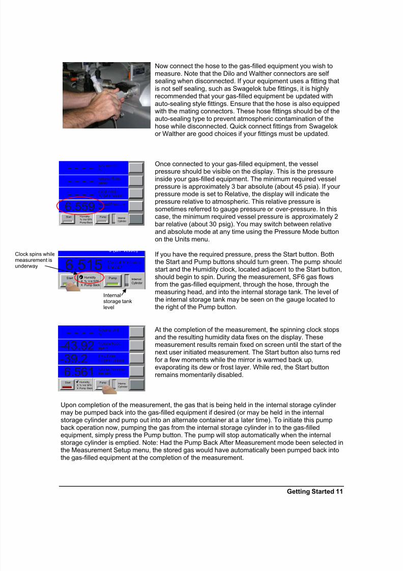
Now connect the hose to the gas-filled equipment you wish tomeasure. Note that the Dilo and Walther connectors are self sealing when disconnected. If your equipment uses a fitting thatis not self sealing, such as Swagelok tube fittings, it is highlyrecommended that your gas-filled equipment be updated withauto-sealing style fittings. Ensure that the hose is also equippedwith the mating connectors. These hose fittings should be of theauto-sealing type to prevent atmospheric contamination of thehose while disconnected. Quick connect fittings from Swagelokor Walther are good choices if your fittings must be updated.
Once connected to your gas-filled equipment, the vesselpressure should be visible on the display. This is the pressureinside your gas-filled equipment. The minimum required vesselpressure is approximately 3 bar absolute (about 45 psia). If your pressure mode is set to Relative, the display will indicate the
pressure relative to atmospheric. This relative pressure issometimes referred to gauge pressure or over-pressure. In thiscase, the minimum required vessel pressure is approximately 2bar relative (about 30 psig). You may switch between relativeand absolute mode at any time using the Pressure Mode buttonon the Units menu.
If you have the required pressure, press the Start button. Boththe Start and Pump buttons should turn green. The pump shouldstart and the Humidity clock, located adjacent to the Start button,should begin to spin. During the measurement, SF6 gas flowsfrom the gas-filled equipment, through the hose, through themeasuring head, and into the internal storage tank. The level of
the internal storage tank may be seen on the gauge located tothe right of the Pump button.
At the completion of the measurement, the spinning clock stopsand the resulting humidity data fixes on the display. Thesemeasurement results remain fixed on screen until the start of thenext user initiated measurement. The Start button also turns redfor a few moments while the mirror is warmed back up,evaporating its dew or frost layer. While red, the Start buttonremains momentarily disabled.
Upon completion of the measurement, the gas that is being held in the internal storage cylinder may be pumped back into the gas-filled equipment if desired (or may be held in the internalstorage cylinder and pump out into an alternate container at a later time). To initiate this pumpback operation now, pumping the gas from the internal storage cylinder in to the gas-filledequipment, simply press the Pump button. The pump will stop automatically when the internalstorage cylinder is emptied. Note: Had the Pump Back After Measurement mode been selected inthe Measurement Setup menu, the stored gas would have automatically been pumped back intothe gas-filled equipment at the completion of the measurement.
- - - -- - - -
- - - -6.559
Volume SF6%
Volume Ratioppmv
Frost Point°C (at P vessel)
Vessel Pressurebarabs.
Internal
Cylinder
Humidity
% Vol SF6
Pump Back
Start Pump
6.515
Vessel Pressurebar abs.
Humidity
% Vol SF6
Pump Back
Internal
Cylinder
Start PumpX
X
- - - --43.92-39.26.561
Volume SF6%
Volume Ratioppmv
Dew Point°C (at P vessel)
Vessel Pressurebar abs.
Humidity
% Vol SF6
Pump Back
Internal
Cylinder
Start PumpXX
Internal
storage tanklevel
Clock spins whilemeasurement isunderway

7/28/2019 973 Sf6 Manual
http://slidepdf.com/reader/full/973-sf6-manual 16/34
12 Getting Started
Now that you’ve completed the humidity measurement process, you may disconnect the fittingfrom the gas-filled equipment and move it to the next required measurement location.
Range Limitations
The 973 has a specific range of operation. The standard moisture measuring measuring range of the 973 is from -55°C frost point to +20°C dew point.

7/28/2019 973 Sf6 Manual
http://slidepdf.com/reader/full/973-sf6-manual 17/34
System Configuration 13
System ConfigurationYou may configure many aspects of the 973 based on your preferences at the time. For instance,you may easily select which values to indicate on the screen, the order in which they shouldappear, their units, and whether each will be shown as a number or as a graph. In addition to
display configuration, you can also change how the 973 performs it’s control functions such asDew/Frost determination, the type of measurement required, whether to pump back the sample,etc. Most configuration settings that you change remain valid until the next time you change them,even if you shut the 973 off.
Menu OptionsThe 973 has several menus available which are used to configure the system to your requirements. To activate each of the menus, press the lower right menu key. Notice that it is aslightly different color than all the other keys on the touch screen.
Each time you press this menu key, the 973 advances to the next menu and the key’s labelchanges to indicate which menu is currently active. Once you’ve reached the last menu item, andpress the menu key again, the menu options just start over again at the beginning.
Pressing +/- on the keypad steps backward through the menus. Pressing enter on the keypadclears all menus from the screen. Note however, that there is no requirement to clear the menusfrom the screen for any reason other than cosmetic, or for fear of accidentally changing aconfigured option.
Simplified descriptions of each menu follows.
Control Setup The Control Setup menu is used to configure such things as measurement options andice test.
Units The Units menu is used to change units used for displaying data. Unit changes aresystem global, meaning that if the temperature units are changed, then all temperaturevalues displayed (including dew and frost point temperatures) will appear in the new
units.
Parameter The Parameter menu is used to select which parameter to display on each of the fivedata lines. Each menu item key contains an arrow and directly corresponds with itsadjacent data line.
Numeric /Graphic
The Numeric/Graphic menu is used to toggle a data line between displaying the dataas numbers or as a graph. Each menu item key contains an arrow and directlycorresponds with its adjacent data line.
Fore Color The Fore Color menu is used to temporarily change the color of the lines drawn ongraphs and the color of text (number and letters). Each data line may be changedindividually.
Back Color The Back Color menu is used to temporarily change the color of the background drawnon graphs and numeric data lines. Each data line may be changed individually.

7/28/2019 973 Sf6 Manual
http://slidepdf.com/reader/full/973-sf6-manual 18/34
14 System Configuration
Control SetupWith the Control Setup, you can control the manner in which the 973 operates. The control setupcapabilities are accessible through the Control Setup menu. See Navigating the Menus on page6.
Measuring Options
The 973 was designed to accurately measure the purity of SF6 gas. The Measuring Optionsmenu is used to control the types of measurements being executed by the 973. It allows theenabling or disabling of humidity measurements and % Volume of SF6 measurements. The abilityto pump back the sampled gas used for a measurement is also controlled through this menu.
Ice Test
The Ice Test button allows you to verify that the internal temperature probe is properly calibrated.The method for determining the current calibration state is as follows.
The measuring head is removed from the 973 in order to expose the mirror. The mirror is cooledto around -40°C. At this point the mirror should appear milky white due to the ice layer that hasbuilt up. The 973 will start beeping as the mirror temperature is increased. The beeping will
increase in speed as the temperature increases toward 0°C. Once the ice layer melts you pressthe displayed OK button.
The 973 will display a dialog box stating that the calibration passed or failed. The box will alsodisplay the temperature at which the ice melted.
Hose Evacuation
Hose evacuation is useful for removing air from the hose after changing the fittings. For instance,if the DILO DN8 is removed and replaced with the DILO DN20, the hose should then beevacuated. Prior to connection to the gas insulated equipment, press the Hose Evacuation button. The hose will be evacuated to a pressure lower than 150 hPa absolute (about 2 psiabsolute). During hose evacuation, the gas fro the hose is exhausted to the atmosphere.
Internal Cylinder Evacuation
The internal recovery cylinder may be evacuated whenever needed. To evacuate the internalcylinder, a wasted cylinder or proper recovery system will be needed. Prior to evacuation of theinternal cylinder, connect the free end of the hose to a waste cylinder or recovery system. Thenpress the Internal Cylinder Evacuation button. Using the internal pump, the 973 will evacuate theinternal cylinder to a pressure of approximately 150 hPa absolute (about 2 psi absolute). At thatpoint the pump turns off. To continue evacuating the internal cylinder to a lower vacuum level, anexternal recovery system must be connected to the hose. The vacuum of the external recoverysystem is needed to draw the internal cylinder to a lower pressure.
Changing Units
You can display system data in any of a wide variety of units. When you make a new unitsselection, that selection remains until you change it again. To change units, follow the instructionsgiven in the

7/28/2019 973 Sf6 Manual
http://slidepdf.com/reader/full/973-sf6-manual 19/34
System Configuration 15
Selecting Units section on page 9. Units selections are global across the system, meaning that allvalues of that parameter type change to reflect the chosen units. For instance, changing thetemperature units to °C forces all temperature data to appear in °C.
Note:
Data retrieved via RS-232 will always be in SI units regardless of the units chosen for display. Also note that settings within dialog boxes used for changing system parameters are also enteredand displayed in SI units. Units only affect the five data lines of the normal display window.
Temperature Units
Temperature values may be displayed in units of °C, °F, or K. When changing temperature units,all temperature values, whether displayed as numeric or in a graph, change to reflect the newunits selection. Notice that the chosen units will appear on the screen both on the units selectionkey and next to any temperature related values currently displayed.
Pressure Units
Pressure values may be displayed in units of Pa, hPa, kPa, MPa, atm, bar, mb, inHg, mmHg,cmHg, inH2O, mmH2O, cmH2O, Torr, and psia. . When changing pressure units, pressure values(not including vapor pressure), whether displayed as numeric or in a graph, change to reflect thenew units selection. Notice that the chosen units will appear on the screen both on the unitsselection key and next to any pressure related values currently displayed.
Flow Rate Units
The gas flow rate may be displayed in units of l/min, ml/min, l,/h, cfm, and cfh. When changingflow units, an indicated flow rate will change to reflect the new units selection, whether displayednumerically or as a graph. Notice that the chosen units will appear on the screen both on the unitsselection key and next to the flow rate when displayed.
Pressure Mode
The Pressure Mode may be changed from Relative to Absolute. Relative, also known as ‘gauge’or ‘over-pressure’, refers to the pressure when compared to the surrounding environment.
Absolute Pressure mode refers to the pressure as compared to a vacuum.
Display ParametersUse the Parameters menu to select which parameters to display on the data lines. When youselect parameters for display on any of the five data lines, those selections remain valid until youchange them again, even if you turn the 973 off. See Selecting on page 6 to select which valuesto display. A list of the available parameters follows. Note that not all parameters are available onall systems since some systems may not contain the associated hardware components.
% Volume SF6Vessel Pressure
Head Pressure
Internal Cylinder Pressure
Flow Rate
Head Temperature
Frost/Dew Point
Volume Ratio
Weight Ratio

7/28/2019 973 Sf6 Manual
http://slidepdf.com/reader/full/973-sf6-manual 20/34
16 System Configuration
% Volume SF6
The % Volume SF6 measurement, also known as SF6 Purity, is designed to determine the qualityof the SF6 in the sample container. By using a proprietary condensation technique, the 973 candetermine the percentage of SF6 and the percentage of other particles. The unit does notdetermine what the other particles are. To obtain the percentage of non-SF6 particles subtract theSF6 percentage from 100.
100% - SF6% = other particles %
Vessel Pressure
The indicated Vessel Pressure refers to the pressure inside the sample tank. This is the tank thatyou are measuring with the 973.
Head Pressure
Head Pressure is the pressure of the gas in the measuring head.
Internal Cylinder Pressure
Internal Cylinder Pressure is the pressure of gas in the internal Cylinder.
Flow RateThe Flow rate is the rate of flow of the gas through the cylinder head.
Head Temperature
The Head Temperature is the temperature of the measuring head, not the temperature of themirror.
Frost/Dew Point
The Frost or Dew Point is the temperature at which water condenses out of the sampled gas. If the water condenses out at a temperature less than 0°C the unit indicates Frost point.
Volume Ratio
The volume ratio, also known as PPMv or Parts per Million by Volume, is a ratio of the number of water molecules compared to the number of other molecules in the sample gas.
Weight Ratio
The weight ratio, also known as PPMw or Parts per Million by Weight, is a ratio of the mass of thewater molecules compared to the mass of the other molecules in the sample gas.
Graphing Data Any value that you can view numerically can also be viewed as a graph at any time. The 973automatically maintains a short history of each and every selectable parameter so that a graphmay be seen instantly whenever a data line is toggled from a numeric mode to a graph mode.
Selecting Between Numeric Data and Graph
Selecting between numeric and graph modes is done with the Numeric / Graphic menu. SeeSelecting Graph vs. Numeric Data on page 7.

7/28/2019 973 Sf6 Manual
http://slidepdf.com/reader/full/973-sf6-manual 21/34
System Configuration 17
Changing Graph Attributes
You can change the overall time span (or x-axis) and the scaling (or y-axis) attributes of graphs.
Time Span
Changing the time span allows you to see a longer or shorter history period for the data. The 973stores a fixed number of data points independent of the selected time span. Changing the timespan changes the interval used for data storage. With a 15 minute time span, the graph data issampled and stored every few seconds. However, with a 2 hour time span, the graph data is onlysampled, stored, and updated about once a minute.
When you change the time span, the old data previously sampled and stored at the old intervalwill be incrementally replaced by new data sampled at the new interval. The Time Span asindicated on the graph will always reflect the actual time span of the currently stored data, and willeventually agree with the time span you select. The selected time span is common to all graphsso that they all have the same time relationship to one another.
The time span is changed with the Numeric/Graphic menu.1. Use the lower right menu key to select the Numeric/Graphic menu. ‘Numeric/Graphic’
appears on the key.
2. Press the graph you wish to change. A dialog box appears for entry of the graph scalingvalues.
3. Select the Change To box for time span. Use the numeric keypad to enter a new value. Asyou press each numeric key, the numbers appear in the white Change To field of the dialogbox.
4. If you make an entry error, press the touch screen over the field that holds the number youwish to change. Each time you press the touch screen there, the number backspaces onedigit. Use this technique to erase any unwanted digits, then continue with the keypad use.
5. Press the dialog box’s Ok button to accept the new value, or press Cancel to leave itunchanged. Note that pressing enter on the keypad does the same as pressing the Ok button.
The result will not be instant. It will take some time for the old data at the old time interval to bereplaced by data at the new time interval as determined by your selected time span.
Scaling
Each graph can have its own scaling (or y-axis) values. There are three distinctly different scalingmodes to choose from.
• Autoscale
Autoscale mode determines the scaling automatically so that all of the stored data will be visibleon the graph at the best possible resolution. As the range of the data changes, so does the rangeof the graph. In autoscale mode, you can select a minimum that you want the graph to scale to.This is very useful for data that is very stable with little variation. This prevents the 973 fromsetting the scaling to such a small range that even the highly stable data appears visibly as wildlyvariable. For viewing dew or frost point graphs, setting this Autoscale Minimum to a value of atleast 0.2 or more is generally preferable. This allows the graph range to close in on the data as itstabilizes at a point without becoming too narrow. You can experiment with this value todetermine your personal preferences with different parameters. Autoscale mode is the power updefault.
• Fixed Range
Fixed Range scaling allows you to select a fixed graph range, but automatically centered on thecurrent data point. In other words, as the current data varies so does the graph center point, but

7/28/2019 973 Sf6 Manual
http://slidepdf.com/reader/full/973-sf6-manual 22/34
18 System Configuration
the overall range remains fixed. This fixed range auto centering is mostly used to monitor data for stability.
• MinMax
You can specify the minimum and maximum values used for the graph. This is completely fixedscaling. If the data falls outside the minimum and maximum values you specify, you will not see
them on the graph. If you wish to see the data that is outside the values you specified, you’ll needto specify minimum and maximum values with a larger spread.
You can change the graph scaling at any time, and freely switch between the three scalingmodes as well. Try it.1. Using the touch screen, press directly on the graph you which to change. A graph scaling
dialog box will appear. One of the buttons in the Description column will have a greenindicator. That shows you the currently selected mode. Note that there are three buttons –one for each mode.
2. Press the button of the mode you’d like to change to. Note that for the MinMax option, onlythe Maximum button need be pressed (as Minimum is then automatically assumed).
3. Press the corresponding button in the Change To column for the range you selected.4. Using the numeric keypad, enter the value needed. If the number shown in the Value column
is already correct, no entry is needed here. If you make a mistake while entering the value,use the touch screen and press on the number in error. Each time you press the touchscreen there, the number will backspace one, erasing the flawed digits.
5. Once the value is shown is what you want press the Ok button (or the enter key) to acceptthe new value, or press the Cancel button to abort all changes made to the mode and to anyvalues.
The only values that get accepted by the system are those that correspond with the selectedmode. In other words, if you change the value of the Autoscale Minimum, but Fixed Range is theselected mode, the Autoscale Minimum value remains unchanged.
Viewing Data both as Numeric and as a Graph
Since all displayable data may be viewed either numerically or as a graph, it does not matter
which parameters are selected on which lines of the display. Often times you may even want toselect the same parameter on two different data lines. That way you can have one of them set for numeric mode and the other one showing you a graph of that same data.
Changing Color You are free to change the foreground and/or background color of any data line with the ForeColor and Back Color menus. Access the Fore Color and Back Color menus with the menuselection key discussed in the Menu Keys section on page 4. Like other system settings, thesecolor changes are retained. To revert to the standard system default color scheme, press andhold the 9 key for a few seconds while in the Fore Color or Back Color menu.
Fore Color Fore color affects the color of number and letters, and the plotting color of graphs. If you changethe fore color of a data line that is displayed numerically, the graph attributes of that line are notaffected. Likewise, if you change the fore color of a line displayed as a graph, the numeric displayattributes of that line are unaffected. Which aspect of the data line that is affected is determinedby whether that line is currently displayed as a number or as a graph when changing the forecolor.
To change a data line’s fore color:

7/28/2019 973 Sf6 Manual
http://slidepdf.com/reader/full/973-sf6-manual 23/34
System Configuration 19
1. Access the Fore Color menu as described in the Menu Keys section on page 4. ‘Fore Color’appears on the key, and the keys above contain left pointing arrows. Notice that each keycorresponds to the data line it points toward.
2. Press the arrow key corresponding to the data line you wish to change. Notice that the forecolor of the data line changes with each press of the key.
3. Change the fore color on any of the other data lines with the same method.4. To save the setting either press the +/- key, the enter key, or the lower right menu key.
Back Color
Back color affects the background color of number and letters, and the background color of graphs. If you change the back color of a data line that is displayed numerically, the graphattributes of that line are not affected. Likewise, if you change the back color of a line displayedas a graph, the numeric display attributes of that line are unaffected. Which aspect of the dataline that is affected is determined by whether that line is currently displayed as a number or as agraph when changing the back color.
To change a data line’s back color:
1. Access the Back Color menu as described in the Menu Keys section on page 4. ‘Back Color’
appears on the key, and the keys above contain left pointing arrows. Notice that each keycorresponds to the data line it points toward.2. Press the arrow key corresponding to the data line you wish to change. Notice that the back
color of the data line changes with each press of the key.3. Change the back color on any of the other data lines with the same method.4. To save the setting either press the +/- key, the enter key, or the lower right menu key.

7/28/2019 973 Sf6 Manual
http://slidepdf.com/reader/full/973-sf6-manual 24/34
20 Back Panel Connections
Back Panel Connections
Power PlugThe power requirements are identified on the serial number label on the back of the instrument.Depending on the model, fuse access may also be available on or near the power plug.
Power SwitchThe power switch is located on the back panel near the power plug. Use the power switch to turnthe system ON and OFF.
RS-232The RS-232 connector is used when connecting the 973 to an external computer. Use a standard9 pin cable to connect between the 973 and a desktop or laptop computer. The cable is wiredstraight through with pins 1 through 9 of the male end wired to pins 1 through 9 respectively of thefemale end. The RS-232 extender cable is a common accessory item easily obtained at most any
computer accessory dealer.
See Remote Communication on page 25 for complete discussion of the RS-232 commandreference and hardware connections.
Gas Input and OutputThere is one gas fitting on the rear of the 973. Some of the older 973’s have three Walther quickcouplings on the rear panel. Newer 973’s have one Swagelok Swivel Quick Connect. The onerear connection works for sampling, pumping the sample back, and purging the tank.

7/28/2019 973 Sf6 Manual
http://slidepdf.com/reader/full/973-sf6-manual 25/34
Measurement Tips 21
Measurement TipsSince each particular 973 model is best suited for a specific dew/frost point range, it is importantto have some minimal knowledge of the expected value of the measurement in order to ensurethat the proper system is being used. In addition to proper system selection, your success will
depend on other factors as well, such as selection and connection of hoses, cooling and/or heating requirements, flow rate, mirror cleanliness, and dew vs. frost determination. These andother topics are discussed here in order to ensure that you achieve success with your measurements.
Measuring RangeThe 973 has a specific range of operation. The normal operating range is from -55°C frost pointto +20°C dew point at 20°C ambient temperature. At higher ambient temperatures your coolingefficiency may suffer slightly.
Types of Connectors
There are various types of connectors available for use in your gas sampling system. You should
consider the suitability for your application.
DILO Male/Female DN7
DILO DN8
DILO DN20

7/28/2019 973 Sf6 Manual
http://slidepdf.com/reader/full/973-sf6-manual 26/34
22 Measurement Tips
Recommended Connections
1 2 3
4
5 6
1 Gas container (power switch gear, gas bottle, etc.)2 Sampling point coupling (DILO)3 Conversion Fitting4 Sample gas line5 Swagelok Swivel Quick Connect6 973-SF6
Cooling Requirements
Air Cooling
The 973 is designed to operate in environments from -10°C to +40°C. There are no specialcooling requirements while operating in this range.

7/28/2019 973 Sf6 Manual
http://slidepdf.com/reader/full/973-sf6-manual 27/34
Facility Requirements 23
Installation
Facility Requirements
EnvironmentalYour 973 is a precise laboratory quality instrument. While it does not require any specialenvironmental control, it works best when the temperature is stable and free of rapid transitions.For operation, it is best to keep the operating conditions within the following parameters if possible.
Operating Temperature -10 to 40°COperating Humidity 90%RH max., non-condensing
Power The 973 is equipped with a universal power supply capable of operation from 100 to 250 VAC at50 to 60 Hz.
Preparation for Use
Benchtop Use All 973 models are ready for benchtop use. Bench space of no more than 24” x 24” (0.6 x 0.6 m)is recommended.
Field UseThe use of the Swagelok Swivel quick connect allows for the unit to be placed in the uprightposition. The handle also swivels to allow a multitude of viewing angles when the unit is on itsside. Ensure that you have access to the power connector, power switch, and the gas fitting.
Preparation for Shipping or Transportation All shipping and transportation should be done in suitable padded containers. A heavy dutycontainer with at least 2 to 4 inches of clearance for foam padding is recommended.
Due to the design of the 973 systems, any shipping carton used should be constructed to providesupport only on the top and bottom of the side panels and on the front and rear frame of the unit.Try not to have any load bearing directly on the face, nor on the top or bottom center of the frontor rear frame. Reusable shipping containers are available. Please contact the factory for pricingand availability.
Prior to shipping, always cap the gas fitting to prevent damage to the fitting.
Ensure the optical head assembly and cover screw are firmly attached.

7/28/2019 973 Sf6 Manual
http://slidepdf.com/reader/full/973-sf6-manual 28/34

7/28/2019 973 Sf6 Manual
http://slidepdf.com/reader/full/973-sf6-manual 29/34
Introduction 25
Remote Communication
IntroductionThe 973 is equipped with a bidirectional RS-232 communications interface that allows it to beconnected to a remote computer. This section is intended to provide necessary information for programming personnel regarding the use of the interface, including the hardware connections,communications settings, and the command syntax.
Hardware Connection & CablingConnect a computer to the 973 using a standard RS-232 9-pin extender cable. The extender cable has a male connector on one end and a female connector on the other end. It is wiredstraight through with pins 1 through 9 on one end wired to pins 1 through 9 on the other end. If your computer has a 25-pin serial port connector rather than a 9-pin connector, you’ll also need a25-pin to 9-pin port adapter . Both the 9-pin RS-232 extender cable and the 25-pin to 9-pin portadapter are commonly available from most computer hardware dealers.
The 973 ignores the DSR and CTS handshaking signals. While there is no harm in connecting all9 pins, the 973 only requires connection of three of the pins (pins 2=TxD, 3=RxD and 5=GND).For your reference, the complete connector pin-out is listed in the following table. Note that thosesignals identified by * are required, while the others are completely optional.
Signal 973(9 pin)
Direction Computer (9 pin)
Computer (25 pin)
1 1 8*TxD 2 Æ 2 3*RxD 3 Å 3 2DSR 4 Å 4 20*GND 5 Å Æ 5 7DTR 6 Æ 6 6CTS 7 Å 7 4RTS 8 Æ 8 5
9 9 22
* Denotes a required connection. All others are optional.

7/28/2019 973 Sf6 Manual
http://slidepdf.com/reader/full/973-sf6-manual 30/34
26 Communications Settings
Communications SettingsTo communicate with the 973, set your computer to the following settings.
Baud Rate: 9600Data Bits: 8
Stop Bits: 1Handshaking: None
Command SyntaxThis section details the general syntax guidelines regarding termination, leading and trailingspaces, case sensitivity, and numeric values. Throughout this section, characters originating fromthe computer will be shown for illustrative purposes in this font. Characters originating from
the 973 will be shown in this font.
General Usage All commands require a question mark to indicate you are requesting data. When requesting datafrom the 973, follow the command with ?, the question mark character. For example, the following
requests the current pump status.
Pump.on?
The 973 replies with the current pump satus (1 = on, 0 = off).
Termination Characters All commands must be terminated with either a carriage return C
R or a carriage return linefeed
combination C
R
L
F.
Regardless of the command sent, the 973 will reply with a carriage return linefeed CR LF at the end
of the response, provided the command is recognized as valid. Here is an example:
DP?CR (sent by the computer to the 973)
-10.015C
R
L
F (sent by the 973 back to the computer)
If the command is unrecognized, the 973 does not respond. See the example.
Abcdef?CR (invalid command sent from the computer)
(no response from the 973)
Leading and Trailing SpacesThe 973 ignores leading and trailing spaces. It also ignores spaces before and after equal signsand question marks. For example, each of the following commands is perfectly valid.
Dp?CR
Dp ? CR
However, the following command is invalid since spaces are embedded within the keywords.D p?CR

7/28/2019 973 Sf6 Manual
http://slidepdf.com/reader/full/973-sf6-manual 31/34
27
Case Sensitivity All commands are insensitive to case. In other words, it does not matter if the command is sent inupper case letters, lower case letters, or as some combination of the two. For example, thecommands DP?, Dp?, dP?, and dp? are identical to the 973 and will return the measured dew
point value.
Numeric Values All numeric data received from the 973 is done so in either standard or scientific notation.Receiving a number as 12.34 is the same as receiving it as 1234e-2 or as 1.234e1.
Depending on the value of numeric responses the 973 sends out, it may send the numbers ineither standard or scientific notation.
Numeric data is never appended with text of any kind. In other words, if requesting a temperaturerelated value, only the numeric portion of the value is sent. The units are assumed but never sent.
The following table lists the units that numeric data adheres to, regardless of the units selectionon the touch screen display or set via the RS-232. In other words, when you change units (even if
you changed them via RS-232), you affect only what is seen on the display. All numeric valuesretrieved from the RS-232 will always be in the following units.
Parameter Units via RS-232Temperature °CPressure PaFlow l/mVolume Ratio PPMvWeight Ratio PPMwVolume SF6 %
7/28/2019 973 Sf6 Manual
http://slidepdf.com/reader/full/973-sf6-manual 32/34
28 Command Reference
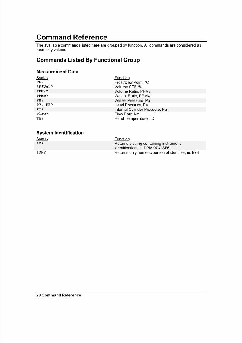
Command ReferenceThe available commands listed here are grouped by function. All commands are considered asread only values.
Commands Listed By Functional Group
Measurement Data
Syntax FunctionFP? Frost/Dew Point, °CSF6Vol? Volume SF6, %PPMv? Volume Ratio, PPMvPPMw? Weight Ratio, PPMwPX? Vessel Pressure, PaP?, PH? Head Pressure, PaPT? Internal Cylinder Pressure, PaFlow? Flow Rate, l/m
Th? Head Temperature, °C
System Identification
Syntax FunctionID? Returns a string containing instrument
identification, ie. DPM 973_SF6IDN? Returns only numeric portion of identifier, ie. 973
7/28/2019 973 Sf6 Manual
http://slidepdf.com/reader/full/973-sf6-manual 33/34
Mirror Cleaning 29
Maintenance
Mirror CleaningThe heart of the 973 dew point measuring instrument is the measuring head assembly. It isdesigned to be highly sensitive and accurate, yet rugged and easily accessible for periodic mirror cleaning.
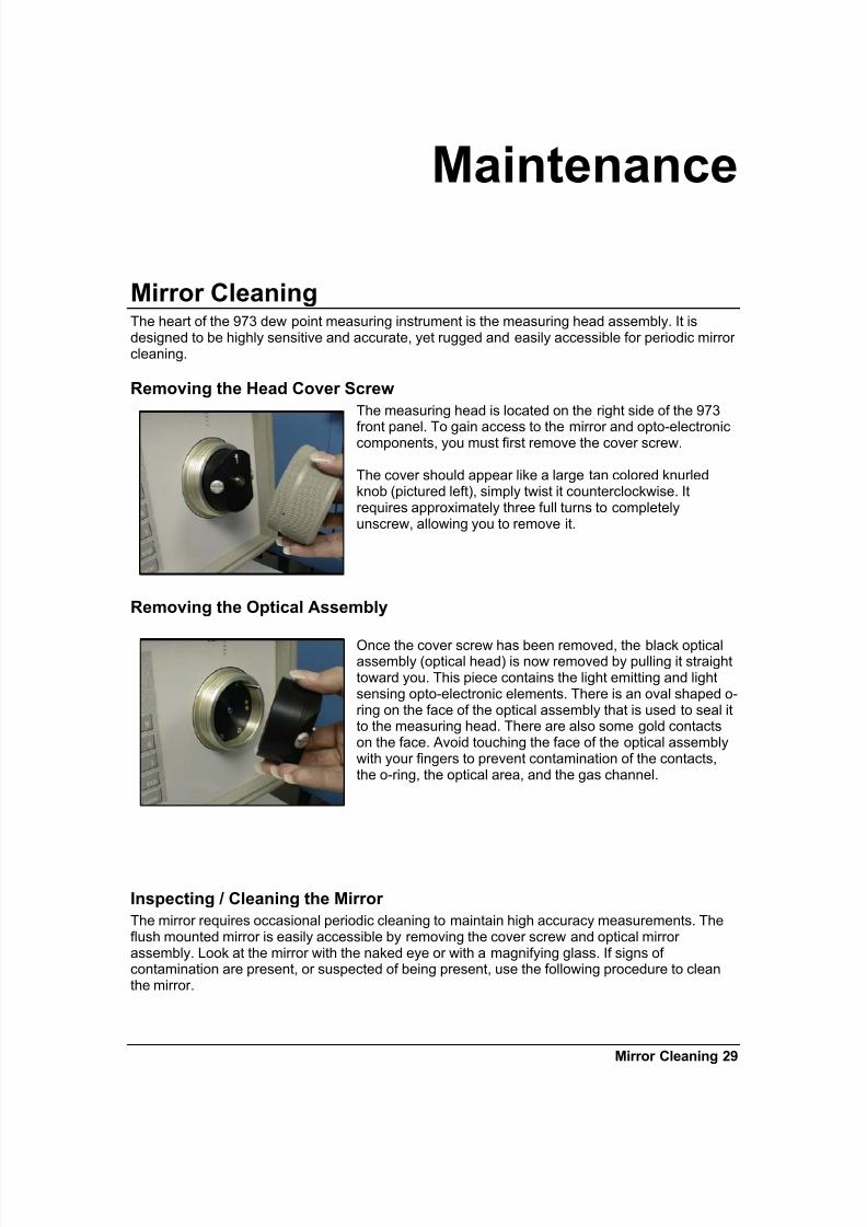
Removing the Head Cover Screw
The measuring head is located on the right side of the 973
front panel. To gain access to the mirror and opto-electroniccomponents, you must first remove the cover screw.
The cover should appear like a large tan colored knurledknob (pictured left), simply twist it counterclockwise. Itrequires approximately three full turns to completelyunscrew, allowing you to remove it.
Removing the Optical Assembly
Once the cover screw has been removed, the black opticalassembly (optical head) is now removed by pulling it straighttoward you. This piece contains the light emitting and lightsensing opto-electronic elements. There is an oval shaped o-ring on the face of the optical assembly that is used to seal itto the measuring head. There are also some gold contactson the face. Avoid touching the face of the optical assemblywith your fingers to prevent contamination of the contacts,the o-ring, the optical area, and the gas channel.
Inspecting / Cleaning the Mirror
The mirror requires occasional periodic cleaning to maintain high accuracy measurements. Theflush mounted mirror is easily accessible by removing the cover screw and optical mirror assembly. Look at the mirror with the naked eye or with a magnifying glass. If signs of contamination are present, or suspected of being present, use the following procedure to cleanthe mirror.
7/28/2019 973 Sf6 Manual
http://slidepdf.com/reader/full/973-sf6-manual 34/34
1. Clean the mirror with a clean cotton swab or lint freetissue dampened with distilled water.
2. Follow with a dry cotton swab or tissue.
Although a clean mirror is important to accuratemeasurements and sound measurement practices, pleasetake the following comments into consideration.
• Never attempt to polish the mirror. It is slightly roughened at the factory to allow for better nucleation sites and thus better dew formation.
• If needed, the mirror may also be cleaned with methanol or alchohol. Always follow the use of these cleaning chemicals with water to ensure they are completely rinsed form the mirror surface.
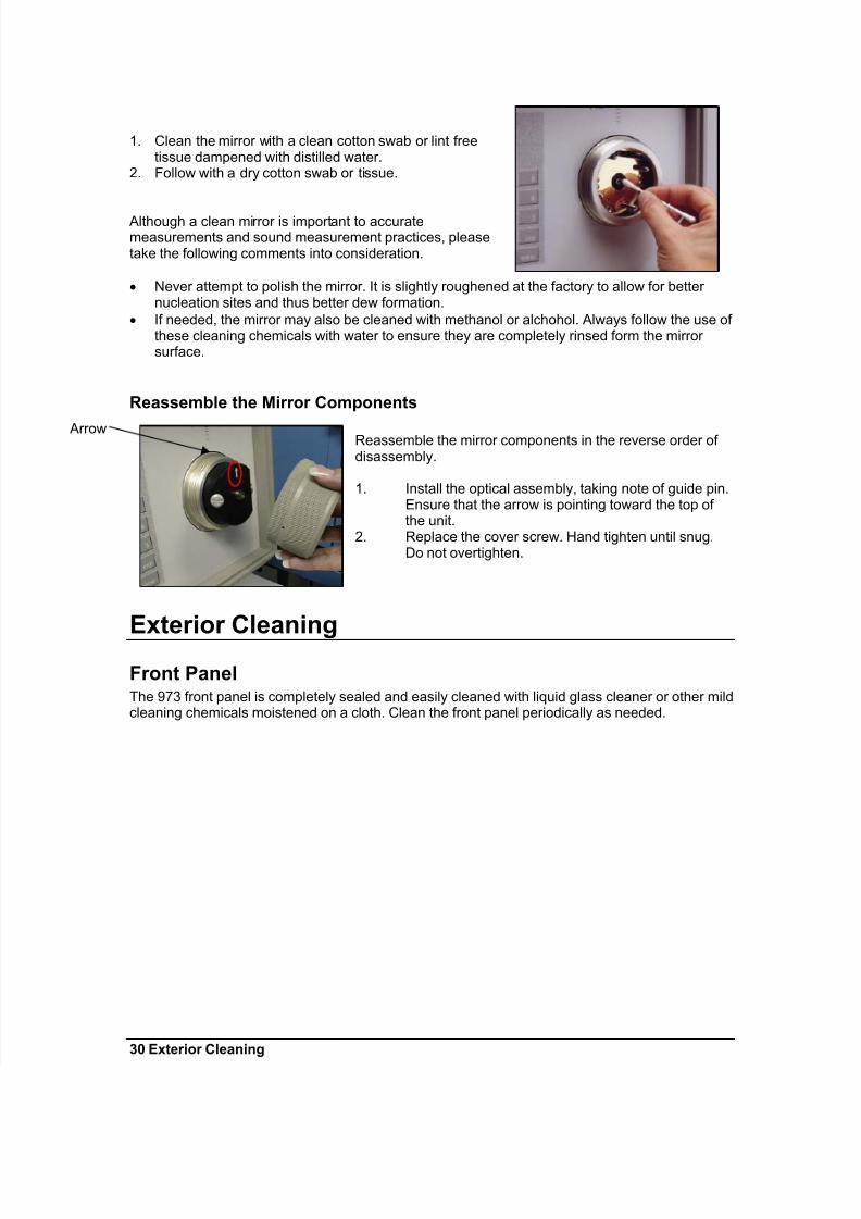
Reassemble the Mirror Components
Reassemble the mirror components in the reverse order of disassembly.
1. Install the optical assembly, taking note of guide pin.Ensure that the arrow is pointing toward the top of the unit.
2. Replace the cover screw. Hand tighten until snug.Do not overtighten.
Exterior Cleaning
Front PanelThe 973 front panel is completely sealed and easily cleaned with liquid glass cleaner or other mildcleaning chemicals moistened on a cloth. Clean the front panel periodically as needed.
Arrow