7. Heat Recovery Steam Generators - engsoft.co.kr · Thermal Fluid Techniques in Plants 7. HRSGs 8...
97
7. HRSGs 1 / 97 Thermal Fluid Techniques in Plants 7. Heat Recovery Steam Generators Condenser (heat out) T s Topping cycle Bottoming cycle Combustion (heat In) Stack (heat out)
Transcript of 7. Heat Recovery Steam Generators - engsoft.co.kr · Thermal Fluid Techniques in Plants 7. HRSGs 8...

7. HRSGs 1 / 97Thermal Fluid Techniques in Plants
7. Heat Recovery Steam Generators
Condenser
(heat out)
T
s
Topping cycle
Bottoming cycle
Combustion
(heat In)
Stack
(heat
out)

7. HRSGs 2 / 97Thermal Fluid Techniques in Plants
Investigation of HRSG Design Concepts 373
HRSG Performance 525
Introduction to HRSG 21
Type of HRSGs (Horizontal vs. Vertical) 312
Once-through HRSGs 414
SCR 916

7. HRSGs 3 / 97Thermal Fluid Techniques in Plants
A Typical HRSG [GE]

7. HRSGs 4 / 97Thermal Fluid Techniques in Plants
[ Horizontal Design ] [ Vertical Design ]
HRSG Configuration

7. HRSGs 5 / 97Thermal Fluid Techniques in Plants
HRSG Configuration
7. HRSGs 6 / 97Thermal Fluid Techniques in Plants
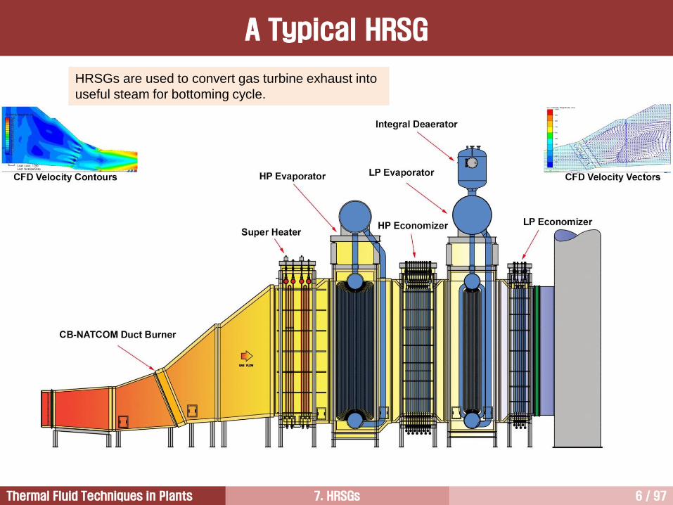
HRSGs are used to convert gas turbine exhaust into
useful steam for bottoming cycle.
A Typical HRSG

7. HRSGs 7 / 97Thermal Fluid Techniques in Plants
③
④②
①
Bottoming Cycle (Rankine Cycle)
T
s
compression of
water by pumps
condensation
of steam
feed water
heating in
economizer
vaporization
in evaporator
expansion of steam
in steam turbine
steam dome
superheating
in superheater

7. HRSGs 8 / 97Thermal Fluid Techniques in Plants
A common application of an HRSG is in a combined cycle power station, where hot exhaust from a gas
turbine is fed to an HRSG to generate steam which in turn drives a steam turbine. This combination
produces electricity more efficiently than either the gas turbine or steam turbine alone.
The HRSG is also an important component in cogeneration plants. Cogeneration plants typically have a
higher overall efficiency in comparison to a combined cycle plant because there is no energy loss associated
with the steam turbine.
Modular HRSGs can be categorized by a number of ways such as direction of exhaust gases flow or number
of pressure levels.
Based on the flow of exhaust gases, HRSGs are categorized into vertical and horizontal types. In horizontal
type HRSGs, exhaust gas flows horizontally over vertical tubes whereas in vertical type HRSGs, exhaust
gas flow vertically over horizontal tubes.
Based on pressure levels, HRSGs can be categorized into single pressure and multi pressure. Single
pressure HRSGs have only one steam drum and steam is generated at single pressure level whereas multi
pressure HRSGs employ two (double pressure) or three (triple pressure) steam drums. As such triple
pressure HRSGs consist of three sections: an LP (low pressure) section, a reheat/IP (intermediate pressure)
section, and an HP (high pressure) section. Each section has a steam drum and an evaporator section
where water is converted to steam. This steam past the saturation point then passes through superheaters
to raise the temperature further.
Generals for HRSG [1/2]

7. HRSGs 9 / 97Thermal Fluid Techniques in Plants
Some HRSGs include supplemental, or duct firing. These additional burners provide additional energy to the
HRSG, which produces more steam and hence increases the output of the steam turbine. Generally, duct
firing provides electrical output at lower capital cost. It is therefore often utilized for peaking operations.
HRSGs can also have diverter dampers to regulate in the inlet flow into the HRSG. This allows the gas
turbine to continue to operate when there is no steam demand or if the HRSG needs to be taken offline.
Emission controls may also be located in the HRSG. Some may contain a SCR(Selective Catalytic
Reduction) system to reduce nitrogen oxides (a large contributor to the formation of smog and acid rain)
and/or a catalyst to remove carbon monoxide.
The inclusion of an SCR dramatically affects the layout of the HRSG. NOx catalyst performs best in
temperatures between 650 °F (340 °C) and 750 °F (400 °C). This usually means that the evaporator section
of the HRSG will have to be split and the SCR placed in between the two sections.
Some low temperature NOx catalysts have recently come to market that allows for the SCR to be placed
between the Evaporator and Economizer sections (350 °F - 500 °F (175 °C - 260 °C)).
Generals for HRSG [2/2]

7. HRSGs 10 / 97Thermal Fluid Techniques in Plants
To reduce the velocity of gas turbine exhaust gas, the inlet duct of HRSG is diffuser type in both the
horizontal and vertical HRSGs, otherwise pressure drop through the HRSG would be excessive.
Inlet Duct
7. HRSGs 11 / 97Thermal Fluid Techniques in Plants
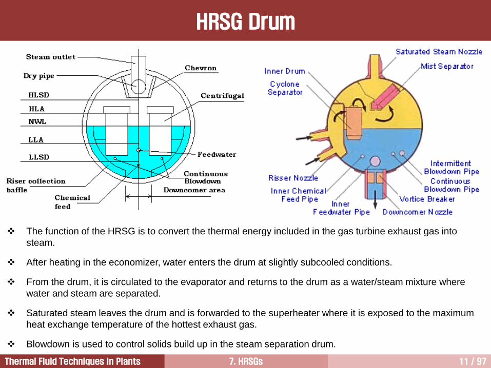
The function of the HRSG is to convert the thermal energy included in the gas turbine exhaust gas into
steam.
After heating in the economizer, water enters the drum at slightly subcooled conditions.
From the drum, it is circulated to the evaporator and returns to the drum as a water/steam mixture where
water and steam are separated.
Saturated steam leaves the drum and is forwarded to the superheater where it is exposed to the maximum
heat exchange temperature of the hottest exhaust gas.
Blowdown is used to control solids build up in the steam separation drum.
HRSG Drum
7. HRSGs 12 / 97Thermal Fluid Techniques in Plants
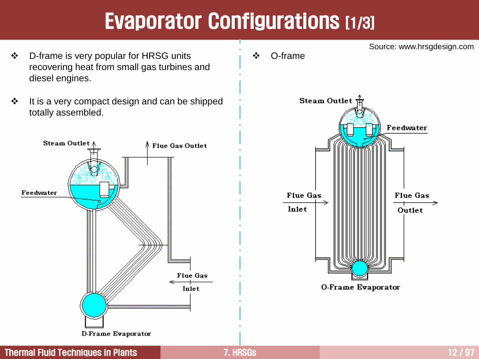
D-frame is very popular for HRSG units
recovering heat from small gas turbines and
diesel engines.
It is a very compact design and can be shipped
totally assembled.
Source: www.hrsgdesign.com
O-frame
Evaporator Configurations [1/3]
7. HRSGs 13 / 97Thermal Fluid Techniques in Plants
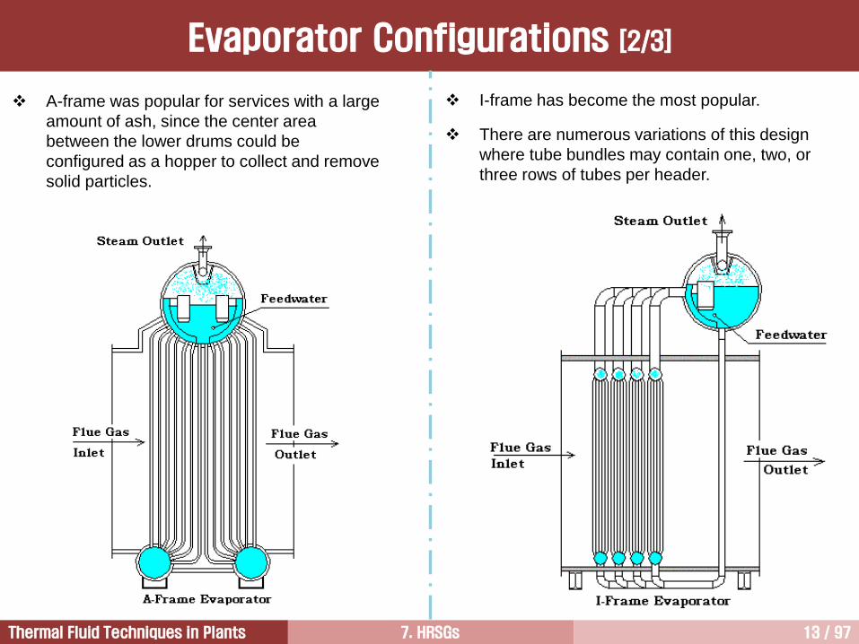
A-frame was popular for services with a large
amount of ash, since the center area
between the lower drums could be
configured as a hopper to collect and remove
solid particles.
I-frame has become the most popular.
There are numerous variations of this design
where tube bundles may contain one, two, or
three rows of tubes per header.
Evaporator Configurations [2/3]

7. HRSGs 14 / 97Thermal Fluid Techniques in Plants
Ref: www.hrsgdesign.comHorizontal Tube
Evaporator Configurations [3/3]

7. HRSGs 15 / 97Thermal Fluid Techniques in Plants
Superheater designs would normally follow along
with the evaporator type that is being used.
Three basic superheater designs are shown
above, horizontal tube, vertical tube, and I-frame.
The horizontal tube design would normally be
used for the D-frame evaporator if gas flow is
vertical up at the outlet.
This horizontal design would be expected to be
used also on a horizontal evaporator design.
The vertical tube design would generally be used
with the A-frame or O-frame evaporator and with
the D-frame if the gas exits horizontally.
The I-frame superheater would be used with the
I-frame evaporator, but may also be used with
the other evaporator designs.
Superheater Configurations

7. HRSGs 16 / 97Thermal Fluid Techniques in Plants
HRSG Header
7. HRSGs 17 / 97Thermal Fluid Techniques in Plants
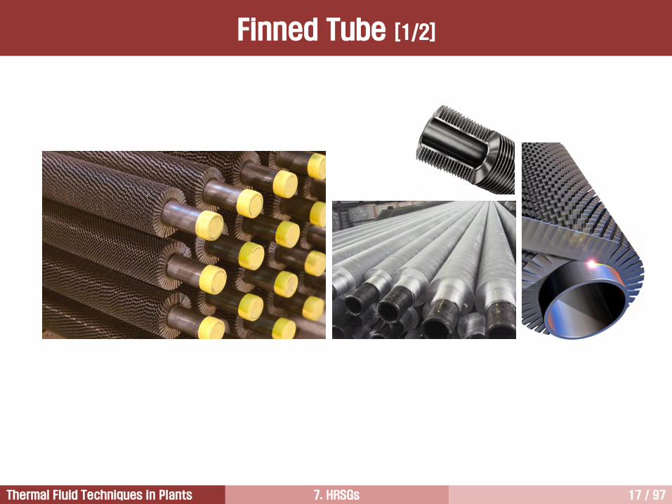
Finned Tube [1/2]

7. HRSGs 18 / 97Thermal Fluid Techniques in Plants
The tube wall temperature tend to run quite close to the water and steam side temperatures because water
side and steam side heat transfer coefficients are much higher.
Because flue gas side heat transfer rates are poor, tubes must be of small diameter, with tight spacing and
be of the finned type to provide sufficient heat transfer area.
The only section of the HRSG which might not use finned tubes is the HP superheater where there might be
a possibility of oxidation of the finning. (GE uses finned tube superheater)
High efficiency finning is desirable to reduce the size of the HRSG.
Fin material with a high conductivity is desirable.
Fin shape and pitch are also critical due to the need to prevent excessive pressure drop through the HRSG,
otherwise gas turbine output will suffer. (the overall pressure drop across the whole HRSG should not be
much more than 25 mbar)
Normally, the fin density is 5 to 7 fins per inch when natural gas or No. 2 oil use as fuels.
When the heavier fuels are used, the fin density is reduced to 3 to 4 fins per inch due to fouling.
A potential problem with finning, where different types of materials are employed, is expansion differences
leading to thermal fatigue.
Finned Tube [2/2]
Typical HRSG Heat Transfer Coefficient, W/m2K
Flue Gas Water in Economizer Water in Evaporator HP Steam
50 500 2500~10000 1000

7. HRSGs 19 / 97Thermal Fluid Techniques in Plants
An exhaust bypass stack is a prerequisite for phased installation of a combined cycle plant – one in which
the gas turbine runs in simple-cycle operation before the steam cycle is connected.
However, this feature is less important in modern gas turbines because
• the design is expensive with gas turbine exhaust temperatures of 600C and above.
• if the damper fails, the entire plant must be shut down.
• an exhaust damper has leakage losses with resultant losses in output and efficiency.
• the associated cost are significant.
[ with Bypass Stack ] [ without Bypass Stack ]
Bypass Stack

7. HRSGs 20 / 97Thermal Fluid Techniques in Plants
HRSGs are gas-to-water heat exchanger systems that extract energy from the gas turbine exhaust gases to
generate steam. That is, HRSGs are used to convert the energy contained in the gas turbine exhaust gas
into useful steam for the bottoming portion of the combined cycle.
The steam can be generated over a wide range of pressures and temperatures for a variety of uses such as
process steam, district heating, or driving steam turbine for power generation.
Many HRSG configurations may be considered when designing a combined cycle.
In many combined cycle applications, steam is generated at several pressures to make the most
advantageous use of the energy available.
Reheat cycles are also feasible because of the higher exhaust gas temperatures available from advanced
gas turbine technologies, such as advanced metallurgy, improved cooling technologies, and increased
pressure ratio.
More steam pressure sections can be designed into the HRSG, making it more complicated and more
expensive but with improved recovery of the exhaust heat.
The steam cycle design depends on the economics of the application and the project specific requirements.
HRSG [1/2]

7. HRSGs 21 / 97Thermal Fluid Techniques in Plants
The maximum temperature and pressure of the steam generated in an HRSG are governed by the gas
turbine EGT (assuming that the HRSG is not supplementary fired).
The higher the EGTs, the higher steam temperatures and pressures. In the combined cycle units, the higher
steam temperatures/pressure, the lower heat rates.
This is the reason why heavy duty gas turbines are more commonly used in combined cycle units.
Normally, aeroderivative gas turbines have EGTs in the range of 800 to 950F. By contrast, current heavy
duty gas turbines generally have EGTs of 950 to 1,100F.
Exhaust heat, thermal energy contained in the exhaust gas flow, is the product of the exhaust gas flow and
the exhaust gas enthalpy.
Exhaust heat can be estimated by calculating a heat balance around the gas turbine. By this method,
exhaust heat is calculated as the heat input from fuel, inlet air, and injection water/steam, minus the thermal
equivalent of the generator output and miscellaneous losses (including generator losses and
turbine/generator bearing losses).
Some manufacturers do not guarantee exhaust flow or temperature, but they do guarantee exhaust heat.
This guarantee is significant for heat recovery applications only.
HRSG [2/2]

7. HRSGs 22 / 97Thermal Fluid Techniques in Plants
Three Pressure
Reheat Cycle
Steam Cycle
Condenser
G
G
Fuel
Air
Gas turbine
Heat recovery steam
generator
IP steam LP
steamCold reheat
steam
Hot reheat
steam
Main
steam
Steam turbine
Condensate pump
Steam
Water
Fuel
Air

7. HRSGs 23 / 97Thermal Fluid Techniques in Plants
Inlet Duct
From Gas Turbine
Spiral Fin Tube
De-NOx Catalyst
Exhaust
Duct
LP DrumIP DrumSilencer Assembly
HP Drum
Low-temperature corrosion must be
prevented stack gas temp. 80C
Heat recovery must be high
finned tubes
Pressure drop on the gas side should be
low diffuser type inlet duct
The permissible pressure gradient during startup
must be steep once-through HRSG
A Typical HRSG Requirements

7. HRSGs 24 / 97Thermal Fluid Techniques in Plants
HRSG Configuration

7. HRSGs 25 / 97Thermal Fluid Techniques in Plants
Distance along HRSG
Te
mp
era
ture
EvaporatorPP
ATE (Sub-cool)
Pinch point can be optimized by evaluating the equipment
cost and operating cost. Small pinch point requires large
heating surface and results is higher cycle efficiency.
PP = Pinch point in boiler
ATS = Approach temperature in
superheater
ATE = Approach temperature in
economizer
ATS
Pinch Point & Approach Temperature [1/6]

7. HRSGs 26 / 97Thermal Fluid Techniques in Plants
The pinch point is defined as the difference between the exhaust gas temperature leaving the evaporator
section and the saturation temperature of the steam.
The lower the pinch point, the more the heat recovered, but this requires larger heat transfer surface area and,
consequently, increases the pressure drop in HRSG and cost. Therefore, the pinch point selection can greatly
affect the physical size of the HRSG.
Moreover, excessively low pinch points can mean inadequate steam production if the exhaust gas is low in
energy (low mass flow or low EGT).
Pinch points are typically between 8 and 15C (14 to 27F), depending on the economic parameters of the
plant.
The approach temperature is the difference between the saturation temperature of the steam and the water
temperature at the economizer outlet.
The smaller approach temperature, the better heat utilization, but increased heat transfer surfaces and cost.
Convervatively, high approach temperatures ensure that no steam generation occurs in the economizer.
Typically, approach temperatures are in the range of 5 to 12C (9 to 22F), helps to avoid evaporation in the
economizer at off-design conditions.
For a drum-type HRSG, a lower limit is set on the approach temperature to minimize steaming in the
economizers for off design points. Normally, a lower limit is 5C.
Pinch Point & Approach Temperature [2/6]

7. HRSGs 27 / 97Thermal Fluid Techniques in Plants
Energy transfer, MW
Tem
pera
ture
, C
HP/IP Economizer
HP Evaporator
IP Evaporator
LP Evaporator
HP Superheater
/Reheater
HP Economizer
/IP Superheater
HP/IP/LP Economizer
700
600
500
400
300
200
100
00 50 100 150 200 240
Three Pressure
Reheat Cycle
Pinch Point & Approach Temperature [3/6]

7. HRSGs 28 / 97Thermal Fluid Techniques in Plants
Effect of pinch point on relative steam turbine power
output and relative HRSG heating surface (relative pinch
point = 12K)
The surface of the evaporator increases
exponentially as the pinch point
decreases, whereas the increase in
steam generation is linear.
For this reason, the pinch point selected
is a critical factor in determining the heat
transfer surface.
The lower the pinch point, the higher
steam turbine output.
In order to reduce the pinch point, the
surface of heat exchanger increases as
the pinch point becomes zero.
HRSG having higher efficiency has the
pinch point of 8~14K, but the pinch point
of lower efficiency HRSG can be higher,
15~25K.
Pinch Point & Approach Temperature [5/6]

7. HRSGs 29 / 97Thermal Fluid Techniques in Plants
The flue gas leaving the evaporator enters into economizer.
If same T between EGT and the water maintained, boiling would occur at the exit of economizer.
This would result in a “steaming economizer” with the possibility of the flow being blocked.
It is clear that if the water flow is blocked, all the water in the economizer would begin to turn into steam.
In this case, tubes would subject to a overheating, however, the main problems would be water hammering
and tube-to-tube differential expansion.
Accordingly, the outlet water temperature in the economizer should be keep several degrees below the
saturation temperature.
This can be done by cutting down the economizer heating surfaces and imposing part of the LP superheater
between the HP evaporator and economizer.
The approach temperature might be 4C, so this when added to a pinch point temperature of 8C, would
give an overall temperature differential of 12C, greatly reducing the risks of boiling.
Pinch Point & Approach Temperature [6/6]

7. HRSGs 30 / 97Thermal Fluid Techniques in Plants
Three-pressure single reheat.
High pressure level – the existing economic optimum is 130 bar, although the thermal optimum lies well
above (180 bar) for three-pressure reheat HRSG.
Economic optimum steam temperature is 565C (1050F), and above 600C are available.
Steam output – defined by the economic determination of the pinch point (6 to 8K) at the HP evaporator and
the approach temperature at the economizer (2 to 4K), typically 74 kg/s without supplementary firing and
120 kg/s with supplementary firing.
Finned tubes have been employed to keep the pinch point as low as possible.
Feedwater (condensate) inlet temperature with respect to type of fuel used, above 50C for natural gas with
no sulfur content, and above 110C for light distillate oil to ensure operation above acid or water dew point.
Stack temperature of minimum 80C.
The purity of steam entering superheater is 99.9%.
HRSG flue gas draft loss is approximately 25 mbar, 35 mbar if catalysts are required.
The key components, those performance is critical, are high pressure steam piping headers and superheater
tubes. All these components have to meet creep strength requirements, but thermal fatigue resistance and
weldability are also important.
Current Requirements for HRSGs

7. HRSGs 31 / 97Thermal Fluid Techniques in Plants
Investigation of HRSG Design Concepts3
HRSG Performance5
Introduction to HRSG1
Type of HRSGs (Horizontal vs. Vertical)2
Once-through HRSGs4
SCR6

7. HRSGs 32 / 97Thermal Fluid Techniques in Plants
Multi-Shaft CCPP (207FA)
2-on-1 Configuration
Single-Shaft CCPP (107FA)
1-on-1 Configuration
CCPP Arrangement

7. HRSGs 33 / 97Thermal Fluid Techniques in Plants
The horizontal HRSGs are typically known as natural-circulation HRSGs because circulation through the
evaporator takes place entirely by gravity, based on the density difference of water and boiling water
mixtures.
The heat transfer tubes are vertical, and self-supporting on the ground.
Today, the horizontal HRSGs are preferred.
Horizontal Design

7. HRSGs 34 / 97Thermal Fluid Techniques in Plants
The vertical HRSGs were known as forced-circulation HRSGs because of the use of circulation pumps to
provide positive circulation of boiler water through the evaporator sections.
However, the vertical HRSG no longer requires forced-circulation pumps, not even for start up, because the
design of evaporator was improved.
Vertical Design

7. HRSGs 35 / 97Thermal Fluid Techniques in Plants
Horizontal Vertical
Output and efficiency Equal
Surface area for
equal output
Similar, except the reheater and
superheater section which might require
slightly more heating surface area mainly
due to less effective flue gas distribution
Plan area for equal
output
Up to 30% more, mainly due to the
opening angle of the inlet duct and the
stack, and if supplementary firing systems,
SCRs, CO catalysts, etc. are required
Emission control Requires more HRSG length
Requires more HRSG height, cleaning of
downstream fouled surfaces has to be
carried out carefully, not to poison the
catalyst
Supplementary firingReadily installed in the HRSG inlet duct or
within the boiler surface area
Readily installed in the HRSG inlet duct,
difficult to install within the boiler surface
area
HRSG enclosure /
Boiler houseFree standing, self supporting enclosure
Attached to and supported by the HRSG
structure, light enclosure
Circulation Natural Forced (Natural type is available)
Horizontal vs. Vertical HRSG [1/2]

7. HRSGs 36 / 97Thermal Fluid Techniques in Plants
Horizontal Vertical
Modularized Typical
Erection area,
prefabrication on site
Equal, though more crane area is required
for pressure parts mounting which
typically lasts 5 weeks for large GT CCPP
Equal, though heavy transportation (120
tons) may be required on site, typical
time needed for boiler surface mounting:
3 weeks for large GT CCPP
Cycling
State of the art design experiences severe
cycling problems at superheater and
reheater stages, design considerations
cost effective
Less vulnerable if properly designed
HRSG cost (ready to
run)Equal
O&M cost
Higher number of and larger textile
expansion joints, boiler surface
replacements not possible, repair by
blocking of tubes, cost effective
Replacement and blocking of tubes
possible
Regular inspectionsInspection of headers and surfaces is not
easy
Inspection of header and surface can be
performed easily because of easy
accessing through manholes
Horizontal vs. Vertical HRSG [2/2]

7. HRSGs 37 / 97Thermal Fluid Techniques in Plants
Investigation of HRSG Design Concepts3
HRSG Performance5
Introduction to HRSG1
Type of HRSGs (Horizontal vs. Vertical)2
Once-through HRSGs4
SCR6

7. HRSGs 38 / 97Thermal Fluid Techniques in Plants
HRSG should absorb the rapid thermal expansion caused by quick startup of the gas turbine.
The main constraint of the loading gradient is often governed by the drum.
The walls of the drum should be as thin as possible for shorter startup times.
However, advanced gas turbines have higher EGT than older ones, therefore, higher steam pressures are
more attractive and this results in longer startup times.
Once-through HRSGs eliminate the thick high pressure drum, which is the main obstacle for shorter startup
times in high pressure HRSGs.
Another concern is the volumetric change in the evaporator during startup.
The large difference in specific volume between steam and water at low and intermediate pressures cause
large amount of water to be expelled from the evaporator at the onset of the evaporation process.
If the drum cannot accommodate most of this water, a large amount of water would be lost through
emergency drain of the drum during every startup, or an undesired emergency trip of the unit would be
required to prevent water carryover into the steam system.
HRSG Design [1/3]

7. HRSGs 39 / 97Thermal Fluid Techniques in Plants
HRSG is operated in sliding-pressure mode to improve part load efficiency.
In a system with two gas turbines and two HRSGs feeding a common steam turbine, half-load of the whole
power station can be accomplished with only one of the gas turbines running at full load.
In sliding-pressure mode, the steam pressure is at 50% of the pressure at full load.
The steam volumes in the evaporator, superheater, and steam lines of the HRSG in operation are doubled.
HRSG flue gas draft losses: approximately 25 mbar, 35 mbar if catalysts are required.
Stack temperature: 80C (to avoid corrosion due to corrosion elements having lower dew points).
Rankine cycle: triple pressure single reheat.
Once-through boilers are subject to FAC (Flow Assisted Corrosion).
In order to avoid to deposition of solids in the evaporator, once-through boilers have to use as AVT (All
Volatile Treatment).
Tube surfaces are then susceptible to erosion by two phase, high velocities, leading to FAC, as can occur in
the low pressure units of the HRSG.
HRSG Design [2/3]

7. HRSGs 40 / 97Thermal Fluid Techniques in Plants
Key Factor Unit Value Limiting Factor
Main steam temp. C 567 Steam turbine
Operating steam pressure Bar 170 Start-up time 60 min
HP evaporator pinch points K 6 Economics, accuracy of thermal design
HP economizer approach
point
K 3 (0) Horizontal (vertical, due to the height benefit)
HP superheated steam vel. m/s 70 Sound, economics
HP saturated steam vel. m/s 20 Erosion, corrosion, economics
Two-phase velocity m/s 10 FAC, economics
Water velocity m/s 2-4 FAC, economics
Noise dbA 90 GT emission, sound enclosure
Supplementary firing % +50 Flow distribution and properties, flue gas temperature
in case of the vertical type HRSG
Cold starts - Weekly Gradients of thick walled components
Cycling rate MW/ min None GT load changes
FAC: Flow Assisted Corrosion
Limiting Key Factor
HRSG Design [3/3]

7. HRSGs 41 / 97Thermal Fluid Techniques in Plants
Investigation of HRSG Design Concepts3
HRSG Performance5
Introduction to HRSG1
Type of HRSGs (Horizontal vs. Vertical)2
Once-through HRSGs4
SCR6

7. HRSGs 42 / 97Thermal Fluid Techniques in Plants
In a once-through steam generator, the economizer, evaporator, and superheaters are basically one tube,
eliminating the drum and circulating pumps.
This design has advantages at higher steam pressure because the drum does not impose limits during
startups and load changes.
Both horizontal and vertical HRSGs can be built with once-through type.
There are two primary concerns in terms of HRSG design for fast start:
1. Component failure
a. high steam conditions require thick component walls
b. fast start-up results in high thermal gradients in the walls
c. component fail after fatigue life is consumed
2. Drum level control
a. gas turbine start-up produces rapid boiling in the evaporator
b. if water level in the drum rises to the separators, water carry over into the superheater may occur
c. the typical response to this is to either trip or slow gas turbine load ramp
Once-through HRSG eliminates the thick wall HP drum and allows an unrestricted gas turbine start-up
Once-through HRSG

7. HRSGs 43 / 97Thermal Fluid Techniques in Plants
Drum Type vs. Once-through

7. HRSGs 44 / 97Thermal Fluid Techniques in Plants
[ Start-up curves after overnight outage ]
Siemens
Question: Why fast startup is important in terms of emission ?
The term Benson boiler is a
design that is capable of
operating on a variable
pressure ramp and is capable
of start up from zero pressure
at initial firing and up to
supercritical pressure at
higher load.
Benson boiler has a better
operational flexibility.
Once-through HRSG

7. HRSGs 45 / 97Thermal Fluid Techniques in Plants
There has also been a debate over the years whether the once-through HRSG technology should be better
off than drum boilers in terms of cycling.
GE
• Detailed transient analysis showed that the majority of fatigue life consumption occurs
at the hottest high pressure superheater and reheater during fast gas turbine loading,
regardless of whether the HRSG uses high pressure drum or once through technology.
• The HRSG stack is equipped with an automatic damper that closes upon plant
shutdown to reduce HRSG heat loss and the time required for next plant start-up, as
well as reduce the cyclic stress of the start.
Siemens
• Once-through HRSG eliminates the thick wall HP drum and allows an unrestricted gas
turbine start-up
a. gas turbine start-up produces rapid boiling in the evaporator
b. if water level in the drum rises to the separators, water carry over into the
superheater may occur
c. the typical response to this is to either trip or slow gas turbine load ramp
It is hard to conclude that which one is better in terms of operating flexibility
Operating Flexibility

7. HRSGs 46 / 97Thermal Fluid Techniques in Plants
Most once-through designs for CCPP are subcritical.
Steam bubbles are generated in the evaporator.
During base load operation the steam existing the evaporator section will have a mild degree of superheat
and should enter the superheater in a completely dry condition.
During startup, the steam from the evaporator will not only be saturated but also will superheated.
This needs to be removed in a separator.
Once-through HRSG
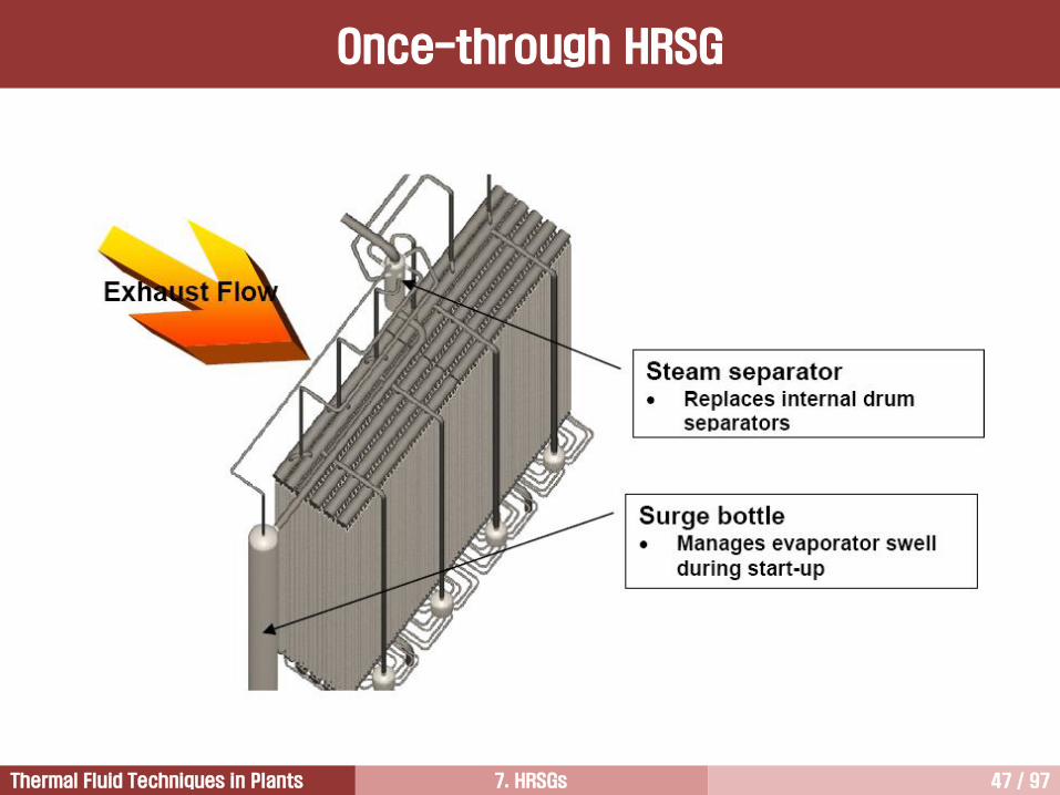
7. HRSGs 47 / 97Thermal Fluid Techniques in Plants
Once-through HRSG

7. HRSGs 48 / 97Thermal Fluid Techniques in Plants
Advanced HRSGs are of a three-
pressure reheat configuration with high-
pressure section in a once-through
design, and intermediate- and low-
pressure sections as drum-type
evaporators.
Once-through HRSG

7. HRSGs 49 / 97Thermal Fluid Techniques in Plants
Water consumption in the water/steam cycle can be reduced by the employment of once-
through HRSGs
In a drum type HRSG, some amount of water need to be blown down out of the drums to
achieve the required steam purity.
This water needs to be replaced by demineralized water.
The once-through HRSG, which does not have drums, the cleaning is done by a condensate
polishing plant. Therefore, the amount of water wasted is much less.
Once-through HRSG

7. HRSGs 50 / 97Thermal Fluid Techniques in Plants
Flow diagram of a high-pressure reheat cycle with a HP once-through
HRSG and a drum-type LP section.
This cycle has no feedwater
tank, so deaeration takes place
in the condenser.
Once-through HRSG

7. HRSGs 51 / 97Thermal Fluid Techniques in Plants
Once-through HRSG
국내 설치 현황 (Units): GS EPS, 당진 (1); SK E&S, 장문 (4); 포스코에너지 (3); 대구그린파워 (1); S-Power, 안산(2); 남부발전, 안동 (1) (SGT6-8000H)

7. HRSGs 52 / 97Thermal Fluid Techniques in Plants
Investigation of HRSG Design Concepts3
HRSG Performance5
Introduction to HRSG1
Type of HRSGs (Horizontal vs. Vertical)2
Once-through HRSGs4
SCR6

7. HRSGs 53 / 97Thermal Fluid Techniques in Plants
Fuel Energy
100%
GT 37.6%
ST 21.7%C
on
de
nse
r
31.0%
Stack8.6%
Loss in HRSG
0.3%
Loss
0.5%
Loss
0.3%
Three Pressure
Reheat Cycle
Energy Flow Diagram

7. HRSGs 54 / 97Thermal Fluid Techniques in Plants
The power output and efficiency of the gas
turbine is strongly affected by its
backpressure.
Therefore, the pressure loss occurred in
the flue gas side of HRSG should be
minimized.
Lower pressure losses can get through
lower flue gas velocities around the tube
bundle leading to larger HRSG surface.
Typical pressure losses on the flue gas
side are between 25 to 30 mbar.
Influence of HRSG backpressure
on combined cycle output and
efficiency
Pressure Loss on the Flue Gas Side

7. HRSGs 55 / 97Thermal Fluid Techniques in Plants
HRSG Efficiency vs. EGT
EGT increases with TIT. The HRSG efficiency increases with EGT.

7. HRSGs 56 / 97Thermal Fluid Techniques in Plants
The corrosion, caused by water vapor and sulfuric acid in the exhaust gas, occurs whenever the gas is
cooled below the acid dew point of these vapors.
All surfaces that come into contact with the exhaust must be at a temperature above or slightly below the
sulfuric acid dew point.
The tube surface temperature on the exhaust gas side is approximately the same as the water or steam
temperature because the heat transfer on the exhaust gas side is inferior to that on the steam or water side.
Therefore, if tubes are to be protected against an attack of low temperature corrosion, feedwater
temperature must remain approximately as high as the acid dew point.
If the feedwater temperature is too low, a high stack temperature for the exhaust gases does not helpful.
Low temperature corrosion can also occur even when fuel containing no sulfur if the temperature drops
below the water dew point, that is between 40 and 45C.
In case of gas fuel with very low sulfur content (<3ppm sulfur in fuel), a feedwater temperature is around
60C.
Oil tends to have higher sulfur, resulting in feedwater temperatures of around 120 to 160C.
For high sulfur fuels (normally backup fuels), the economizer is bypassed and the water enters directly into
the low-pressure drum.
Sulfur oxides in combination with excess air raise the dew point temperature very significantly, producing
liquid sulfuric acid at well above the dew point temperature. Gas turbine exhaust ducts and HRSGs can be
quickly corroded in this way.
Low Temperature Corrosion

7. HRSGs 57 / 97Thermal Fluid Techniques in Plants
0.01 0.05 0.1 0.5 1.0 10.05.0240
260
280
300
320
340
360
380
Dew Points for Sulfur Free Flue Gas
% Excess Air Dew Point (F)
0 138
10 135
20 131
Excess Air Range 5~20%
Weight % H2S in Fuel Gas
Dew
Poin
t Tem
pera
ture
, F
Acid Dew Point of Flue Gas
Maximum flue gas dew point versus percent H2S in typical gas fuels

7. HRSGs 58 / 97Thermal Fluid Techniques in Plants
0.01 0.05 0.1 0.5 1.0 10.05.0210
230
250
270
290
310
330
350
Dew Points for Sulfur Free Flue Gas
% Excess Air Dew Point (F)
0 116
15 112
30 108
Excess Air Range 10~30%
Weight % Sulfur in Fuel Oil
Dew
Poin
t Tem
pera
ture
, F
Acid Dew Point of Flue Gas
Maximum flue gas dew point versus percent sulfur in typical oil fuels

7. HRSGs 59 / 97Thermal Fluid Techniques in Plants
Three Pressure
Reheat Cycle
Flow Diagram
G
Natural gas
G
IP
9
HP
8
LP
10
1
2
3
4
5
6
7
11 12
13
14
1516
17
18
19 201 Dual HP superheater/reheater2,4,6 HP,IP,LP evaporators3 HP economizer/IP superheater5,7 Dual HP/IP economizer8,9,10 HP,IP,LP drums11 HP steam turbine12 IP/LP steam turbine13,14,15 HP,IP,LP steam bypasses16 Condenser17 Condensate pump18 Deaerator19,20 IP,HP feedwater pumps
7. HRSGs 60 / 97Thermal Fluid Techniques in Plants
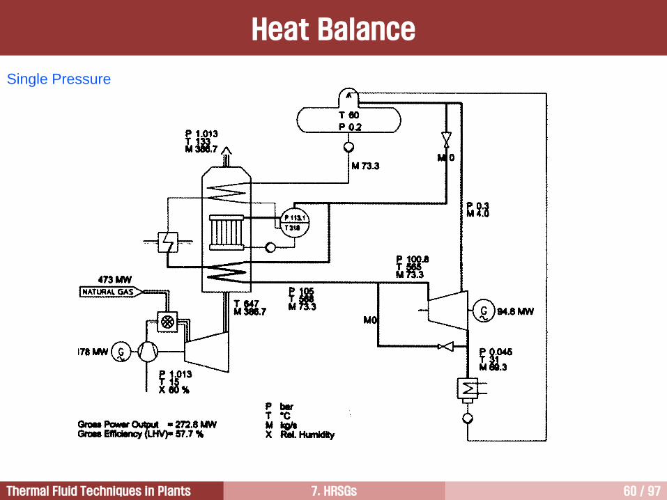
Single Pressure
Heat Balance

7. HRSGs 61 / 97Thermal Fluid Techniques in Plants
Single Pressure (GE)
Single pressure system does not produce
the highest efficiency.
Economical election:
• when fuel is inexpensive
• when applied in peaking type service
• when burning ash-bearing fuel with high
sulfur content
The HRSG stack gas temperature with this
steam cycle is approximately 171C.
Heat Balance

7. HRSGs 62 / 97Thermal Fluid Techniques in Plants
Two Pressure
Heat Balance

7. HRSGs 63 / 97Thermal Fluid Techniques in Plants
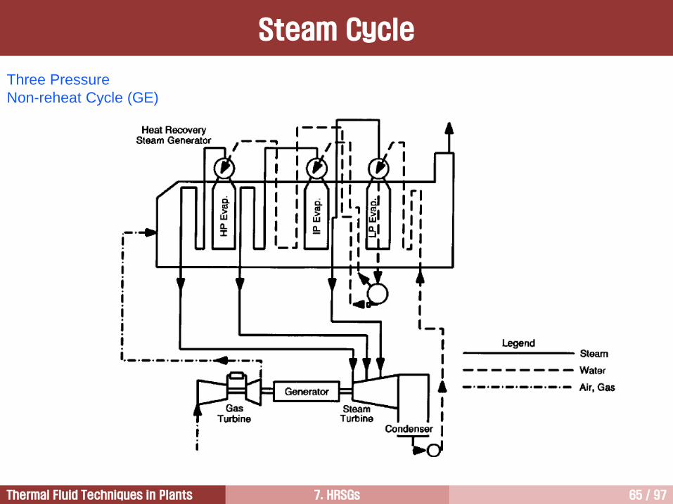
Three Pressure
Non-reheat Cycle
Two- or three-pressure cycles achieve
better efficiency than single pressure
systems, but their installed cost is
higher.
Economic choice when fuel is
expensive.
The HRSG stack gas temperature is
range of 93C to 127C.
Heat Balance

7. HRSGs 64 / 97Thermal Fluid Techniques in Plants
Three Pressure
Non-reheat Cycle
Flow Diagram
7. HRSGs 65 / 97Thermal Fluid Techniques in Plants
Three Pressure
Non-reheat Cycle (GE)
Steam Cycle

7. HRSGs 66 / 97Thermal Fluid Techniques in Plants
Three Pressure
Reheat Cycle
Heat Balance
Air
G
Natural gas
473 MW
G
P 33.7
T 240
P 33.7
T 240
P 33.7
T 240
P barT CM kg/sX Rel. humidity
Gross output = 280.5 MW
Gross effi. (LHV) = 59.3%
P 1.013T 15X 60 %
P 0.045T 31M 67
P 28.5T 565M 65.1
P 115.2T 565M 59.2
P 120T 568
P 30.0 T 568
P 32.1T 369M 5.9 P 4.6
T 150M 5.4
M 0
M 0
P 5.0T 152M 5.4
M 11.3 M 59.2
M 0
M 3.5
P 0.2T 60
P 1.013T 103M 386.7
T 647M 386.7
178 MW
M 0
102.5 MW
7. HRSGs 67 / 97Thermal Fluid Techniques in Plants
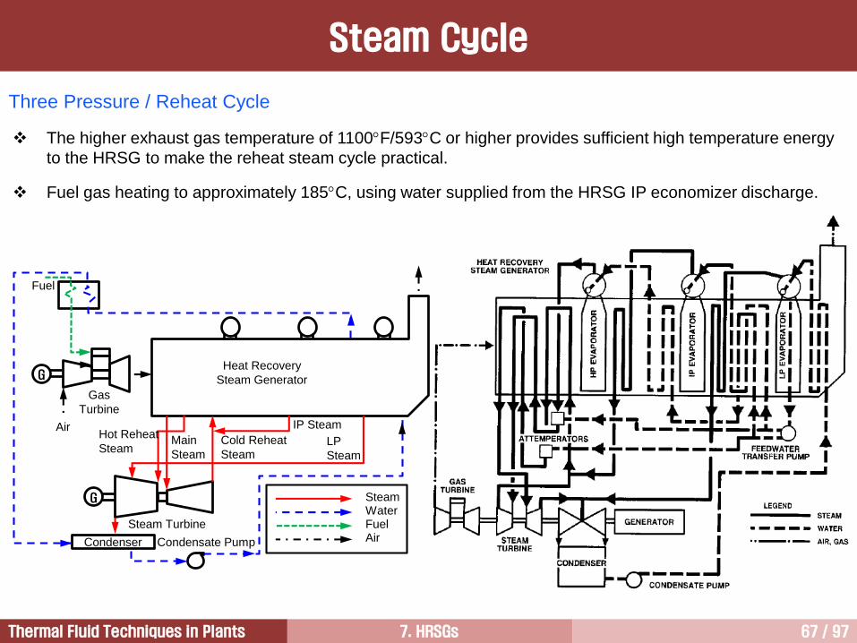
Three Pressure / Reheat Cycle
Condenser
G
G
Fuel
Air
Gas
Turbine
Heat Recovery
Steam Generator
IP Steam
LP
Steam
Cold Reheat
Steam
Hot Reheat
SteamMain
Steam
Steam Turbine
Condensate Pump
SteamWaterFuelAir
The higher exhaust gas temperature of 1100F/593C or higher provides sufficient high temperature energy
to the HRSG to make the reheat steam cycle practical.
Fuel gas heating to approximately 185C, using water supplied from the HRSG IP economizer discharge.
Steam Cycle

7. HRSGs 68 / 97Thermal Fluid Techniques in Plants
Single Pressure
Supplementary Firing
Heat Balance

7. HRSGs 69 / 97Thermal Fluid Techniques in Plants
Single Pressure
Supplementary Firing
Backpressure Turbine
Heat Balance

7. HRSGs 70 / 97Thermal Fluid Techniques in Plants
Unit 1-Press 2-Press3-Press/
Non-reheat
3-Press/
Reheat
Energy flow
GT % 37.6 37.6 37.6 37.6
ST % 20.1 21.0 21.1 21.7
Condenser % 29.9 32.1 32.0 31.0
Stack % 11.4 8.2 8.2 8.6
Stack Temperature C 133 96 96 103
GT Output MW 178 178 178 178
ST Output MW 94.8 99.0 99.7 102.5
Main Steam Pressure bar 105 105 105 120
Main Steam Temperature C 568 568 568 565
Moisture at Turbine Exhaust % 16 16 16 10
Comparison of Cycle Performance [1/3]

7. HRSGs 71 / 97Thermal Fluid Techniques in Plants
Unit 1-Press 2-Press 3-Press3-Press/
Reheat
1-Press/
S-Firing
GT Fuel Input (LHV) MW 473 473 473 473 473
Duct Burner Fuel Input (LHV) MW 0 0 0 0 51
Total Fuel Input (LHV) MW 473 473 473 473 524
GT Output MW 178 178 178 178 178
ST Output MW 94.8 99 99.7 102.5 125.5
Gross Plant Output MW 272.8 277 277.7 280.5 303.5
Gross Efficiency (LHV) % 57.7 58.6 58.7 59.3 57.9
Auxiliary Consumption MW 4.1 4.5 4.5 4.6 5.0
Net Plant Output MW 268.7 272.5 273.2 275.9 298.5
Net Efficiency (LHV) % 56.8 57.6 57.8 58.3 57.0
Net Heat Rate (LHV) kJ/kWh 6337 6249 6233 6712 6320
Net Heat Rate (LHV) Btu/kWh 6006 5923 5908 5850 5990
Total Relative Plant Cost % 100 104 106 112
Comparison of Cycle Performance [2/3]
7. HRSGs 72 / 97Thermal Fluid Techniques in Plants
Comparing two-pressure cycle with single-pressure cycle, the two-pressure cycle makes better use of
exhaust gases in the HRSG, resulting in a higher steam turbine output.
Comparing three-pressure cycle with two-pressure cycle, the three-pressure cycle has a only slightly higher
steam turbine output. This is because IP flow is very small.
In a three-pressure HRSG, the HP flow is 72.5 kg/s. However, the IP and LP flows are very small, only 3.1
kg/s and 3.0 kg/s, respectively. This fact is the same as in two-pressure HRSG.
Three-pressure reheat cycle has an advantage of a reduced moisture content and an improvement in the
performance.
Notes for Different Pressure Cycles
Comparison of Cycle Performance [3/3]
7. HRSGs 73 / 97Thermal Fluid Techniques in Plants
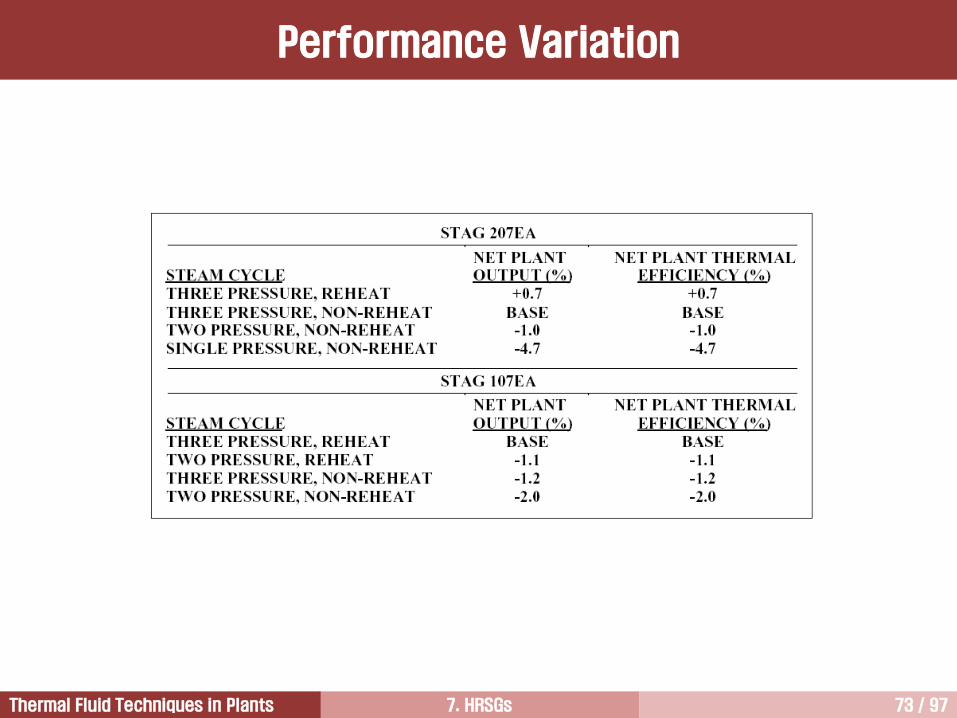
Performance Variation

7. HRSGs 74 / 97Thermal Fluid Techniques in Plants
568CTmax
HP IP
LP
(1-x)=16%
(1-x)=10%
T
s
Three Pressure
Reheat Cycle
Three Pressure
Non-reheat Cycle
Comparison of Cycle Performance
7. HRSGs 75 / 97Thermal Fluid Techniques in Plants
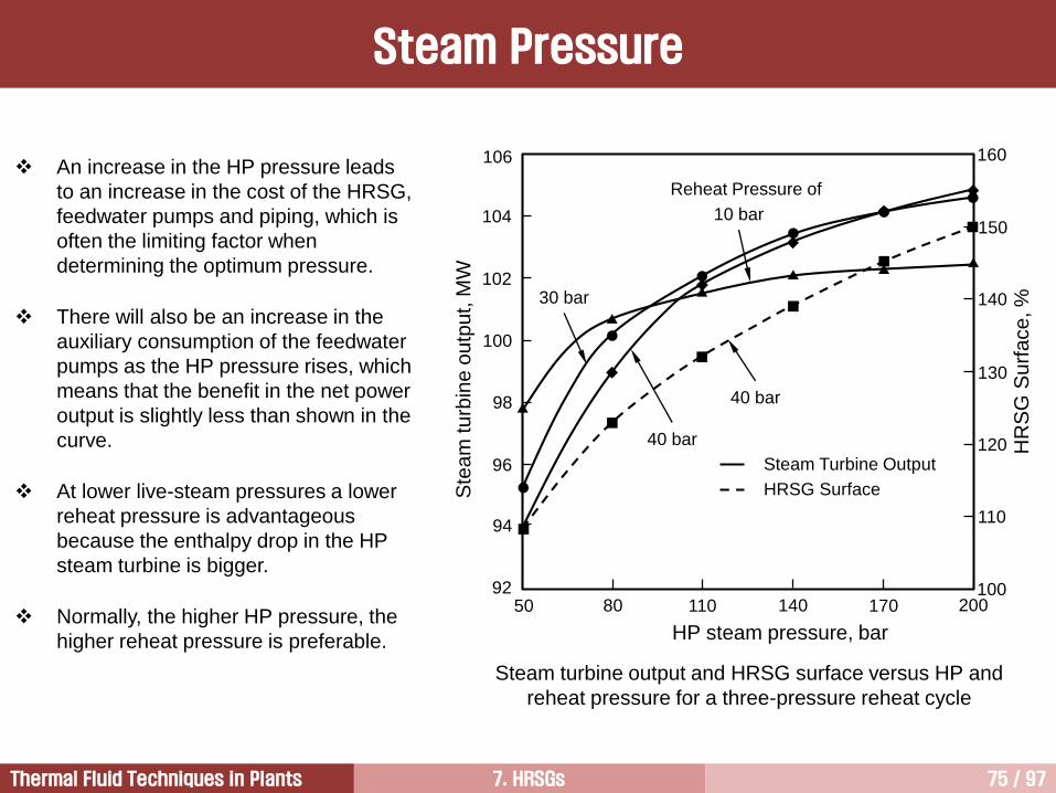
Steam turbine output and HRSG surface versus HP and
reheat pressure for a three-pressure reheat cycle
An increase in the HP pressure leads
to an increase in the cost of the HRSG,
feedwater pumps and piping, which is
often the limiting factor when
determining the optimum pressure.
There will also be an increase in the
auxiliary consumption of the feedwater
pumps as the HP pressure rises, which
means that the benefit in the net power
output is slightly less than shown in the
curve.
At lower live-steam pressures a lower
reheat pressure is advantageous
because the enthalpy drop in the HP
steam turbine is bigger.
Normally, the higher HP pressure, the
higher reheat pressure is preferable.
106
104
102
100
98
96
94
9250 80 110 140 170 200
100
110
120
130
140
150
160
Steam Turbine Output
HRSG Surface
HR
SG
Su
rfa
ce
, %
HP steam pressure, bar
Ste
am
tu
rbin
e o
utp
ut, M
W
40 bar
40 bar
10 bar
30 bar
Reheat Pressure of
Steam Pressure

7. HRSGs 76 / 97Thermal Fluid Techniques in Plants
Deaeration is the removal of noncondensable gases from the water or steam.
High oxygen content is in the water can cause erosion and corrosion of the components and piping that
contacting with water.
Typically, an oxygen content of less than 20 parts per billion (ppb) in the feedwater is recommended.
Deaeration must be done continuously because small leakages of air at flanges and pump seals cannot be
avoided.
Deaeration takes place when water is sprayed and heated (boiled), thereby releasing the dissolved gases.
Generally, the condensate is sprayed into the top of the deaerator.
Heating steam, fed into the lower part, rises and heats the water droplets to the saturation/boiling
temperature, releasing incondensable gases that are carried to the top of the deaerator and evacuated.
The feedwater tank is filled with saturated and deaerated water, and steam buffer above it prevents any
reabsorption of air.
Deaeration [1/2]

7. HRSGs 77 / 97Thermal Fluid Techniques in Plants
Deaeration will also partly take place in the condenser.
The steam turbine exhaust steam condensates and collects in the condenser hotwell, while the
noncondensable gases are extracted by means of evauation pump.
A steam cushion separates the water in the hotwell so that reabsorption of the air cannot take place.
Often, levels of deaeration in the condenser can be achieved that are comparable to those in the deaerator.
Therefore, the deaerator and feedwater tank can sometimes be eliminated from the cycle, and the
condensate is fed directly from the condenser into the HRSH drum.
In these cases the makeup water must be admitted to the cycle through the condenser.
Deaeration [2/2]

7. HRSGs 78 / 97Thermal Fluid Techniques in Plants
Deaerator [1/3]

7. HRSGs 79 / 97Thermal Fluid Techniques in Plants
보일러 급수계통은 급수에 포함되어 있는 용존산소와 이산화탄소에 의해서 가장 많이 부식된다.
용존산소는 이산화탄소에 비해서 5~10배 정도 부식성이 강하며, 급수온도가17˚C 증가할 때 마다 부식성이 2배 이상강해진다.
급수에 포함되어 있는 산소와 이산화탄소는 deaerator에서 제거된다.
Deaerator [2/3]

7. HRSGs 80 / 97Thermal Fluid Techniques in Plants
Deaerator [3/3]

7. HRSGs 81 / 97Thermal Fluid Techniques in Plants
GER-3936a
Cycle Diagram - S107H
7. HRSGs 82 / 97Thermal Fluid Techniques in Plants
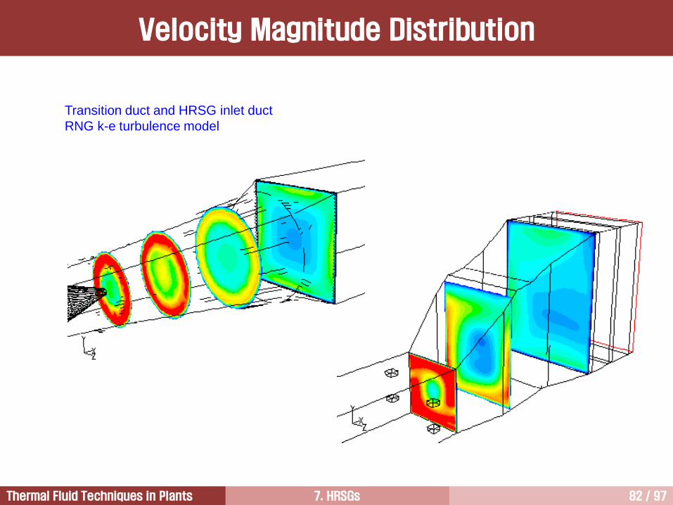
Transition duct and HRSG inlet duct
RNG k-e turbulence model
Velocity Magnitude Distribution

7. HRSGs 83 / 97Thermal Fluid Techniques in Plants
Side view
Plan view
Velocity Magnitude Distribution

7. HRSGs 84 / 97Thermal Fluid Techniques in Plants
Swirl vanes are located after the gas turbine as the
exhaust gas will tend to corkscrew up the duct with
some force particularly when the gas turbine is working
under off-design conditions.
Path Lines
7. HRSGs 85 / 97Thermal Fluid Techniques in Plants
starting
Moter
Generator
Gas
Turbine
Gas
Turbine
Exhaust duct
Flow
Correction
Device
Duct
Burner
HRSG
Air Inlet
Inlet duct
StackHPSection
IPSection
LPSection
Duct
Addtional
Air supply
Transition
Duct
제1도 가스터빈 및 배열회수보일러 개략도
A-A section
FCD
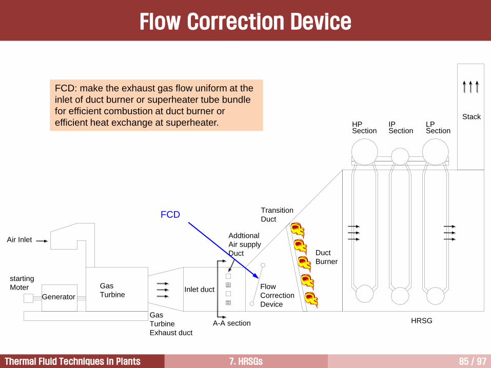
FCD: make the exhaust gas flow uniform at the
inlet of duct burner or superheater tube bundle
for efficient combustion at duct burner or
efficient heat exchange at superheater.
Flow Correction Device
7. HRSGs 86 / 97Thermal Fluid Techniques in Plants
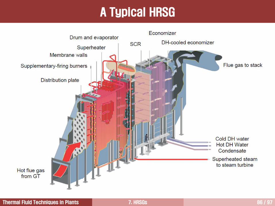
A Typical HRSG

7. HRSGs 87 / 97Thermal Fluid Techniques in Plants
Generally required velocity criteria (Top-
to-bottom and side-to-side)
Superheater: 50%
Duct burner: 15%
Configuration of a Typical FCD

7. HRSGs 88 / 97Thermal Fluid Techniques in Plants
Without FCD
With FCD
Grid System for the Design of FCD

7. HRSGs 89 / 97Thermal Fluid Techniques in Plants
W/O FCD
Uniform
Inlet Velocity
Non-uniform
Inlet Velocity
Uniform
Inlet Velocity
With FCD
With FCD
Uniform Inlet
Velocity Profile
Non-uniform Inlet
Velocity Profile
Investigation of Velocity magnitude

7. HRSGs 90 / 97Thermal Fluid Techniques in Plants
The most efficient power generation cycles are those with unfired HRSGs having modular pre-
engineered components.
These unfired steam cycles are the lowest in cost.
1. Combined cycle with unfired steam cycles
These are provided for customer specific applications.
These give an increased power, however, reduced thermal efficiency.
2. Combined cycle with supplementary-fired steam cycles
The most efficient cycles for cogeneration applications are those with fully-fired HRSGs.
These give maximum thermal energy output.
These are high in cost because of their water wall construction and need for field erection.
These may add to emission considerations.
3. Combined cycle with fully-fired steam cycles
Combined Cycle Performance

7. HRSGs 91 / 97Thermal Fluid Techniques in Plants
Investigation of HRSG Design Concepts3
HRSG Performance5
Introduction to HRSG1
Type of HRSGs (Horizontal vs. Vertical)2
Once-through HRSGs4
SCR6

7. HRSGs 92 / 97Thermal Fluid Techniques in Plants
HRSG with SCR [1/5]
SCR is a exhaust gas NOx reduction system that uses ammonia to react with NOx over a
catalyst that convert NOx into molecular nitrogen and water.
This system increases plant installation and operating cost.
Typically, the SCR catalyst operates under temperature range of 570F/300C and
750F/400C, therefore, the catalyst is typically installed within the high pressure
evaporator.
760F
O2=17%
895F
O2=16.4%
NOx=30 ppmv
CO=15 ppmv
680F
SC
R C
ata
lyst
CO
Ca
taly
st
395F
O2=16.4%
NOx=6 ppmv
CO=3 ppmv
Duct Burner

7. HRSGs 93 / 97Thermal Fluid Techniques in Plants
SCR Module
HRSG with SCR [2/5]

7. HRSGs 94 / 97Thermal Fluid Techniques in Plants
NOx level less than 9 ppmvd can be obtained at 15% oxygen for all combined cycle plants with selective
catalytic reduction (SCR) systems.
SCR is the most effective and proven technology to reduce NOx emissions, greater than 90%.
NOx contained in the gas turbine exhaust gas is converted into harmless molecular nitrogen and water on
the catalyst bed by the reaction with ammonia.
Conventional SCR technology operates in a narrow temperature range (288C-399C).
The equipment is comprised of segments stacked in the exhaust duct. Each segment has a honeycomb
pattern with passages aligned to the direction of the flow.
A catalyst such a vanadium pentoxide is deposited on the surface of the honeycomb.
For a GE turbine MS7001EA an SCR designed to remove 90% of the NOx has a volume of 175 m3 and
weights 111 tons.
The cost of the system, the efficiency penalty due to the pressure drop introduced by the catalyst, and the
potential for NH3 slip are the major disadvantages of this system.
A certain amount of ammonia, that is excess ammonia, may pass through the catalyst unreacted and
emitted into the atmosphere as “ammonia slip”.
Both NOx and ammonia are acutely toxic, and they contribute to fine particle formation, acidifying deposition.
In most cases, ammonia slip is currently limited by permit condition to either 5 or 10 ppm at 15% O2,
because ammonia is a hazardous material.
HRSG with SCR [3/5]
7. HRSGs 95 / 97Thermal Fluid Techniques in Plants
Ammonium hydroxide (수산화 암모늄) solution sprayed over a mesh containing titanium and vanadium
oxide catalysts reacts with the NOx to form nitrogen and water.
The reaction rate shows peak level at around 350C, and this temperature is appeared between the
evaporator and economizer sections of HRSG.
This systems are relatively expensive to install and maintain.
However, when the NOx emission should be controlled less than 10 ppm, this system can be used with the
combination of water injection.
Anhydrous ammonia (NH3) is the most cheap reagent.
Aqueous ammonia (NH4OH) is a safer to transport, handle and store than anhydrous ammonia. For these
reasons, many end-users and operators use it.
SCR systems are sensitive to fuels containing more than 1000 ppm sulfur.
Ammonia can lead to fouling of HRSG tubes downstream of the SCR if moderate quantities of sulfur are
present in the flue gas.
Ammonia and sulfur react to form ammonium bisulfate, a sticky substance that forms in the low temperature
section of HRSG (usually the economizer).
The deposited ammonium bisulfate is difficult to remove and can lead to a marked increase in pressure
drop across the HRSG.
HRSG with SCR [4/5]

7. HRSGs 96 / 97Thermal Fluid Techniques in Plants
SCONOX is a post-combustion catalytic system that removes both NOx and CO from the gas turbine
exhaust, but without ammonia injection.
The catalyst is platinum and the active NOx removal reagent is potassium carbonate.
Currently, SCONOX is used for only LM2500.
SCONOX is very sensitive to sulfur, even the small amount in pipeline natural gas.
The initial capital cost is three times the cost of SCR.
It has moving parts, reliability and performance degradation due to leakage may be significant issues.
Use of any exhaust gas treatment technology (SCR or SCONOX) results in pressure drop that reduces gas
turbine efficiency.
HRSG with SCR [5/5]

7. HRSGs 97 / 97Thermal Fluid Techniques in Plants
질의 및 응답
작성자: 이 병 은 (공학박사)작성일: 2016.02.15 (Ver.1)연락처: [email protected]
Mobile: 010-3122-2262저서: 실무 발전설비 열역학/증기터빈 열유체기술