Analysis of HRSG Cold-end Design Options for Best ... · due to accelerated corrosion or flow...
20
Analysis of HRSG Cold-end Design Options for Best Performance and Reliability Marco Dieleman M&N Power Solutions Ltd., Thailand ([email protected]) Milton Venetos, Wyatt Enterprises LLC, USA ([email protected]) Peter Pechtl, VTU Energy, Austria ([email protected]) Josef Petek, VTU Energy, Austria ([email protected])
Transcript of Analysis of HRSG Cold-end Design Options for Best ... · due to accelerated corrosion or flow...

Analysis of HRSG Cold-end Design Options
for Best Performance and Reliability
Marco Dieleman M&N Power Solutions Ltd.,
Thailand ([email protected])
Milton Venetos, Wyatt Enterprises LLC,
USA ([email protected])
Peter Pechtl, VTU Energy, Austria
Josef Petek, VTU Energy, Austria

Executive Summary
Maximizing the overall fuel efficiency of modern combined cycle power plants requires fine
tuning all of the main components in concert to reach a common optimum. Experience shows
that there exists a large potential for improvement in the so-called ‘cold-end’ of the HRSG
comprised of the condensate preheater section, the deaerator, and the first economizer sections of
the steam generator. Since these sections of the HRSG may also be subject to severe problems
due to accelerated corrosion or flow instabilities if operated under extreme conditions, caution
must be applied when looking for the optimal configuration.
The paper studies and compares various commercially available configurations, designs and
temperature control strategies of the HRSG cold-end. The study focuses on different
configuration options to prevent potential problems with the sulphuric acid dew point and
steaming in the low temperature economizer. It quantifies the impact of different fuel gas
compositions, condensate inlet temperatures, duct firing loads and modes of operation for the
deaerator on these key operational constraints. The study was performed using the EBSILON
Professional heat and mass balance software to construct detailed thermodynamic models for
both, design and off-design conditions in a typical 3-pressure level reheat HRSG. The study
incorporates the extensive experience the authors have in power plant design, optimization,
simulation and operations as well as available documentation, such as books, publications and
patents by HRSG vendors.
Introduction
An HRSG plays an important role in combined cycles, by utilizing the exhaust energy from the
gas turbine to raise steam, which is then supplied to the steam turbine. The HRSG’s performance
is therefore an important factor in the overall performance of the plant. It needs to contribute to
the overall plant efficiency while keeping in mind the reliability, flexibility, availability and
maintainability of the plant. This paper discusses the impact of the cold-end section of the HRSG
on those factors. The cold-end of an HRSG of is sometimes referred to as the “LP section” or
“back-end” as well. Various possible design configurations were considered for this paper and
their relative performance is compared.

Base Model
The layout of the combined cycle power plant was chosen to be 2 x 2 x 1 (2 gas turbines and
HRSGs, 1 steam turbine) with GE 9F.04 gas turbine type that was modelled with VTU’s Gas
Turbine Library software, developed for the EBSILON Professional power plant simulation
program (1). Figure 1 below shows the overall simulation model for one of the variants analyzed
in this study.
Figure 1: Overall plant simulation model
The HRSG configuration is horizontal with natural recirculation in the evaporators. The
condenser uses a mechanical draft wet cooling tower to remove the heat of condensation. Since
it was assumed that the two trains of the plant are always operated at the same load level if both
are running, the model was simplified by using stream multipliers/dividers on the connecting
streams between the GT/HRSG trains and the steam turbine and cooling system.
All EBSILON models used a base model that was derived from design information of a real
plant, but the low pressure section (feed water pre-heaters, low pressure (LP) evaporators, LP
economizers and a deaerator) was modified for the various cases that were studied. Table 1
below summarizes the key design parameters of the combined cycle power plant, and Figure 2
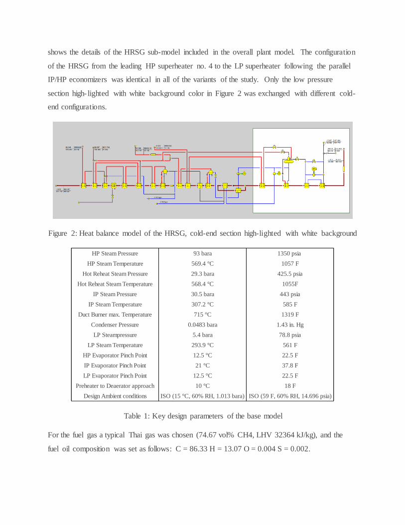
shows the details of the HRSG sub-model included in the overall plant model. The configuration
of the HRSG from the leading HP superheater no. 4 to the LP superheater following the parallel
IP/HP economizers was identical in all of the variants of the study. Only the low pressure
section high- lighted with white background color in Figure 2 was exchanged with different cold-
end configurations.
Figure 2: Heat balance model of the HRSG, cold-end section high-lighted with white background
Table 1: Key design parameters of the base model
For the fuel gas a typical Thai gas was chosen (74.67 vol% CH4, LHV 32364 kJ/kg), and the
fuel oil composition was set as follows: C = 86.33 H = 13.07 O = 0.004 S = 0.002.
HP Steam Pressure 93 bara 1350 psia
HP Steam Temperature 569.4 °C 1057 F
Hot Reheat Steam Pressure 29.3 bara 425.5 psia
Hot Reheat Steam Temperature 568.4 °C 1055F
IP Steam Pressure 30.5 bara 443 psia
IP Steam Temperature 307.2 °C 585 F
Duct Burner max. Temperature 715 °C 1319 F
Condenser Pressure 0.0483 bara 1.43 in. Hg
LP Steampressure 5.4 bara 78.8 psia
LP Steam Temperature 293.9 °C 561 F
HP Evaporator Pinch Point 12.5 °C 22.5 F
IP Evaporator Pinch Point 21 °C 37.8 F
LP Evaporator Pinch Point 12.5 °C 22.5 F
Preheater to Deaerator approach 10 °C 18 F
Design Ambient conditions ISO (15 °C, 60% RH, 1.013 bara) ISO (59 F, 60% RH, 14.696 psia)
Cold-End Configurations
Below is a description of the five different configurations of the HRSG back-end that were
considered:
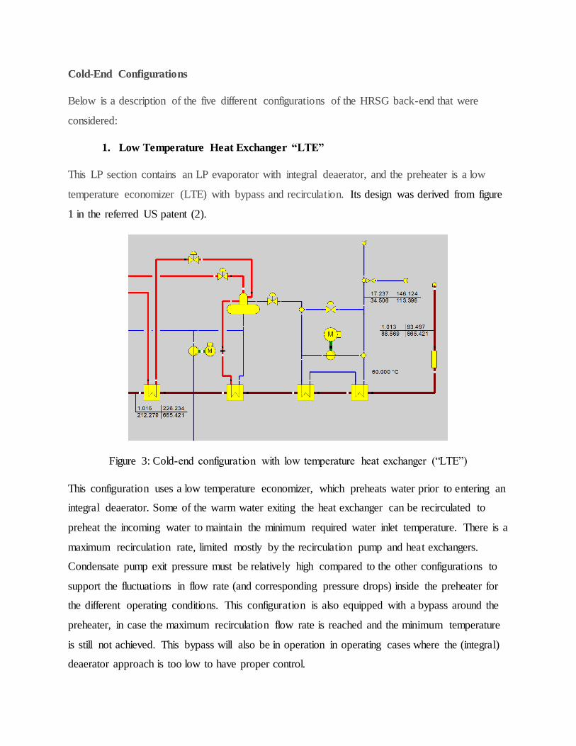
1. Low Temperature Heat Exchanger “LTE”
This LP section contains an LP evaporator with integral deaerator, and the preheater is a low
temperature economizer (LTE) with bypass and recirculation. Its design was derived from figure
1 in the referred US patent (2).
Figure 3: Cold-end configuration with low temperature heat exchanger (“LTE”)
This configuration uses a low temperature economizer, which preheats water prior to entering an
integral deaerator. Some of the warm water exiting the heat exchanger can be recirculated to
preheat the incoming water to maintain the minimum required water inlet temperature. There is a
maximum recirculation rate, limited mostly by the recirculation pump and heat exchangers.
Condensate pump exit pressure must be relatively high compared to the other configurations to
support the fluctuations in flow rate (and corresponding pressure drops) inside the preheater for
the different operating conditions. This configuration is also equipped with a bypass around the
preheater, in case the maximum recirculation flow rate is reached and the minimum temperature
is still not achieved. This bypass will also be in operation in operating cases where the (integral)
deaerator approach is too low to have proper control.

2. External Product/Feed Heat Exchanger (“PFHX”)
This LP section contains an LP evaporator with integral deaerator, and the preheater is
product/feed heat exchanger followed by a preheater. Its design was derived from figure 2 in the
referred US patent (2).
Figure 4: Cold-end configuration with external product/feed heat exchanger (“PFHX”)
The cold condensate enters the external product/feed heat exchanger at a rather low temperature
that results from mixing the main condensate flow at or slightly below the condensation
temperature and the return flow of HP feedwater from the fuel preheater. As this heat exchanger
is a water/water heat exchanger external to the HRSG, this fact causes no problems. In order to
produce the required minimum inlet temperature into the preheater at the cold end of the HRSG,
the exit stream of this preheater is returned to the product/feed heat exchanger. A bypass
upstream of the product/feed heat exchanger allows for controlling the preheater inlet
temperature. This bypass stream is mixed with the hot-side outlet of the product feed heat
exchanger. If the resulting mixing temperature is above the lower limit for water temperature
entering the HRSG, the resulting flow passes through another preheater section. In case the inlet
temperature is too low, the second preheater may be bypassed completely. This design doesn’t
require an additional pump, as both bypass lines operate with positive pressure differences.

3. External Deaerator and Product/Feed Heat Exchanger “EXTDA + PFHX”
This design contains an LP evaporator with separate deaerator, and the preheating section
consists of an external product/feed heat exchanger followed by the economizers at the three
HRSG pressure levels.
Figure 5: Cold-end configuration with external deaerator and product/feed heat exchanger
(“EXTDA + PFHX”)
In this configuration, the external product feed heat exchanger is linked to the deaerator
operating just above atmospheric pressure. The controlling element for establishing the required
water inlet temperature into the HRSG is the partial bypass of the hot side of the P/F heat
exchanger which raises the economizer inlet temperature with deaerator outlet water at the
expense of lowering the deaerator inlet temperature. In order to maintain a required level of sub-
cooling of the inlet stream into the deaerator, the product/feed heat exchanger may also be
bypassed on the cold side. If required, the deaerator pressure could be raised to increase the
HRSG inlet temperature further (such as in case of operation with fuel oil). The LP, IP and HP
circuits are separated once leaving the deaerator. This configuration also doesn’t require an
additional recirculation pump.

4. Product/Feed Heat Exchanger with two parallel LT Economizers “ PFHX +
2LTE”
This LP section design consists of two preheaters located side by side in the flue gas stream, with
feed water flowing through the external product/feed heat exchanger prior to entering the first
preheater. Two further preheaters follow which may be used, if the respective inlet temperature
limit is not violated. This design was derived from figure 5 in the referred US patent (2).
Figure 6: Cold-end configuration with product/feed heat exchanger and two parallel LT
Economizers (“PFHX + 2LTE”)
Under off-design conditions a bypass around the external heat exchanger is used in case the inlet
temperature to the HRSG would drop too low (thereby preheating less water in the same heat
exchanger, achieving a higher temperature). If that is insufficient or if that causes the inlet
temperature to the second preheater stage to drop too low, additional bypass of the final stage of
the preheater might be required. This bypass will also be in operation in operating cases where
the integral deaerator approach is too low to have accurate control of the deaerator saturation
conditions. No additional pump is required.
5. External deaerator with Recirculation“ RECIRC EXTDA”
This LP section comprises of an external (vacuum) deaerator followed by a recirculation heater
for deaerator water, followed by various economizers.

Figure 7: Cold-end configuration with external recirculating deaerator (“RECIRC EXTDA”)
This configuration uses a vacuum pressure deaerator operated at the saturation pressure
corresponding to meet minimum feed water heater inlet temperature. The LP, IP and HP circuits
are separated once leaving the deaerator. One additional heat exchanger is added to reduce the
stack temperature and to heat water to aid in the deaeration. The circulation flow in this heat
exchanger is varied to minimize the steam requirement for deaeration. The recirculation flow rate
could be varied, if desired, to achieve lower stack temperatures and better heat rates, but is not
required for the purpose feedwater temperature control. However, for the purpose of this study it
was assumed the flow rate can be varied.
Study Approach
To ensure this study properly compares the different configurations, care was taken to apply the
same design conditions and limits, such as minimum HRSG water inlet temperature, pinch
points, maximum duct firing temperature, etc. in all configurations.
The cold-end of the HRSG has to be designed to handle several potential problems. In particular,
these involve sulphuric acid condensation, fatigue stress, erosion due to steaming, carbonic acid
and other so called Flow Accelerated Corrosion (FAC) problems. Temperature control,
deaeration, maintaining reducing environments and pH control all play a role in this.

In order to prevent condensation of sulphuric and other acid gases, the cold-end of the HRSG
must be properly designed to ensure metal temperatures stay above the appropriate dew points.
Of the sulphuric gases which could cause corrosion of HRSGs, the one with the lowest dew point
is typically SO3 (H2SO4 in liquid form).
This empirical correlation can be used to estimate the sulphuric dew point:
Tdew, H2SO4 = 1000/[2.276 - 0.0294 ln(p H2O) - 0.0858 ln(p SO3) + 0.0062 ln(p H2O p SO3)];
with P in atm, T in K (3)
But this requires an assumption on SO2 to SO3 conversion, typically up to 5-6% (4, 5). The
actual conversion rate will be dependent on the amount of excess air and the residence time.
Some additional H2SO4 can come from SO2 to SO3 conversion if SCR is present. And finally,
some addition H2SO4 can form in the following reaction:
NO2 + SO2 + H2O = H2SO4 +NO
Nitric acid usually has a lower dew point than H2SO4 and is therefore less restrictive.
4NO2 + 2H2O + O2 = 4HNO3
Tdew, HNO3 =Td NO2 = 1000/(3.664 - 0.1446*ln(H2O /100*760) -
0.0827*ln(NO2/1000000*760) +0.00756*ln(H2O /100*760)*ln(NO2/1000000*760)) – 273;
with H2O in vol%, NO2 in ppmv (6)
Similarly the sulphurous dew point is also less restrictive:
Tdew, H2SO3 = 1000/{3.9526 - 0.1863*ln(PH2O) + 0.000867*ln(PSO2) -
0.00091*ln(PH2O*PSO2)}
with P in inHg, T in K (7)
Once the dew point and the surface temperatures are known (or estimated), gas temperature does
have some impact on corrosion too, namely on the acid deposit rates of the acid film. The impact
might be counter-intuitive: the higher the stack temperature, the faster the deposit rate due to
higher mass and energy transfer rates (8).
Finally, the water dew point is a function of the partial pressure of H2O only.

For typical exhaust gas compositions in gas turbine fired power plants, the sulphuric dew point is
the most restrictive, if Sulphur is present in the fuel gas or oil. In the absence of sulphuric gases
the water dew point in the flue gas must be taken into consideration.
The design of the HRSG should allow for control of the surface temperature of the coldest heat
exchanger tubes to ensure that they remain above the most restrictive dew point temperature. The
coldest temperature is at the surface of the coldest tubes. Due to the larger interior heat transfer
coefficient (liquid phase) compared to the exterior heat transfer coefficient (gas phase), the
surface temperature is governed most by the water inlet temperature. Therefor the water inlet
temperature must be maintained above the most restrictive dew point. This is achieved either by
changing deaerator pressure (configuration 5), or by providing a preheater bypass/recirculation
(in the other 4 configurations).
The main purpose of the deaerator is to remove Dissolved Oxygen (DO) and other unwanted
gases, such as CO2, from the water stream. Leaving them in would cause or enhance corrosion
which can occur even at relatively low temperatures. Additional purposes of the deaerator
include preheating the condensate and providing the necessary Net Positive Suction Head
(NPSH) to the Boiler Feed Pumps.
Unwanted gases can enter through leaks in condensate pumps or hotwell, which can for example
be eliminated with welding. But, air entering along with gland seal steam must be removed by
venting. Makeup water and process condensate return from cogeneration plants often contain
dissolved gases as well.
There are also potential problems on the water side of the tubes. According to (9) Flow
Accelerated Corrosion (FAC) is a progressive form of water-side metal wastage that strips away
metal from the wetted surfaces of pressure parts. Pressure parts will thin if FAC is occurring, and
failures will result if it is allowed to continue. Often two types of FAC are considered separately,
single phase and 2-phase FAC.
The phenomenon is most likely to attack pressure parts under the following conditions:
Reducing environment (zero oxygen, possible excess scavenger).
Extremely low DO content (at or near zero).
Low boiler-water pH (less than 9.2).

High water-side velocities.
Water temperatures between 110C and 249 C / 230F and 480F.
Pressure parts made of carbon steel.
Practically this means that the cold-end section of the HRSG is most susceptible to this problem,
and to some degree the IP section.
Iron can dissolve in water Fe + 2H2O Fe(OH)2 + 2H+ +2e-, and iron hydroxide may form:
2 Fe + O2 + 2 H2O-> 2 Fe(OH)2 (10)
This can then react further with O2:
4 Fe(OH)2 + O2 +2 H2O -> 4 Fe(OH)3
Reactivity increases with temperature. It can also react further to form magnetite (Fe3O4), which
has the ability to form a protective layer:
3 Fe(OH)2 -> Fe3O4 + 2 H2O + 2 H+ + 2e-
This protective layer may not form when O2 is present and the water is mildly alkaline (pH 7-
9.2). Magnetite, under normal circumstances, allows only limited amounts of the iron to dissolve
in water (up to 5ppb), but when FAC occurs, often due to a reduction reaction (such as hydrogen
presence in the water) it can be much higher, quickly leading to thinning tubes. (9).
Two-phase FAC (steaming) cannot be influenced by Oxygen concentration, this is usually done
by way of local pH control (~9.8). (11). While outside the scope of this paper, any material
removed by way of FAC will contribute to Under-Deposit Corrosion, most likely in the HP
evaporator.
CO2 can lead to carbonic acid formation:
CO2 + H2O H2CO3
This leads to corrosion and increases acidity (lowers pH). Corrosion can also be reduced by
maintaining a high enough pH, but that has an impact on the ability to form magnetite, as
mentioned earlier. Chemically bound CO2 cannot be removed by deaeration so pH is kept
relatively high to avoid the formation of carbonic acid. This pH cannot be much above 9.8, since

caustic corrosion would cause the protective magnetite layer to be dissolved (9). It should also
not drop too much lower than 9.2 either to prevent acidic corrosion.
These and other undesired chemical reactions force the removal of CO2 and O2. The deaerator
achieves this by spraying the cold or preheated condensate water into the top of the deaerator and
steam is added to the deaerator to heat the water via direct contact up to the saturation point.
Spraying to reduce surface tension and heating to reduce solubility of the gases both help to
release unwanted gases from the deaerator. A second stage of removal can be achieved by using
scrubbers, such as trays or by releasing steam at the bottom of the water vessel (12). The steam
supply in an HRSG will mostly come from the LP evaporator, but additional pegging steam can
be taken from IP or even HP letdowns in case the LP evaporator cannot produce enough steam. It
is obvious then that the deaerator must be operated at a pressure below or at LP evaporator
pressure. Some heating can be done in preheaters, so that less steam production is required. But
since some steam is always required, the inlet temperature to the deaerator should maintain a
minimum approach to prevent deaerator steam flow control issues. In case of preheaters, it is
therefore often required to have a potential bypass around the preheater for part load conditions
where the preheater exit temperature would approach the deaerator operating temperature too
closely.
In addition to controlling the steam flow, the deaerator pressure can be controlled, too. If the
preheaters don’t provide a lot of energy to the deaerator, lowering the pressure in the deaerator
reduces the steam requirement. Of course there is a minimum pressure that must be maintained
in the LP evaporator, dictated by the LP admission pressure into the LP steam turbine inlet.
Furthermore, the maximum deaerator pressure is also limited once the material of the boiler feed
pump is chosen. The temperature in the deaerator often may thus not be allowed to exceed 150C.
The benefit of having an integral deaerator versus a separate deaerator lies in investment cost
savings. But a disadvantage is that the deaerator pressure and LP evaporator pressure cannot be
independently controlled and optimized. Furthermore, independent pH control for the HP and IP
and LP sections is more difficult, if the LP drum has an integral deaerator.
Another advantage of having a recirculation system is apparent during start up. Most feedwater
heaters will contain water during shutdown and will initially heat up, but without flowing, since

steam production has not started yet. By the time steam production starts, cold water would be
added to the already warm water inside the feed water heaters. Such cold water being added to
warm tubes would lead to shock and the resulting thermal fatigue, which in turn leads to cracks.
Furthermore, it can damage the protective magnetite layer (9). Recirculating warm water prior to
steam production and mixing it with the cold condensate prior to entering the preheater during
startup operation is one way to prevent such problems. Furthermore, a recirculation system is
useful to maintain minimum flow in the preheater under low load conditions when steaming in
the preheaters may occur or when tube-to-tube temperature differences might get too high (13).
Another way to prevent steaming is to ensure that he condensate pump provides sufficient
pressures that are much higher than the deaerator or LP evaporator pressures.
It is obvious from the previous discussions that there are several optimization points within the
cold-end section of the HRSG, and also several restrictions.
Optimization points include location of deaerator, preheater size, deaerator pressure, or LP
evaporator pressure. Some of the optimizations need to be made at the design point, while others
require adjustments derived from evaluation a range of operating conditions / points.
Restrictions such as: minimum feed water heater inlet temperature and minimum deaerator
approach temperature need to be considered. For this study, we assumed the following
restrictions related to the cold-end design:
minimum feed water heater inlet temperature = 60C / 140F
minimum deaerator approach temperature = 10C / 18F
SO2 to SO3 conversion rate = 5%
To compare the performance of the various HRSGs, one cannot simply compare the HRSG
performance by itself. It is after all possible to improve the HRSG performance without
improving plant performance. One example of this would be that a lower LP evaporator pressure
might reduce stack temperatures and appear to improve performance, but lower LP evaporator
pressures might not benefit the steam turbine as much as a higher LP evaporator pressure would.
For each configuration studied, several runs were performed to investigate their impact on the
HRSG cold-end parameters

a. Base case (“ISO”), with ISO ambient conditions, no duct firing, all HRSGs in operation
b. Off-design (“Duct Fire”), 35C ambient. temperature, 90% rel. humidity and maximum duct
firing
c. Off-design (“Fuel Oil”) as the higher sulphur case (fuel oil fired GT, w/o duct burner) at ISO
d. Off-design (“1 GT off”) as 1GT/HRSG outage mode under ISO conditions with maximum
duct firing
Results
While the achievable net electrical output is approximately the same in all configurations (see
Table 3 below), the heat rate for those configurations with external product/feed heat exchanger
and integral deaerator (i.e. configurations 2 and 4) show significantly higher heat rates in the oil-
fired case.
Figure 8: Comparison of overall plant net heat rate for the cold-end configurations for four
operating cases: base load at ISO (1), 35C ambient temperature with maximum duct firing (2),
base load operation with fuel oil (3), and outage mode operation with 1 GT/HRSG train off (4).

Table 3: Summary of heat balance results for plant configurations 1 to 5
Parameter UOM ISO Duct Fire Fuel Oil 1GT off ISO Duct Fire Fuel Oil 1GT off ISO Duct Fire Fuel Oil 1GT off ISO Duct Fire Fuel Oil 1GT off ISO Duct Fire Fuel Oil 1GT off
Plant Net Heat Rate kJ/kWh 6226 6710 6392 6546 6223 6715 6503 6622 6249 6740 6435 6568 6223 6716 6533 6589 6218 6709 6401 6542
Plant Net Power MW 828.5 804.8 769.1 458.8 828.9 804.3 756.0 453.4 825.4 800.6 764.0 457.0 828.8 804.2 752.5 455.9 829.5 803.2 768.0 458.3
Auxiliary Power MW 15.6 17.8 12.6 12.9 15.2 17.4 11.4 12.5 14.8 16.9 11.2 12.3 15.2 17.4 11.5 12.5 15.3 17.2 11.8 12.7
HP Steam Production kg/sec 166.4 231.6 155.8 124.1 166.4 231.7 156.5 124.2 166.3 230.4 156.0 123.6 166.4 231.7 156.8 124.3 167.1 230.8 156.6 123.9
HP Steam Pressure bara 93.0 127.4 86.6 71.0 93.0 127.5 86.7 70.9 93.0 126.8 86.7 70.7 93.0 127.5 86.7 71.1 93.0 126.4 86.6 70.6
HP Steam Temperature °C 569.4 569.4 555.9 569.4 569.4 569.4 555.6 569.4 569.4 569.4 555.8 569.4 569.4 569.4 555.7 569.4 569.4 569.4 555.9 569.4
HRH Steam Flow kg/sec 183.9 243.3 174.1 130.5 183.9 243.4 172.0 128.3 184.5 241.8 175.0 129.9 183.9 243.4 168.5 130.6 184.2 241.2 174.7 129.9
HRH Steam Pressure bara 29.3 38.6 27.5 20.8 29.3 38.6 27.1 20.4 29.3 38.3 27.5 20.6 29.3 38.6 26.5 20.8 29.3 38.2 27.5 20.7
HRH Steam Temperature °C 568.4 567.8 554.2 567.8 568.4 567.8 554.5 567.8 568.4 567.8 554.1 567.8 568.4 567.8 554.2 567.8 568.4 567.8 554.1 567.8
IP Steam Production kg/sec 8.8 5.8 9.1 6.4 8.8 5.8 9.4 6.5 9.1 5.7 9.5 6.4 8.8 5.8 9.4 6.4 8.6 5.2 9.0 6.0
IP Steam Pressure bara 30.5 40.0 28.7 23.9 30.5 40.0 28.2 23.4 30.5 39.7 28.7 23.7 30.5 40.0 27.6 23.8 30.5 39.6 28.7 23.7
IP Steam Temperature °C 307.2 338.7 300.9 309.8 307.2 338.7 300.3 309.4 307.2 339.6 300.9 310.2 307.2 338.7 299.9 309.8 307.2 339.8 300.7 310.1
LP Steam Production kg/sec 25.6 18.0 21.1 6.0 25.5 15.7 0.0 0.0 19.3 13.0 9.4 4.0 25.5 15.6 0.0 0.0 28.2 20.9 18.3 7.2
LP Steam Pressure bara 5.4 6.7 5.0 3.5 5.4 6.7 4.4 3.3 5.4 6.8 4.9 3.6 5.4 6.7 4.3 3.4 5.4 6.7 4.9 3.5
LP Steam Temperature °C 293.9 327.9 296.5 310.3 293.9 332.5 146.9 136.8 293.9 328.8 309.0 311.7 293.9 332.7 146.1 137.4 293.9 325.0 303.9 308.6
Condenser Pressure mbar 48.3 144.7 44.7 32.7 48.3 143.6 39.5 31.1 48.3 144.9 43.4 32.9 48.3 143.5 38.7 31.5 48.3 143.3 43.6 32.4
Preheater Recirc Flow kg/sec 28.8 6.8 165.0 73.7 0.0 0.0 0.0 0.0 0.0 0.0 0.0 0.0 0.0 0.0 0.0 0.0 79.1 25.5 160.0 160.0
Preheater Bypass Flow kg/sec 0.0 0.0 0.0 0.0 0.0 0.0 83.5 0.0 0.0 0.0 99.0 0.0 0.0 0.0 0.0 29.4 0.0 0.0 0.0 0.0
Deaerator Pressure bara 6.25 7.10 5.64 3.82 6.25 6.97 4.37 3.30 1.03 1.03 1.14 1.04 6.25 6.96 4.29 3.36 0.20 0.20 1.01 0.20
PH Inlet Temperature °C 60.0 60.0 99.9 60.0 60.0 69.4 100.0 61.1 60.0 74.0 100.0 59.7 60.0 69.0 bypass 60.0 60.0 60.0 100.0 60.0
PH2 Inlet Temperature °C - - - - 69.6 77.5 bypass bypass - - - - 69.6 77.0 bypass 71.9 - - - -
PH3 Inlet Temperature °C - - - - - - - - - - - - 100.0 96.0 bypass bypass - - - -
Stack temperature °C 88.6 84.6 105.8 71.6 88.0 88.6 152.7 105.5 99.5 98.2 126.8 81.8 88.0 88.8 160.5 95.1 82.6 81.4 109.8 68.0
Sulphuric Dew Point °C 0.0 0.0 89.5 0.0 0.0 0.0 89.5 0.0 0.0 0.0 89.5 0.0 0.0 0.0 89.5 0.0 0.0 0.0 89.5 0.0
Nox Dew Point °C 11.0 13.5 8.3 11.7 11.0 13.5 8.3 11.7 11.0 13.5 8.3 11.7 11.0 13.5 8.3 11.7 11.0 13.5 8.3 11.7
Sulphurous Dew Point °C -0.7 0.2 0.1 0.2 -0.7 0.2 0.1 0.2 -0.7 0.2 0.1 0.2 -0.7 0.2 0.1 0.2 -0.7 0.2 0.1 0.2
Water Dew Point °C 42.8 51.7 33.9 45.2 42.8 51.7 33.9 45.2 42.8 51.7 33.9 45.2 42.8 51.7 33.9 45.3 42.8 51.7 33.9 45.2
Total Surface Area m²
LTE PFHX EXTDA + PFHX PFHX + 2LTE RECIRC EXTDA
Configuration 1 Configuration2 Configuration 3 Configuration 4 Configuration 5
230,196 224,964 248,987 223,651 272,166

Figure 9: Comparison of total HX surface area for the five configurations
Conclusions
The pros and cons of the various configurations are summarized in Table 4 below.
Table 4: Qualitative assessment of the cold-end configurations under evaluation
Criterion/Feature LTE PFHX EXTDA + PFHX PFHX + 2LTE RECIRC EXTDA
Heat Rate (average) best worst average average best
Heat Rate for at design conditions average average worst average best
Power (average) highest lowest average second lowest second highest
Power at design conditions average average lowest average highest
Stack Temperature (average) second lowest highest average Second Highest lowest
Deaerator type integrated integrated external, ~ 1 atm integrated external, vacuum
Deaerator upstream of gas/H2O HX no no yes no yes
HP and IP drum fed from LP drum yes yes no yes no
Feed Water Inlet Temperature
Control
recirculation,
followed by bypass
if needed
external HX
bypass, followed by
preheater bypass if
needed
external HX bypass
+ deaerator
pressure
external HX
bypass, followed by
preheater bypass if
needed
deaerator pressure
Heat Exchange Area average smallest second largest smallest largest
Number of Drums (HP,IP, LP,DA) 3: HP, IP, LP/DA 3: HP, IP, LP/DA 4: HP, IP, LP, DA 3: HP, IP, LP/DA 4: HP, IP, LP, DA
Pumps HP, IP, Recirc HP, IP HP, IP, LP HP, IP HP, IP, LP, Recirc

Performance differences are obviously best expressed by looking at power and heat rate
differences. But, other factors should be considered too. For example, the location of the
deaerator impacts where the unwanted dissolved gases are removed and the effect of corrosion
will be impacted by the location of the deaerator. If an HP and IP steam water/system is fed by
the LP drum then this increases the likelihood of corrosion deposit carry-over from the LP
system to the HP/IP systems, which could increase their vulnerability to Under-Deposit
Corrosion. Furthermore, having the LP, IP and HP systems separated would make it easier to
independently regulate the chemical composition of the water in the different sections to combat
the various corrosion impacts, each of which of have different temperature dependencies.
Feedwater temperature control for the water stream entering the HRSG will determine in part the
ability to decrease stack temperature (recirculation configurations out-perform bypass
configurations in this aspect).
Parameters such as heat exchanger area, number of drums and number of pumps obviously have
an impact on the cost. And parasitic loads will generally be higher when recirculation pumps are
used.
Performance (power and heat rate) is nearly the same for all configurations, at least for the most
basic operating points. But for the less common operating points, such as fuel oil operation and a
GT outage mode there are substantial differences. There is no configuration that is consistently
the best option for power heat rate, capital cost and ease of operation.
Due to the differences in performance between recirculation options vs. external heat exchanger
options, particularly for less common operating points, and due to the differences in investment
cost, it is likely that the best configuration is dependent on the amount of running hours the plant
is expected to spend in the less common operation points, to see if the additional cost is worthy
investment.
Compared to the recirculation configurations (configuration 1 and 5), the external heat exchanger
configurations (such as 2 and 4) reduce the overall heat exchanger surface area, and they
eliminate a recirculation pump and its parasitic power requirement. This reduces capital and
O&M costs and improves reliability. But as shown, the heat rate can be worse depending on the
operating conditions.

In order to identify the optimal configuration for a given set of operating points, a flexible
modeling software will be required which can handle all configurations and all off-design
scenarios the plant is likely to encounter.
Acknowledgement
The authors wish to acknowledge and thank Mr. Yuri Rechtman of Nooter/Eriksen for providing
the HRSG design data that the EBSILON models in this paper were based on.
References
1. EBSILON®Professional Software manual, www.ebsilon.com
2. Rechtman, [2003], US patent 6508206B1.
3. Verhoff, F.H. and J.T. Banchero, 1977, Chemical Engineering Progress, Vol. 70, p. 71.
4. IAPWS, 2008, Certified Research Need 23 –Dew Point for Flue Gas of Power-Plant
Exhaust Available at: http://www.iapws.org/icrn/ICRN23.pdf [Accessed Jun 2015].
5. Ganapathy, V., 1989, Cold end corrosion: causes and cures, Hydrocarbon Processing,
January.
6. Perry R.H. and Chilton C.H., 1973, Chemical Engineers Handbook 5th edition McGraw
Hill, New York.
7. Yen Hsiung Kiang, 1981, Predicting dew points of acid gasses, Chemical Engineering
Feb, 9.
8. Huijbrechts W.M.M. and Leferink, R., 2004, Latest advances in the understanding of acid
dew point corrosion: corrosion and stress corrosion cracking combustion gas
condensates, Anti-Corrosion Methods and Materials, Vol. 51, 3, p. 173-188, revision
2013.
9. Cotton, I.J. and Obermaier, J., 2006, How to prevent corrosion and deposition, and
maintain steam purity, in combined-cycle/cogen plants, Combined Cycle Journal Online,
q3. Available at: http://www.ccj-online.com/3q-2006/steam-purity/ [Accessed June 2015]
10. GE Water Handbook of Industrial Water Treatment- Chapter 11 Pre-Boiler and Boiler
corrosion. Available at GE Water website
http://www.gewater.com/handbook/boiler_water_systems/ch_11_preboiler.jsp [Accessed
June 2015].

11. Dooley, B. and Anderson, B., 2009, Assessments of HRSGs - Trends in Cycle Chemistry
and Thermal Transient Performance. Available at: http://www.ppchem.net/ab-
pdfs/2009/abstracts-03-2009.pdf [Accessed June 2015].
12. American Boiler Manufacturers Association (ABMA), 2011, a discussion of boiler
deaerator technologies in use in today’s marketplace, whitepaper of deaerator
manufacturers product/market group of ABMA.
13. Pearson, M.J. and Anderson, R., 2005, Measurement of Damaging Thermal Transients on
F Class Horizontal HRSGs. In: ETD International Seminar on Cyclic Operation of Heat
Recovery Steam Generators (HRSGs), London, United Kingdom 24 June 2005.