
53D4B5424F48B67646B348E6C9FD7FA
22
408 7 Cylindrical Tubular Members 7.1 GENERAL REMARKS The design of square and rectangular tubular sections as flexural and com- pression members is discussed in Chaps. 3 to 6. This chapter deals with the strength of cylindrical tubular members and the design practice for such mem- bers used as either flexural or compression members. Thin-walled cylindrical tubular members are economical sections for com- pression and torsional members because of their large ratio of radius of gy- ration to area, the same radius of gyration in all directions, and the large torsional rigidity. In the past, the structural efficiency of such tubular members has been recognized in building construction. A comparison made by Wolford on the design loads for round and square tubing and hot-rolled steel angles used as columns indicates that for the same size and weight, round tubing will carry approximately 2 and 1 times the column load of hot-rolled angles 1 1 – – 2 2 when the column length is equal to 36 and 24 times the size of section, respectively. 7.1 7.2 TYPES OF CYLINDRICAL TUBES The buckling behavior of cylindrical tubes, which will be discussed later, is considerably affected by the shape of the stress–strain curve of the material, the geometric imperfections such as out of roundness, and the residual stress. It would therefore be convenient to classify tubular members on the basis of their buckling behavior. In general, cylindrical tubes may be grouped as (1) manufactured tubes and (2) fabricated tubes. 7.2 Manufactured tubes are produced by piercing, forming and welding, cupping, extruding, or other methods in a plant. Fab- ricated tubes are produced from plates by riveting, bolting, or welding in an ordinary structural fabrication shop. Since fabricated tubes usually have more severe geometric imperfections, the local buckling strength of such tubes may be considerably below that of manufactured tubes. Manufactured structural steel tubes include the following three types: 1. Seamless tubes 2. Welded tubes 3. Cold-expanded or cold-worked tubes
-
Upload
darko-nikolovski -
Category
Documents
-
view
214 -
download
1
description
N
Transcript of 53D4B5424F48B67646B348E6C9FD7FA

408
7 Cylindrical Tubular Members
7.1 GENERAL REMARKS
The design of square and rectangular tubular sections as flexural and com-pression members is discussed in Chaps. 3 to 6. This chapter deals with thestrength of cylindrical tubular members and the design practice for such mem-bers used as either flexural or compression members.
Thin-walled cylindrical tubular members are economical sections for com-pression and torsional members because of their large ratio of radius of gy-ration to area, the same radius of gyration in all directions, and the largetorsional rigidity. In the past, the structural efficiency of such tubular membershas been recognized in building construction. A comparison made by Wolfordon the design loads for round and square tubing and hot-rolled steel anglesused as columns indicates that for the same size and weight, round tubingwill carry approximately 2 and 1 times the column load of hot-rolled angles1 1– –2 2
when the column length is equal to 36 and 24 times the size of section,respectively.7.1
7.2 TYPES OF CYLINDRICAL TUBES
The buckling behavior of cylindrical tubes, which will be discussed later, isconsiderably affected by the shape of the stress–strain curve of the material,the geometric imperfections such as out of roundness, and the residual stress.It would therefore be convenient to classify tubular members on the basis oftheir buckling behavior.
In general, cylindrical tubes may be grouped as (1) manufactured tubesand (2) fabricated tubes.7.2 Manufactured tubes are produced by piercing,forming and welding, cupping, extruding, or other methods in a plant. Fab-ricated tubes are produced from plates by riveting, bolting, or welding in anordinary structural fabrication shop. Since fabricated tubes usually have moresevere geometric imperfections, the local buckling strength of such tubes maybe considerably below that of manufactured tubes.
Manufactured structural steel tubes include the following three types:
1. Seamless tubes2. Welded tubes3. Cold-expanded or cold-worked tubes

7.3 FLEXURAL COLUMN BUCKLING 409
For the seamless tubes, the stress–strain curve is affected by the residualstress resulting from cooling of the tubes. The proportional limit of a full-sized tube is usually about 75% of the yield point. This type of tube has auniform property across the cross section.
Welded tubes produced by cold forming and welding steel sheets or plateshave gradual-yielding stress–strain curves, as shown in Fig. 2.2 due to theBauschinger effect and the residual stresses resulting from the manufacturingprocess. The proportional limit of electric-resistance welded tubes may be aslow as 50% of the yield point.
Cold-worked tubes also have this type of gradual yielding because of theBauschinger effect and the cold work of forming.
7.3 FLEXURAL COLUMN BUCKLING
The basic column formulas for elastic and inelastic buckling discussed inChap. 5 [Eqs. (5.3a) and (5.7a) are usually applicable to tubular compressionmembers having a proportional limit of no less than 70% of the yield point.For electric-resistance welded tubes having a relatively low proportional limit,Wolford and Rebholz recommended the following formulas on the basis oftheir tests of carbon steel tubes with yield strengths of 45 and 55 ksi (310and 379 MPa):7.3
1. For KL/r � 2�3� E/F ,y
2 F KLy� � F 1 � (7.1)� � ��T y 2�� E r3�3
2. For KL/r � 2�3� E/F ,y
2� E� � (7.2)e 2(KL/r)
where Fy, E, K, and L are as defined in Chap. 5. The radius of gyration r ofcylindrical tubes can be computed as
2 2�D � D Ro ir � � (7.3)
4 �2
where Do � outside diameterDi � inside diameterR � mean radius of tube

410 CYLINDRICAL TUBULAR MEMBERS
Figure 7.1 Test data for column buckling of axially loaded cylndrical tubes.3.84
The correlation between the test results and Eqs. (5.3), (5.7), (7.1), and(7.2) is shown in Fig. 7.1.3.84,7.4,7.5 Also shown in this figure are the test datareported by Zaric.7.6
Because cylindrical tubes are now commonly used in offshore structures,extensive analytical and experimental studies of the strength of tubular mem-bers have recently been made by numerous investigators throughout theworld.7.7–7.15
7.4 LOCAL BUCKLING
Local buckling of cylindrical tubular members can occur when members aresubject to
1. Axial compression2. Bending3. Torsion4. Transverse shear5. Combined loading
Each item will be discussed separately as follows.

7.4 LOCAL BUCKLING 411
7.4.1 Local Buckling under Axial Compression
When a cylindrical tube is subject to an axial compressive load, the elasticstability of the tube is more complicated than is the case for a flat plate.Based on the small deflection theory, the structural behavior of a cylindricalshell can be expressed by the following eighth-order partial differential equa-tion:7.16
2 41 � � Et � �8 4� � � � N � � 0 (7.4)� �x 2 2 4D �x DR �x
where
8 4 4� � � � (� �) (7.5)4 4 4� � � � � �4� � � � 2 �4 2 2 4�x �x �y �y
and
x � coordinate in x directiony � coordinate in tangential direction� � displacement in radial direction
Nx � axial load applied to cylindert � thickness of tube
R � radius of tubeE � modulus of elasticity of steel, � 29.5 � 103 ksi (203 GPa)
D �3Et
212(1 � � )� � Poisson’s ratio, �0.3
See Fig. 7.2 for dimensions of a cylindrical tube subjected to axial com-pression.
For a given cylindrical tube the buckling behavior varies with the lengthof the member. For this reason, from the structural stability point of view, ithas been divided into the following three categories by Gerard and Becker:7.16
1. Short tubes, Z � 2.852. Moderate-length tubes, 2.85 � Z � 503. Long tubes, Z � 50
Here

412 CYLINDRICAL TUBULAR MEMBERS
Figure 7.2 Cylindrical tube subjected to axial compression.
2L 2Z � �1 � �Rt (7.6)
2L� 0.954
Rt
For very short tubes (i.e., the radius of the tube is extremely large comparedwith its length), the critical local buckling stress is
2 2� E(t /12)ƒ � (7.7)cr 2 2(1 � � )L
which is identical with the Euler stress for a plate strip of unit width.For extremely long tubes, the tube will buckle as a column. The critical
buckling load is
2� EIP � (7.8)cr 2L
where I is the moment of inertia of the cross section of the tube,
3I � �R t (7.9)
Therefore, for long tubes the critical buckling stress is
22� E Rƒ � (7.10)� �cr 2 L
Moderate-length tubes may buckle locally in a diamond pattern as shownin Fig. 7.3. The critical local buckling stress is

7.4 LOCAL BUCKLING 413
Figure 7.3 Local buckling of moderate-length tubes.
tƒ � CE (7.11)cr R
According to the classic theory (small-deflection theory) on local buckling,the value of C can be computed as
1C � � 0.605 (7.12)
2�3(1 � � )
Therefore
E t tƒ � � 0.605E (7.13)� � � �cr 2 R R�3(1 � � )
Whenever the buckling stress exceeds the proportional limit, the theoreticallocal buckling stress is in the inelastic range, which can be determined by
tƒ � aCE (7.14)� �cr R
Here a is the plasticity reduction factor,7.2
1 / 2 1 221 � � E Es ta � (7.15)� � � �� �21 � � E Ep
414 CYLINDRICAL TUBULAR MEMBERS
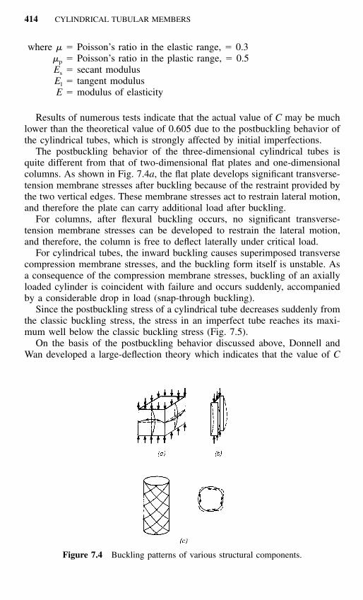
Figure 7.4 Buckling patterns of various structural components.
where � � Poisson’s ratio in the elastic range, � 0.3�p � Poisson’s ratio in the plastic range, � 0.5Es � secant modulusEl � tangent modulusE � modulus of elasticity
Results of numerous tests indicate that the actual value of C may be muchlower than the theoretical value of 0.605 due to the postbuckling behavior ofthe cylindrical tubes, which is strongly affected by initial imperfections.
The postbuckling behavior of the three-dimensional cylindrical tubes isquite different from that of two-dimensional flat plates and one-dimensionalcolumns. As shown in Fig. 7.4a, the flat plate develops significant transverse-tension membrane stresses after buckling because of the restraint provided bythe two vertical edges. These membrane stresses act to restrain lateral motion,and therefore the plate can carry additional load after buckling.
For columns, after flexural buckling occurs, no significant transverse-tension membrane stresses can be developed to restrain the lateral motion,and therefore, the column is free to deflect laterally under critical load.
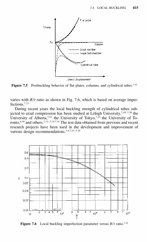
For cylindrical tubes, the inward buckling causes superimposed transversecompression membrane stresses, and the buckling form itself is unstable. Asa consequence of the compression membrane stresses, buckling of an axiallyloaded cylinder is coincident with failure and occurs suddenly, accompaniedby a considerable drop in load (snap-through buckling).
Since the postbuckling stress of a cylindrical tube decreases suddenly fromthe classic buckling stress, the stress in an imperfect tube reaches its maxi-mum well below the classic buckling stress (Fig. 7.5).
On the basis of the postbuckling behavior discussed above, Donnell andWan developed a large-deflection theory which indicates that the value of C
7.4 LOCAL BUCKLING 415
Figure 7.5 Postbuckling behavior of flat plates, columns, and cylindrical tubes.7.16
Figure 7.6 Local buckling imperfection parameter versus R / t ratio.7.16
varies with R/t ratio as shown in Fig. 7.6, which is based on average imper-fections.7.17
During recent years the local buckling strength of cylindrical tubes sub-jected to axial compression has been studied at Lehigh University,7.18–7.20 theUniversity of Alberta,7.21 the University of Tokyo,7.22 the University of To-ronto,6.30 and others.7.11–7.15,7.31 The test data obtained from previous and recentresearch projects have been used in the development and improvement ofvarious design recommendations.1.4,7.23–7.25

416 CYLINDRICAL TUBULAR MEMBERS
7.4.2 Local Buckling under Bending
The local buckling behavior in the compression portion of a flexural tubularmember is somewhat different compared with that of the axially loaded com-pression member. On the basis of their tests and theoretical investigation,Gerard and Becker7.16 suggested that elastic local buckling stress for bendingbe taken as 1.3 times the local buckling stress for axial compression. Thishigher elastic buckling stress for bending results from the beneficial effect ofthe stress gradient that exists in bending. However, some investigators haveindicated that there is not much difference between the critical stress in bend-ing and that in axial compression.3.84
The bending strength of cylindrical tubes has been studied by Sherman,7.26
and by Stephens, Kulak, and Montgomery.7.21
7.4.3 Local Buckling under Torsion
The theoretical local buckling stress of moderate-length tubes subjected totorsion can be computed by7.2
5 / 4 1 / 20.596a t R(� ) � E � � � �cr torsion 2 5 / 8(1 � � ) R L (7.16)
5 / 4 1 / 2t R� 0.632aE � � � �R L
where �cr is the critical shear buckling stress due to torsion and,
3 / 421 � � E Es sa � � 1.16 (7.17)� � � �21 � � E Ep
Previous studies indicate that the effect of imperfection on torsional post-buckling is much less than the effect on axial compression. Test data indicatethat due to the effect of initial imperfection, the actual strength of the memberis smaller than the analytical result.
7.4.4 Local Buckling under Transverse Shear
In Ref. 7.2, Schilling suggests that in the elastic range, the critical shearbuckling stress in transverse shear be taken as 1.25 times the critical shearbuckling stress due to torsion, that is,
5 / 4 1 / 2t R(� ) � 1.25 � 0.632aE � � � �cr transverse shear R L (7.18)
5 / 4 1 / 2t R� 0.79aE � � � �R L

7.5 AISI DESIGN CRITERIA1.314 417
7.4.5 Local Buckling under Combined Loading
The following interaction formula may be used for any combined loading:7.2
2ƒ �� � 1 (7.19)� � � �ƒ �cr cr
where ƒ � actual computed normal stressƒcr � critical buckling stress for normal stress alone
� � actual computed shear stress�cr � critical buckling stress for shear stress alone
7.5 AISI DESIGN CRITERIA1.314
The AISI design criteria for cylindrical tabular members were revised in the1986 and 1996 editions of the specification on the basis of Refs. 1.158, 7.5,and 7.30. For additional information, the reader is referred to Refs. 8.25through 8.32.
7.5.1 Local Buckling Stress
Considering the postbuckling behavior of the axially compressed cylinder andthe important effect of the initial imperfection, the design provisions includedin the AISI Specification were originally based on Plantema’s graphic rep-resentation7.27 and the additional results of cylindrical shell tests made byWilson and Newmark at the University of Illinois.7.28,7.29
From the tests of compressed tubes, Plantema found that the ratio Fult /Fy
depends on the parameter (E/Fy)(t /D), in which t is the wall thickness, D isthe mean diameter of the tubes, and Fult is the ultimate stress or collapsestress. As shown in Fig. 7.7, line 1 corresponds to the collapse stress belowthe proportional limit, line 2 corresponds to the collapse stress between theproportional limit and the yield point (the approximate proportional limit is83% of Fy at point B), and line 3 represents the collapse stress occurring atyield point. In the range of line 3, local buckling will not occur before yield-ing, and no stress reduction is necessary.
In ranges 1 and 2, local buckling occurs before the yield point is reached.In these cases the stress should be reduced to safeguard against local buckling.
As shown in Fig. 7.7, point A represents a specific value of (E/Fy)(t /D) �8, which divides yielding and local buckling. Using E � 29.5 � 103 ksi (203GPa), it can be seen that tubes with D/t ratios of no more than 0.125E/Fy are safe from failure caused by local buckling. Specifically, Plantema’sequations are as follows:7.4

418 CYLINDRICAL TUBULAR MEMBERS
Figure 7.7 Ultimate strength of cylindrical tubes for local buckling.
1. For D/t � 0.125E/Fy (yielding failure criterion represented by line 3),
Fult � 1 (7.20)Fy
2. For 0.125E/Fy � D/t � 0.4E/Fy (inelastic buckling criterion repre-sented by line 2),
F E tult � 0.031 � 0.75 (7.21)� �� �F F Dy y
3. For D/t � 0.4E/Fy (elastic buckling criterion represented by line 1),
F E tult � 0.33 (7.22)� �� �F F Dy y
Based on a conservative approach, AISI specifies that when the D/t ratiois smaller than or equal to 0.112E/Fy, the tubular member shall be designedfor yielding. This provision is based on point A1, for which (E/Fy)(t /D) �8.93.
7.5 AISI DESIGN CRITERIA1.314 419
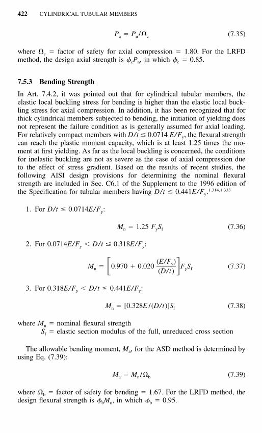
Figure 7.8 Correlation between test data and AISI criteria for local buckling ofcylindrical tubes under axial compression.
When 0.112E/Fy � D/t �0.441 E/Fy, the design of tubular members isbased on the local buckling criteria. For the purpose of developing a designformula for inelastic buckling, point B1 was selected by AISI to represent theproportional limit. For point B1,
E t Fult� 2.27 and � 0.75 (7.23)� �� �F D Fy y
Using line A1B1, the maximum stress of tubes can be represented by
F E tult � 0.037 � 0.667 (7.24)� �� �F F Dy y
The correlation between the available test data and Eq. (7.24) is shown inFig. 7.8.
Let A be the area of the unreduced cross section and A0 be the reducedarea due to local buckling, then
AF � A F (7.25)ult 0 y
or

420 CYLINDRICAL TUBULAR MEMBERS
FultA � A (7.26)� �0 Fy
Substituting Eq. (7.24) into Eq. (7.26), the following equation can be obtainedfor D/t � 0.441E/Fy:
0.037A � � 0.667 A � A (7.27)� �0 (D/t)(F /E)y
where D is the outside diameter of the cylindrical tubular member.
7.5.2 Compressive Strength
When a cylindrical tubular member is subject to a compressive load in thedirection of the member axis passing through the centroid of the section, theAISI design provision was changed in the 1996 Specification to reflect theresults of additional studies of cylindrical tubular members and to be consis-tent with Sec. C4 of the Specification. The following equations are now in-cluded in Sec. C6.2 of the AISI Specification and Supplement No. 1 fordetermining the nominal axial strength Pn of cylindrical tubular membershaving a ratio of outside diameter to wall thickness, D/t, not greater than0.441E/Fy.
1.314,1.333
P � F A (7.28)n n e
where Pn � nominal axial strength of the memberFn � flexural buckling stress determined as follows:
For c � 1.5,
2cF � (0.658 )F (7.29)n y
For c � 1.5,
0.877F � F (7.30)� �n y2 c
where
Fy � (7.31)c �Fe
In the above equations,

7.5 AISI DESIGN CRITERIA1.314 421
Figure 7.9 Nominal compressive load of cylindrical tubular members.
Fe � the elastic flexural buckling stress determined according to Sec. C4.1of the Specification
Ae � effective area of the cylindrical tubular member under axial com-pression determined as follows:1.333
A � A � R (A � A ) (7.32)e 0 0
R � F /2F � 1.0 (7.33)y e
0.037A � � 0.667 A � A (7.34)� �0 (DF ) /(tE)y
A � area of the unreduced cross section
Equations (7.28) through (7.34) can be summarized in Fig. 7.9. It can be seenthat Eq. (7.32) gives Ae � Ao when c � 0, and Ae � A when c � The�2.latter is due to the fact that for long columns the stresses at which the columnbuckles are so low that they will not cause local buckling before primarybuckling has taken place.
Consequently, for the design of axially loaded cylindrical tubular members,the allowable axial load Pa for the ASD method is determined by Eq. (7.35):
422 CYLINDRICAL TUBULAR MEMBERS
P � P / (7.35)a n c
where c � factor of safety for axial compression � 1.80. For the LRFDmethod, the design axial strength is �cPn, in which �c � 0.85.
7.5.3 Bending Strength
In Art. 7.4.2, it was pointed out that for cylindrical tubular members, theelastic local buckling stress for bending is higher than the elastic local buck-ling stress for axial compression. In addition, it has been recognized that forthick cylindrical members subjected to bending, the initiation of yielding doesnot represent the failure condition as is generally assumed for axial loading.For relatively compact members with D/t � 0.0714 E/Fy, the flexural strengthcan reach the plastic moment capacity, which is at least 1.25 times the mo-ment at first yielding. As far as the local buckling is concerned, the conditionsfor inelastic buckling are not as severe as the case of axial compression dueto the effect of stress gradient. Based on the results of recent studies, thefollowing AISI design provisions for determining the nominal flexuralstrength are included in Sec. C6.1 of the Supplement to the 1996 edition ofthe Specification for tubular members having D/t � 0.441E/Fy.
1.314,1.333
1. For D/t � 0.0714E/Fy:
M � 1.25 F S (7.36)n y f
2. For 0.0714E/Fy � D/t � 0.318E/Fy:
(E/F )yM � 0.970 � 0.020 F S (7.37)� �n y f(D/t)
3. For 0.318E/Fy � D/t � 0.441E/Fy:
M � [0.328E / (D/t)]S (7.38)n f
where Mn � nominal flexural strengthSf � elastic section modulus of the full, unreduced cross section
The allowable bending moment, Ma, for the ASD method is determined byusing Eq. (7.39):
M � M / (7.39)a n b
where b � factor of safety for bending � 1.67. For the LRFD method, thedesign flexural strength is �bMn, in which �b � 0.95.
7.6 DESIGN EXAMPLES 423
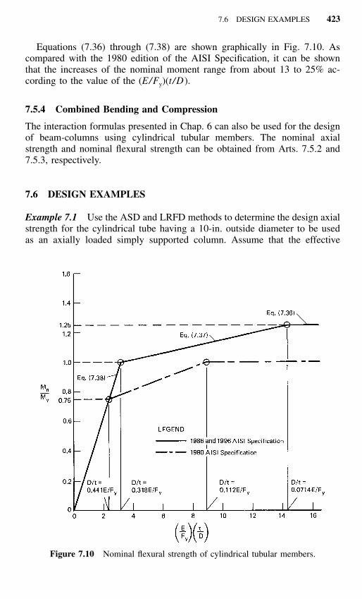
Figure 7.10 Nominal flexural strength of cylindrical tubular members.
Equations (7.36) through (7.38) are shown graphically in Fig. 7.10. Ascompared with the 1980 edition of the AISI Specification, it can be shownthat the increases of the nominal moment range from about 13 to 25% ac-cording to the value of the (E/Fy)(t /D).
7.5.4 Combined Bending and Compression
The interaction formulas presented in Chap. 6 can also be used for the designof beam-columns using cylindrical tubular members. The nominal axialstrength and nominal flexural strength can be obtained from Arts. 7.5.2 and7.5.3, respectively.
7.6 DESIGN EXAMPLES
Example 7.1 Use the ASD and LRFD methods to determine the design axialstrength for the cylindrical tube having a 10-in. outside diameter to be usedas an axially loaded simply supported column. Assume that the effective

424 CYLINDRICAL TUBULAR MEMBERS
column length is 15 ft, the yield point of steel is 33 ksi, and the thickness ofthe tube is 0.105 in.
Solution
A. ASD Method. Using the AISI design criteria, the limiting D/t ratio is
D E 29,500� 0.441 � 0.441 � 394.23� �t F 33ylim
The actual D/t ratio is
D 10� � 95.24 � 394.23 O.K.
t 0.105
1. Sectional Properties of Full Section
2 2�(D � D )o iA �4
2 2�[(10.0) � (10.0 � 2 � 0.105) ]�
42� 3.264 in.
2 2�D � Do ir �
42 2�(10.0) � (10.0 � 2 � 0.105)
� � 3.500 in.4
2. Nominal Axial Strength, Pn
a.KL 15 � 12
� � 51.43r 3.50
According to Eq. (5.56), the elastic flexural buckling stress is
2 2� E � (29,500)F � � � 110.08 ksie 2 2(KL/r) (51.43)

7.6 DESIGN EXAMPLES 425
b. Based on Eq. (7.31),
F 33y � � � 0.548 � 1.5c � �F 110.08e
2 2 0.548cF � (0.658 )F � (0.658 )(33)n y
� 29.10 ksi
c. Based on Eqs. (7.32), (7.33), and (7.34),
A � A � R(A � A )c o o
where
R � F /2Fy e
� 33/(2 � 110.08) � 0.150 � 1.0 O.K.
0.037A � � 0.667 A� �0 (D/t)(F /E)y
0.037� � 0.667 (3.264)� �(95.24)(33/29,500)
2� 3.311 in.Because 3.311 � A � 3.264 in.2, use A0 � 3.264 in.2 Therefore,
A � 3.264 � (0.150)(3.264 � 3.264)e
2� 3.264 in.
From Eq. (7.28), the nominal axial load is
P � F An n e
� (29.10)(3.264) � 94.98 kips
3. Allowable axial load, Pa . From Eq. (7.35), the allowable axial loadis
P � P / � 94.98/1.80a n c
� 52.77 kips
426 CYLINDRICAL TUBULAR MEMBERS
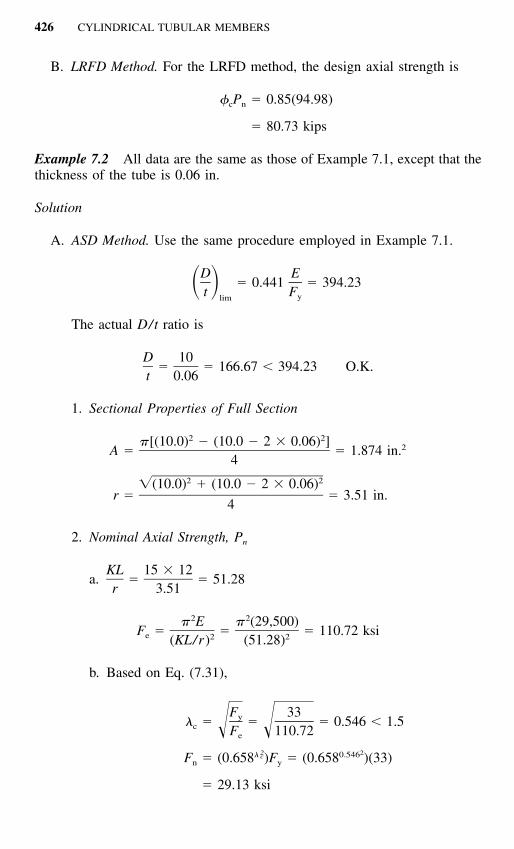
B. LRFD Method. For the LRFD method, the design axial strength is
� P � 0.85(94.98)c n
� 80.73 kips
Example 7.2 All data are the same as those of Example 7.1, except that thethickness of the tube is 0.06 in.
Solution
A. ASD Method. Use the same procedure employed in Example 7.1.
D E� 0.441 � 394.23� �t Fylim
The actual D/t ratio is
D 10� � 166.67 � 394.23 O.K.
t 0.06
1. Sectional Properties of Full Section
2 2�[(10.0) � (10.0 � 2 � 0.06) ] 2A � � 1.874 in.4
2 2�(10.0) � (10.0 � 2 � 0.06)r � � 3.51 in.
4
2. Nominal Axial Strength, Pn
a.KL 15 � 12
� � 51.28r 3.51
2 2� E � (29,500)F � � � 110.72 ksie 2 2(KL/r) (51.28)
b. Based on Eq. (7.31),
F 33y � � � 0.546 � 1.5c � �F 110.72e
2 2 0.546cF � (0.658 )F � (0.658 )(33)n y
� 29.13 ksi

7.6 DESIGN EXAMPLES 427
c. Based on Eqs. (7.32), (7.33), and (7.34),
A � A � R (A � A )e 0 0
where R � Fy /2Fe � 33/(2 � 110.72) � 0.149 � 1.0 O.K.
0.037 2A � � 0.667 (1.874) � 1.622 in.� �0 (166.67)(33/29,500)
Since A0 � A � 1.874 in.2, use A0 � 1.622 in.2
2A � 1.622 � (0.149)(1.874 � 1.622) � 1.660 in.e
The nominal axial strength is
P � F A � (29.13)(1.660) � 48.36 kipsn n e
3. Allowable Axial Load, Pa . From Eq. (7.35), the allowable axial loadis
P � P / � 48.36/1.80a n c
� 26.87 kips
B. LRFD Method. For the LRFD method, the design axial strength is
� P � 0.85(48.36)c n
� 41.11 kips
Example 7.3 Use the ASD and LRFD methods to determine the designflexural strength of cylindrical tubes used in Examples 7.1 and 7.2 if thesetubes are to be used as flexural members.
Solution
A. ASD Method1. Use the data given in Example 7.1,
F � 33 ksiy
D � 10 in.o
t � 0.105 in.
D/t � 95.24 � 0.441E/F O.K.y
428 CYLINDRICAL TUBULAR MEMBERS
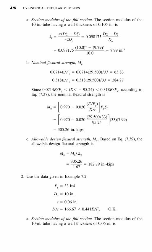
a. Section modulus of the full section. The section modulus of the10-in. tube having a wall thickness of 0.105 in. is
4 4 4 4�(D � D ) D � Do i o iS � � 0.098175f 32D Do o
4 4(10.0) � (9.79) 3� 0.098175 � 7.99 in.10.0
b. Nominal flexural strength, Mn
0.0714E/F � 0.0714(29,500)/33 � 63.83y
0.318E/F � 0.318(29,500)/33 � 284.27y
Since 0.0714E/Fy � (D/t � 95.24) � 0.318E/Fy, according toEq. (7.37), the nominal flexural strength is
(E/F )yM � 0.970 � 0.020 F S� �n y fD/t
(29,500/33)� 0.970 � 0.020 (33)(7.99)� �95.24
� 305.26 in.-kips
c. Allowable design flexural strength, Ma . Based on Eq. (7.39), theallowable design flexural strength is
M � M /a n b
305.26� � 182.79 in.-kips
1.67
2. Use the data given in Example 7.2,
F � 33 ksiy
D � 10 in.o
t � 0.06 in.
D/t � 166.67 � 0.441E/F O.K.y
a. Section modulus of the full section. The section modulus of the10-in. tube having a wall thickness of 0.06 in. is

7.6 DESIGN EXAMPLES 429
4 4(10.0) � (9.88) 3S � 0.098175 � 4.628 in.f 10.0
b. Nominal flextural strength, Mn . Since 0.0714E/Fy � D/t �0.318E/Fy,
(29,500/33)M � 0.970 � 0.020 (33)(4.628)� �n 166.67
� 164.53 in.-kips
c. Allowable design flexural strength, Ma . The allowable designflexural strength is
M � M /a n b
164.53� � 98.52 in.-kips.
1.67
B. LRFD MethodUsing the LRFD method, the design flexural strengths for the cylin-
drical tubes used in Examples 7.1 and 7.2 can be computed as follows:1. For the cylindrical tube used in Example 7.1, the nominal flexural
strength computed in Item (A) above is
M � 305.26 in.-kipsn
The design flexural strength is
� M � 0.95(305.26) � 290.00 in.-kipsb n
2. For the cylindrical tube used in Example 7.2, the nominal flexuralstrength computed in Item (A) above is
M � 164.53 in.-kipsn
The design flexural strength is
� M � 0.95(164.53) � 156.30 in.-kipsb n


