5200 Convair Dr Carson City, NV 89706 PDO … PDO2... · 2013-07-22 · 5200 convair dr carson...
35
5200 Convair Dr Carson City, NV 89706 775.883.2500 Fax 775.883.6388 www.BAT4pH.com See us on the WEB at http://www.BAT4pH.com e-mail address: [email protected] Manual PDO 2 -E rev 5/11/2010 PDO 2 Series OPTICAL DISSOLVED OXYGEN SYSTEM
Transcript of 5200 Convair Dr Carson City, NV 89706 PDO … PDO2... · 2013-07-22 · 5200 convair dr carson...

5200 Convair Dr
Carson City, NV 89706
775.883.2500 Fax 775.883.6388
www.BAT4pH.com
See us on the WEB at http://www.BAT4pH.com
e-mail address: [email protected]
Manual PDO2-E rev 5/11/2010
PDO2 Series OPTICAL DISSOLVED
OXYGEN SYSTEM
5200 Convair Dr
Carson City, NV 89706
775.883.2500 Fax 775.883.6388
www.BAT4pH.com
LIMITED WARRANTY
ALL PRODUCTS MANUFACTURED BY BARBEN ANALYZER TECHNOLOGY, LLC
ARE WARRANTED TO BE FREE OF MANUFACTURING DEFECTS FOR A PERIOD OF
ONE YEAR FROM THE DATE OF RECEIPT AT THE CUSTOMER’S RECEIVING AREA.
THIS WARRANTY COVERS MATERIALS AND LABOR TO RESTORE ANY PRODUCTS
TO ORIGINAL FACTORY SPECIFICATIONS IF A DEFECT IS FOUND WITHIN THE
WARRANTY PERIOD.
AN RMA NEEDS TO BE OBTAINED FROM THE FACTORY PRIOR TO RETURNING
DEFECTIVE PRODUCT. IT MUST BE SENT, FREIGHT PREPAID, TO THE FACTORY IN
CARSON CITY, NEVADA. REPAIRS WILL BE PERFORMED AT THE FACTORY AND
RETURNED, PREPAID, BY THE SAME SHIPPING METHOD USED TO SEND THE
PRODUCT TO THE FACTORY.
THIS WARRANTY DOES NOT APPLY IF THE EQUIPMENT HAS SUSTAINED DAMAGE
DUE TO NEGLECT, MODIFICATION, CORROSION, OR OTHER REASON BEYOND THE
SCOPE OF THE NORMAL DEFINITION OF “MANUFACTURING DEFECT”.
FURTHER, THIS WARRANTY IS LIMITED TO REPLACING THE DEFECTIVE
COMPONENTS AND RETURNING THE EQUIPMENT MANUFACTURED BY BARBEN
ANALYZER TECHNOLOGY, LLC TO THE CUSTOMER IN WORKING CONDITION.
ANY OTHER CLAIMS ARE OUTSIDE THE SCOPE OF THIS WARRANTY. NO
WARRANTIES ARE MADE AS TO THE SUITABILITY OF THE USE OF THE
EQUIPMENT IN ANY PARTICULAR APPLICATION OR LOCATION. THE SUITABILITY
OF THE USE OF THE EQUIPMENT IS THE RESPONSIBILITY OF THE CUSTOMER AND
THE INSTALLING CONTRACTOR.
SERIES PDO2-E
5200 CONVAIR DR
CARSON CITY, NV 89706 PHONE: (775) 883-2500
FAX: (775) 883-6388
PDO2-E Draft Manual Rev 5/26/2010 Page 1
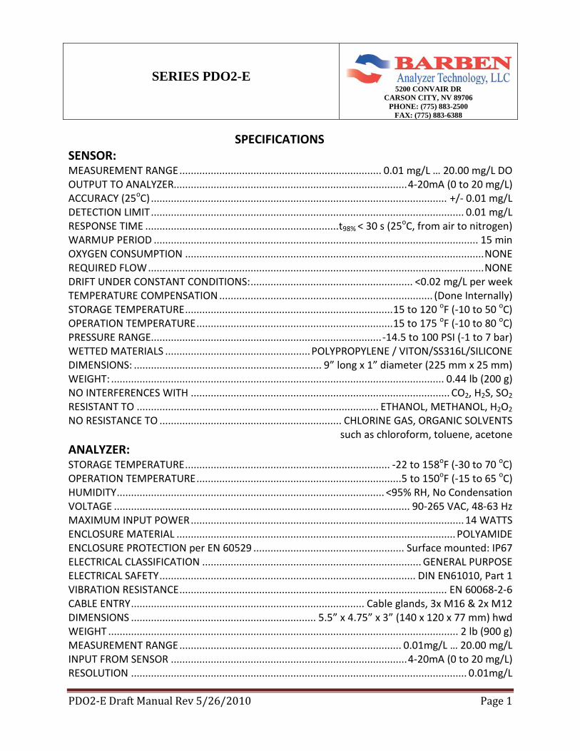
SPECIFICATIONS SENSOR: MEASUREMENT RANGE ....................................................................... 0.01 mg/L … 20.00 mg/L DO OUTPUT TO ANALYZER.................................................................................. 4-20mA (0 to 20 mg/L) ACCURACY (25oC) ........................................................................................................ +/- 0.01 mg/L DETECTION LIMIT .............................................................................................................. 0.01 mg/L RESPONSE TIME .................................................................... t98% < 30 s (25oC, from air to nitrogen) WARMUP PERIOD .................................................................................................................. 15 min OXYGEN CONSUMPTION ......................................................................................................... NONE REQUIRED FLOW ...................................................................................................................... NONE DRIFT UNDER CONSTANT CONDITIONS: ......................................................... <0.02 mg/L per week TEMPERATURE COMPENSATION ........................................................................... (Done Internally) STORAGE TEMPERATURE ......................................................................... 15 to 120 oF (-10 to 50 oC) OPERATION TEMPERATURE ..................................................................... 15 to 175 oF (-10 to 80 oC) PRESSURE RANGE................................................................................. -14.5 to 100 PSI (-1 to 7 bar) WETTED MATERIALS ................................................... POLYPROPYLENE / VITON/SS316L/SILICONE DIMENSIONS: .................................................................. 9” long x 1” diameter (225 mm x 25 mm) WEIGHT: ..................................................................................................................... 0.44 lb (200 g) NO INTERFERENCES WITH ........................................................................................... CO2, H2S, SO2 RESISTANT TO ..................................................................................... ETHANOL, METHANOL, H2O2 NO RESISTANCE TO ................................................................ CHLORINE GAS, ORGANIC SOLVENTS
such as chloroform, toluene, acetone ANALYZER: STORAGE TEMPERATURE ........................................................................ -22 to 158oF (-30 to 70 oC) OPERATION TEMPERATURE ........................................................................ 5 to 150oF (-15 to 65 oC) HUMIDITY .............................................................................................. <95% RH, No Condensation VOLTAGE ........................................................................................................ 90-265 VAC, 48-63 Hz MAXIMUM INPUT POWER ................................................................................................ 14 WATTS ENCLOSURE MATERIAL .................................................................................................. POLYAMIDE ENCLOSURE PROTECTION per EN 60529 ..................................................... Surface mounted: IP67 ELECTRICAL CLASSIFICATION ............................................................................. GENERAL PURPOSE ELECTRICAL SAFETY .......................................................................................... DIN EN61010, Part 1 VIBRATION RESISTANCE .............................................................................................. EN 60068-2-6 CABLE ENTRY .................................................................................. Cable glands, 3x M16 & 2x M12 DIMENSIONS ................................................................. 5.5” x 4.75” x 3” (140 x 120 x 77 mm) hwd WEIGHT ........................................................................................................................... 2 lb (900 g) MEASUREMENT RANGE .............................................................................. 0.01mg/L … 20.00 mg/L INPUT FROM SENSOR ................................................................................... 4-20mA (0 to 20 mg/L) RESOLUTION ...................................................................................................................... 0.01mg/L
PDO2-E Draft Manual Rev 5/26/2010 Page 2
Important note: Copyright © 2010 Barben Analyzer Technology (BAT), LLC, Carson City, NV, USA. All rights reserved. The reproduction of any part of this document in any form is forbidden without the express written agreement of Barben Analyzer Technology, LLC. Contents of this manual can be modified without previous notification. Technical modifications reserved. Greatest possible care was used to make sure the information in this manual is correct and accurate. If errors are discovered, Barben Analyzer Technology, LLC would be pleased to be informed about it. Regardless of this, Barben Analyzer Technology, LLC cannot assume liability for any errors in this manual or for their consequences.
PDO2-E Draft Manual Rev 5/26/2010 Page 3
Table of Contents 1 GENERAL INFORMATION ................................................................................................. 5
1.1 Safety Information............................................................................................................ 5
1.2 PDO2 System Information ................................................................................................ 5
1.3 Theory of Operation ......................................................................................................... 5
2 MOUNTING ........................................................................................................................... 6
2.1 Controller ......................................................................................................................... 6
2.1.1 Surface / plate mounting ........................................................................................... 6
2.1.2 Pipe installation set / weather protection roof (Ordered Separately) ........................ 7
2.2 SENSOR........................................................................................................................... 8
2.2.1 Installing the sensor in the sample stream ................................................................ 8
3 Wiring ..................................................................................................................................... 8
3.1 Controller ......................................................................................................................... 8
3.1.1 Instructions ................................................................................................................ 8
3.1.2 Connection ................................................................................................................ 9
3.2 Sensor ............................................................................................................................. 10
3.2.1 Connecting Sensor to Controller ............................................................................. 10
4 User Interface and Navigation .............................................................................................. 10
4.1 Normal Display .............................................................................................................. 11
4.2 Min / Max Display ......................................................................................................... 11
4.3 Programming Display .................................................................................................... 12
4.3.1 CONFIGURE .......................................................................................................... 12
4.3.2 CALIB. LEVEL ...................................................................................................... 13
4.3.3 CALIB. LOGBOOK ............................................................................................... 13
4.3.4 DEVICE INFO........................................................................................................ 13
5 Operation............................................................................................................................... 14
5.1 Calibrating the Sensor .................................................................................................... 14
5.1.1 Single Point Calibration in Water Saturated Air..................................................... 14
6 Maintenance .......................................................................................................................... 15
6.1 Routine Maintenance...................................................................................................... 15
6.2 Cleaning the Sensor ........................................................................................................ 16
6.3 Changing the Sensor Cap ............................................................................................... 16
PDO2-E Draft Manual Rev 5/26/2010 Page 4
7 Troubleshooting .................................................................................................................... 17
7.1 Error Codes .................................................................................................................... 17
7.2 Warnings ........................................................................................................................ 17
8 Replacement Parts and Accessories ...................................................................................... 18
9 Terms .................................................................................................................................... 19
9.1 Pricing ............................................................................................................................ 19
9.2 Payment Terms ............................................................................................................... 19
9.3 Freight ............................................................................................................................ 19
9.4 Returns ........................................................................................................................... 19
9.5 Limited Warranty ........................................................................................................... 19
10 Drawings: .............................................................................................................................. 20
Appendix A: Altitude to Atmospheric Pressure Conversion ............................................. 21
Appendix B: Solubility of Oxygen at Various Temperatures and Pressures ..................... 23
PDO2-E Draft Manual Rev 5/26/2010 Page 5
1 GENERAL INFORMATION 1.1 Safety Information Please read this entire manual before unpacking, setting up, or operating this equipment. Pay attention to all danger and caution statements. Failure to do so could result in serious injury to the operator or damage to the equipment. To ensure that the protection provided by this equipment is not impaired, do not use or install this equipment in any manner other than that specified in this manual. The specifications such as temperature or pressure being defined on page one in Specifications may not be exceeded under any circumstances. Threats are imminent if the sensor is not operated correctly or appropriately. 1.2 PDO2 System Information The PDO2 luminescent (fluorescence) dissolved oxygen System (1401DO analyzer & sensor combination) differs from industry standard polarographic-style DO sensors in several ways. The principal distinguishing factors relate to the durability of the sensing element and the stability of the signal, both of which have been significantly improved in the PDO2 luminescent dissolved oxygen sensor. These changes mark an important step forward in wastewater and industrial monitoring. The PDO2 luminescent dissolved oxygen sensor operates by shining a blue light of the proper wavelength on a luminescent dye which is immobilized in a matrix and formed into a disk about 0.5 inches in diameter. This dye-containing disk will be evident on inspection of the sensor face. The blue light causes the immobilized dye to luminesce and the lifetime of this dye luminescence is measured via a photodiode in the probe. When there is no oxygen present, the luminescence lifetime of the signal is maximal; as oxygen is introduced to the membrane surface of the sensor, the luminescence lifetime becomes shorter. Thus, the lifetime of the luminescence is inversely proportional to the amount of oxygen present and the relationship between the oxygen concentration outside the sensor and the luminescence lifetime can be quantified. With PDO2 luminescent dissolved oxygen Sensor, there is only one consumable. Under normal conditions, even with frequent steam sterilizing, autoclaving, and CIPs, the Sensor Cap has a lifetime of more than one year. Furthermore, lifetime is seldom dramatically reduced— even in environmental applications, the Sensor Cap lasts for 1 to 3 years or longer. 1.3 Theory of Operation The unique design of the PDO2 luminescent dissolved oxygen Sensor enables it to monitor the status of the sensor’s blue LED using one of the photodiodes. The photodiode with the red filter measures the oxygen-dependent red light generated on the luminophore (Optode) through luminescence (fluorescence) caused after excitation by the blue light. Electrons are excited to a higher energy level, and return to their original level after emission of red light.
PDO2-E Draft Manual Rev 5/26/2010 Page 6
When the luminophore comes into contact with elemental oxygen, the O2 molecules absorb the energy, resulting in reduced intensity of red light emission. This difference in intensity is analyzed by the instrument’s self-monitoring system to pinpoint photobleaching (bleaching of the luminophore). High precision measurement of the optical phase shift between the blue and red light pulses provides accurate indication of oxygen concentration. Normally, the luminophore’s excited electrons remain in this state for some time. However, in the presence of oxygen they return to their ground state more quickly. An oxygen dependent time shift occurs between pulsed excitation of the luminophore and the emission of red light, measured as phase angle. Notice that PDO2 luminescent dissolved oxygen Sensors measure the partial pressure of oxygen (pO2) just as classical sensors do. This is displayed as concentration in mg/l (ppm). The measurement range is currently limited to 0.01 to 20 mg/L. For most applications this measurement range is more than adequate 2 MOUNTING 2.1 Controller The mounting location for the 1401DO analyzer should allow for easy access to view the screen and push buttons. The display screen should be located out of direct sunlight, but can be oriented in any position.
2.1.1 Surface / plate mounting Mounting tabs are included with shipment. Attach the four mounting tabs onto the enclosure then fasten the enclosure with tabs onto a surface or plate.
PDO2-E Draft Manual Rev 5/26/2010 Page 7
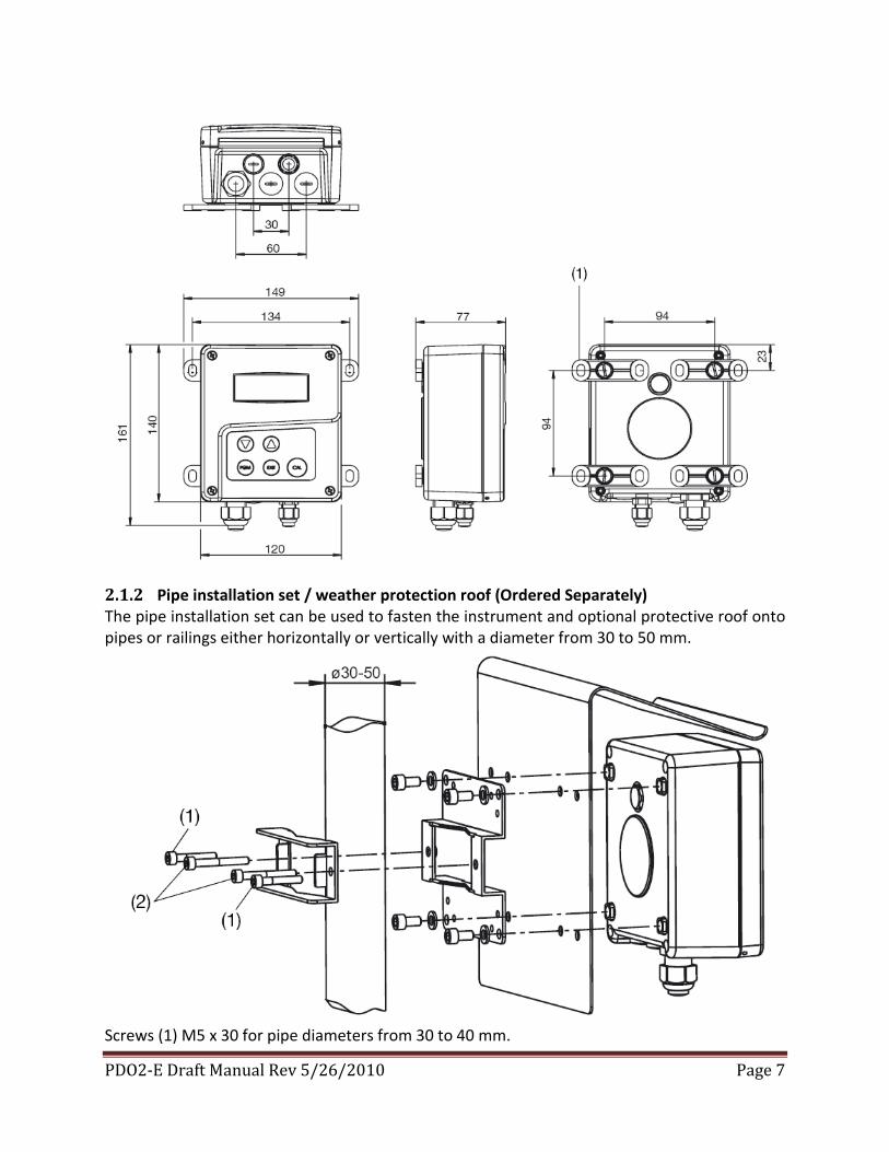
2.1.2 Pipe installation set / weather protection roof (Ordered Separately) The pipe installation set can be used to fasten the instrument and optional protective roof onto pipes or railings either horizontally or vertically with a diameter from 30 to 50 mm.
Screws (1) M5 x 30 for pipe diameters from 30 to 40 mm.
PDO2-E Draft Manual Rev 5/26/2010 Page 8
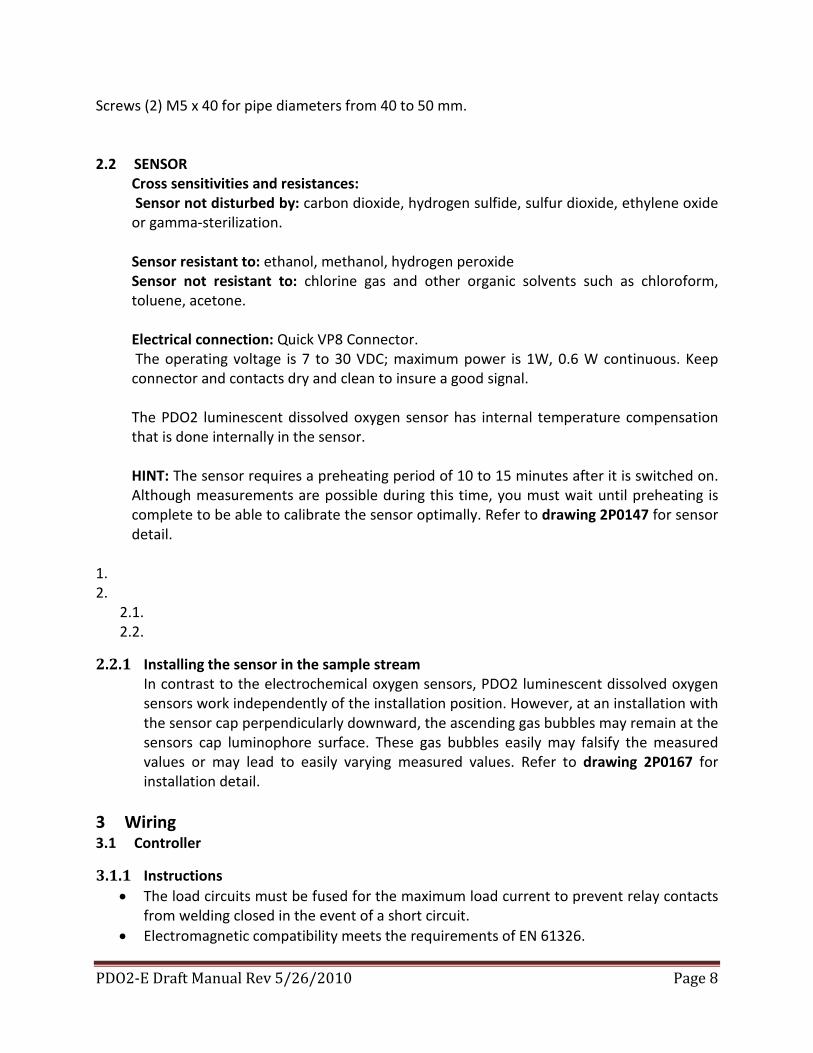
Screws (2) M5 x 40 for pipe diameters from 40 to 50 mm. 2.2 SENSOR
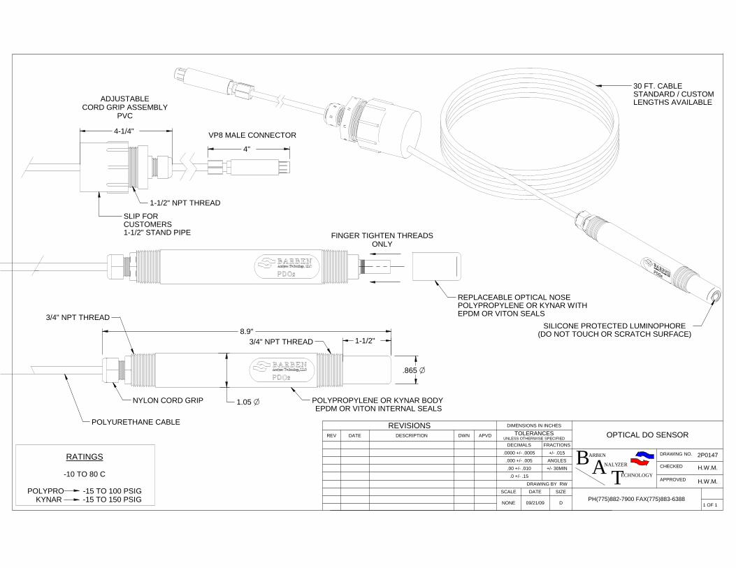
Cross sensitivities and resistances: Sensor not disturbed by: carbon dioxide, hydrogen sulfide, sulfur dioxide, ethylene oxide or gamma-sterilization. Sensor resistant to: ethanol, methanol, hydrogen peroxide Sensor not resistant to: chlorine gas and other organic solvents such as chloroform, toluene, acetone. Electrical connection: Quick VP8 Connector. The operating voltage is 7 to 30 VDC; maximum power is 1W, 0.6 W continuous. Keep connector and contacts dry and clean to insure a good signal. The PDO2 luminescent dissolved oxygen sensor has internal temperature compensation that is done internally in the sensor. HINT: The sensor requires a preheating period of 10 to 15 minutes after it is switched on. Although measurements are possible during this time, you must wait until preheating is complete to be able to calibrate the sensor optimally. Refer to drawing 2P0147 for sensor detail.
1. 2.
2.1. 2.2.
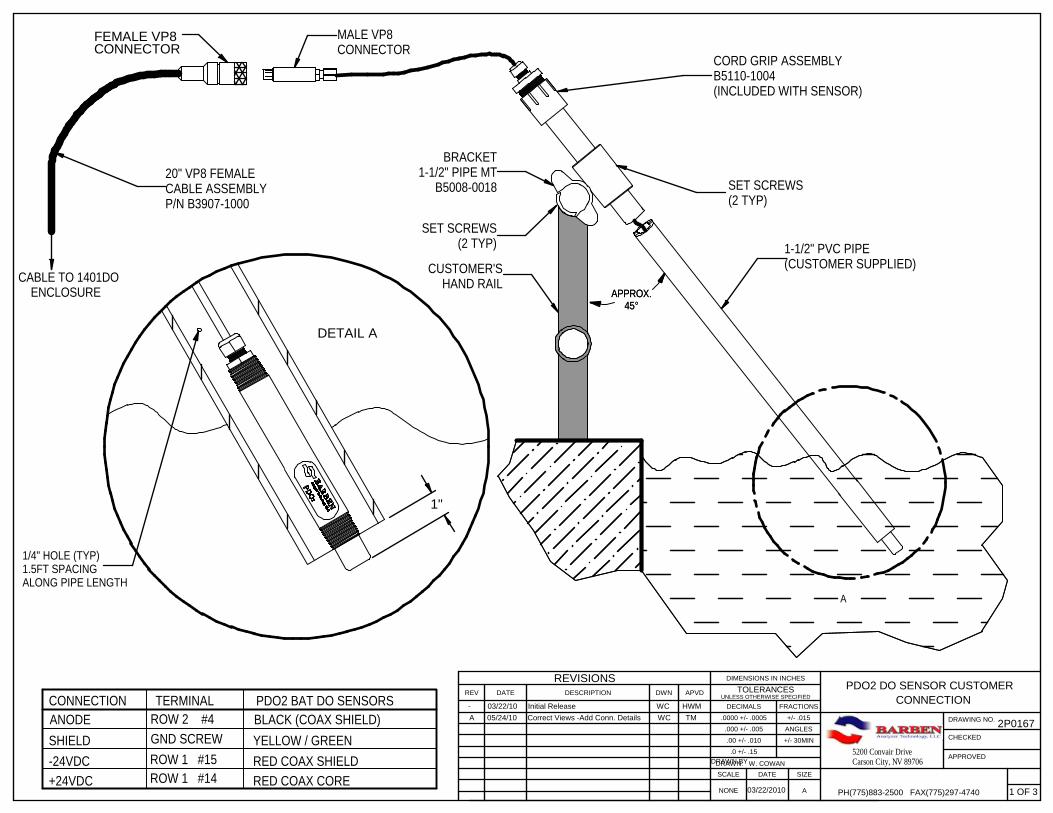
2.2.1 Installing the sensor in the sample stream In contrast to the electrochemical oxygen sensors, PDO2 luminescent dissolved oxygen sensors work independently of the installation position. However, at an installation with the sensor cap perpendicularly downward, the ascending gas bubbles may remain at the sensors cap luminophore surface. These gas bubbles easily may falsify the measured values or may lead to easily varying measured values. Refer to drawing 2P0167 for installation detail.
3 Wiring 3.1 Controller
3.1.1 Instructions • The load circuits must be fused for the maximum load current to prevent relay contacts
from welding closed in the event of a short circuit. • Electromagnetic compatibility meets the requirements of EN 61326.
PDO2-E Draft Manual Rev 5/26/2010 Page 9
• Lay the input, output, and supply lines so they are physically separated from each other and are not parallel.
• Do not route the sensor cable close to wires or components in which current is flowing. • The instrument is not suitable for explosion proof classified areas. • The enclosure protection specified for the instrument (IP67) is only achievable if a cable
runs into the instrument thru a cable gland.
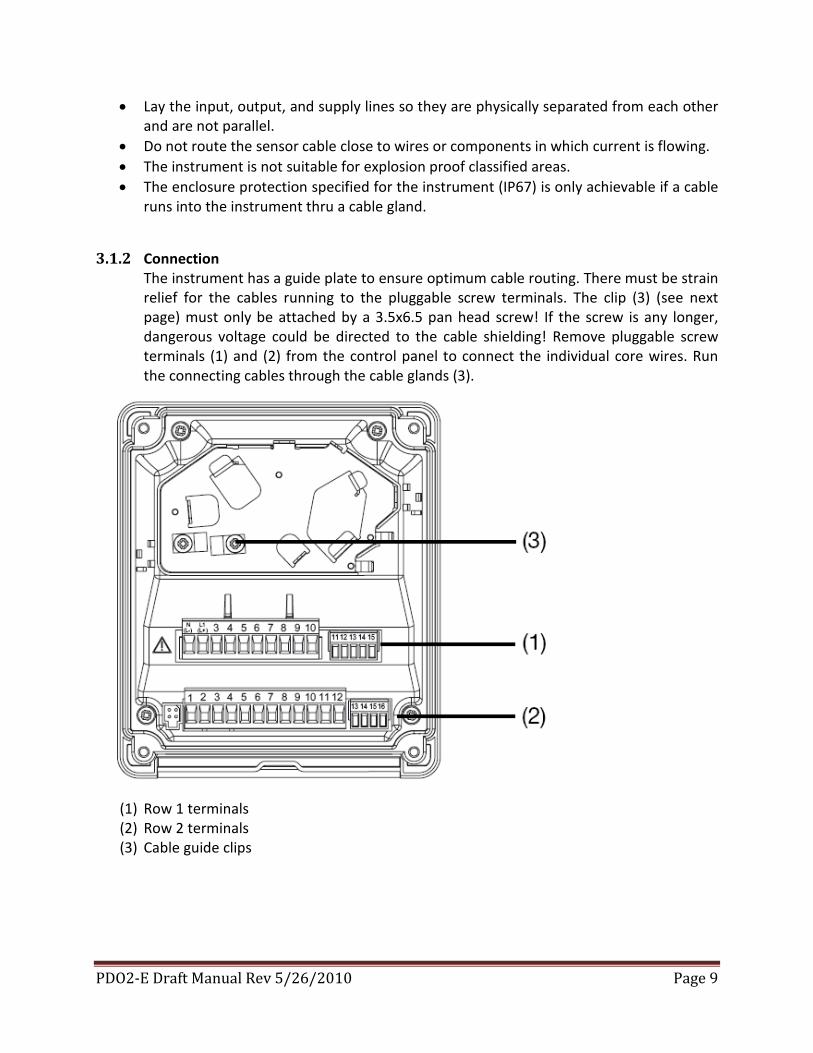
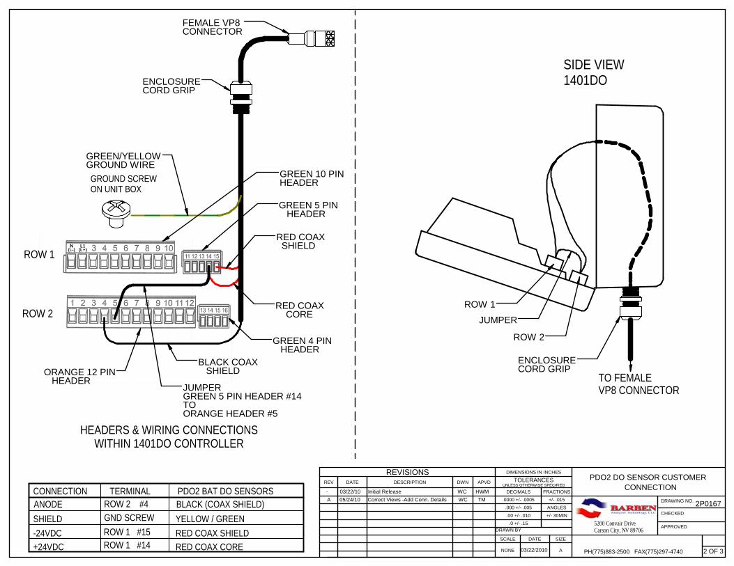
3.1.2 Connection The instrument has a guide plate to ensure optimum cable routing. There must be strain relief for the cables running to the pluggable screw terminals. The clip (3) (see next page) must only be attached by a 3.5x6.5 pan head screw! If the screw is any longer, dangerous voltage could be directed to the cable shielding! Remove pluggable screw terminals (1) and (2) from the control panel to connect the individual core wires. Run the connecting cables through the cable glands (3).
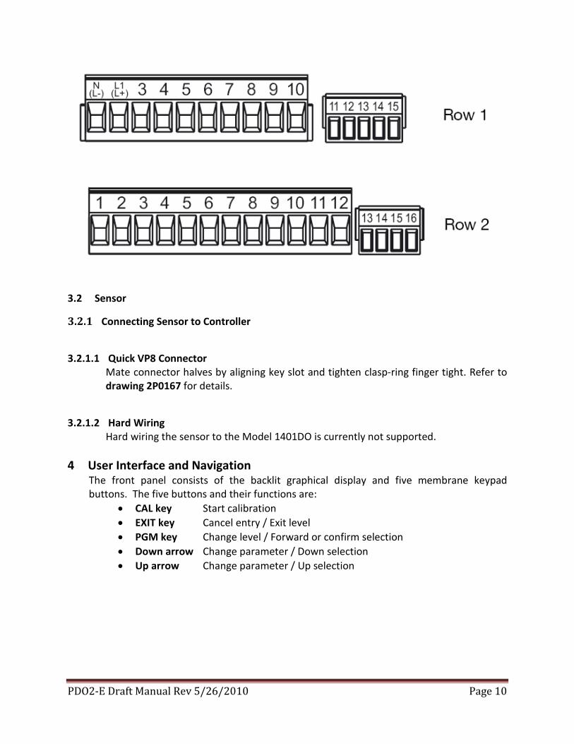
(1) Row 1 terminals (2) Row 2 terminals (3) Cable guide clips
PDO2-E Draft Manual Rev 5/26/2010 Page 10
3.2 Sensor
3.2.1 Connecting Sensor to Controller
3.2.1.1 Quick VP8 Connector Mate connector halves by aligning key slot and tighten clasp-ring finger tight. Refer to drawing 2P0167 for details.
3.2.1.2 Hard Wiring Hard wiring the sensor to the Model 1401DO is currently not supported.
4 User Interface and Navigation
The front panel consists of the backlit graphical display and five membrane keypad buttons. The five buttons and their functions are:
• CAL key Start calibration • EXIT key Cancel entry / Exit level • PGM key Change level / Forward or confirm selection • Down arrow Change parameter / Down selection • Up arrow Change parameter / Up selection
PDO2-E Draft Manual Rev 5/26/2010 Page 11
4.1 Normal Display
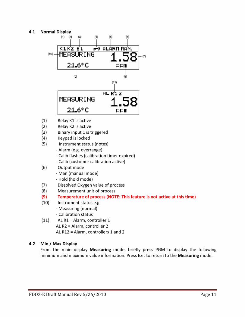
(1) Relay K1 is active (2) Relay K2 is active (3) Binary input 1 is triggered (4) Keypad is locked (5) Instrument status (notes)
- Alarm (e.g. overrange) - Calib flashes (calibration timer expired) - Calib (customer calibration active)
(6) Output mode - Man (manual mode) - Hold (hold mode)
(7) Dissolved Oxygen value of process (8) Measurement unit of process (9) Temperature of process (NOTE: This feature is not active at this time) (10) Instrument status e.g.
- Measuring (normal) - Calibration status
(11) AL R1 = Alarm, controller 1 AL R2 = Alarm, controller 2 AL R12 = Alarm, controllers 1 and 2
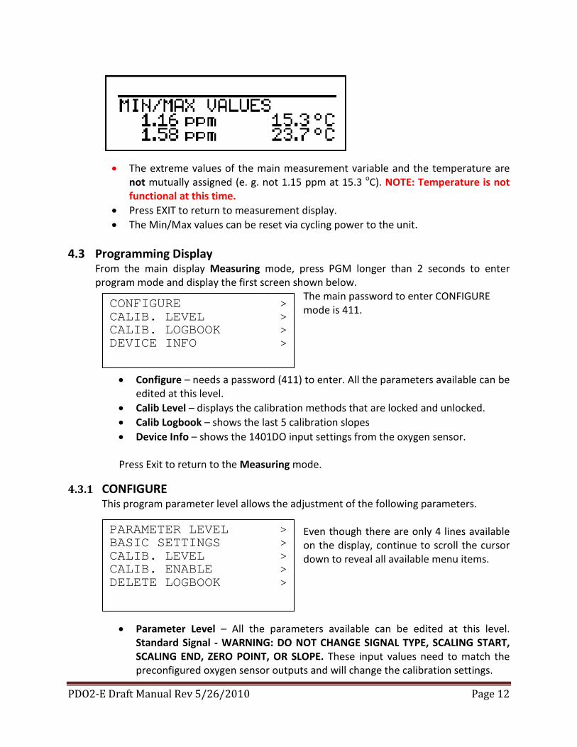
4.2 Min / Max Display
From the main display Measuring mode, briefly press PGM to display the following minimum and maximum value information. Press Exit to return to the Measuring mode.
PDO2-E Draft Manual Rev 5/26/2010 Page 12
• The extreme values of the main measurement variable and the temperature are
not mutually assigned (e. g. not 1.15 ppm at 15.3 oC). NOTE: Temperature is not functional at this time.
• Press EXIT to return to measurement display. • The Min/Max values can be reset via cycling power to the unit.
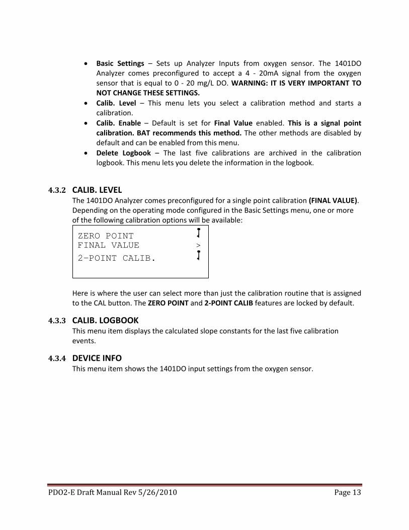
4.3 Programming Display
From the main display Measuring mode, press PGM longer than 2 seconds to enter program mode and display the first screen shown below.
The main password to enter CONFIGURE mode is 411.
• Configure – needs a password (411) to enter. All the parameters available can be edited at this level.
• Calib Level – displays the calibration methods that are locked and unlocked. • Calib Logbook – shows the last 5 calibration slopes • Device Info – shows the 1401DO input settings from the oxygen sensor. Press Exit to return to the Measuring mode.
4.3.1 CONFIGURE This program parameter level allows the adjustment of the following parameters.
Even though there are only 4 lines available on the display, continue to scroll the cursor down to reveal all available menu items.
• Parameter Level – All the parameters available can be edited at this level. Standard Signal - WARNING: DO NOT CHANGE SIGNAL TYPE, SCALING START, SCALING END, ZERO POINT, OR SLOPE. These input values need to match the preconfigured oxygen sensor outputs and will change the calibration settings.
CONFIGURE > CALIB. LEVEL > CALIB. LOGBOOK > DEVICE INFO >
PARAMETER LEVEL > BASIC SETTINGS > CALIB. LEVEL > CALIB. ENABLE > DELETE LOGBOOK >
PDO2-E Draft Manual Rev 5/26/2010 Page 13
• Basic Settings – Sets up Analyzer Inputs from oxygen sensor. The 1401DO
Analyzer comes preconfigured to accept a 4 - 20mA signal from the oxygen sensor that is equal to 0 - 20 mg/L DO. WARNING: IT IS VERY IMPORTANT TO NOT CHANGE THESE SETTINGS.
• Calib. Level – This menu lets you select a calibration method and starts a calibration.
• Calib. Enable – Default is set for Final Value enabled. This is a signal point calibration. BAT recommends this method. The other methods are disabled by default and can be enabled from this menu.
• Delete Logbook – The last five calibrations are archived in the calibration logbook. This menu lets you delete the information in the logbook.
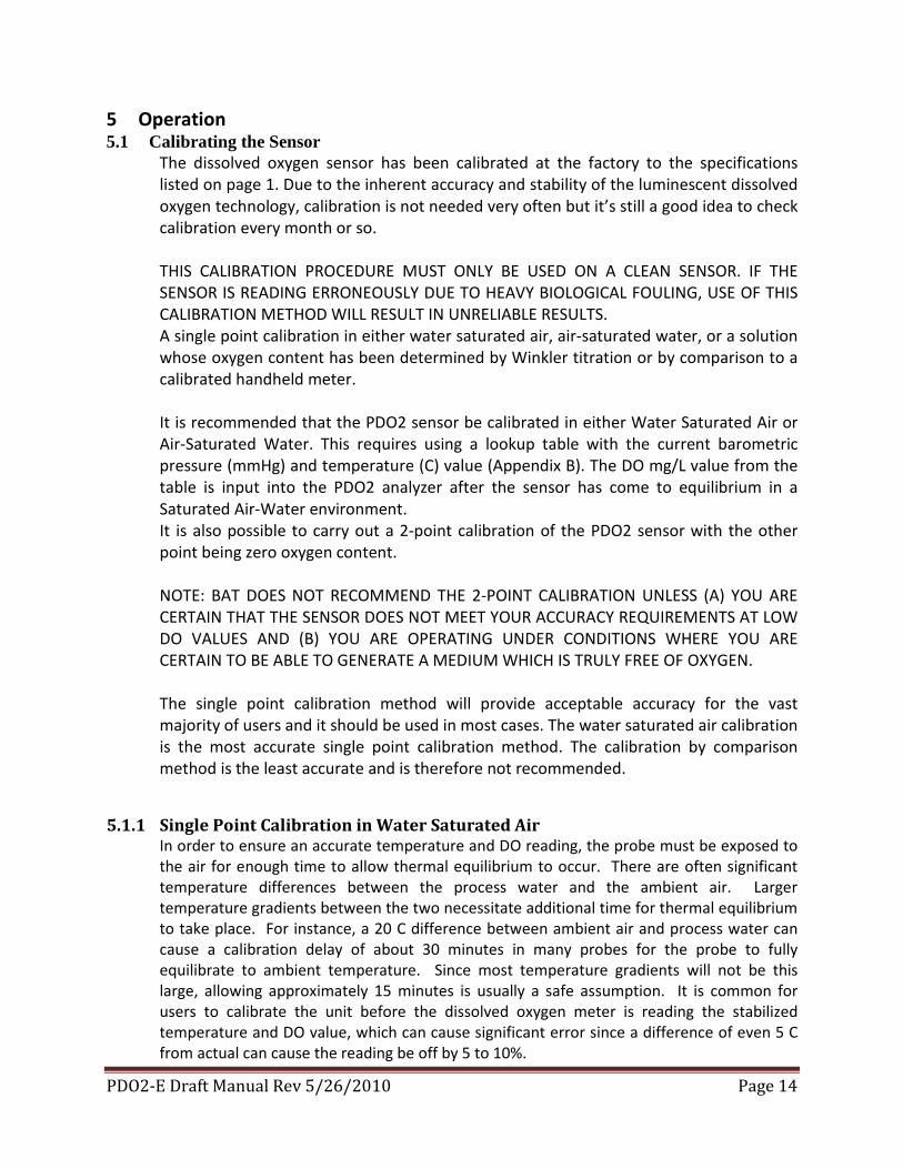
4.3.2 CALIB. LEVEL The 1401DO Analyzer comes preconfigured for a single point calibration (FINAL VALUE). Depending on the operating mode configured in the Basic Settings menu, one or more of the following calibration options will be available:
Here is where the user can select more than just the calibration routine that is assigned to the CAL button. The ZERO POINT and 2-POINT CALIB features are locked by default.
4.3.3 CALIB. LOGBOOK This menu item displays the calculated slope constants for the last five calibration events.
4.3.4 DEVICE INFO This menu item shows the 1401DO input settings from the oxygen sensor.
ZERO POINT FINAL VALUE > 2-POINT CALIB.
PDO2-E Draft Manual Rev 5/26/2010 Page 14
5 Operation 5.1 Calibrating the Sensor
The dissolved oxygen sensor has been calibrated at the factory to the specifications listed on page 1. Due to the inherent accuracy and stability of the luminescent dissolved oxygen technology, calibration is not needed very often but it’s still a good idea to check calibration every month or so. THIS CALIBRATION PROCEDURE MUST ONLY BE USED ON A CLEAN SENSOR. IF THE SENSOR IS READING ERRONEOUSLY DUE TO HEAVY BIOLOGICAL FOULING, USE OF THIS CALIBRATION METHOD WILL RESULT IN UNRELIABLE RESULTS. A single point calibration in either water saturated air, air-saturated water, or a solution whose oxygen content has been determined by Winkler titration or by comparison to a calibrated handheld meter. It is recommended that the PDO2 sensor be calibrated in either Water Saturated Air or Air-Saturated Water. This requires using a lookup table with the current barometric pressure (mmHg) and temperature (C) value (Appendix B). The DO mg/L value from the table is input into the PDO2 analyzer after the sensor has come to equilibrium in a Saturated Air-Water environment. It is also possible to carry out a 2-point calibration of the PDO2 sensor with the other point being zero oxygen content. NOTE: BAT DOES NOT RECOMMEND THE 2-POINT CALIBRATION UNLESS (A) YOU ARE CERTAIN THAT THE SENSOR DOES NOT MEET YOUR ACCURACY REQUIREMENTS AT LOW DO VALUES AND (B) YOU ARE OPERATING UNDER CONDITIONS WHERE YOU ARE CERTAIN TO BE ABLE TO GENERATE A MEDIUM WHICH IS TRULY FREE OF OXYGEN. The single point calibration method will provide acceptable accuracy for the vast majority of users and it should be used in most cases. The water saturated air calibration is the most accurate single point calibration method. The calibration by comparison method is the least accurate and is therefore not recommended.
5.1.1 Single Point Calibration in Water Saturated Air In order to ensure an accurate temperature and DO reading, the probe must be exposed to the air for enough time to allow thermal equilibrium to occur. There are often significant temperature differences between the process water and the ambient air. Larger temperature gradients between the two necessitate additional time for thermal equilibrium to take place. For instance, a 20 C difference between ambient air and process water can cause a calibration delay of about 30 minutes in many probes for the probe to fully equilibrate to ambient temperature. Since most temperature gradients will not be this large, allowing approximately 15 minutes is usually a safe assumption. It is common for users to calibrate the unit before the dissolved oxygen meter is reading the stabilized temperature and DO value, which can cause significant error since a difference of even 5 C from actual can cause the reading be off by 5 to 10%.
PDO2-E Draft Manual Rev 5/26/2010 Page 15
A solution of known dissolved oxygen content, other than 0%, should be used for the gain calibration. The most practical method is to create a Water Saturated Air environment. This can be done by placing a little water on the cotton that comes in the protective plastic cap that ships with the sensor. Place the cap on the sensor making sure that the making sure the luminophore surface does not have droplets of water on it. After around 15 minutes, the air can be assumed to be fully saturated water. An approximate dissolved oxygen saturation value can be found by altitude. Look up your altitude in feet or meters from the Altitude to Atmospheric Pressure Conversion Table in (Appendix A). Find the altitude corrected atmospheric pressure in mmHg. Then look up the mmHg and temperature values in the Solubility of Oxygen at Various Temperatures and Pressures (Appendix B). It is preferable to use the actual local barometric pressure and temperature with (Appendix B) to get the most accurate dissolved oxygen content of Water Saturated Air or an Air Saturated Water Sample. Alternatively an Air Saturated Water Sample is easily created by fully aerating a water sample with an air stone for 15 min. Place the PDO2 sensor in the aerate water and follow the basic procedure below.
Water Saturated Air Calibration Procedure: 1) Power up the PDO2 sensor and Analyzer. 2) Place the protective plastic cap with damp cotton on the PDO2 sensor, making sure the
luminophore surface does not have droplets of water on it. Allow the sensor to equilibrate for at least 15 minutes.
3) Once the measurements have stabilized, press the “CAL” button in the main
MEASURING window to open the Calibration window. “FINAL VALUE>” will be displayed on the screen. Press the “PGM” button twice to get into the calibration entry mode.
4) Use the UP or DOWN arrows to enter the pressure/temperature corrected dissolved
oxygen value in from the lookup table (Appendix B). Press the “PGM” button to enter this value. The calibration SLOPE value will be displayed. Press the “PGM” button again to return to the MEASURING mode.
6 Maintenance 6.1 Routine Maintenance
Periodic maintenance remains good practice. Luminescent dissolved oxygen Sensor technology is more stable than membrane-covered sensors, it’s still a good idea to check calibration every month or so. As with all instruments, it is good operating practice to make regular checks on the quality of data being generated by the PDO2. This can be carried out on site, using one of the following two methods:
PDO2-E Draft Manual Rev 5/26/2010 Page 16
1. Place a recently calibrated transportable dissolved oxygen sensor next to the PDO2 and compare the measurements. It is important to allow a sufficient period of time for temperature equilibration to occur.
2. Place the PDO2 in a solution of known dissolved oxygen content. A solution of 0% dissolved
oxygen saturation can be created by adding a few teaspoons of sodium sulfite to 1 quart of distilled or fresh tap water.
The PDO2 can tolerate some biofouling, however where possible steps should be taken to minimize this; for example shielding the PDO2 sensor from light can reduce the amount of bio-growth.
6.2 Cleaning the Sensor
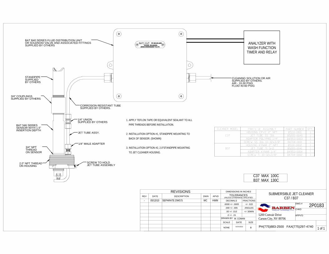
BAT highly recommends the use of our automatic Jet Cleaner System. Refer to drawing (2P0183) Submersible Jet Cleaner for details. Visually inspect the sensor cap. Periodically it may be necessary to clean the PDO2 optical window, to remove bio-growth or other accumulated deposits. Use optical tissue or a cotton swab with soapy water to clean the sensor cap. Rinse with fresh water. DO NOT use a brush or any object that may scratch or damage the optical window.
6.3 Changing the Sensor Cap
Unscrew the old sensor cap from the shaft. Examine the small O-ring that seals the sensor cap to the sensor shaft. Exchange the O-ring, if any traces of wear are seen. A replacement O-ring is included with each replacement sensor cap. Screw the new sensor cap onto the sensor shaft again. Examine the measurement values of the sensor in air, and if necessary, in an oxygen-free medium. If the measurement values deviate significantly from operated value, perform a calibration.

PDO2-E Draft Manual Rev 5/26/2010 Page 17
7 Troubleshooting 7.1 Error Codes 7.2 Warnings
PDO2-E Draft Manual Rev 5/26/2010 Page 18
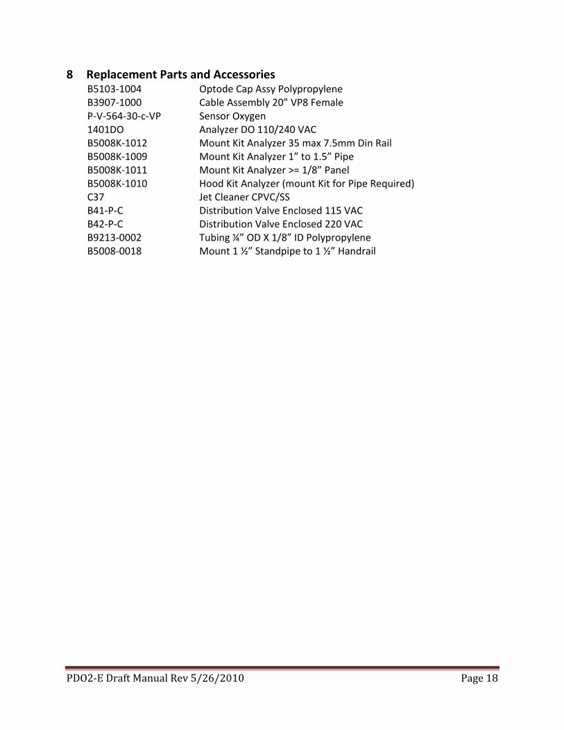
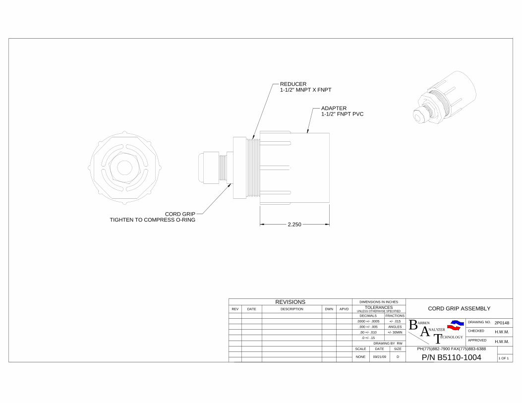
8 Replacement Parts and Accessories B5103-1004 Optode Cap Assy Polypropylene B3907-1000 Cable Assembly 20” VP8 Female P-V-564-30-c-VP Sensor Oxygen 1401DO Analyzer DO 110/240 VAC B5008K-1012 Mount Kit Analyzer 35 max 7.5mm Din Rail B5008K-1009 Mount Kit Analyzer 1” to 1.5” Pipe B5008K-1011 Mount Kit Analyzer >= 1/8” Panel B5008K-1010 Hood Kit Analyzer (mount Kit for Pipe Required) C37 Jet Cleaner CPVC/SS B41-P-C Distribution Valve Enclosed 115 VAC B42-P-C Distribution Valve Enclosed 220 VAC B9213-0002 Tubing ¼” OD X 1/8” ID Polypropylene B5008-0018 Mount 1 ½” Standpipe to 1 ½” Handrail
PDO2-E Draft Manual Rev 5/26/2010 Page 19
9 Terms 9.1 Pricing
All pricing will be per current price list, as stated or modified in specific quotations provided by BAT LLC to the buyer, Distributor, or agent. Prices are subject to change without notice.
9.2 Payment Terms Payment is due on delivery. Open account billing may be assigned at the discretion of BAT LLC, which such accounts due 30 days from invoice. No prompt payment discounts are allowed. Late fees will be assessed at the rate of 1-1/2% per month on unpaid balances, or such other rates as allowed and limited by state and federal laws. Payment terms may be stated or modified in specific quotations provided by BAT LLC to the buyer, distributor or agent.
9.3 Freight
All shipments are FOB Carson City, NV. Freight may be allowed on specific orders as stated in specific quotations or terms of distribution agreed and assigned to specific buyers, distributors, or agents.
9.4 Returns
All returns require a Return Material Authorization (RMA) prior to return, which may be obtained by contacting our office via telephone, email, fax, or postal service. All returned products must be shipped freight pre-paid. Collect shipments and shipments without an RMA will not be accepted.
9.5 Limited Warranty
BAT products are warranted against manufacturing or material defects for 1 year from date of purchase, and must be inspected upon receipt to insure that no visible defects exist. No length of service warranty is provided, as service life is dependent upon the chemistry of the process, and the user’s operating practices. Probes that fail to function upon installation should be returned via an RMA for inspection by BAT.
PDO2-E Draft Manual Rev 5/26/2010 Page 20
10 Drawings: 2P0147 Sensor 2P0148 Mount pipe assy 2P0167 PDO2 O&M 2P0183 Submersible Jet Cleaner
PDO2-E Draft Manual Rev 5/26/2010 Page 21
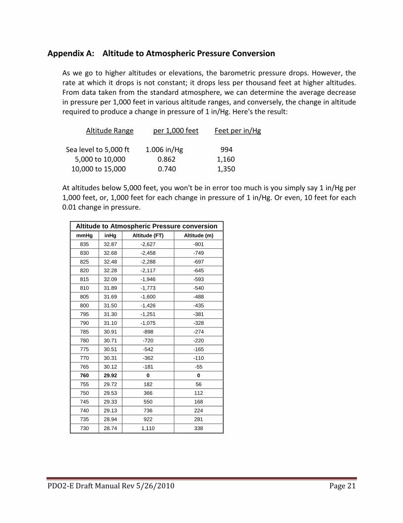
Appendix A: Altitude to Atmospheric Pressure Conversion
As we go to higher altitudes or elevations, the barometric pressure drops. However, the rate at which it drops is not constant; it drops less per thousand feet at higher altitudes. From data taken from the standard atmosphere, we can determine the average decrease in pressure per 1,000 feet in various altitude ranges, and conversely, the change in altitude required to produce a change in pressure of 1 in/Hg. Here's the result:
Altitude Range per 1,000 feet Feet per in/Hg
Sea level to 5,000 ft 1.006 in/Hg 994 5,000 to 10,000 0.862 1,160 10,000 to 15,000 0.740 1,350
At altitudes below 5,000 feet, you won't be in error too much is you simply say 1 in/Hg per 1,000 feet, or, 1,000 feet for each change in pressure of 1 in/Hg. Or even, 10 feet for each 0.01 change in pressure.
Altitude to Atmospheric Pressure conversion mmHg inHg Altitude (FT) Altitude (m)
835 32.87 -2,627 -801
830 32.68 -2,458 -749
825 32.48 -2,288 -697
820 32.28 -2,117 -645
815 32.09 -1,946 -593
810 31.89 -1,773 -540
805 31.69 -1,600 -488
800 31.50 -1,426 -435
795 31.30 -1,251 -381
790 31.10 -1,075 -328
785 30.91 -898 -274
780 30.71 -720 -220
775 30.51 -542 -165
770 30.31 -362 -110
765 30.12 -181 -55
760 29.92 0 0 755 29.72 182 56
750 29.53 366 112
745 29.33 550 168
740 29.13 736 224
735 28.94 922 281
730 28.74 1,110 338
PDO2-E Draft Manual Rev 5/26/2010 Page 22
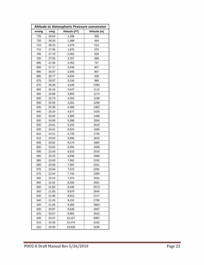
Altitude to Atmospheric Pressure conversion mmHg inHg Altitude (FT) Altitude (m)
725 28.54 1,298 396
720 28.35 1,488 454
715 28.15 1,679 512
710 27.95 1,870 570
705 27.76 2,063 629
700 27.56 2,257 688
695 27.36 2,452 747
690 27.17 2,648 807
685 26.97 2,846 867
680 26.77 3,044 928
675 26.57 3,244 989
670 26.38 3,445 1050
665 26.18 3,647 1112
660 25.98 3,850 1174
655 25.79 4,055 1236
650 25.59 4,261 1299
645 25.39 4,468 1362
640 25.20 4,677 1425
635 25.00 4,886 1489
630 24.80 5,098 1554
625 24.61 5,310 1619
620 24.41 5,524 1684
615 24.21 5,739 1749
610 24.02 5,956 1815
605 23.82 6,174 1882
600 23.62 6,394 1949
595 23.43 6,615 2016
590 23.23 6,838 2084
585 23.03 7,062 2152
580 22.83 7,287 2221
575 22.64 7,515 2291
570 22.44 7,744 2360
565 22.24 7,974 2431
560 22.05 8,206 2501
555 21.85 8,440 2573
550 21.65 8,676 2644
545 21.46 8,913 2717
540 21.26 9,152 2790
535 21.06 9,393 2863
530 20.87 9,636 2937
525 20.67 9,881 3012
520 20.47 10,127 3087
515 20.28 10,375 3162
510 20.08 10,626 3239
PDO2-E Draft Manual Rev 5/26/2010 Page 23
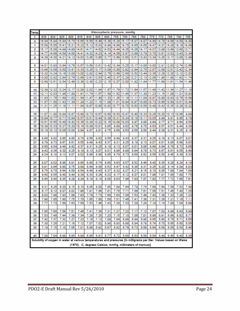
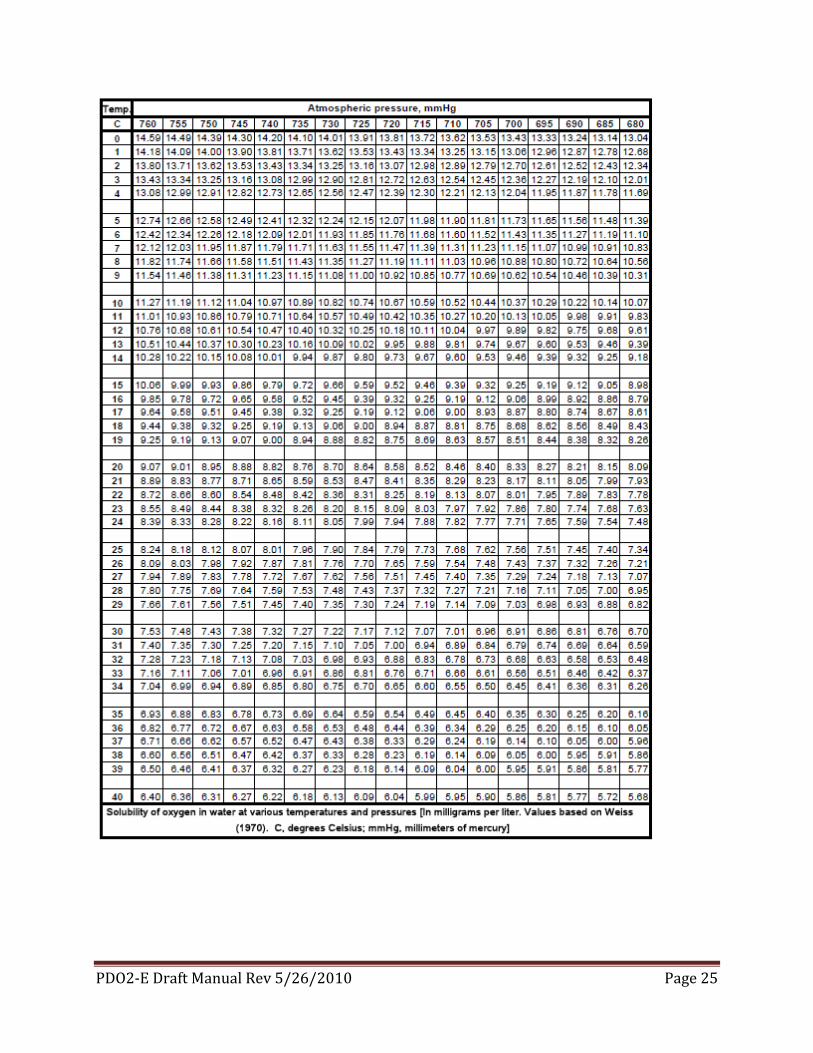
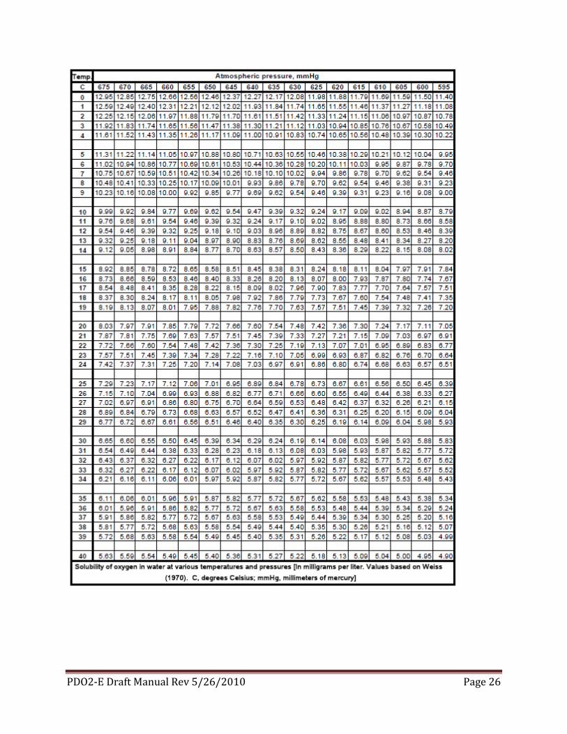
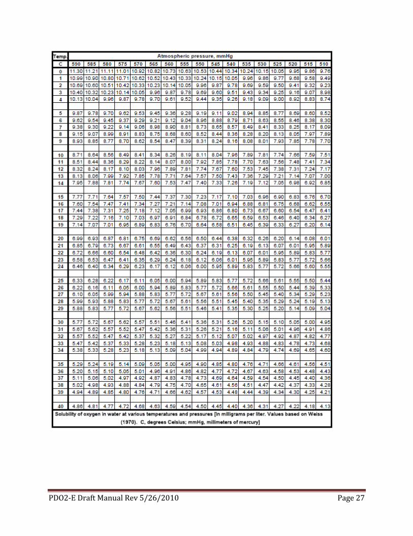
Appendix B: Solubility of Oxygen at Various Temperatures and Pressures
The tables below were generated from the equations of Weiss (1970) and can be customized to cover the range and decimal places needed (see U.S. Geological Survey Quality of Water Branch Technical Memorandum 81.11, 1981). Interactive software to generate a specific range of oxygen-solubility and salinity correction factors can be accessed at: http://water.usgs.gov/software/dotables.html
PDO2-E Draft Manual Rev 5/26/2010 Page 24
PDO2-E Draft Manual Rev 5/26/2010 Page 25
PDO2-E Draft Manual Rev 5/26/2010 Page 26
PDO2-E Draft Manual Rev 5/26/2010 Page 27
ECHNOLOGYTNALYZERA
ARBENBUNLESS OTHERWISE SPECIFIED OPTICAL DO SENSOR
2P0147
PH(775)882-7900 FAX(775)883-6388
TOLERANCESREVISIONS
REV DATE DESCRIPTION DWN APVD
.0 +/- .15
.00 +/- .010
.000 +/- .005.0000 +/- .0005
+/- 30MIN
ANGLES+/- .015
FRACTIONSDECIMALS
DIMENSIONS IN INCHES
D09/21/09NONE
DRAWING BY RWSIZESCALE DATE
1 OF 1
APPROVED
CHECKED
DRAWING NO.
H.W.M.
H.W.M.
8.9"
REPLACEABLE OPTICAL NOSE POLYPROPYLENE OR KYNAR WITHEPDM OR VITON SEALS
.865 O
1-1/2"3/4" NPT THREAD
POLYPROPYLENE OR KYNAR BODY EPDM OR VITON INTERNAL SEALS
NYLON CORD GRIP
3/4" NPT THREAD
30 FT. CABLE STANDARD / CUSTOM LENGTHS AVAILABLE
SILICONE PROTECTED LUMINOPHORE(DO NOT TOUCH OR SCRATCH SURFACE)
ADJUSTABLECORD GRIP ASSEMBLY
PVC
4-1/4" VP8 MALE CONNECTOR
4"
1-1/2" NPT THREAD
1.05 O
RATINGS
-10 TO 80 C
POLYPRO -15 TO 100 PSIG KYNAR -15 TO 150 PSIG
POLYURETHANE CABLE
FINGER TIGHTEN THREADSONLY
SLIP FOR CUSTOMERS1-1/2" STAND PIPE
ECHNOLOGYTNALYZERA
ARBENBUNLESS OTHERWISE SPECIFIED CORD GRIP ASSEMBLY
2P0148
PH(775)882-7900 FAX(775)883-6388
TOLERANCESREVISIONS
REV DATE DESCRIPTION DWN APVD
.0 +/- .15
.00 +/- .010
.000 +/- .005.0000 +/- .0005
+/- 30MIN
ANGLES+/- .015
FRACTIONSDECIMALS
DIMENSIONS IN INCHES
D09/21/09NONE
DRAWING BY RWSIZESCALE DATE
1 OF 1
APPROVED
CHECKED
DRAWING NO.
H.W.M.
H.W.M.
P/N B5110-1004
CORD GRIPTIGHTEN TO COMPRESS O-RING
ADAPTER1-1/2" FNPT PVC
REDUCER1-1/2" MNPT X FNPT
2.250
UNLESS OTHERWISE SPECIFIEDTOLERANCES
REVISIONSREV DATE DESCRIPTION DWN APVD
.0 +/- .15
.00 +/- .010
.000 +/- .005.0000 +/- .0005
+/- 30MIN
ANGLES+/- .015
FRACTIONSDECIMALS
DIMENSIONS IN INCHES
ANONE
DRAWN BY
SIZESCALE DATE
APPROVED
CHECKED
DRAWING NO.
PH(775)883-2500 FAX(775)297-4740
5200 Convair DriveCarson City, NV 89706
1-1/2" PVC PIPE(CUSTOMER SUPPLIED)
MALE VP8CONNECTOR
A
1"
CORD GRIP ASSEMBLYB5110-1004(INCLUDED WITH SENSOR)
BRACKET1-1/2" PIPE MT
B5008-001820" VP8 FEMALECABLE ASSEMBLYP/N B3907-1000
CUSTOMER'SHAND RAIL
APPROX.45°
APPROX.45°
SET SCREWS(2 TYP)
SET SCREWS(2 TYP)
DETAIL A
1/4" HOLE (TYP)1.5FT SPACINGALONG PIPE LENGTH
CONNECTION TERMINALROW 2 #4 BLACK (COAX SHIELD)GND SCREW YELLOW / GREEN
ANODESHIELD
PDO2 BAT DO SENSORS
ROW 1 #15 RED COAX SHIELDROW 1 #14 RED COAX CORE
-24VDC+24VDC
CABLE TO 1401DO ENCLOSURE
FEMALE VP8 CONNECTOR
1 OF 3
DRAWN: W. COWAN
03/22/2010
2P0167
PDO2 DO SENSOR CUSTOMERCONNECTION
A 05/24/10 Correct Views -Add Conn. Details WC TM - 03/22/10 Initial Release WC HWM
UNLESS OTHERWISE SPECIFIEDTOLERANCES
REVISIONSREV DATE DESCRIPTION DWN APVD
.0 +/- .15
.00 +/- .010
.000 +/- .005.0000 +/- .0005
+/- 30MIN
ANGLES+/- .015
FRACTIONSDECIMALS
DIMENSIONS IN INCHES
ANONE
DRAWN BY
SIZESCALE DATE
APPROVED
CHECKED
DRAWING NO.
PH(775)883-2500 FAX(775)297-4740
5200 Convair DriveCarson City, NV 89706
CONNECTION TERMINALROW 2 #4 BLACK (COAX SHIELD)GND SCREW YELLOW / GREEN
ANODESHIELD
PDO2 BAT DO SENSORS
ROW 1 #15 RED COAX SHIELDROW 1 #14 RED COAX CORE
-24VDC+24VDC
GROUND SCREWON UNIT BOX
BLACK COAX SHIELD
RED COAX CORE
RED COAX SHIELD
GREEN 5 PIN HEADER
GREEN 4 PIN HEADER
ORANGE 12 PIN HEADER
GREEN 10 PINHEADER
JUMPERGREEN 5 PIN HEADER #14TOORANGE HEADER #5
GREEN/YELLOWGROUND WIRE
FEMALE VP8 CONNECTOR
HEADERS & WIRING CONNECTIONSWITHIN 1401DO CONTROLLER
NL
1LL+-( () )
ENCLOSURECORD GRIP
TO FEMALEVP8 CONNECTOR
ROW 1
ROW 2ROW 1
ROW 2
JUMPER
ENCLOSURECORD GRIP
2 OF 303/22/2010
2P0167
PDO2 DO SENSOR CUSTOMERCONNECTION - 03/22/10 Initial Release WC HWM
SIDE VIEW1401DO
A 05/24/10 Correct Views -Add Conn. Details WC TM
UNLESS OTHERWISE SPECIFIEDTOLERANCES
REVISIONSREV DATE DESCRIPTION DWN APVD
.0 +/- .15
.00 +/- .010
.000 +/- .005.0000 +/- .0005
+/- 30MIN
ANGLES+/- .015
FRACTIONSDECIMALS
DIMENSIONS IN INCHES
ANONE
DRAWN BY
SIZESCALE DATE
APPROVED
CHECKED
DRAWING NO.
PH(775)883-2500 FAX(775)297-4740
5200 Convair DriveCarson City, NV 89706
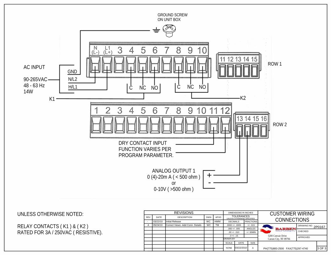
ROW 1
ROW 2
GROUND SCREWON UNIT BOX
N/L2H/L1
AC INPUT
90-265VAC48 - 63 Hz14W
C NC NO
K1
C NC NO
K2
UNLESS OTHERWISE NOTED:
RELAY CONTACTS ( K1 ) & ( K2 )RATED FOR 3A / 250VAC ( RESISTIVE).
GND
CUSTOMER WIRINGCONNECTIONS
DRY CONTACT INPUTFUNCTION VARIES PERPROGRAM PARAMETER.
+-
ANALOG OUTPUT 10 (4)-20m A ( < 500 ohm )
or0-10V ( >500 ohm )
3 OF 303/22/2010
2P0167
- 03/22/10 Initial Release WC HWM A 05/24/10 Correct Views -Add Conn. Details WC TM
UNLESS OTHERWISE SPECIFIEDTOLERANCES
REVISIONSREV DATE DESCRIPTION DWN APVD
.0 +/- .15
.00 +/- .010
.000 +/- .005
.0000 +/- .0005
+/- 30MIN
ANGLES
+/- .015
FRACTIONSDECIMALS
DIMENSIONS IN INCHES
BNONE
DRAWN BY
SIZESCALE DATE
APPV'D
CHKD
DWG #
PH(775)883-2500 FAX(775)297-4740
5200 Convair DriveCarson City, NV 89706
1 of 1
SUBMERSIBLE JET CLEANERC37 / B37
2P0183 - 05/13/10 SEPARATE DWG'S WC HWM
W. COWAN
XX/XX/2010
STANDPIPESUPPLIEDBY OTHERS
1/4" UNIONSUPPLIED BY OTHERS
3/4" COUPLINGSSUPPLIED BY OTHERS
BAT 546 SERIESSENSOR WITH 1.5"INSERTION DEPTH
3/4" NPTTHREADON SENSOR
2.0" NPT THREADON HOUSING
1/4" MALE ADAPTER
JET TUBE ASSY.
CORROSION RESISTANT TUBESUPPLIED BY OTHERS.
CLEANING SOLUTION OR AIRSUPPLIED BY OTHERS.AIR - 10-30 PSIGFLUID 40-60 PSIG
CLEANER MODEL
C37
B37
ANALYZER WITHWASH FUNCTION
TIMER AND RELAY
PARTS OF ASSEMBLY
HOUSING CPVC 2" NPT
JET TUBE SS 316
ADAPTER POLYPRO 1/4"
SCREW SS 316 10-32x3/8"
HOUSING KYNAR 2" NPT
JET TUBE Ti Gr2
ADAPTER KYNAR 1/4"
SCREW Ti 10-32x3/8"
1. APPLY TEFLON TAPE OR EQUIVALENT SEALANT TO ALL PIPE THREADS BEFORE INSTALLATION.
2. INSTALLATION OPTION #1, STANDPIPE MOUNTING TO BACK OF SENSOR. (SHOWN)
3. INSTALLATION OPTION #2, 2.0"STANDPIPE MOUNTING TO JET CLEANER HOUSING.
C37 MAX 100CB37 MAX 130C
PART NUMBER
B5110-0001
B5205-0040
B4953-0003
B4704-0001
B5110-0002
B5205-0041
B4953-0004
B4704-0002
QTY.
1
1
1
1
1
1
1
1
BAT B40 SERIES FLUID DISTRIBUTION UNITOR SOLENOID VALVE AND ASSOCIATED FITTINGSSUPPLIED BY OTHERS
SCREW TO HOLD JET TUBE ASSEMBLY