47' MLB information
27
47’ MLB By: BM1 Frank E Wink Physical Information: Hull Length Length Overall Hull Beam Beam Overall Freeboard Bow Amidships Aft Draft Highest Points: Fixed Unfixed Engines Rated Horsepower Reduction Gear Fuel Type Fuel Capacity 100% 95% (usable) Electrical Generation Propellers Hoisting condition (boat, full fuel, outfit; no crew or cargo) Trailer Information Potable Water Capacity 47’11” 48’11” (w/ rubrails) 14’0” (w/o rubrails) 15’0” (w/ rubrails) 6’8” 2’2” (Deck Recess) 7’1” 4’6” 18’6” (Radar antenna) 28’4” (HF antenna) Twin Detroit Diesel Electronically Controlled (DDEC) 6V92TA 435 BHP at 2100 RPM Reintjes WVS 234 UP, 2:1 reduction Diesel 394 GAL 373 GAL Dual Alternators Fixed 4 bladed, 28” diameter, 36” pitch 40,000 LBS The 47FT MLB was not designed for transport on a boat trailer. Over-the-road delivery should be performed by a licensed commercial shipping company. 5 GAL
Transcript of 47' MLB information
47’ MLB By: BM1 Frank E Wink
Physical Information: Hull Length Length Overall Hull Beam Beam Overall Freeboard Bow Amidships Aft Draft Highest Points: Fixed Unfixed Engines Rated Horsepower Reduction Gear Fuel Type Fuel Capacity 100% 95% (usable) Electrical Generation Propellers Hoisting condition (boat, full fuel, outfit; no crew or cargo) Trailer Information Potable Water Capacity
47’11” 48’11” (w/ rubrails) 14’0” (w/o rubrails) 15’0” (w/ rubrails) 6’8” 2’2” (Deck Recess) 7’1” 4’6” 18’6” (Radar antenna) 28’4” (HF antenna) Twin Detroit Diesel Electronically Controlled (DDEC) 6V92TA 435 BHP at 2100 RPM Reintjes WVS 234 UP, 2:1 reduction Diesel 394 GAL 373 GAL Dual Alternators Fixed 4 bladed, 28” diameter, 36” pitch 40,000 LBS The 47FT MLB was not designed for transport on a boat trailer. Over-the-road delivery should be performed by a licensed commercial shipping company. 5 GAL
Hull Construction Compartments: 5456 Marine Grade Aluminum Lazarette; Transom to 1 Side Shell; ¼” Engine Room; 1 to 5 Bottom; 5/16” Survivors; 5 to 8 Chine Plates; 3/8” Aux: 8 to 10 Keel; ½” Forward ; 10 to 15 Forepeak; 15 to Bow Enclosed Bridge 8 to 10 above Main Deck Modified planing hull design with a deep V planing from bow to stern Longitudinal Frame Spacing 11” + or - Transversal Frame Spacing 30” + or – Vents: Securable: (Y/N): Forepeak 2” Checkball N Forward Compt. Dorade w/ 2” CB Y Aux. Mach Space Forced Air N Fuel Tank Vent 2” Checkball N Main Eng. Room Vent Behind Ladder Y P/S Aux. Eng. Room Vents Flaps Y Operational Characteristics: Maximum Personnel (including crew) Maximum Seas Maximum Breaking (Surf) Seas Maximum Winds Range (Cruising RPM in Calm Water) Maximum Operating Distance from Shore Maximum RPM Maximum Speed Cruising RPM Cruising Speed Towing Capacity (with 3 ¼” Towline) Towing Capacity (with 2” Towline) Ice Breaking Capability
34 (180 lbs each) 30’ 20’ 50 KTS 200 NM 50 NM 2100 RPM 25 KTS 1850 RPM 20 KTS 150 Displacement Tons 50 Displacement Tons Light Surface Ice
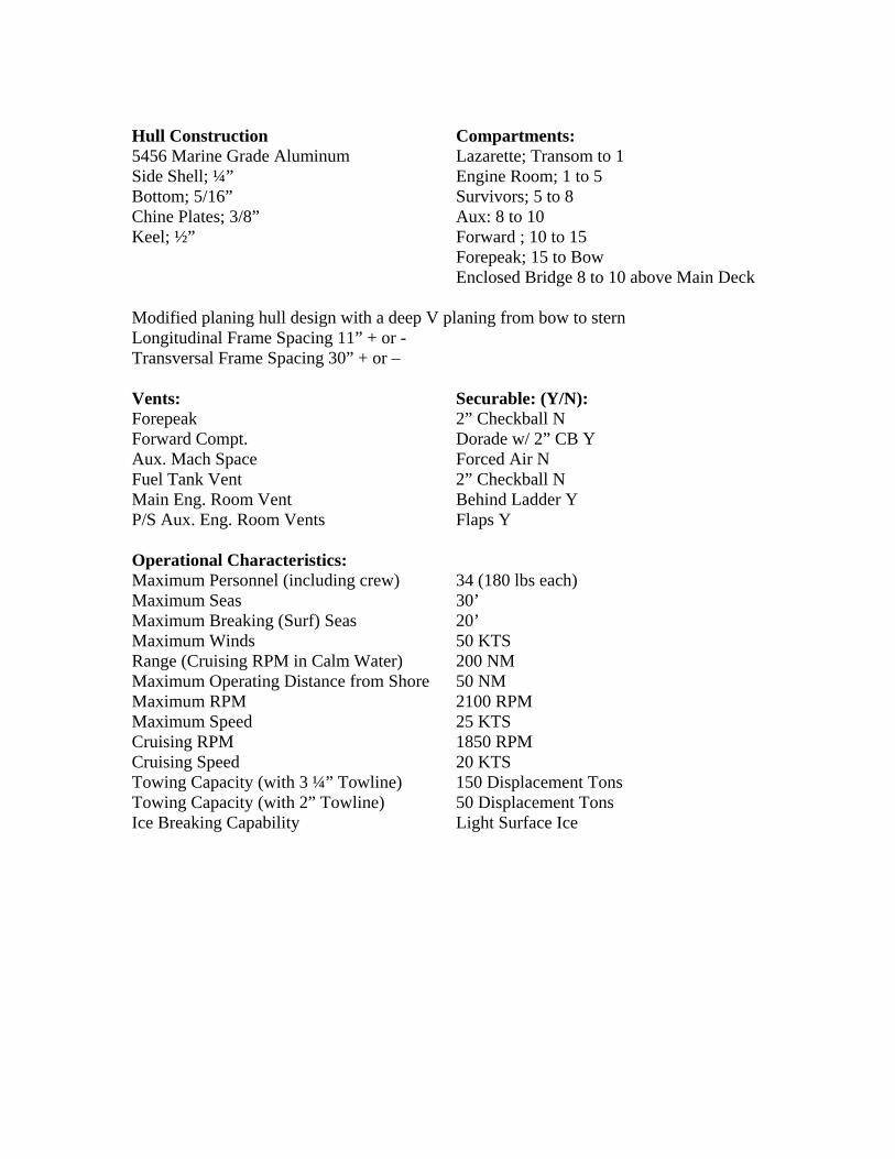
Bilge System: Outfitted with 7 pumps rated for 33gpm. It will require approximately 10" of water in a bilge space to activate the bilge pump when set in the automatic mode. Alarm activates at 5” of water.
Bilge Pumps Discharge Forward Compartment Starboard Aux. Space Port Port Red Gear Port Side w/ Fwd Engine Room Stbd. Red Gear Stbd. Side w/ Aft Engine Room Fwd Engine Room Port Side w/ Fwd Engine Room Aft Engine Room Stbd. Side w/ Aft Engine Room Lazarette Port Transom Towing Equipment Upper Reel: 300’ of 2 ¼ DBN Lower Reel: 900’ of 3 ¼ DBN – Lower reel has electric motor. Both reels can use the hand crank. Anchoring Equipment Line 300’ of 2 ¼” DBN Type 19lb Fortress FX-37 Danforth Chain 9’ of 3/8” Stainless Steel and 3/8” shackles and swivel.
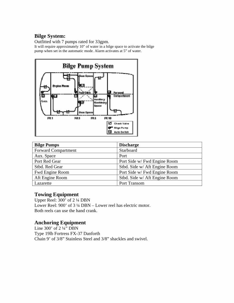
Engines: The 47FT MLB is equipped with two Detroit Diesel Electronically-Controlled (DDEC) 6-cylinder, 2-stroke, turbo-charged, after-cooled marine diesel engines to DDEC 6V92TA. The engine rating is 435 horsepower at 2100 RPM. The engines are separate port and starboard versions; each is right-hand rotating as viewed looking aft from the front of the engine. Coolant capacity is 12 gallons and lubricating oil capacity is 5.5 gallons of 40-weight 2104D. A computer controls all engine combustion functions; it maintains constant engine RPM under variable loads and limits maximum and minimum RPM.
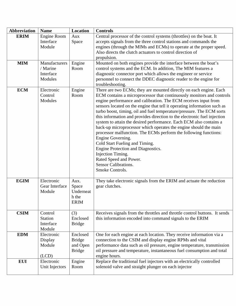
Abbreviation Name Location Controls ERIM Engine Room
Interface Module
Aux Space
Central processor of the control systems (throttles) on the boat. It accepts signals from the three control stations and commands the engines (through the MIMs and ECMs) to operate at the proper speed. Also directs the clutch actuators to control direction of propulsion.
MIM Manufacturers / Marine Interface Modules
Engine Room
Mounted on both engines provide the interface between the boat’s control systems and the ECM. In addition, The MIM features a diagnostic connector port which allows the engineer or service personnel to connect the DDEC diagnostic reader to the engine for troubleshooting.
ECM Electronic Control Modules
Engine Room
There are two ECMs; they are mounted directly on each engine. Each ECM contains a microprocessor that continuously monitors and controls engine performance and calibration. The ECM receives input from sensors located on the engine that tell it operating information such as turbo boost, timing, oil and fuel temperature/pressure. The ECM sorts this information and provides direction to the electronic fuel injection system to attain the desired performance. Each ECM also contains a back-up microprocessor which operates the engine should the main processor malfunction. The ECMs perform the following functions: Engine Governing. Cold Start Fueling and Timing. Engine Protection and Diagnostics. Injection Timing. Rated Speed and Power. Sensor Calibrations. Smoke Controls.
EGIM Electronic Gear Interface Module
Aux. Space Underneath the ERIM
They take electronic signals from the ERIM and actuate the reduction gear clutches.
CSIM Control Station Interface Module
(3) Enclosed Bridge
Receives signals from the throttles and throttle control buttons. It sends this information encoded into command signals to the ERIM
EDM Electronic Display Module (LCD)
Enclosed Bridge and Open Bridge
One for each engine at each location. They receive information via a connection to the CSIM and display engine RPMs and vital performance data such as oil pressure, engine temperature, transmission oil pressure and temperature, instantaneous fuel consumption and total engine hours.
EUI Electronic Unit Injectors
Engine Room
Replace the traditional fuel injectors with an electrically controlled solenoid valve and straight plunger on each injector
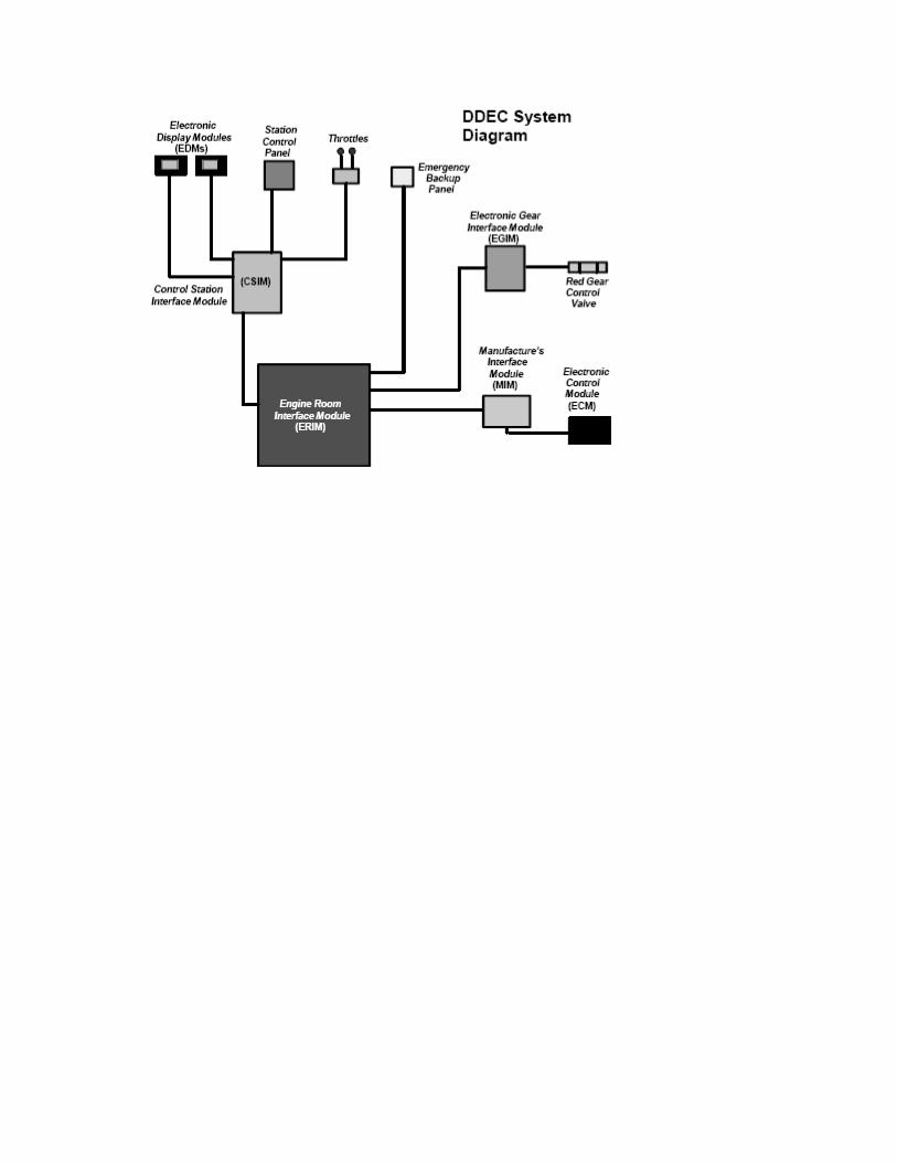
Reduction Gear: The 47FT MLB uses Reintjes WVS 234 UP Marine Reduction gears located in the Survivors compartment to port and starboard of the fuel tank between Frames 6 and 7. The gear is a “U” drive unit where the output and input flanges are on the same side of the gear and parallel. The reduction ratio is 2:1 in forward and reverse. The gear uses 7.1 gallons of 30-weight lubricating oil for clutch-apply pressure and lubrication. A temperature regulating valve and gear oil cooler maintain oil temperatures between 140-176°F. Normal disengaged pressure is 58 to 66 PSI and normal clutch-applied pressure is 230 to 290 PSI. If apply pressure is lost, the gear is fitted with a come-home device. It is engaged by mechanically locking the clutch together with set screws. In the event of electronic control failure, the control valve can be operated manually.
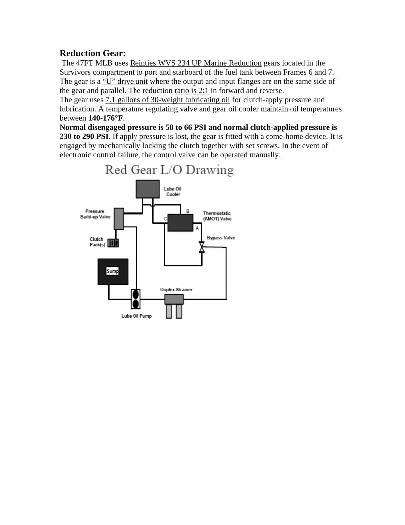
Raw Water Cooling System There are two separate raw water systems on the 47FT MLB. The primary system provides cooling for various elements of the propulsion system. A separate raw water system serves the boat’s HVAC system; The primary raw water system carries out five functions: Maintains fuel oil temperatures below 90°F.
Removes heat from engine coolant to maintain proper operating temperatures. Removes heat from reduction gear lube oil to maintain proper operating temperatures.
Removes heat from the steering system hydraulic oil to maintain proper operating temperatures. Provides cooling and quieting for engine exhaust.
Each raw water valve is located on the opposite side of the keel of the engine Flow that it services between Frames 4 and 5 below the engine room ladder. System Flow: The raw water flows through a 4" duplex strainer on the port and starboard inboard girders between Frames 4 and 5. From the sea strainer, water flows to the raw water pump that has a flow rating of 67 GPM. From the raw water pump, water flows through the fuel cooler and maintains fuel temperature below 90°F. From the fuel cooler, water is piped to the engine heat exchanger where it cools the engine coolant. On the outboard side of each engine, the flow is divided. One direction leads forward through Bulkhead 5 to the reduction gear oil cooler and the shaft seal for sealing and cooling. The second flow is restricted through a 1” restrictor plate and goes to the water-cooled muffler. On the starboard side, a separate branch provides cooling for the steering system hydraulic fluid. After passing through the reduction gear oil cooler, the flow reenters the engine room and branches off. One leg goes to the deicing valve, while the other discharges overboard through the water-cooled muffler. In the water-cooled muffler, raw water cools and quiets the exhaust and is discharged over the side via the exhaust ports. The mufflers are cross-connected to prevent back pressure if one exhaust port is submerged. An isolation valve is installed in the cross-connect to prevent internal condensation in the event of single engine operation.
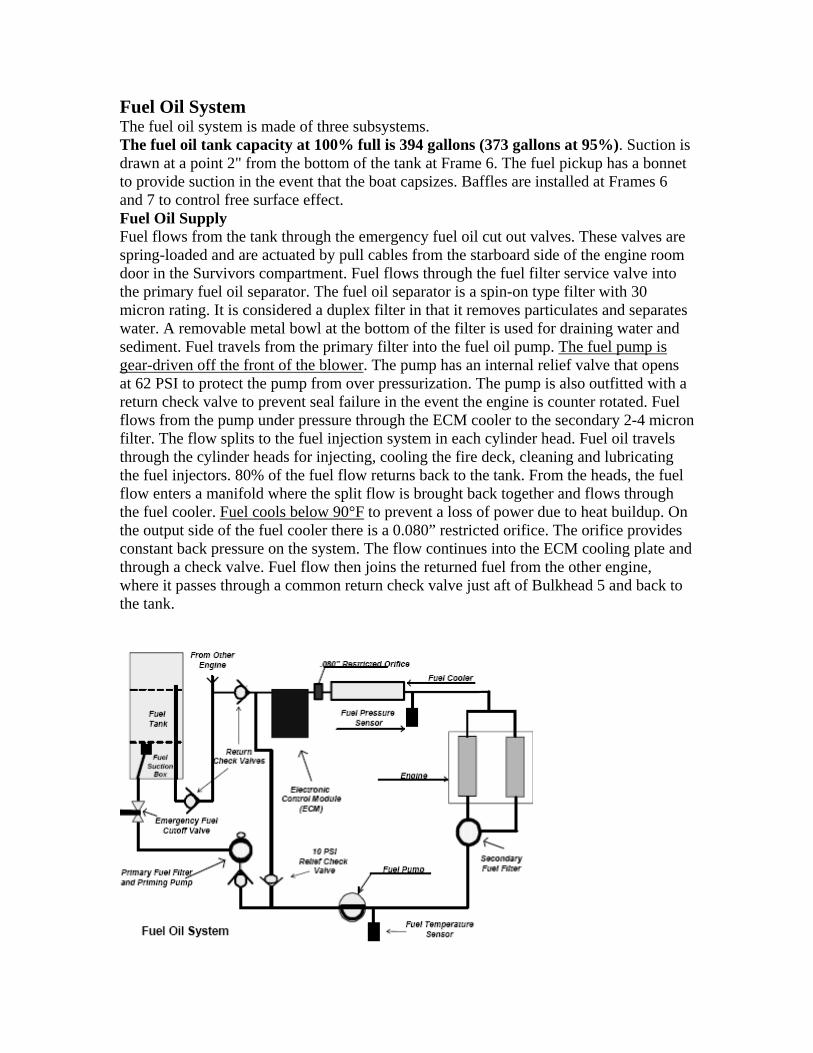
Fuel Oil System The fuel oil system is made of three subsystems. The fuel oil tank capacity at 100% full is 394 gallons (373 gallons at 95%). Suction is drawn at a point 2" from the bottom of the tank at Frame 6. The fuel pickup has a bonnet to provide suction in the event that the boat capsizes. Baffles are installed at Frames 6 and 7 to control free surface effect. Fuel Oil Supply Fuel flows from the tank through the emergency fuel oil cut out valves. These valves are spring-loaded and are actuated by pull cables from the starboard side of the engine room door in the Survivors compartment. Fuel flows through the fuel filter service valve into the primary fuel oil separator. The fuel oil separator is a spin-on type filter with 30 micron rating. It is considered a duplex filter in that it removes particulates and separates water. A removable metal bowl at the bottom of the filter is used for draining water and sediment. Fuel travels from the primary filter into the fuel oil pump. The fuel pump is gear-driven off the front of the blower. The pump has an internal relief valve that opens at 62 PSI to protect the pump from over pressurization. The pump is also outfitted with a return check valve to prevent seal failure in the event the engine is counter rotated. Fuel flows from the pump under pressure through the ECM cooler to the secondary 2-4 micron filter. The flow splits to the fuel injection system in each cylinder head. Fuel oil travels through the cylinder heads for injecting, cooling the fire deck, cleaning and lubricating the fuel injectors. 80% of the fuel flow returns back to the tank. From the heads, the fuel flow enters a manifold where the split flow is brought back together and flows through the fuel cooler. Fuel cools below 90°F to prevent a loss of power due to heat buildup. On the output side of the fuel cooler there is a 0.080” restricted orifice. The orifice provides constant back pressure on the system. The flow continues into the ECM cooling plate and through a check valve. Fuel flow then joins the returned fuel from the other engine, where it passes through a common return check valve just aft of Bulkhead 5 and back to the tank.
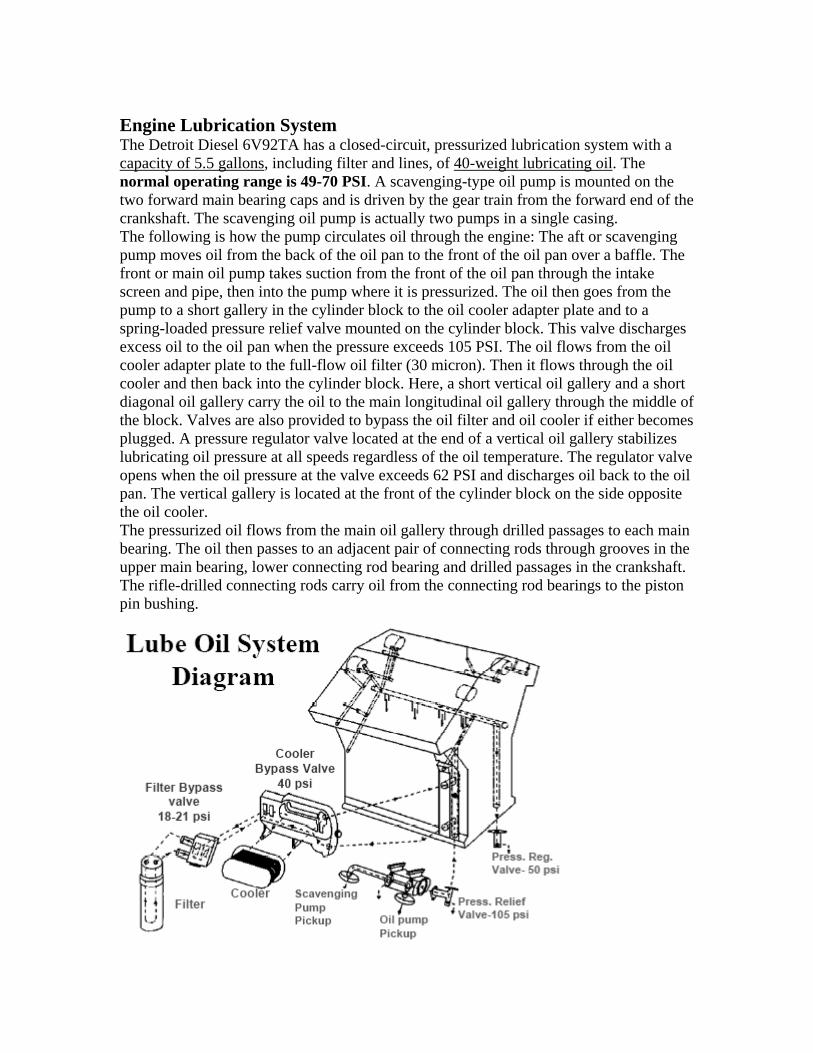
Engine Lubrication System The Detroit Diesel 6V92TA has a closed-circuit, pressurized lubrication system with a capacity of 5.5 gallons, including filter and lines, of 40-weight lubricating oil. The normal operating range is 49-70 PSI. A scavenging-type oil pump is mounted on the two forward main bearing caps and is driven by the gear train from the forward end of the crankshaft. The scavenging oil pump is actually two pumps in a single casing. The following is how the pump circulates oil through the engine: The aft or scavenging pump moves oil from the back of the oil pan to the front of the oil pan over a baffle. The front or main oil pump takes suction from the front of the oil pan through the intake screen and pipe, then into the pump where it is pressurized. The oil then goes from the pump to a short gallery in the cylinder block to the oil cooler adapter plate and to a spring-loaded pressure relief valve mounted on the cylinder block. This valve discharges excess oil to the oil pan when the pressure exceeds 105 PSI. The oil flows from the oil cooler adapter plate to the full-flow oil filter (30 micron). Then it flows through the oil cooler and then back into the cylinder block. Here, a short vertical oil gallery and a short diagonal oil gallery carry the oil to the main longitudinal oil gallery through the middle of the block. Valves are also provided to bypass the oil filter and oil cooler if either becomes plugged. A pressure regulator valve located at the end of a vertical oil gallery stabilizes lubricating oil pressure at all speeds regardless of the oil temperature. The regulator valve opens when the oil pressure at the valve exceeds 62 PSI and discharges oil back to the oil pan. The vertical gallery is located at the front of the cylinder block on the side opposite the oil cooler. The pressurized oil flows from the main oil gallery through drilled passages to each main bearing. The oil then passes to an adjacent pair of connecting rods through grooves in the upper main bearing, lower connecting rod bearing and drilled passages in the crankshaft. The rifle-drilled connecting rods carry oil from the connecting rod bearings to the piston pin bushing.
Hydraulic Steering System The 47FT MLB uses a Manual Servo Steering System that interacts with a power assist system. The steering system uses 2 gallons of Tellus T-15 hydraulic fluid. The manual system serves as the boat’s emergency steering. If the manual system fails, the boat can be steered using the engines. Though interconnected, for ease of understanding, the systems will be discussed individually.
MANUAL + POWER ASSISTED Manual System Operation A helm unit (axial piston pump) on the open starboard steering station displaces 2.3 cubic inches of fluid per revolution. As the wheel is turned, it pumps fluid from one side of the servo ram to the other. The steering fluid reservoir assembly in the engine room provides makeup oil and is closed to the atmosphere. Proper system operation requires a level of ½ - ¾ and a head pressure of 20 to 30 PSI in the reservoir. A gauge at the reservoir displays pressure. The manual steering operates as a standard hydraulic system by supplying oil to either side of servo cylinder assembly in the lazarette. By responding directly to helm movement, the connected rudders move with little effort on the steering wheel. When the jog levers are used, an electronic signal is sent to the control which pumps fluid to the appropriate side of the servo ram. When energized, the autopilot system sends signals to the autopilot pump to control the operation of the servo ram. Power Assisted System Operation The power assist system operates in direct response to the manual steering system to give very high response steering with minimal effort. Two hydraulic pumps driven by the engines provide fluid flow in the power assist system. Fluid flows from the pump to the pump relief/flow control valve that controls system pressure including the manual helm steering circuit. In operation, pressure is only developed in the power circuit to bring about changes in rudder position. Under steady conditions, the power pumps circulate oil freely in the power circuit. The fluid enters the appropriate side of the port and starboard power cylinder in the servo/power cylinder unit in the lazarette. The servo cylinder commands the power cylinder to follow its movement and thus operate in direct response to helm movement. Another important function of this control assembly is that it provides automatic return to manual helm steering if the power pump flow is lost or interrupted. System Reservoir The hydraulic steering system has the reservoir assembly mounted on the starboard shell plating between Frames 2 and 3. It contains 1 gallon of oil and performs the following functions for the system: Supplies oil for the two-engine drive power pumps. A supply of filtered oil for both the helm unit and the autopilot pump assembly. The filter is a 10 micron rated filter. Cooling (from the raw water system) to keep the system operating within operating parameters. Continuous filtering of oil in the power assist circuit.
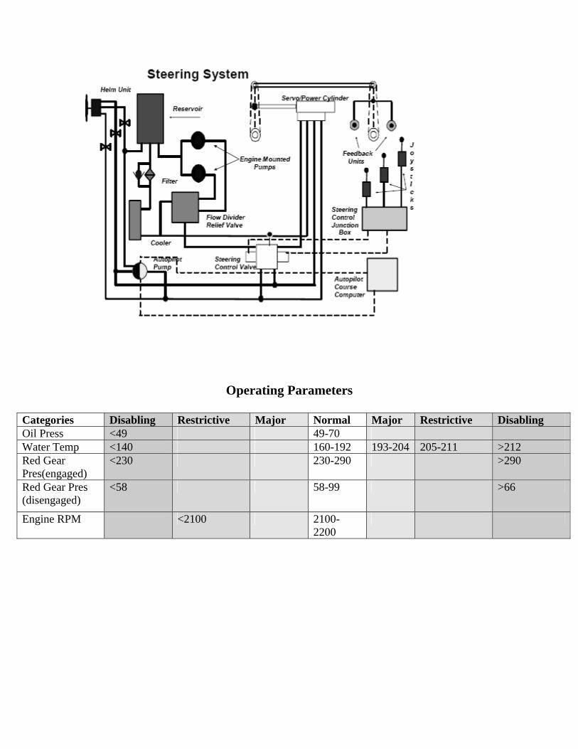
Operating Parameters
Categories Disabling Restrictive Major Normal Major Restrictive Disabling Oil Press <49 49-70 Water Temp <140 160-192 193-204 205-211 >212 Red Gear Pres(engaged)
<230 230-290 >290
Red Gear Pres (disengaged)
<58 58-99 >66
Engine RPM <2100 2100-2200
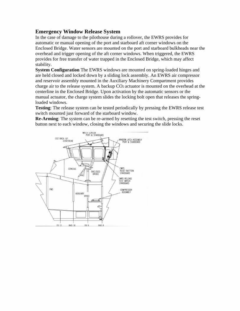
Emergency Window Release System In the case of damage to the pilothouse during a rollover, the EWRS provides for automatic or manual opening of the port and starboard aft corner windows on the Enclosed Bridge. Water sensors are mounted on the port and starboard bulkheads near the overhead and trigger opening of the aft corner windows. When triggered, the EWRS provides for free transfer of water trapped in the Enclosed Bridge, which may affect stability. System Configuration The EWRS windows are mounted on spring-loaded hinges and are held closed and locked down by a sliding lock assembly. An EWRS air compressor and reservoir assembly mounted in the Auxiliary Machinery Compartment provides charge air to the release system. A backup CO2 actuator is mounted on the overhead at the centerline in the Enclosed Bridge. Upon activation by the automatic sensors or the manual actuator, the charge system slides the locking bolt open that releases the spring-loaded windows. Testing: The release system can be tested periodically by pressing the EWRS release test switch mounted just forward of the starboard window. Re-Arming: The system can be re-armed by resetting the test switch, pressing the reset button next to each window, closing the windows and securing the slide locks.
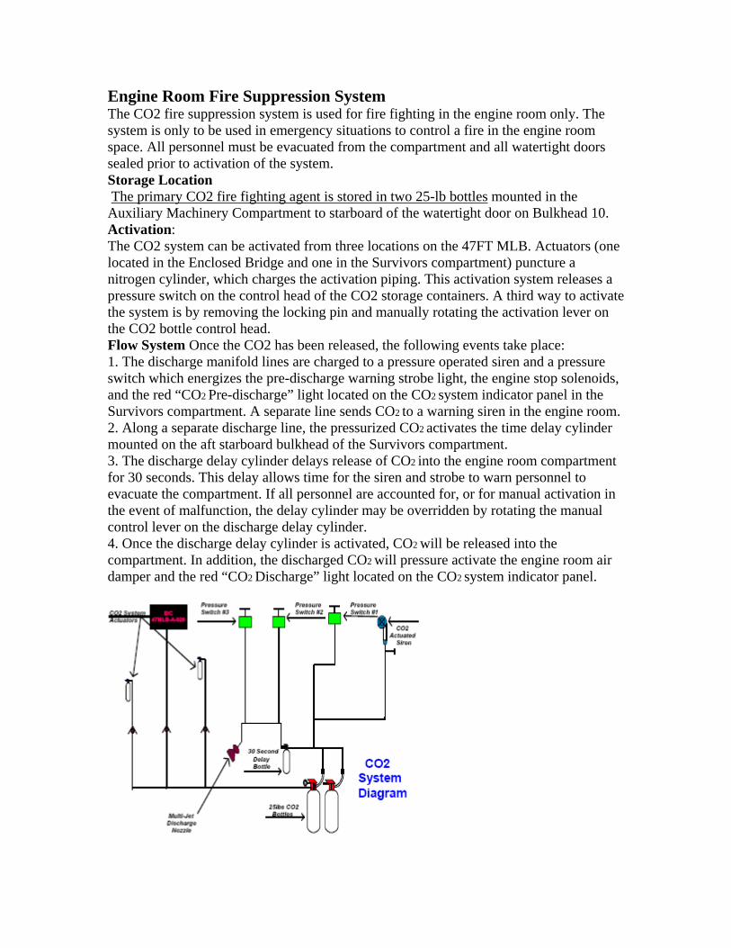
Engine Room Fire Suppression System The CO2 fire suppression system is used for fire fighting in the engine room only. The system is only to be used in emergency situations to control a fire in the engine room space. All personnel must be evacuated from the compartment and all watertight doors sealed prior to activation of the system. Storage Location The primary CO2 fire fighting agent is stored in two 25-lb bottles mounted in the Auxiliary Machinery Compartment to starboard of the watertight door on Bulkhead 10. Activation: The CO2 system can be activated from three locations on the 47FT MLB. Actuators (one located in the Enclosed Bridge and one in the Survivors compartment) puncture a nitrogen cylinder, which charges the activation piping. This activation system releases a pressure switch on the control head of the CO2 storage containers. A third way to activate the system is by removing the locking pin and manually rotating the activation lever on the CO2 bottle control head. Flow System Once the CO2 has been released, the following events take place: 1. The discharge manifold lines are charged to a pressure operated siren and a pressure switch which energizes the pre-discharge warning strobe light, the engine stop solenoids, and the red “CO2 Pre-discharge” light located on the CO2 system indicator panel in the Survivors compartment. A separate line sends CO2 to a warning siren in the engine room. 2. Along a separate discharge line, the pressurized CO2 activates the time delay cylinder mounted on the aft starboard bulkhead of the Survivors compartment. 3. The discharge delay cylinder delays release of CO2 into the engine room compartment for 30 seconds. This delay allows time for the siren and strobe to warn personnel to evacuate the compartment. If all personnel are accounted for, or for manual activation in the event of malfunction, the delay cylinder may be overridden by rotating the manual control lever on the discharge delay cylinder. 4. Once the discharge delay cylinder is activated, CO2 will be released into the compartment. In addition, the discharged CO2 will pressure activate the engine room air damper and the red “CO2 Discharge” light located on the CO2 system indicator panel.
BECCs Capsizing: Once in safe water (A) Check for next wave!! (B) Reacquire Helm and throttle control. 1. Engineer should check for damage 2. Investigate the condition of the engine room by looking through the window in the watertight door. The engine room may be coated with water and oil presenting a fire hazard. 3. Begin de-watering the vessel by energizing all of the installed electric bilge pumps. If the flooding is too severe to be handled by the electric bilge pumps, rig the CG-P6 on the aft deck and connect the suction line to the engine room suction standpipe. 4. Once dewatering is complete, check the oil in both main engines (Engines must be secured to ensure an accurate reading). Add oil as necessary. 5. Closely check the material results to the coxswain. 6. After damage has been assessed, determine whether it is proceed with the mission or should you return to the unit. 7. Upon returning to the station, all electronic equipment must be removed and cleaned. Striking a Submerged Object: 1 Reduce RPM on both engines to neutral (when in safe water and out of surf zone). 2 Notify crew of casualty. 3 Determine what was hit, where the object is located, and if it can still be seen. 4 Verify current position, depth of water, and evaluate situation. 5 Engineer checks gear space and shaft for obvious flooding or damage. 6 Engineer checks engine room through engine room view port to assess obvious flooding or damage. 7 Engineer enters engine room with crew member as safety observer. 8 Engineer checks engine room bilges for flooding or obvious damage (particularly around the strut mounting points.) 9 Engineer checks lazarette bilges for flooding, rudder or steering system damage. 10 Engineer checks for proper cooling water circulation or debris in the Raw Water (R/W) strainers and shift if necessary. 11 Crew member checks auxiliary and forward compartment bilges for flooding or obvious damage. Assess situation by making observation through door view port before entering the compartment. 12 Crew member checks forepeak void for flooding by removing drain plug at bulkhead. 13 Coxswain conducts steering checks by using the manual helm first to identify limitations or isolate areas of damage, then conduct checks by using the jog levers to insure full steering ability is available. 14 Coxswain will check engine RPM in both neutral and engaged at various speeds while engineer is checking for vibration/flooding and to assess damage to propulsion system. Engineer will be observing for flooding and vibration at marine gear space. 15 Return to station at reduced speed or on one engine, if warranted, to prevent additional damage or vibration.
16 Coxswain coordinates with station for tow or other assistance when risk assessment indicates crew or vessel safety will be jeopardized through continued operation. Steering Casualty (Hydraulic) 1 Reduce engine RPM to clutch ahead. 2 Secure both engines when low steering pressure alarm on console sounds. NOTE: If possible, when the low steering alarm sounds, attempt to center the rudders prior to securing both engines. 3 Notify crew of casualty. 4 Verify current position, evaluate situation and contact station. 5 Crew member rigs the anchor for emergency use (fair-lead line, but anchor remains in bracket) if directed by coxswain. 6 Engineer checks engine room through engine room view port to assess the situation. 7 Engineer enters engine room with crew member as a safety observer. 8 Check bilges and look for obvious leaks. 9 Check gauge on reservoir for pressure. If there is no hydraulic oil or pressure, both engines remain secured. Reservoir system gauge should read 20–30 PSI. Power system gauge should read 150–250 PSI (only if engines are running). Reservoir level should be ½–¾ full. 10 Check remainder of steering system from the steering rams in the lazarette to the helm station on the Open Bridge. 11 Coxswain coordinate with station for tow or other assistance when risk assessment indicates crew or vessel safety will be jeopardized through continued operations. 12 Engineer and coxswain discuss option of removing the sun gear from “both” hydraulic pumps before restarting engines in order WARNING: There is a steering pump attached to each engine. This will allow the coxswain to steer the boat with only one engine running. The helm unit will work only if there is fluid in the system. The steering pump will be destroyed and possibly cause engine damage if either engine is run with no fluid in the power steering system!
Steering Casualty (Electrical) 1 Reduce engine RPM to clutch ahead. 2 Notify crew of casualty. 3 Attempt to select steering station; reactivate jog lever control. Check to ensure autopilot is disengaged. Determine what function autopilot is in (auto/nav/power system). 4 Shift steering control to hydraulic helm. Bring engines to neutral if electro-hydraulic side of steering system continues to affect hydraulic helm control. Establish vessel control and maneuver to safe waters. 5 Verify current position, evaluate situation and contact station. 6 Crew member rigs the anchor for emergency use (fair-lead line, but anchor remains in bracket) if directed by coxswain. 7 Engineer checks engine room through engine room view port to assess the situation. 8 Engineer enters engine room with crew member as a safety observer. 9 Check bilges and look for obvious leaks. 10 Check gauge on reservoir for pressure. If there is no hydraulic oil or pressure, both engines remain secured. Reservoir system gauge should read 20–30 PSI. Power system gauge should read 150–250 PSI (only if engines are running). Reservoir level should be ½–¾ full. 11 Check electrical connections at electro-hydraulic steering valve (steering control solenoid actuator). 12 Check power servo cylinder (steering ram) connections and autopilot rudder angle indicator connections in lazarette. 13 Check steering system breakers in Auxiliary Machinery Compartment. 14 Secure steering control breaker if faulty jag lever continues to interfere with hydraulic helm. Secure autopilot breaker if autopilot continues to interfere with hydraulic helm. 15 Coxswain coordinate with Station for tow or other assistance when risk assessment indicates crew or vessel safety will be jeopardized through continued operation. Fire in the Auxiliary Machinery Compartment 1 The coxswain should secure the engines, inform all crew members and notify the station. 2 The engineer should proceed to the Survivors compartment with a safety observer. View through the auxiliary view port to assess the situation and ensure that all Water Tight Doors (WTD) are secured. 3 Engineer secure battery-disconnect switches on the port FWD bulkhead in Survivors compartment. Safety observer is to establish fire watch with portable fire extinguisher. 4 Crew member to rig anchor (fair-lead the line through the bull nose to the anchor, but keep the anchor in the bracket) as directed by the coxswain. 5 Keep the Auxiliary Machinery Compartment sealed until moored and secured. 6 Coxswain coordinate with station for tow or other assistance. WARNING It is extremely dangerous to enter a compartment during or after a fire. Do not enter the Auxiliary Machinery Compartment under any circumstances. There is not an installed fire fighting system for this compartment.
Reduction Gear Failure: If the boat does not respond when the throttle(s) are operated in forward and reverse; 1 Bring the throttles back to neutral. 2 Notify the crew. 3 Verify current position, evaluate situation and notify station of status. 4 Coxswain checks EDM for R/G pressures and secure engine if pressure is not within parameter. (Disengaged pressure is 58-66 PSI and engaged pressure is 230-290 PSI.) 5 Insure active light is lit at control station. 6 Coxswain attempt to regain R/G control by changing to another throttle station or engaging back up panel. 7 Coxswain secure affected engine. 8 Crew member rigs the anchor for emergency use (fair-lead line, but anchor remains in bracket) if directed by coxswain. 9 Engineer checks both EGIM breakers on 24-volt power panel. 10 Engineer checks the affected R/G L/O level and bilge for oil. 11 Check R/G DCV electrical connections. 12 Engineer checks dirty oil filter indicator located on duplex strainer. If indicator has popped up, handle shall be shifted to the opposite strainer. 13 If no leaks are present and oil level is full, restart engine and recheck clutch applied pressure. Secure engine if pressure is not within parameters. 14 After all mechanical checks have been made, proceed to troubleshoot electronic controls (DDEC). NOTE: In the event of reduction gear electronic control failure, the reduction gear control valve can be operated manually by pushing in on the pin located at the solenoid end cap and locked into position by inserting the locking pin into the hole at the top of the end cap. 15 Manually operate DCV if failure of the electronic controls was determined. 16 Coxswain and engineer discuss using the come home device. NOTE: If a long distance must be traveled to return to a station, each reduction gear is fitted with a “Come Home” device that can lock the forward clutch packs together for operation.

Fire in the Engine Room: Fire in the Engine Room engine room temperature exceeds 190°F. 1 Reduce RPMs of both engines to neutral. 2 Notify crew of casualty and account for all personnel on board. 3 Engineer checks engine room through engine room view port to assess situation. 4 Coxswain secure both engines with engine stops at local steering station, verify position and contact station with casualty. 5 Engineer pulls fuel stops in Survivors compartment with coxswain’s concurrence. 6 Crew member secures shut off valves for both engine room air inlets located within aft buoyancy chamber. 7 Engineer energizes CO2 system by releasing locking pin and depressing handle or by pulling ring locally at CO2 bottles. NOTE: There is a 30-second delay built into the CO2 system. This delay can be manually overridden by pulling the CO2 release handle on the delay system mounted on the starboard bulkhead of the Survivors compartment. 8 Engineer secures all non essential electrical power breakers (all except VHF-FM radio) located in the Auxiliary Machinery Compartment with the coxswain’s concurrence. 9 Crew member to rig anchor (fair-lead the line through the bull nose to the anchor, but keep the anchor in the bracket) as directed by the coxswain. 10 Coxswain discusses relocating of CG-P6 portable pump forward away from engine space (ensure pump is secured). 11 Establish fire watch, with portable fire extinguisher readied in Survivors compartment, to monitor by observing through the engine room view port. 12 Coxswain coordinate with station for tow or other assistance, emphasizing crew safety. WARNING: It is extremely dangerous to enter a compartment during or after a fire. After the engine room has been flooded with CO2, extensive ventilation is necessary to ensure safety when entering; however, any introduction of oxygen into the compartment may ignite a fire reflash. Keep the space sealed until moored and secured.

Loss of Control of Engine RPM 1 Place both throttle control levers in clutch ahead position. 2 Notify crew of casualty, verify position and contact station. 3 Coxswain insures throttle station is active and synch function is off. 4 Coxswain shift to another station and attempt to gain throttle control. 5 Use emergency backup panel to gain engine control after checking other throttle stations. 6 Use engine stop button (push and hold down) to secure affected engine. 7 If engine fails to secure, engineer proceeds to Survivors compartment and pulls emergency fuel cutout for affected engine. 8 Engineer enters auxiliary space and secures affected engine’s DDEC breaker on the 24-volt power panel. 9 Coxswain uses emergency air shut down if engine still fails to secure. 10 Once engine is secured, engineer enters engine room and closes exhaust cross-over valve. WARNING: DO NOT use the CO2 system to secure the engine. Depleting the fire fighting capabilities of the boat can be dangerous. Loss of Fuel Oil Pressure Code 48, Fuel Oil Pressure Low 1 The coxswain should reduce RPMs to clutch ahead, determine which engine has lost power, and inform the crew. 2 Coxswain inform crew of casualty, verify position, evaluate situation and contact station. 3 Crew member to rig anchor (fair-lead the line through the bull nose to the anchor, but keep the anchor in the bracket) as directed by the coxswain. 4 The engineer should proceed to the engine room, look through the view port to the engine room door, and assess the situation. 5 Engineer enters engine room with crew member as safety observer. 6 Engineer check bilge for fuel oil. 7 Check the emergency fuel cutout valves to ensure that they are open. 8 Check the primary fuel filters for accumulated sediment and water in the bowls. Replace if suspect. Re-prime the system. 9 Check the entire fuel system for obvious leaks; check fuel tank level. 10 Identify and correct source of problem or request additional assistance from station. 11 Coxswain maneuver 47FT MLB safely using one engine if problem was not found. If running on one engine for an extended time (more than 30 minutes), you must close the exhaust crossover valve.
Loss of Lube Oil Pressure Code 45, Oil Pressure Low.” 1 The coxswain should reduce the engines to clutch ahead and determine which engine has loss of lube oil pressure. NOTE: The lube oil alarm is variable, which means that at any given engine RPM, the oil pressure must be within a certain range or the alarm will sound. The lube oil alarm may be directly related to engine temperature; an overheating engine may set the lube oil alarm off. 2 Coxswain immediately secure the affected engine, inform the engineer and other crew members of the casualty, verify position and contact station. 3 Crew member to rig anchor (fair-lead the line through the bull nose to the anchor, but keep the anchor in the bracket) as directed by the coxswain. 4 Engineer proceed to the engine room and look through the view port on the engine room door to ensure that it is safe to enter. 5 If it is safe to enter, crewman, as safety observer, enters the engine room’ and checks the bilge for oil and obvious lube oil leaks. 6 Engineer checks the engine lube oil for quantity and quality. 7 Check the recovery tank for contamination. 8 If the cause is not correctable, do not restart the engine. 9 Return to station on one engine, as necessary, if cause cannot be determined or repaired. NOTE In an emergency, oil pressure can be run as low as 5 PSI at idle and 32 PSI at full load. NOTE If running on one engine for an extended time, you must close exhaust cross-over valve. Main Engine High Water Temperature: Code 44 (Coolant Temperature High). 1 Coxswain should reduce both engine’s RPM to clutch ahead and determine which engine has overheated. 2 Coxswain notify crew of casualty, verify position and contact station. 3 Coxswain secure engine if temp exceeds 212°. 4 Engineer should proceed to the Survivors compartment, look through the engine room view port, and assess situation. 5 Engineer enters engine room with crew member as safety observer. 6 Engineer check engine temperature as indicated on mechanical gauge, check bilges and engine for obvious leaks. 7 Feel the R/W brass piping to determine what system the casualty is in. WARNING: If steam is flowing from the expansion tank vent, the engine(s) should be secured and cooled naturally. If the pressure is released when extremely hot by removing the expansion tank cover, the coolant will either flash to steam or boil with a serious potential for injury.
8 If… Then…
Pipe is cool
The raw water system for that engine is probably operating normally; the engineer should make initial casualty control checks for the jacket water system.
Pipe is hot The engineer should make casualty control checks for the raw water system.
Raw Water System Checks 1 Verify that the sea suction valve(s) are open. Ensure that the deicing valves located just under the engine room step are closed. 2 Check the duplex strainers to ensure that the handle is pointing to one strainer or the other. Shift and clean the strainers as necessary. 3 If the strainers are clean, check the raw water pump cover lightly with the back of the hand for coolness. If the impeller is burned up, the cover will be very hot. If the cover is hot, secure the engine and replace the impeller. Jacket Water System Checks 1 Check the jacket water level. Check the engine and bilge for leakage. Correct casualty, then replace fluid if necessary. 2 Inspect the jacket water pump for normal function. 3 Check lube oil for proper quantity and quality. 4 If jacket water leaks are found, the pump is inoperative, or temperatures continue to climb, secure the engine. If after all efforts have been made at casualty control, including reducing the engine load, the engine temperatures do not decrease, secure the engine. The manufacturer recommends shutdown of the engine if the temperature exceeds 212°F. Loss of Fuel Oil Pressure Code 48 (fuel pressure low) 1. The coxswain should reduce RPMs to clutch ahead, determine which engine has lost power, and inform the crew. 2. Coxswain inform crew of casualty, verify position, evaluate situation and contact station. 3. Crew member to rig anchor (fair-lead the line through the bull nose to the anchor, but keep the anchor in the bracket) as directed by the coxswain. 4. The engineer should proceed to the engine room, look through the view port to the engine room door, and assess the situation. 5. Engineer enters engine room with crew member as safety observer. 6. Engineer check bilge for fuel oil. 7. Check the emergency fuel cutout valves to ensure that they are open. 8. Check the primary fuel filters for accumulated sediment and water in the bowls. Replace if suspect. Re-prime the system. 9. Check the entire fuel system for obvious leaks; check fuel tank level.
10. Identify and correct source of problem or request additional assistance from station. 11. Coxswain maneuver 47FT MLB safely using one engine if problem was not found. If running on one engine for an extended time (more than 30 minutes), you must close the exhaust crossover valve. Low Voltage Alarm/Loss of Electrical Charging System Code 46, (ECM Battery Low) 1 Reduce RPM of both engines to clutch ahead. 2 Coxswain notify crew of casualty, verify position and contact station. 3 Engineer checks position of battery isolator switches located in Survivors compartment. 4 Engineer checks engine room view port to assess situation. NOTE The engineer should ensure both alternator failure LED’s (located on both mechanical gauge panels in the engine room) are lit. 5 Engineer enters engine room with crew member as safety observer. 6 Check both alternator/regulator reset switches (Starboard engine room bulkhead). 7 Check condition of both engine alternator belts for slippage, damage, or missing belts. Renew belts with onboard spares as needed. 8 Check electrical connections on both alternators and lube oil pressure switches on both engines. 9 Check fuse in 24-volt start panel (Port engine room bulkhead). 10 Engineer checks all main battery connections in Auxiliary Machinery Compartment. Tighten and clean as necessary. The service batteries are forward and the start batteries are aft. 11 Engineer secures all non-vital equipment at the 24-VDC power supply panel. 12 Engineer secures all non-vital equipment at the 12-VDC power panel. 13 Engineer place start and service batteries in parallel. 14 Engineer determines extent of electrical power loss, probable cause, and expected service duration for platform. Crew discusses impact on mission. 15 Coxswain establishes secondary communications with station (handheld portable VHF-FM radio) in case primary power is lost. 16 Coxswain coordinates with station for tow or other assistance when risk assessment indicates crew or vessel safety will be jeopardized through continuous operation. Flooding 1 The engineer will check the control panel to identify the space where flooding is indicated. Notify the coxswain and push reset to silence alarm. NOTE: A sounding of the horn will indicate water in the bilge space. In underway mode, horn will sound for 8-10 seconds and silence, leaving amber indicator light lit. When in moored mode, the horn will sound continuously.
2 The engineer and a crew member will proceed to the flooded space indicated by the control panel, look through the view port in the watertight door, and report status to coxswain. If safe, enter space to investigate. 3 The engineer shall report to the coxswain the extent, cause and corrective actions necessary to control or stop the flooding. NOTE: The Survivors compartment bilge space is divided by the fuel tank into port and starboard gear spaces and must be checked separately for flooding. 4 The crew will prepare to apply basic casualty control procedures, making ready the damage control kit and CG-P6 pump as required. 5 The crew shall check the material condition of each compartment. Report results to the coxswain. 6 After damage has been assessed, determine whether it is safe to proceed with the mission or return to the unit. CAUTION! The bilge flooding alarm system is designed to notify the crew of an onboard EMERGENCY underway as well as dockside. This system should be confirmed operational prior to and upon return from any missions or sorties. Hard Grounding 1 Reduce RPM to both engines to neutral. NOTE: In the event of flooding, the bilge flooding alarm system will sound the horn for approximately 8-10 seconds, then secure when in the “underway” mode. When set to the “moored” mode, the horn will sound continuously. The amber bilge alarm light located on the Open Bridge will remain energized regardless of which mode the selector switch is in. 2 Notify crew of casualty and assess condition of crew. 3 Evaluate the situation. Verify current position and depth of water, and notify the station. 4 Engineer check gear space and shaft seals for obvious flooding or damage. NOTE: The Survivors compartment bilge space is divided by the fuel tank into port and starboard gear spaces and must be checked separately for flooding. 5 Engineer checks engine room through view port to assess obvious flooding or damage. 6 Engineer enter the engine room with a crewman as safety observer. Check bilges for flooding or obvious damage, particularly around the strut mounting points. 7 Check lazarette for any signs of flooding, rudder or steering system damage. 8 Engineer check for proper cooling water circulation or debris in strainers. Secure engine if cooling is inadequate or excessive debris (especially sand) is observed. 9 Crew member check Auxiliary Machinery Compartment bilges for flooding or obvious damage. Assess situation by observing through view port before entering compartments.
10 Crewman checks forepeak void for flooding by removing 2” drain plug at Bulkhead 15. 11 Crew member to rig anchor (fair-lead the line through the bull nose to the anchor, but keep the anchor in the bracket) as directed by the coxswain. 12 Crew member takes depth soundings all around the vessel. Coxswain determines deepest water, extent of grounding, and potential for underwater damage. 13 Consider present and future state of tide, current or other weather conditions with regard to re-floating or salvage operations. 14 Deploy anchor if situation involves potential for being set further aground due to conditions. 15 Coxswain determines safest direction to deep water and method for extracting vessel safely with least damage. 16 Conduct checks of propulsion system integrity prior to attempting re-floating or salvage. Take caution to reduce further damage. 17 Conduct check of steering system integrity. Check rudder travel for limitations utilizing hydraulic helm (not jog levers). Take caution to reduce further damage. 18 Coxswain maneuver into safe water (deep enough and out of the surf zone). Use only the engines if damage to the steering system occurred. 19 Coxswain conducts steering check, including helm and jog lever control, to identify limitation or isolate areas of damage. 20 Coxswain will check engine RPM in both neutral and engaged individually, at various speeds, while the engineer checks for vibration and damage in the engine room and Marine Gear spaces. 21 Return to station or appropriate haul-out facility at reduced speed/one engine to prevent additional damage, if necessary. 22 Coxswain coordinate with station for tow or other assistance when risk assessment indicates crew or vessel safety will be jeopardized through continuous operation.
Restrictive Discrepancies Engine and Vessel Systems – • Engine performance: Maximum RPM under load (norm 2100-2200) – less than 2100 RPM. - Engine fresh water temperature below 212° F and above 192° F. • Leaks more than 15 drops per minute: - Jacket Water - Raw Water - Lube Oil - Hydraulic Oil - Reduction Gear Oil • Fuel oil dripping* (falling onto a surface which is not hot). One drop within ten (10) minutes. • Bilge pumps and/or pump activation sensors inoperative. • Bilge system check valves installed improperly or unserviceable. • Inaccurate pressure/temperature/fire alarms. • Any detectable exhaust leaks. • Missing exhaust lagging or system blankets. • Failure of any emergency system: - Fuel shut-off valves do not fully close. - Engine blower shutdown is inoperative (electronic or manual). - Engine room air dampener shutdown system. - Emergency Window Release System (EWRS) shall actuate both associated windows within 5-8 seconds. - DDEC Emergency Back-up Panel. • Loose/missing fittings, nuts, bolts, brackets, etc.: - Missing or loose shafting bolts: - Torsional coupling - Cardan shaft - Gear output flange - Spacer - Propeller shaft flange/shaft isolator and/or lock wire missing/broken - Steering system: - Rudder post nuts - Steering ram mounts • Undersized engine mounting bolts and/or constructed of inferior grade material. • Battery boxes missing or not secured properly. • Unauthorized batteries. Boat Outfit • Fire extinguishers not secured in brackets. • Loose/missing fittings, nuts, bolts, brackets, etc.: – Missing/loose/undersized coxswain chair mounting hardware. – Mast support bracket loose/missing. • Underweight CO2 bottle. • CO2 system pressure switches not operating properly. • Missing boat crew survival vest.
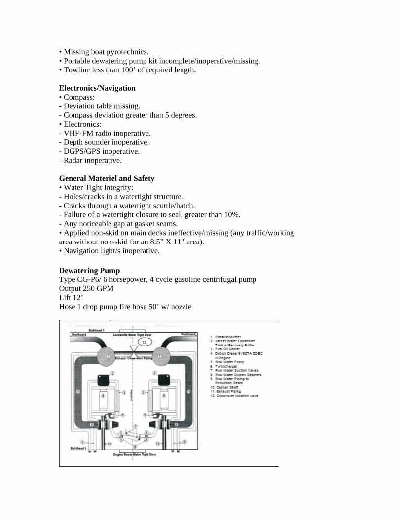
• Missing boat pyrotechnics. • Portable dewatering pump kit incomplete/inoperative/missing. • Towline less than 100’ of required length. Electronics/Navigation • Compass: - Deviation table missing. - Compass deviation greater than 5 degrees. • Electronics: - VHF-FM radio inoperative. - Depth sounder inoperative. - DGPS/GPS inoperative. - Radar inoperative. General Materiel and Safety • Water Tight Integrity: - Holes/cracks in a watertight structure. - Cracks through a watertight scuttle/hatch. - Failure of a watertight closure to seal, greater than 10%. - Any noticeable gap at gasket seams. • Applied non-skid on main decks ineffective/missing (any traffic/working area without non-skid for an 8.5” X 11” area). • Navigation light/s inoperative. Dewatering Pump Type CG-P6/ 6 horsepower, 4 cycle gasoline centrifugal pump Output 250 GPM Lift 12’ Hose 1 drop pump fire hose 50’ w/ nozzle