~4 Rockwell - VintageMachinery.orgvintagemachinery.org/pubs/1141/1244.pdf · position Install the...
8
~4 Rockwell 1 MANUFACTURING COMPANY Thm Roekw.ll Buildlng . Plttnburgh, Pa. 37-290 4" DELUXE JOINTER Delta jointers are carefully tested and inspected before shipment and if properly used will give excellent results. To receive the utmost from your machine, read the following instructions carefully. Mount the jointer on Delta stand Cat. No. 50304 or a sturdy bench. The motor can be mounted on a shelf below the jointer or behind the jointer. Assemble motor pulley Cat. No. 5650 on motor shaft. Be sure motor and arbor pulleys are in line. The Delta No. 37-290, 4" Deluxe Jointer is shipped complete with swing guard, fence, cutter head and arbor pulley. - CONSTRUCTION FEATURES The cutter head of this jointer runs in sealed ball bearings which need no lubrication throughout their life. It carries three high speed steel knives which are easily' adjusted and securely locked in their dove-tail grooves. Fig. 1. The fence is finish ground to increase accuracy, and For any other motor, order a pulley of the correct bore is heavily ribbed for rigidity and to prevent warping. 'I to fit the shaft, give the speed of the motor, and spec& , that you want the right diameter for running a 2 3/4-inch The fence can be easily locked in any position across me pulley * approxim*eIy 4200 vm* the table, and can be tilted 45' right Or left. It is also ~h~ cutter head must forward on u,p. If provided with an adjustable stop SO the fence can be motor runs in the -ng &=tion, rcvcrse it I returned at right angles to the table. according to the manufacturer's instructions, or in the ; case of a double-shaft motor, turn it end for end. I Front and rear tables are finish ground after as- sembly on the base. This additional operation assures The No- #800 V-Belt* offered for use * this jointer# the true alignment necessary for accurate work and is a has an outside circumfmece of rw inches- It feature found only in the larger more accommodate the usual installations. Consult your Delta . exp.ensive machines. dealer if you need a belt of other length to fit special I conditions. We recommend our No. 60-013 H. P., 115 volt, 60 cycle, 1725 R. P.M. bronze bearing motor with ?-4" shaft for medium duty work. For btavy duty work uac a No. 62-413, 4$ H. P. 1725 R. P. M. capacitor motor, 60 cycle, single phase, 115 volts, alternating current only. MOUNTING AND ASSEMBLING The jointer, shown in Fig. 1, L shipped complete in a ' single package marked No. 37-290. It consists of two I units, the body and the fence. The knife guard and a wrench for the lock screwrof the cutter head art included. ' The motor and other itcms of your order are supplied in , separate packages. In choosing a location for the machine, be sure to I allow clearance in front of and bad the tablea for Consult your Delta dealer for the correct motor if the jointing long pieces. electric current available is different from that indicated portable unit can lx made by mounting the jointer ' above. d motor on a 2 x 12-inch dressed plank 30 inches long. may be placed on any convenient work table for opcm- : Speed of the cutter head should be about 4000 rpm md stored on a shelf when not in use. 2-inch blocks for best results. The correct speed is obtained with the muat be inserted under the jointer bast for such mount- No. 60-013 or 62-413 motor by using the 6%-inch motor ing, to raise the machine 80 that the hetor can be placed : pulley No, 5650 in conjunction with the 2%~ -inch cutter ' directly back of the rear table and to allow removal of -head pulley J-17-S which is furnished on the jointer, chip. Uae long bolts thrwgh the base, blocks and plank. C S
Transcript of ~4 Rockwell - VintageMachinery.orgvintagemachinery.org/pubs/1141/1244.pdf · position Install the...

~4 Rockwell 1
MANUFACTURING COMPANY Thm Roekw.ll Buildlng . Plttnburgh, Pa.
37-290 4" DELUXE JOINTER
Delta jointers are carefully tested and inspected before shipment and if properly used will give excellent results. To receive the utmost from your machine, read the following instructions carefully. Mount the jointer on Delta stand Cat. No. 50304 or
a sturdy bench. The motor can be mounted on a shelf below the jointer or behind the jointer. Assemble motor pulley Cat. No. 5650 on motor shaft. Be sure motor and arbor pulleys are in line.
The Delta No. 37-290, 4" Deluxe Jointer is shipped complete with swing guard, fence, cutter head and arbor pulley.
- CONSTRUCTION FEATURES
The cutter head of this jointer runs in sealed ball bearings which need no lubrication throughout their life. It carries three high speed steel knives which are easily' adjusted and securely locked in their dove-tail grooves.
Fig. 1. The fence is finish ground to increase accuracy, and For any other motor, order a pulley of the correct bore
is heavily ribbed for rigidity and to prevent warping. 'I to fit the shaft, give the speed of the motor, and spec& , that you want the right diameter for running a 2 3/4-inch
The fence can be easily locked in any position across m e pulley * approxim*eIy 4200 vm* the table, and can be tilted 45' right Or left. It is also ~h~ cutter head must forward on u,p. If provided with an adjustable stop SO the fence can be motor runs in the -ng &=tion, rcvcrse it I returned at right angles to the table. according to the manufacturer's instructions, or in the ;
case of a double-shaft motor, turn it end for end. I
Front and rear tables are finish ground after as- sembly on the base. This additional operation assures The No- #800 V-Belt* offered for use * this jointer# the true alignment necessary for accurate work and is a has an outside circumfmece of rw inches- It feature found only in the larger more accommodate the usual installations. Consult your Delta . exp.ensive machines. dealer if you need a belt of other length to fit special I
conditions.
We recommend our No. 60-013 H. P., 115 volt, 60 cycle, 1725 R. P.M. bronze bearing motor with ?-4" shaft for medium duty work.
For btavy duty work uac a No. 62-413, 4$ H. P. 1725 R. P. M. capacitor motor, 60 cycle, single phase, 115 volts, alternating current only.
MOUNTING AND ASSEMBLING
The jointer, shown in Fig. 1 , L shipped complete in a ' single package marked No. 37-290. It consists of two I units, the body and the fence. The knife guard and a wrench for the lock screwrof the cutter head art included. ' The motor and other itcms of your order are supplied in , separate packages.
In choosing a location for the machine, be sure to I allow clearance in front of and b a d the tablea for
Consult your Delta dealer for the correct motor if the jointing long pieces. electric current available is different from that indicated portable unit can lx made by mounting the jointer ' above. d motor on a 2 x 12-inch dressed plank 30 inches long.
may be placed on any convenient work table for opcm- : Speed of the cutter head should be about 4000 rpm md stored on a shelf when not in use. 2-inch blocks
for best results. The correct speed is obtained with the muat be inserted under the jointer bast for such mount- No. 60-013 or 62-413 motor by using the 6%-inch motor ing, to raise the machine 80 that the hetor can be placed : pulley No, 5650 in conjunction with the 2 % ~ -inch cutter ' directly back of the rear table and to allow removal of
-head pulley J-17-S which is furnished on the jointer, chip. Uae long bolts thrwgh the base, blocks and plank. C S

Same operators ptefer to mount the motor an a shelf oelow the bench. In such installation, run the belt through a slot in the bench top,%r lacate the machine and motor so that the puileys extend beyond the edge. Arrange a chute for the chips, so that they do not fall onto the motor.
Having decided upon the arrangement most suitable ;or your needs, set the jointer body in its proposed position Install the motor pulley and drive belt. Locate the motor so that the pulleys are in line, with the shafts parallel and the belt tight enough ta prevent slipping. Ma.rk and drill the mountmg holes. Use ordinary carriage bolts of proper length for fastening the machine and *notor. ,
REAR TABLE TOO HIGH
Mount the fence on the jointer by slipping the cross dide bracket into the slot under the front table. Fig. 3. Install the knife guard J-13-S on the f m t table, con- necting the coil spring as shown in Fig. 1. The machine ~f the rear table is too high, the result will be - is now ready for adjustment and operation. shown in Fig, 3; the finished surface will be curved.
When the rear table is too low, the condition will be OPERATING ADJUSTMENTS as illustrated in Fig. 4 ; the wctk will be gouged at
the end of the cut. Although the: jointer is carefully adjusted at the
factory. it should be checked before it is put into opera- tion. Any inaccuracies due to patts shifting in transit can easily be corrected by following these directions:
Reor Table and Knife Adjustment For accurate work in most jointing operations, the
rear table must be exactly levtl with the knives at their highest point of revotution, This means, of course, that the knives must be parallel to the table and project equally from the cutter head.
I '
..'i . METHOD FOR CHECK~NG REAR TMLE ELEVATION
AND KNIFE ALIGNMENT el
As a-final check of the rear table adjustment, run-a piece of woad slowly over the knives for 6 to 8 inches; it should rest firmly on both tables, as shown in Fig. 5, with no open space under the finished cut.
Fh* 2.
. I To check the adjustment, place a steel straight edge
on the rear table, extending over the cutter head as shown in Fig. 2. Rotate the cutter head by hand. The b l a h should just touch the straight edge. If a knife
is high or low at either end, loosen ita lock screws 5-23 slightly, ~hift the blade until it just touches the straighp . . edge, and tighten securely.
REAR TABLE AT CORRECT HEIGHT Raise or lower the rear table as required, by turning
the hand knob BM-4-S. After it has baen sat at the correct height, it should not be changed, except for special operations and after sharpening hiven. nC 5.
-. 0 2 I
Dep?h of Cut The amount of material removed by a single cut can
be any thickness from a very thin shaving to j/4 inch. Adjust for depth of cut by raising or lowering the front table, using the hand knobBM-4-S,on the front of the base.
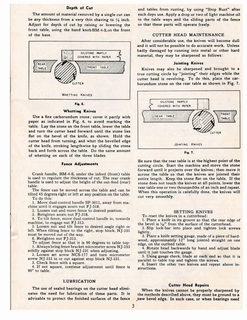
Whettimg Knives Use a fine carborundurn stone; cover it partly with
paper as indicated in Fig. 6, to avoid marking the table. Lay the stone on the front table, lower the table and turn the cutter head forward until the stone lies flat on the bevel of the knife, as shown. Hold the cutter head from turning, and whet the bevelled edge of the knife, stroking lengthwise by sliding the stone back and forth across the table. Do the same amount of whetting on each of the three blades.
Fence Adjustmsnh
Crank handle, BM-44, under the infeed (front) table is used to regulate the thickness of cut. The rear crank handle is used to adjust the height of the out-feed (rear) table. The fence can be moved across the table and can be
tilted 45 degrees right or left at any poaition on the table. To do this: 1. Move dual-control handle SP-3611, away from ma- = chine until it engages acorn nut Fj-318.
, 2. Loosen nut and move fence to desired position. 1; 3. Retighten acorn nut FJ-318. . - - 4. To tilt fence, move dual-control handle in, towards b-~' machine, to engage nut FJ-313.
5. Loown nut and tilt fence to def red angle right or left. When tilting fence to the right, stop block, NJ-231 must be moved out of the way.
6. Retighten nut FJ-313. To adjust fence so that it is 90 degrees to table top: 1. Always bring fence bracket micrometer w e w NJ-233
solidly against stop block NJ-23 1 when adjusting, 2. Loosen set acrew NCS-I77 and turn micrometer
screw NJ-233 in or out against stop block NJ-231. 3. Check fence with a square. 4. If not square, continue adjustment until fence is
90' to table.
and tables from rusting, by using "Stop Rust" after each days we. Apply a drop or two of light machine oil to the table ways and the sIiding parts of the fence I so that these pads will operate freely.
I CUTTER HEAD MAINTENANCE
After considerable use, the knives wilt become dull and it will not be possible to do accurate work. Unless badly damaged by running into metal or other hard material, they may be sharpened as follows:
Jointing Knives
Knives may also be sharpened and brought to a true cutting circle by "jointing" their edges while the cutter head is revolving. To do this. pIace the car-
I borundum stone on the rear table as show? - . In Fig. 7.
I
Be sure that the rear table is at the highest point of the cutting circle. Start the machine and-move the stone forward until it projects over the knives; then move it across the table so that the knives are jointed their entire length. Keep the stone flat on the table. If the stone does not touch the knives at all points, lower the rear table one or two thous,andths of an inch and repeat. When this operation is ca&fully done, the knives will cut very smoothly,
SETTING KNIVES To reset the knives in a cutterhead: 1. Place a knife in its groove so that the mar edge of
the bevel is H611 from the surface of the cutterhead. 2. Slip lock-bar into place and tighten lock screws
lightly. 3. Place a knife setting gauge, made of a - p i e of hard-
wood, approximately 12" tong'joint& atraight on one edge, on the outfeed table.
4. Rotate head backwar& by hand and adjust blade until it just touches the gauge.
5. Uskg gauge check, blade at ea&bd n that it is parallel to table top and tighten the ‘screws.
6. Insert the other two kniv~s and repeat abve in- atnlctions.
LUBRICATION Cutter Head RepoJrn
The use of sealed bearings on the cutter head e l i d - when the lolivn unnot =hupened by nates the need for lubrication of these parts. It is the d r ~ ~ r i b d above, arg must be ground to a advisable to protect the finished surfaces of the fence pew bevel edge. Tn mch or bsarinp need
- - 3

replacement, remove the entire cutter head with b w - ings and housings from the base -and return it to the factory. Back out the fillister head screws SP-634 from the bearing housings J-32 and J-33. inside the base, to release the cutter head assembly. When installing the cutter head in the jointer, be
sure to clean the curved seats of the base and tighten the SP-634 screws firmly into the bearing housings.
MAINTENANCE
Gum and Pitch which collects an the blades causes excessive friction as the work continues. resulting in over heating the blades, less efficient cutting. and qn- sequently loss af blade life. Use "Delta Gum and Rust Remover" to wipe this off the blades.
when these blades become dull enough so that it is noticeable when cutting, they should be resharpened. A sharp blade works easier and results in longer blade life. The penalty paid for a dull blade is less blade life and greater wear and tear on all parts of the machine. In time rust will appear on the table and fence and
other parts of the jointer, resulting in less efficienc and accuracy of the machine. Use "Stap Rust" whic b can be applied to prevent rust formation. If, howwer, rust has already formed on these parts use "DeIta Rust Remover" which will restore the machine to its original accuracy when applied. Using "Stop Rust" after each time you use the machine will put a film on the parts it b applied to, preventing rust formation.
OPERATION
The following directions will give the beginner r start on jointer operation^. Use scrap pieces of lumber to check settings and to get the feel of the operations before attempting regular work.
Jointing an Edge This is the most common operation for the jointer.
Set the guide fence square with the table. Depth of cut should be the minimum required to obtain a straight edge. Hold the best face of the piece firmly against the fence throughout the feed.
Use of Hands While Feeding
At the start of the cut, the left hand holds the work firmly against the front table and fence, while the right hand pushes the work toward the knives. After the cut in under way, the new surface rests firmly on the rear table as shown in Fig. 5. The left hand should press down on this part, at the lame time maintaining flat contact with the fence. The right hand presaea the work forward throughout,, protecting the operator against kick-back from the kn~vcs,
Fig. 8. Push BIocks. ..
lointi- Warped Pieces If the wood to be jointed is dished or warped, take
light cuts until the surface is Rat. Avoid forcing such material down against the table; excessive pressure wilI spring it while passing the knives, and it will spring back and remain curved after the cut is completed.
Joimting Short or Thin Work
When jointing short or thin pieces, use a push block to eliminate all danger to the hands. Two types are shown in Fig. 8. They are easily d e from scrap material.
Direction of Grain
Avoid feeding work into the jointer against the grain as shown in Fig. 9; the result will be hipped and sp1intercd edges. Feed with the grain as in Fig, I0 to obtain a smooth surface.
Fig. 10.
The arm of the front table and ledge of the rear table provide for cutting rabbctn up to ?4 inch deep and 4 inches wide. The operation ia illu~traM in Fig. 11. The bife guard must be removed. Set the fmet to control the width of rabbet, meamring from ihe end of the knives to the face of the fenee. Lower the front table

to determine W e &ptA of Cut. Fed slowty when rn& %is very earefdy, as the wiiI span the kriives, a deep cut, to avoid splitting the wood. For wide cuts, and they will take a "bitew from the work. with a make two or more passes at increasing depths, Use a tendency to kick back unless the piece is firmly held. put& block when rabbeting the end of narrow stock. Now push the work forward as in ordinary jointing.
The effect is to pfape off all the stock in front of the knives. to increasing depth. leaving a tapered surface.
The ridge left by the knives when starting the taper may be removed by taking a very Iight cut according to the regular method for jointing, with the front tabIe raised to its usual position.
Practice is required in this operation. and the be- ginner is advised to make trial cuts on waste material. Taper cuts over part of the length and a number of other special operations can easily be done by the tx- perieneed craftsman.
Stop Chamfering
Figure 12 shows the cutting of a stop chamfer, anm -ration for which the rear table must bt lowered from its uaual position. The tables must be set to the same level. Depth of chamfer is determind br the amount the tables an lowered. -
L: . The stop block clamped to the front end of the
fmce prevents ki&-back. Lacate it to start the chamfer at the right place, and use a similar stop black at the
Fim. 11. Cutting a Rub-. rear end d the f a c e to control length of cut. These settings should be made before the machine is startad.
Beveling Roughness caused by cutting against the grain at the To cut a bevel. lock the fence at the rqvired angle end of the chunfcr may be rmomhcd by s.nding, and ntn the work across the Imivm while keeping it
firmly against the fence and tables. Several passear the cut may be run hall way and reversed. rnay be necessary to arrive at the desired result. The tnrt stop chamfer is a bevel cut, and f made with When the angle is amall, there is little difference the f~~ ti ltd to requid angle- method
whether the fence is tilted to the right or left. How- how-, in Fig. l2 for a quare at- ever, at greater angles. approaching 45 degrems, it is increasingly difficult to hold the work properly when the fence is tilted to the right. The advantage of the double-tilting fence is appteciated under such condi- tions. When tilted to the left. the fence forms a V-shape with the tables. and the work is easiIy pressed into the pocket while passing it across the knives. If the bevel is laid out on the piece in such direction that this invoIves cutting against the grain. it will be better to tilt the fence to the right.
Toper Cuts One of the most useful jointer operations is cutting
an edge to a taper. The method can be used on a wide variety of work. Tapered legs of furniture are a com- mon example. B o l ~ T M ~ ARE LOWERLO E O w FOR
Srw GWFERING Instead of laying the piece on the front tabIe, lower
the forward end of the work onto the rear table. Do Fig. 12.
I *IMPORTANT: Base, front md rcrr t . b h mamot ba mupplicd wppratdy, u the m4uemb1ed would not bo IELP- rat& Par true alignment, we f i s h - g r i d our Wter t a b h oftar ~#tmw on th4 b a , Whtn a m y tap or bsw h i e ~ & * rhip the machine, h fmco and knife guard, to tha Iacfory for rebuildhg. The cant rill k the krt p m for the new W plun 8 fixed chargm for wcrnblin(l md @ding th tablcr **NOTE - Cutter Head Rtpeirs: Special toole are required to remove and replace ball bearings on thc cutter head. Whtn the bearinp or cutter head need replacement, order a ewnpltte new cutter head asscmbly 637-806, or return the oldbnt to us bf ing for which there is nominal charge covering repair work plus a small labor charge p# bearing for i d i n g .
Knifa ShupcaIng S c h : Our chug* for m-grkdhg and lstrinp tmivca will be a no- mt pst M F.O.B. fawry, .. Bt sure to aend the complete cutter head aswmbly with bear- and h o w h p , lcna pulley, by p r e d exprw w p d imurcd,
Cutterheads may be returned to: R O C K W E L L M A N U F A C T U R I N G C O M P A N Y D e l t a P o w e r T o o l D i v i s i o n T u p e l o , M i s s i s s i p p i A t t e n t i a n l S e r v i c e b e o a r t m e n t <, -

SAFETY RULES 1. Always keep your hands on top of the work.
2. Always hold the work firmly on the tahle or against the fence.
3. Always turn the concave side of stock toward the table and cut with the grain, not agair~st it.
4. Never run a piece of stock shorter than 12 inches across the jointer.
5. Do not operate the jointer unless the guard is in place and working.
6. Do not use the jointer when the knives are dull.
7. Never attempt to run a piece of wood across the joinker until the machine is rufining at full speed.
8. Set the fence at right angles to the table. Test with 'a square.
9. . Ifythe stock is not held down on the rear table after passing over the cutter head, the machine will not produce a true surface.
ROCKWELL GUARANTEE Rockwell i s proud of the quality of the power tools which it sells. The component par ts of our tools are inspected at various stages of produc- tion, and each finished tool i s subjected t o a final inspect ion before i t is placed i n its specially designed carton to await shipment. Because of our confidence in our engineered qual i ty , we agree to repair or replace any part or parts of Rockwell Power Tools or Rockwell Power T o o l Accessories which examination proves b be defective in workmanship or material. In order to take advantage o f this guarantee, the comple t e Della or other Rocf t~ve l l machinery part or accessory m u s t be returned prepaid to the appropriate Factory, Rockwell Service Center, ox Author- ized Service Sfation for our examination. This guaruntee, o f course, does not include repair or replacement required because of misuse, abuse, or normal wear and tear. Repairs made by other than our Factory, Rock- well Service Center, or -Authorized Service Station, relieves Rockwel l of further liability under this guarantee. This guarantee i s made expressly in place o f all other guarantees expressed or impl ied with respect to f i tness , merchantabil i ty , or qual i ty .

I2 2 1
RISER BLOCK ASSEMBLY IS NOT SUPPLIED AS STANDARD EQUIPMENT. IT IS AVAILABLE FOR USE WITH COMBINATION UNIT AND DELTASHOP