3M™ Optical Lighting Film 2405 Product Bulletin 2405...
10
3M™ Optical Lighting Film 2405 Product Bulletin 2405 Revision C, October 2017 Product Description 3M™ Optical Lighting Film (“OLF”) is a transparent plastic film with a precise prism structure on one side and a very smooth surface on the other side (Figure 1). This construction allows OLF to be highly reflective at specific angles of incidence or almost transparent at other angles. This construction allows light to be transported and distributed uniformly. Product Use When used and constructed as described in this document, OLF can be used for a variety of lighting applications. Depending upon the application and desired lighting effect, this film is suitable for use with both linear and point light sources. OLF is intended to enhance light fixtures and boxes to provide brighter, more uniform lighting distribution, as well as directional light management. Some examples of end use applications are: • Creating brighter, more uniformly distributed light in indoor and outdoor light fixtures (including architectural and functional lighting applications) • Lining light pipes to provide light dispersion across a broad area • Enhancing illuminated signs, bus shelters and transportation light boxes IMPORTANT NOTE i Any application or use of OLF must include protection from the following: - Exposure to radiant energy wave lengths below 380nm (Ultraviolet) - Any abrasive conditions, which may scratch the film Figure 1. OLF construction
Transcript of 3M™ Optical Lighting Film 2405 Product Bulletin 2405...
3M™ Optical Lighting Film 2405 Product Bulletin 2405Revision C, October 2017
Product Description3M™ Optical Lighting Film (“OLF”) is a transparent plastic film with a precise prism structure on one side and a very smooth surface on the other side (Figure 1). This construction allows OLF to be highly reflective at specific angles of incidence or almost transparent at other angles. This construction allows light to be transported and distributed uniformly.
Product UseWhen used and constructed as described in this document, OLF can be used for a variety of lighting applications. Depending upon the application and desired lighting effect, this film is suitable for use with both linear and point light sources.
OLF is intended to enhance light fixtures and boxes to provide brighter, more uniform lighting distribution, as well as directional light management. Some examples of end use applications are:
• Creating brighter, more uniformly distributed light in indoor and outdoor light fixtures (including architectural and functional lighting applications)
• Lining light pipes to provide light dispersion across a broad area• Enhancing illuminated signs, bus shelters and transportation light boxes
IMPORTANT NOTEiAny application or use of OLF must include protection from the following:
- Exposure to radiant energy wave lengths below 380nm (Ultraviolet)- Any abrasive conditions, which may scratch the film
Figure 1. OLF construction

3M™ Optical Lighting Film 2405
Product CharacteristicsThe manufacturing process for this film creates a thin line, called a tooling line, across the film that repeats approximately every 42.2 in. (107.2 cm), as shown in Figure 2.
Product Performance
Recommended 3M Products
Extractor
• 3M Light Enhancement Film type 3635-100 (diffuse reflection 94.5%)
Fastening
• Scotch transfer adhesive film (transparent) Types 467/468
Theory of Total Reflection
Reflection and Transmission at InterfacesTotal reflection can be observed on optically clear materials with different refraction indexes (n). During transition from an optically denser medium (i.e. glass or water) to an optically thinner medium (i.e. air), the light ray is split into reflective and transmitting proportions (Figure 3). The proportion of reflecting light increases with greater angle of incidence until total reflection is achieved. The critical angle, at which the total reflection occurs depends on the densities of the media involved.
Characteristic Value Applicable Standard
Thickness20 mils ± 3 mils(0.508 mm ± 0.076 mm)
ASTM D-374, D
Weight 1.1 lb ± 0.04 lb/yd.2(0.50 kg ± 0.02 kg/m2)
ASTM D-648, 264 PSI
Prism angles 90° ± 20 minute bend N/A
Prism flatness < 1 wavelength light N/A
Width 37 in. (953 mm)39 in. (991 mm) N/A
Characteristic Value Applicable Standard
Distortion temperature 265 °F (129.4 °C) N/A
Fire resistance Approved U.L. 94H, B2 (DIN 4102-1)
Elongation at break lengthwise 8,000 psi (562 kg/cm2), 60% elonga-tion ASTM D-882
Elongation at break transverse 8,000 psi (562 kg/cm2), 8% extension ASTM D-882
Young’s Modulus (E module) 240 Kpsi (16,900 kg/cm2) ASTM D-882
Light obscuration < 1% N/A
Absorption capacity < 50 dB/m N/A
Figure 2. Tooling lines
Tooling Lines
42.2 in. (107.2 cm)37.5 in. (953 mm)
Figure 3. Total reflection
Airn2 = 1.0
Polymern1 = 1.5
Total Reflection
2 Product Bulletin 2405 - Revision C, October 2017

3M™ Optical Lighting Film 2405
Theory of Total Reflection (continued)
Reflection Behavior of OLFOLF utilizes the phenomenon of total reflection. On the prismatic surface, incident light entering the film is deflected twice by means of total reflection and is refracted back towards the input direction (Figure 4a), creating a mirror-like reflection. However, unlike a mirror, OLF may also be transparent for greater angles of incidence. The passing light is then altered in its direction, as with a lens, and passes through the OLF with an exit angle different from the entry angle (Figure 4b).
Beam Path in OLFIn the three-dimensional representation (Figure 5), the beam path is followed in the material under total reflection conditions.
The light ray enters into the material (1), is refracted towards the optically denser material and is reflected by the first prism face (2).
From there, the beam is directed to the second prism face and is reflected (3), finally emerging from the material (4). As OLF is very thin (0.5 mm), points 1 and 4 are located very closely together. One can therefore also imagine OLF simplified as a mirrored surface in the angular range of total reflection.
Requirement to the Light SourceUsing a ray-tracing procedure, the beam path for different angles was calculated and the usable angle range was determined. All the beams that leave the light source within a cone with an opening angle <27.6° are reflected by OLF (Figure 6). Beams that hit OLF at angles >27.6°, exit through the film.
Figure 4. Reflection and transmission on OLF
Figure 5. Beam’s path in OLF
Figure 6. Requirement to Light Source
Product Bulletin 2405 - Revision C, October 2017 3

3M™ Optical Lighting Film 2405
ApplicationsBesides the refractive characteristics suggesting OLF as an optical component, there are three basic applications on which a multitude of applications can be based:
• Light guide• Lighting fixture• Flat light box
Light GuideOLF can be used as a light guide to transport light over distance. A light guide application consists of a single, or point light source converted to a linear light source by a reflector collimating the light rays in a specific direction and angle (<27.6°), and a tube lined with OLF (Figure 7). The properties of the OLF and the effects of Total Reflection cause the light to remain in the tube and be transported down the tube with minimal light loss. The action of transporting the light down the tube is said to “couple” the light within the tube.
In this application, the flexible film is rolled into a tube with its prisms pointing outwards and running lengthwise along the tube. The flexibility of the film allows for the free design of the light guide's cross-section (Figure 7, “Light guide cross-section examples,” on page 4). The distance the light is transported down the light guide depends on the diameter of the light guide. The greater the diameter of the light guide, the fewer reflections there will be resulting in more light available at the end of the light guide (Figure 9, “Decrease of the light quantity with light guides in dependency of the degree of reflection R,” on page 5).
Figure 7. Light guide cross-section examples
Figure 8. Aspect ratio
4 Product Bulletin 2405 - Revision C, October 2017
3M™ Optical Lighting Film 2405
Light Guide (continued)
The effectiveness of the light transport can be determined by the light guide aspect ratio (AR). Aspect ratio, or length-to-diameter ratio, is defined as the diameter of the light guide compared to the length of the light guide. To calculate the aspect ratio divide the length of the light guide by the diameter of the light guide.
Aspect Ratio = Length of Light Guide Aspect Ratio of 60 = 6 meter (600 cm) light guide Diameter of Light Guide 10 cm diameter tube
The aspect ratio of a light guide allows comparison of different light guide systems or designs. Light guides with the same AR transport the same quantity of light. Light guides with small ARs transport light over short distances; light guides with larger ARs transport light over longer distances.
With an AR of 60 and a diameter of 10 cm, a transport length of 6 m is possible. With an AR of 60 and a diameter of 50 cm, a transport length of 30 m is possible.
AR of 60 * 10 cm = 600 cm = 6 m;AR of 60 * 50 cm = 3000 cm = 30 m
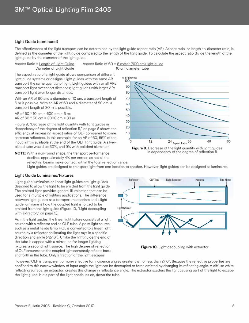
Figure 9, “Decrease of the light quantity with light guides in dependency of the degree of reflection R,” on page 5 shows the efficiency at increasing aspect ratios of OLF compared to some common reflectors. In this example, for an AR of 60, 55% of the input light is available at the end of the OLF light guide. A silver-plated tube would be 30%, and 9% with polished aluminum.
NOTE: With a non-round shape, the transport performance declines approximately 4% per corner, as not all the reflecting beams make contact within the total reflection range.Light guides are designed to transport light from one location to another. However, light guides can be designed as luminaires.
Light Guide Luminaires/FixturesLight guide luminaires or linear light guides are light guides designed to allow the light to be emitted from the light guide. The emitted light provides general illumination that can be used for a multiple of lighting applications. The difference between light guides as a transport mechanism and a light guide luminaire is how the coupled light is forced to be emitted from the light guide (Figure 10, “Light decoupling with extractor,” on page 5).
As in the light guides, the linear light fixture consists of a light source with a reflector and an OLF tube. A point light source, such as a metal halide lamp HQI, is converted to a linear light source by a reflector collimating the light rays in a specific direction and angle (<27.6°). Unlike the light guide the end of the tube is capped with a mirror, or, for longer lighting fixtures, a second light source. The high degree of reflection of OLF ensures that the coupled light constantly reflects back and forth in the tube. Only a fraction of the light escapes.
However, OLF is transparent or non-reflective for incidence angles greater than or less than 27.6°. Because the reflective properties are confined to this narrow window of input angle the light can be decoupled or force emitted by changing its reflecting angle. A diffuse white reflecting surface, an extractor, creates this change in reflectance angle. The extractor scatters the light causing part of the light to escape the light guide, but a part of the light continues on, down the tube.
Figure 9. Decrease of the light quantity with light guides in dependency of the degree of reflection R
% Brightness
Aspect Ra o
Figure 10. Light decoupling with extractor
Reflector OLF Tube Light Extractor Housing End Mirror
Light Source
Product Bulletin 2405 - Revision C, October 2017 5
3M™ Optical Lighting Film 2405
Light Guide Luminaires/Fixtures (continued)
Uniformity of light output is often considered a design requirement for linear light luminaires. Uniformity is achieved by effectively designing the extractor to interact with small amounts of light closer to the light source where the light is brightest and interact more strongly with light farther from the light source where the light is weakest.
To create an extractor that emits light uniformly along the length of the luminaire the extractor increases in its width as the light quantity is decreased (Figure 10, “Light decoupling with extractor,” on page 5). In areas of high light output less extraction is required; in areas of low light output more extraction is required.
It is recommended from practical experience that the maximum usable aspect ratio is 40 to 1. Greater aspect ratios suffer from non-uniformity.
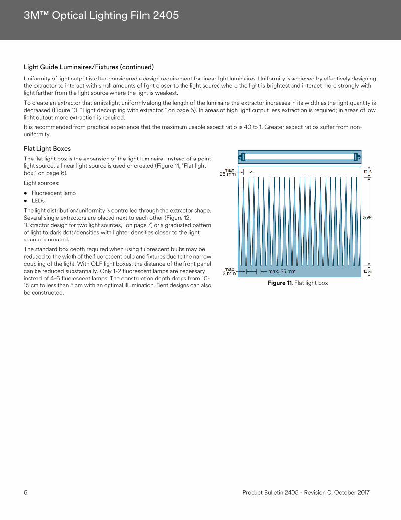
Flat Light BoxesThe flat light box is the expansion of the light luminaire. Instead of a point light source, a linear light source is used or created (Figure 11, “Flat light box,” on page 6).
Light sources:
• Fluorescent lamp• LEDs
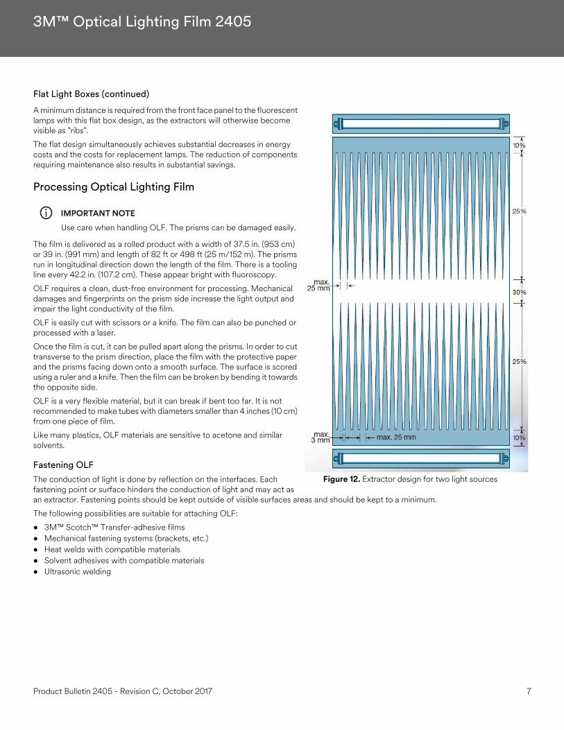
The light distribution/uniformity is controlled through the extractor shape. Several single extractors are placed next to each other (Figure 12, “Extractor design for two light sources,” on page 7) or a graduated pattern of light to dark dots/densities with lighter densities closer to the light source is created.
The standard box depth required when using fluorescent bulbs may be reduced to the width of the fluorescent bulb and fixtures due to the narrow coupling of the light. With OLF light boxes, the distance of the front panel can be reduced substantially. Only 1-2 fluorescent lamps are necessary instead of 4-6 fluorescent lamps. The construction depth drops from 10-15 cm to less than 5 cm with an optimal illumination. Bent designs can also be constructed.
Figure 11. Flat light box
6 Product Bulletin 2405 - Revision C, October 2017
3M™ Optical Lighting Film 2405
Flat Light Boxes (continued)
A minimum distance is required from the front face panel to the fluorescent lamps with this flat box design, as the extractors will otherwise become visible as "ribs".
The flat design simultaneously achieves substantial decreases in energy costs and the costs for replacement lamps. The reduction of components requiring maintenance also results in substantial savings.
Processing Optical Lighting Film
IMPORTANT NOTEiUse care when handling OLF. The prisms can be damaged easily.
The film is delivered as a rolled product with a width of 37.5 in. (953 cm) or 39 in. (991 mm) and length of 82 ft or 498 ft (25 m/152 m). The prisms run in longitudinal direction down the length of the film. There is a tooling line every 42.2 in. (107.2 cm). These appear bright with fluoroscopy.
OLF requires a clean, dust-free environment for processing. Mechanical damages and fingerprints on the prism side increase the light output and impair the light conductivity of the film.
OLF is easily cut with scissors or a knife. The film can also be punched or processed with a laser.
Once the film is cut, it can be pulled apart along the prisms. In order to cut transverse to the prism direction, place the film with the protective paper and the prisms facing down onto a smooth surface. The surface is scored using a ruler and a knife. Then the film can be broken by bending it towards the opposite side.
OLF is a very flexible material, but it can break if bent too far. It is not recommended to make tubes with diameters smaller than 4 inches (10 cm) from one piece of film.
Like many plastics, OLF materials are sensitive to acetone and similar solvents.
Fastening OLFThe conduction of light is done by reflection on the interfaces. Each fastening point or surface hinders the conduction of light and may act as an extractor. Fastening points should be kept outside of visible surfaces areas and should be kept to a minimum.
The following possibilities are suitable for attaching OLF:
• 3M™ Scotch™ Transfer-adhesive films• Mechanical fastening systems (brackets, etc.)• Heat welds with compatible materials• Solvent adhesives with compatible materials• Ultrasonic welding
Figure 12. Extractor design for two light sources
Product Bulletin 2405 - Revision C, October 2017 7
3M™ Optical Lighting Film 2405
Design Information
Light Source and ReflectorThe light source and reflector are the most important parts of an OLF system. An optimal light transport or output can only be achieved if the OLF system, light source, and reflector are well matched.
For the conduction of light, the light output must be bundled as tightly as possible. The cone of light should enter the light tube at an angle > 27.6°. Angles above 27.6° will allow the light to transmit through the tube resulting in a bright spot and a non- uniform light output near the light source.
FilterOLF light distribution systems offer the decisive advantage of light filtering. A large light-emitting surface can be changed in its coloring with comparably small filters. The use of filter wheels enables a dynamic play of colors through the OLF.
When installing the filters, sufficient ventilation of the lamp housing must be ensured. For lamps with a high UV output (e.g. mercury vapor lamps), a UV filter (glass) should always be placed in front of the OLF material to reduce the damage caused by UV light. Infrared-absorbing filters require a heat-dissipating holder that does not hinder the thermal expansion of the filter.
Light Source Housing
Depending on the light source it may be necessary to ensure adequate ventilation for the light source. A fully sealed OLF system will best protect against environmental influences.
Do not allow water to penetrate the system and contact the OLF film. Water will impair the total reflection.
To minimize the loss of light, fastening points for OLF should be provided underneath the housing enclosures outside of the visible light-emitting surface.
ExtractorHighly reflective, white, diffuse film should be used as the extractor. ScotchCal™ Light Enhancement Film 3635-100 with a 94% reflectance is recommended.
Handling Care must be used when handling this precision optical product to prevent scratching or marking the film. Marks or damage to the prisms caused by handling appear as bright spots or bright lines on a luminaire.
• Wear soft cotton or nylon gloves when handling the film to prevent fingerprints.• Handle the film in a clean and dust-free environment.• Minimize sliding the film against any surfaces to avoid prism damage.• When working with the film, keep the slip sheet underneath the film to protect against surface damage.
8 Product Bulletin 2405 - Revision C, October 2017

3M™ Optical Lighting Film 2405
CuttingSince this film is made from a thin plastic material, cutting it to the desired size is easy.
To Cut Along the Prisms
1. Lay the film on a smooth, clean surface with the prisms facing up.2. Create a notch to start the cut.3. Tear the film along the prism.
To Cut Perpendicular to the Prisms across the film width
1. Lay the film on a smooth, clean surface with the prisms facing up.2. Using a straight edge, score the prism surface of the film with a razor or scoring knife.3. Break the film evenly along the line by bending the film away from the scored side.
MaintenanceWhen required, clean the film by dusting with a soft dry cloth. If necessary, a cloth dampened with water may be used to clean the smooth side but dry before any water marks appear. Watermarks will act as an extractor and create hot spots on the luminaire. Do not use harsh cleaning products or solvents; these will damage the film's optical properties.
Transportation and StorageUntil you are ready to install, store the film:
• In its original packaging (a maximum of four rolls may be stacked per pallet)• In a clean, dry area, out of direct sunlight• At 40° F to 100° F (4° to 38°C)
Health and Safety
CAUTION!When handling any chemical products, read the manufacturers' container labels and the Safety Data Sheets (SDS) for important health, safety and environmental information. To obtain SDS sheets for 3M products go to 3M.com/SDS, or by mail or in case of an emergency, call 1-800-364-3577 or 1-651-737-6501.
When using any equipment, always follow the manufacturers' instructions for safe operation.
Technical InformationTechnical information and data, recommendations, and other statements provided by 3M are based on information, tests, or experience which 3M believes to be reliable, but the accuracy or completeness of such information is not guaranteed. Such technical information and data are intended for persons with knowledge and technical skills sufficient to assess and apply their own informed judgment to the information. The typical values shown should not be used for the purpose of specification limits. If you have questions about OLF, contact the Technical Service helpline at 1800328-3908.
Product Bulletin 2405 - Revision C, October 2017 9
3M™ Optical Lighting Film 2405
WARRANTY
Product
3M Optical Lighting Film 2405 (OLF).
3M Basic Product Warranty
OLF is warranted to be free of defects in materials and manufacture (“3M Basic Product Warranty”) at the time of shipment (“Warranty Period”) by 3M or its authorized distributor.
Limited Warranty
1. For OLF, 3M makes the 3M Basic Product Warranty only.2. For a buyer’s convenience, 3M may provide engineering or technical information, recommendations, installation instructions or guides,
and other information or materials relating to OLF (“Other Product Information”), but 3M makes only the 3M Basic Product Warranty and does not warrant any Other Product Information.
3. 3M has no obligation under the 3M Basic Product Warranty as to OLF that has been: (a) modified, altered or processed in any manner; (b) stored, applied, installed, or used in a manner other than that 3M recommends in this document and in all Other Product Information; (c) damaged through contact with a person or thing, misuse, accident, neglect, or other action by anyone other than 3M; (d) improperly installed, including, without limitation, installation after the expiration of OLF’s shelf life or installation without proper surface prepara-tion, or (e) exposed to excessive heat, humidity, dirt or UV light.
4. EXCEPT TO THE EXTENT PROHIBITED BY APPLICABLE LAW, THE 3M BASIC PRODUCT WARRANTY IS MADE IN LIEU OF ALL OTHER WARRANTIES, RIGHTS OR CONDITIONS, EXPRESS OR IMPLIED, INCLUDING, BUT NOT LIMITED TO, ANY IMPLIED WAR-RANTY OF MERCHANTABILITY, SATISFACTORY QUALITY, FITNESS FOR A PARTICULAR PURPOSE AND THOSE ARISING FROM A COURSE OF DEALING, CUSTOM OR USAGE OF TRADE. THE BUYER IS RESPONSIBLE FOR DETERMINING IF OLF IS SUITABLE FOR ITS PARTICULAR PURPOSE AND APPLICATION METHODS.
5. 3M must receive any 3M Basic Product Warranty claim in writing no later than 10 business days after (a) the end of the Warranty Period or (b) the discovery of the 3M Warranty claim, whichever is earlier.
Limited Remedy
IF ANY PRODUCT IS PROVEN NOT TO HAVE MET THE 3M BASIC PRODUCT WARRANTY DURING THE WARRANTY PERIOD, THEN THE BUYER’S EXCLUSIVE REMEDY, AND 3M’S SOLE OBLIGATION, WILL BE, AT 3M’S OPTION, TO REPLACE THE NONCONFORMING PRODUCT OR TO REFUND THE NONCONFORMING PRODUCT’S PURCHASE PRICE.
Limitation of Liability3M WILL NOT UNDER ANY CIRCUMSTANCES BE LIABLE TO A BUYER FOR DIRECT (other than the Limited Remedy stated above), SPECIAL, INCIDENTAL, INDIRECT OR CONSEQUENTIAL DAMAGES (INCLUDING, WITHOUT LIMITATION, LOSS OF PROFITS) IN ANY WAY RELATED TO THE PRODUCT, THIS DOCUMENT OR OTHER PRODUCT INFORMATION, REGARDLESS OF THE LEGAL OR EQUITABLE THEORY ON WHICH SUCH DAMAGES ARE SOUGHT.
© 3M 2017. All rights reserved. 3M is a trademark of 3M. Used under license in Canada. All other trademarks are property of their respective owners.Revision C, October 2017 Please recycle.
Commercial Solutions3M Center, Building 220-12E-04St. Paul, MN 55144