37717 COF (Rev A) manual before installing or servicing lift. Failure to do so may result in serious...
38
2 Century 2 W ARNING Read manual before installing or servicing lift. Failure to do so may result in serious bodily injury and/or property damage. ual Man "Providing Access to the World" International Corporate Hdqrs: P.O. Box 310 Winamac, IN 46996 USA 1-800-THE LIFT ® (574) 946-6153 FAX: (574) 946-4670 ® ® NCL954 Century 2 Series NCL954 Century 2 Series DOT — Public Use Lift DOT — Public Use Lift “DOT — Public Use Lift” verifies that this platform lift meets the “public use lift” requirements of FMVSS No. 403. This lift may be installed on all vehicles appropriate for the size and weight of the lift, but must be installed on buses, school buses, and multi- purpose passenger vehicles other than motor homes with a gross vehicle weight rating (GVWR) that exceeds 4,536 kg (10,000 lb). NCL954 Series NCL954 Series Public Use Wheelchair Lifts FA Service Manual for: 37717 Rev. A April 2012 Series FA 33220
Transcript of 37717 COF (Rev A) manual before installing or servicing lift. Failure to do so may result in serious...

2Century 2
WARNING
Read manual before installing or servicing lift. Failure to do so may result in serious bodily injury and/orproperty damage.
ualMan
"Providing Access to the World"International Corporate Hdqrs: P.O. Box 310 Winamac, IN 46996 USA
1-800-THE LIFT® (574) 946-6153 FAX: (574) 946-4670
®® N
CL9
54
Cen
tury
2 Se
ries
NCL9
54
Cen
tury
2 Se
ries
DOT — Public Use LiftDOT — Public Use Lift“DOT — Public Use Lift” verifies that this platform lift meets the “public use lift” requirements of FMVSS No. 403. This lift may be installed on all vehicles appropriate for the size and weight of the lift, but must be installed on buses, school buses, and multi-purpose passenger vehicles other than motor homes with a gross vehicle weight rating (GVWR) that exceeds 4,536 kg (10,000 lb).
NCL954
Series
NCL954
SeriesPublic Use Wheelchair Lifts
FA
Service Manual for:
37717 Rev. A
April 2012
Series FA
33220

Two Braun Serial No./Series No. identification tags (shown below) are posted on the lift. One I.D. tag is posted on the opposite pump side vertical arm. A second I.D. tag is located on the opposite pump side tower. Both I.D. tags provide the product identification infor-mation provided on the warranty/registration card. Record the information in the space provided (or document on a copy). This information must be provided when filing a war-ranty claim or ordering parts.
Warranty and Registration Instructions
Immediately upon receiving the lift, examine the unit for any damage. Notify the carrier at once with any claims.
Two warranty/registration cards (shown right) are located in the lift-mounted manual storage pouch. The sales representative must process one of the cards. The consumer must fill out the other card and mail it to The Braun Corporation. The warran-ty is provided in this manual. The warranty cards must be processed to activate the warranty.
Congratulations
We at The Braun Corporation wish to express our fullest appreciationon your new purchase. With you in mind, our skilled craftsmen have designed and assembled the finest lift available. This manual provides service-related material. Refer to the FMVSS No. 403 Quick Reference Installation Sheet for installation instructions, operating instructions and maintenance procedures. Braun Century Series™ lifts are built for dependability and will provide years of pleasure and independence as long as the lift is installed and serviced as specified by a Braun certified technician, and the lift is operated by an instructed person.
Sincerely, THE BRAUN CORPORATION
Ralph W. Braun Chief Executive Officer
OWNER'S WARRANTY REGISTRATION
PURCHASED FROM
XXXXXXXXXX XX-XXXXX
DATE INSTALLED
NAME
ADDRESS
CITY
TELEPHONE
TO VALIDATE WARRANTYREGISTRATION CARDS MUST BE RETURNED TO THE BRAUN CORPORATION.
OWNER
STATE ZIP
Sample Warranty/Registration Card
Serial No.Model No.
The Braun Corporation
XXXXXXXXXX
XX-XXXXX
XX/XX/XXXX
1-800-THE-LIFTBRAUNLIFT.COM
TM
MFG DATE
SERIAL NUMBER
TM
DOT Public Use Lift MODEL#
Max. Lifting Capacity - 600Lbs.
Model No.
Serial No.
Dat

Page 1
Troubleshooting and Maintenance
Lift Terminology................................................................ 2Switch and Sensor Locations ......................................... 3
................. 4 ................................. 5
.......................................... 6-7 ...................................................... 7
........................................ 8 ...................................................... 10
Lift Electrical Schematic ............................................... 15 ....................................................... 16
Hydraulics
..................................................... 17 ..................................................... 18
...................................................... 19 Repair Parts
Pump Module .......................................... 20
........................................... 21 Lift Exploded Views and Parts Lists
.......................... 22 ....................... 23
....................................... 24 ................................. 25
......................... 26.............................................. 27
................................................ 28 ................................................... 29
........ 30 Warranty
® Limited Warranty .......................................... 31-33
Contents
Page 2
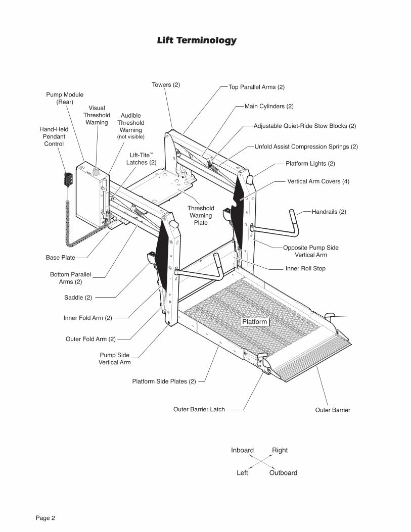
Lift Terminology
UPDOWN32819
FOLDUNFOLD
32820®
(Rear)
Hand-Held Pendant Control
Base Plate
Main Cylinders (2)
Handrails (2)
Bottom Parallel
Platform Lights (2)
Right
Lift-Tite™ Latches (2)
Platform Side Plates (2)
Platform
Left
Towers (2)
Threshold Warning
Plate
Threshold Warning
ThresholdWarning
Inner Roll Stop
Lift Terminology
Saddle (2)
Page 3
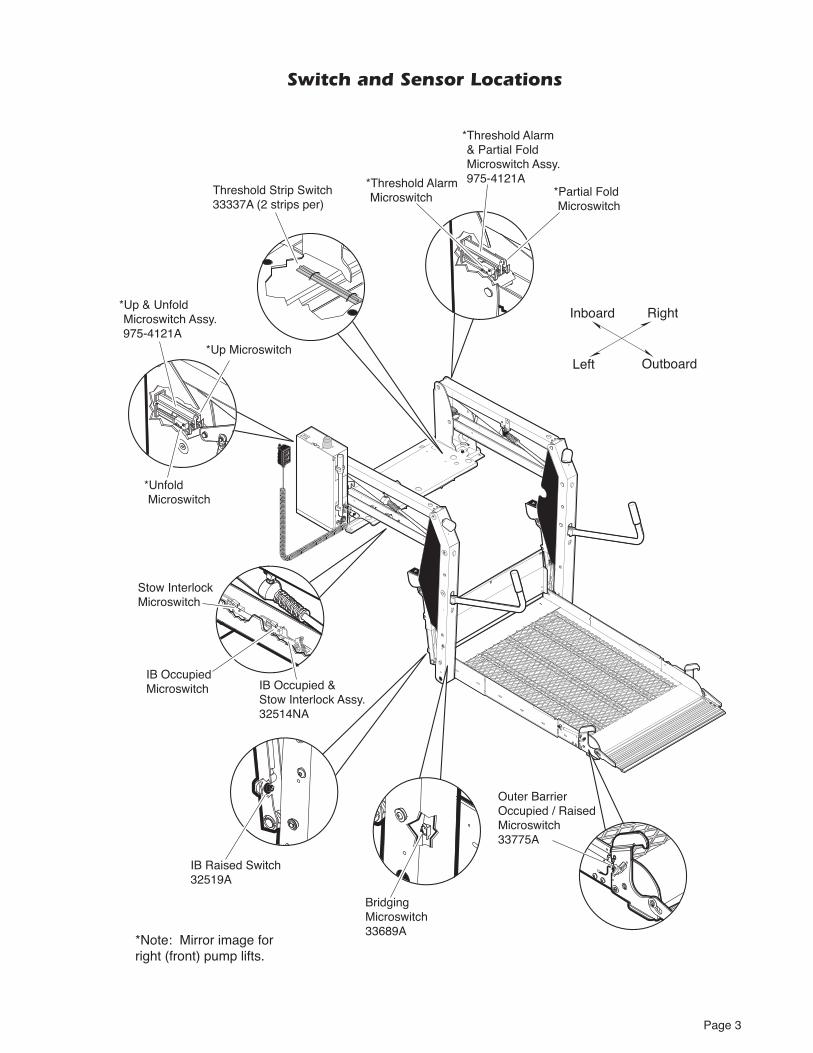
Switch and Sensor Locations
UPDOWN32819
FOLDUNFOLD
32820 ®
Inboard
Outboard
Right
Left
Threshold Strip Switch33337A (2 strips per)
*Up Microswitch
IB OccupiedMicroswitch
Stow Interlock Microswitch
IB Occupied & Stow Interlock Assy.32514NA
*Unfold Microswitch
*Threshold Alarm Microswitch
*Up & Unfold Microswitch Assy. 975-4121A
*Threshold Alarm & Partial Fold Microswitch Assy. 975-4121A
IB Raised Switch32519A
*Partial Fold Microswitch
Outer BarrierOccupied / RaisedMicroswitch33775A
*Note: Mirror image forright (front) pump lifts.
Bridging Microswitch33689A
Page 4
-
3. Reinstall threshold warning plate.
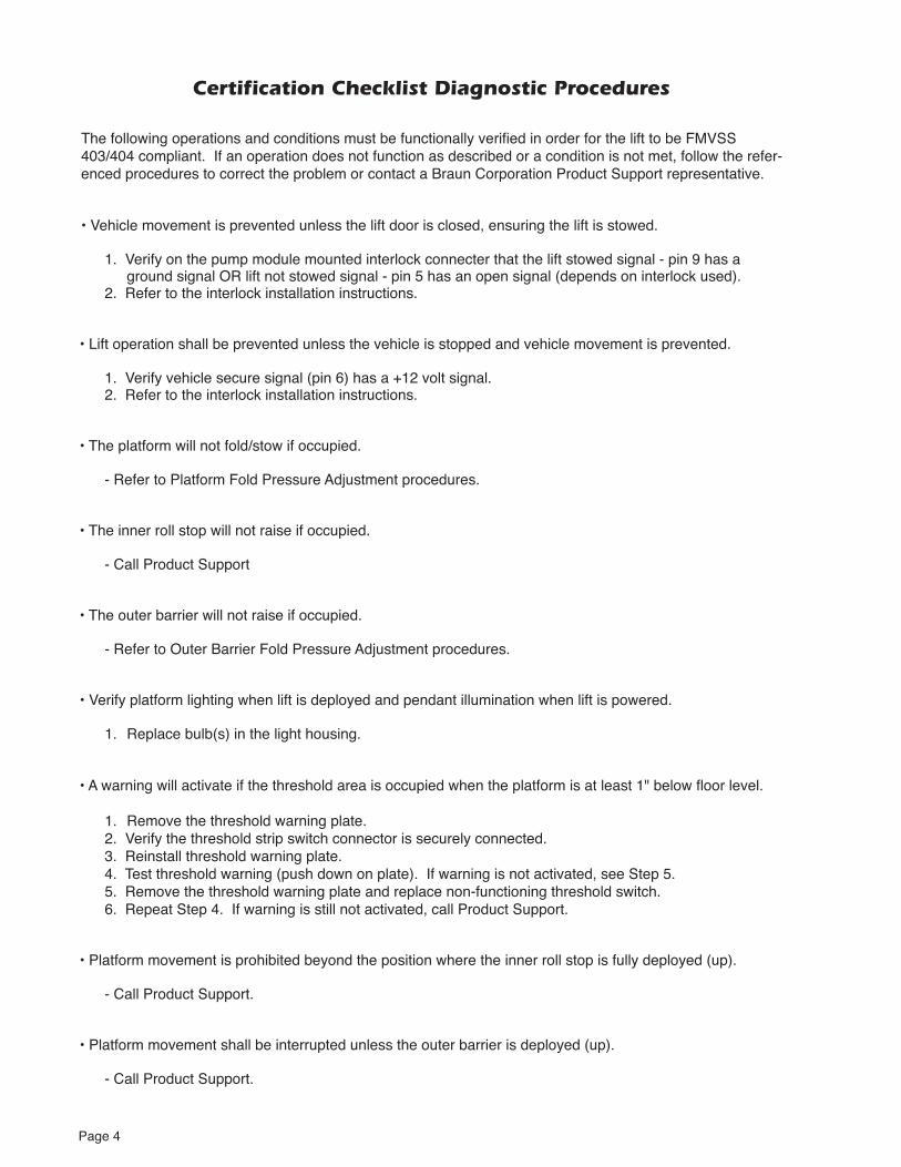
Certification Checklist Diagnostic Procedures

Page 5
Do not adjust this valve.(located beside solenoid valves)
pressed.-
platform.
Platform Fold Pressure Adjustment
Platform Fold
screw and tighten hex

Page 6
Platform Angle Adjustment
Adjustment Procedure:
of the platform (see photo at right and details on following page).
-
of the platform.
®
When -
-
arms (see photo at right and details on following page).
Floor Level Adjustment: Fol--
positioning as detailed in Tower
Stop Vertical
The angle of the platform at
the angle of the platform when
platform.
-
Figure A
Heel
Platform heel
Barrier
Floor
Wedges (option)
Figure B
2 1

Page 7
AB
Platform Angle Adjustment
Platform Stop Blocks
Gap not permitted.
C D
Stop Block Guideline
All Lift Models
Right Wrong
to raise
end of platform
Stop Vertical Stop Vertical
to lower
end of platform
®

Page 8
Tower 3 (Alarm) Switch Adjustment
-dant control.
-
-
Tower 4 (Fold) Switch AdjustmentPartial Fold Switch
control. 2. View the Tower 4 microswitch inside
-
lift is a mirrored image.as needed only.
Tower 1 (Unfold) Switch AdjustmentFloor Position from Stow
-
-
-
-
of the saddle and the lower parallel
Tower 2 (Up) Switch AdjustmentFloor Position from Below Floor
control. -
pressing the pendant UP switch. -
-
A
B
-
Tower Microswitch Adjustment
TOWER
2TOWER
132942
TOWER
4TOWER
332943 Figure B
TOWER
2TOWER
132942
TOWER
4TOWER
332943

Page 9
NOTES

Page 10
UPDOWN32819
FOLDUNFOLD
32820®
Maintenance and Lubrication
Lubrication Diagram
Bearings (4)LO
LO
Lift-Tite™ Latches
LO
Lift-Tite™
(2 springs - 4 Points) LO
LO
Inner Roll Stop
LO
LO
LO
(2 Springs - 4 Places) LO
Bearings (4)LO
Bearings (8)LO
Saddle Bearing (2)
DE
Bearings (8)LO
Lift-Tite™ Latch Rollers (2) LO
Latch Roller Bearing (2)
LO
Cam Followers (4)LO
Roller Pin Bearings (4)
LO
LO
Inner Roll Stop
and Slots (2) LO
LOBearings (4)
LO
LG
Lubricant Type Lubricant Amount Part No.
LO - Light Oil
LG - Light Grease
DE - Door-Ease
15807
15806
15805
Light Penetrating OilPenetrating Oil
16 oz.
1.68 oz.
Light Grease 14 oz.Can
LG

Page 11
Maintenance and Lubrication Schedule
Maintenance and lubrication procedures must be performed as
authorized service technician. Failure to do so may result in serious bodily injury and/or property damage.
-
-
life of the lift.
-
-
to the components. Platform components exposed to
extra attention.
-
-
4500 cycle maintenance
-
Cycle Counter: NCL-2 Series lift models are
Lift-Tite™
Lift-Tite™
points (2 springs - 4 points)
Inspect Lift-Tite™ latches and gas (dampening) -
snap rings) and proper operation
Lift-Tite™
Correct or replace damaged parts.
750 Cycles
WARNING

Page 12
750 Cycles
1500 Cycles
Maintenance and Lubrication Schedule
Replace damaged parts.
correct as needed.
Inner fold arm cam followers (4)
Inspect Lift-Tite™
Inspect inner roll stop for:
and for proper operation
springs (2) for wear or damage and for proper operation
Perform all procedures listed in previous section also
-
Correct as needed.
Correct as needed.
spring(s)
condition
Inspect lift for rattles

Page 13
Perform all procedures listed in previous section also
4500 Cycles
-
-
Inspect gas springs (cylinders - 6) for wear or dam-
Maintenance and Lubrication Schedule
1500 Cycles
Inspect external snap rings:
™ latch rollers (2)™ latch gas (dampening) springs (4)
®
-
Replace if needed.
Tighten or replace if needed.
-
Replace if needed.
-

Page 14
4500 Cycles
-Consecutive 750 Cycle Intervals
-
Maintenance and Lubrication Schedule

Page 15
Lift Electrical Schematic
UP/FOLDSOLENOID
PUMP
1
2
CIRCUITSENTRY
(CIRCUIT BREAKER)
INTERLOCK
HYDRAULIC
(UP)
M
POWERSTUD CHASSIS
GROUND
CHASSISGROUND
TO ALLCIRCUIT
BREAKER(CB1)
GROUNDS
TO ALLCOMMON (C1)
GROUNDS
DOWN SOLENOID
(N.C. Valve)
M
BATTERY
CHASSIS GROUND
CIRCUIT BREAKER/FUSE
JUNCTION
MOTOR
SWITCH
CONNECTER
FLASHER
SOLENOID
NOTES:
1) JUNCTIONS ONLY OCCUR ATMARKED INTERSECTIONS.
UP MICROSWITCH
UNFOLDMICROSWITCH
COUNTER
FOLD RELIEFSOLENOID
( N.O. Valve)
FOLDRELAY
NO
NC
C
NO
NC
C
POS.+
E
NEG. -
4
3
THRESHOLD/ALARMMICROSWITCH
PARTIAL FOLDMICROSWITCH
NO
NC
C
NO
NC
C
00000
6 77
5 43
6 5 43
22
11
21
43
56789
21
43
56789
THRESHOLDSTRIP SWITCHES
LIFT POWER SWITCH
MICROSWITCH
CAPACITOR
DIODE
SYMBOLDESCRIPTION
COUNTER
RELAY
LIGHT
BEEPER
NO
NC
C
+
E
-
00000
UP
DOWN
UNFOLD
FOLD
LG
LIFTSWITCH BOX
FUSE
FUSE
+ -
REDUNDANTPOWERRELAY
8586
87
87A
30
NO
NC
C
IB RAISEDSWITCH
STOW INTERLOCKMICROSWITCH
NO
NCC
OUTER BARRIEROCCUPIED / RAISED
MICROSWITCH
BRIDGINGMICROSWITCH
NO
NCC
8586
87
87A
30
IB OCCUPIED MICROSWITCH
NO
NC
C
85
8685
87
87
87A
30
LIGHTRELAY
85 86
87
87A
30
VEHICLE SECURE SIGNAL
LIFT STOWED SIGNAL
LIFT NOT STOWED SIGNAL
(GROUND)YL/LT. BU(18)
YL/LT. BU(18)GY/RD(18)
BK(16)WH(18)
WH(18)
WH(18)
WH
(18)
GN
(18)
BU(18)
BU(18) DK. BU(18) DK. BU(18)TN/OR(18)
RD(18)BK(18)
RD/WH(18)
RD/WH(18)
RD/WH(18)
GOLD(22) GOLD(22)SILVER(22)SILVER(22)
RD
/WH
(18)
GN
(20)
GN
(20)
GN(18)
BN(20)
OR(18)GN(18)
RD(18)WH(18)
BK(18)
GN(18)
WH
(18)
GN
(18)
GN(18) DK. BU(20)
BK(16) RD(18)
RD(18) BK(18)
RD(18)
BK(20)GN(20)WH(20)
RD(18)WH(18)BK(18)
BK(18)
WH(18)
WH(18)
DK. BU(18)
WH(18)
LT. BU/GN(18)
GN(18)
GN(20)
WH(18)
WH
(18)
BK(18)
RD(18)
OR
(12)
OR
(12)
OR
(12)
OR(12)
OR
(12)
RD(18)
RD
(18)
BK
(18)
GN
(18)
GN(18)GN(18)
RD(18)BK(20)
BK(18)
BK(18)
BK(20)
GN(14)
GN(20)
GN
(20)
BK(22)RD(22)
BK(20)
BK(20)BU(20) BU(20)
BU(20)
BN(20)WH(18)
BN(20) GN(20)
BK(18)
BK(18)
BU(20)
RD(10)
CIRCUITBREAKER
GN(14) YL(14) BK(4)
RD(10)
RD(10)
BK(20)
RD(2)RD(4)RD(4)
RD(4)
GN(20)
GN
(20)
GN(20)
GN
(10)
GN
(20)
BK
(20)
BK(20)VT(20)
VT(20)
WH(20)
WH(20)
BN(20)
VT(20)
VT(20)
BK(20)
VT(20)
RD
(18)
RD(18)
RD
(20)
RD
(20)
GN
(20)
GN(20)
BU
(20)
BU(20)
BK
(20)
GN
(18)
GN(18)
GN
(20)
GN
(20)
WH
(18)
WH
(20)
WH
(20)
WH
(20)
WH
(20)
BK
(20)
BK(20)
TN
/OR
(18)
TN/OR(18)
OR
(20)
OR(20)
RD(18)
RD
(18)
RD
(18)
RD(18)
(GROUND)(+12V INPUT)
FLASHER
THRESHOLDWARNING
LIGHT
THRESHOLDWARNINGBEEPER
1
32
1
32
1
5
23
1
5
23
44
66
13
13
2244
LIFT READYLED
12
12
12
12
12
12
2
1
3
5
61
5
3
2
6
4 4
C1
C1
C1
CB1
CB1 CB1
CB1
CB1
CB1
PLATFORM LIGHTS (OPTION)
21
21
21
21
21
21
21
21
BK(18) BK(18)
BK(18) BK(18)
RD(18) BK(18)
RD(18)
CB1
BK(18) GN(20)RD(18)
GN(20)RD(18)

Unfol
d fo
r:
Lift E
lectric
al
Sche
mat
ic Lift Wiring Diagram
Page 16
Connects to Vehicle Battery (+) Positive Post
Lead Wire13362A
RD(2)
SO
LID
BU
S
Platform Lights (Option)
Circuit Sentry(Circuit Breaker)
Bat.
Aux.
LiftPower Cable
13362A
Pump ModulePower Feed
26082A-4
GN(20)
RD(10)
BK(20)
BK(20)
GN(20)
BK(20)
WH(18)DK. BU(18)
BK(20)
GN(20)
GN(20)
GN(20)
GN(14)
GN(14)
GN(20) RD/WH(18)Ground
WH(18)GN(18) SILVER(22)
SILVER(22)
RD/WH(18) SILVER(22)
GOLD(22)
GOLD(22)
SILV
ER
(22)
BeeperThresholdWarning
Light
BackPlate
(Side view of solenoids removed
from pump.)
HydraulicPump
BAT
A U X
GN(20)
GN(20)
GN
(14)
ThresholdStrip
Switches
Counter
Interlock
Down
Fold Relief
Flasher
BN
(20)
BN
(20)
BN(20)
PowerStud
RD(10)
RD
(10)
RD
(10)
33337A
VEHICLE SECURE SIGNAL +12V INPUT
RD(4)
RD(4)
RD(18)
RD(18)
31797AGY/RD(18)
33231A
945-
2500
NA
33255A
3521
7A
33659A
RD(18)
)81(D
R
RD(18)
DK. BU(18)
GN(20)
BK(18)
)81(K
B
A33013103.
5
61.5
A33013
)81(K
B
)81(K
B
)81(K
B
)81(K
B
)81(D
R
)81(K
B
RD(18)
BK(18)
RD
(18)
BK
(18)
BK
(18)
BK
(18)
GN(18)
RD(18)
+ -
-
E
GN(20)
GN(20)
GN(20)
+
FUSE HOLDER - BLACK(16)
WHITE(18)
NOT USED
NOT USED
NOT USED
NOT USED
6
5
4
3
2
1
COLORNO.
9-COND WIRE CODE
GREEN(18)
NOT USED
NOT USED
9
8
7
VEHICLE SECURE +12V INPUT
LIFT NOT STOWED GROUND SIGNAL
NOT USED
NOT USED
NOT USED
NOT USED
6
5
4
3
2
1
COLORNO.
9-COND WIRE CODE
LIFT STOWED GROUND SIGNAL
NOT USED
NOT USED
9
8
7
1 2 3
4 5 6
7 8 9
21 1
2
122
1
12
2 1
12
2 1
123
456
789
32519A & 31228
LT. B
U /
GN
(18)
LT. BU / GN(18)
RD(18)
GN
(10)
REDUNDANTPOWERRELAY
OR
BU
Fold/UnfoldSwitch
WH
BK
GN RD
L
G
Up/DownSwitch
Switch Box(As Viewed From Terminal
Side of Switch)
NOT USED
BLACK - 6 COND. (DOWN)
RED - 6 COND. (UNFOLD)
GREEN - 6 COND. (FOLD)
ORANGE - 6 COND. (UP)
BLUE - 6 COND. (-)
WHITE - 6 COND. (+)
6
5
4
3
2
1
COLORNO.
7-COND WIRE CODE
7
NOT USED
WHITE(18)
RED(18)
GREEN(18)
TAN/ORANGE(18)
GREEN(20)
BLACK(20) and BLACK(20)
6
5
4
3
2
1
COLORNO.
7-COND WIRE CODE
7
2 15 4 37 6
Lift PowerSwitch
DownFold
Relief
Up/FoldSolenoid
+
-
87a86
87
30 GN(20)
85 GN(20)
LIFT STOWED / NOT STOWED GROUND SIGNAL (Located in cavity #5 or #9 - see chart above)
31798AYL/LT. BU(18)
NOTES: 1) JUNCTIONS ONLY OCCUR AT MARKED INTERSECTIONS.
1
345
67
2
1 23 4 56 7
1
3 4 5
6 7
2
LiftReadyLED
RD(18)
RD
(18)
RD
(18)
RD(18)
RD
(18)
RD(18)
RD
(18)
RD
(18)
RD
(18)
RD
(18)
RD
(18)
OR
(12)
OR(12)
OR
(12)
OR
(12)
LightRelay
8587a86
87
30
BK(18)
BK(18)
RD(18)
RD(18)+-
WH(18)
BK(18)
FOLDRELAY
8587a86
87
30
GN(18)
LT. B
U/G
N(1
8)
4
3
2
1
COLORNO.
4-COND WIRE CODE
NOT USED
RED(18)
WHITE(18)
BLACK(18)
3 4
1 2
4
3
2
1
COLORNO.
4-COND WIRE CODE
NOT USED
WHITE(18)
BLUE(18)
BLACK(18)
2 1
4 3
2 1
5
3
6 4
ORANGE(18)
WHITE(18)
RED(18)
BLUE(18)
4
GREEN(18)5
BLACK(18)6
3
2
1
COLORNO.
6-COND WIRE CODE
4 5
1 2
6
3
TAN/ORANGE(18)
BLACK(18)
RED(18)
DK. BLUE(18)
4
GREEN(18)5
BROWN(20)6
3
2
1
COLORNO.
6-COND WIRE CODE
OR
(12)
)4(K
B
dn
uor
Gp
mu
P2216
6A
Fuse
SO
LID
BU
S
87a86
87
30
85RD/WH(18)
Fuse
BK(20)GN(20)
DK. BU(18)
BK(16) BK(16)
GN(18)WH(18) WH(20)
StowInterlock
MicroswitchBK(20)
GN(20)WH(20)
C-H
COMNO
NC
N.O.
N.C.
COM.
33377RA-954 - REAR PUMP
33377FA-954 - FRONT PUMP
123
123
2 1
5
3
6 4
BLACK(20)
BLACK(20)
BLACK(18)
WHITE(18)
4
NOT USED5
RED(18)6
3
2
1
COLORNO.
6-COND WIRE CODE
YL
(14)
GN
(14)
CircuitBreaker
RD(22)BK(22)
Outer Barrier Occupied / Raised
Microswitch
IB RaisedSwitch
IB OccupiedMicroswitch
RD(20) BU(20)BN(20)
BK(20)VT(20)
VT(20)
WH(20)
VT(20)
BU(20)
BU(20)
BK(20)
BK(20)
RD(20)BU(20)BK(20)
NC
COM
NO
BridgingMicroswitch BU(20)
BK(20) 12
NC
COM
NO
33775A
34294A
C-H
COM
NO
NC
VT(20)
VT(20)N.O.
N.C.
COM.
4 5
1 2
6
3
VIOLET(20)
BLACK(20)
BLUE(20)
BROWN(20)
4
NOT USED5
WHITE(20)6
3
2
1
COLORNO.
6-COND WIRE CODE
12
12
12
12
12
3337
3FA
-954
- F
RO
NT
PU
MP
3337
3RA
-954
- R
EA
R P
UM
P
or
Note polarity of diode. It must be oriented as shown
relative to the GN(20) wire above.Detail shows two different styles
of diode identification.
UpMicroswitch
UnfoldMicroswitch
GN(18)
BK(18)WH(18)
BU(18)OR(18)
RD(18)
Partial FoldMicroswitch NO
COM
NC
Threshold / AlarmMicroswitch
BK(18)
4
GN(18)
GN(18)
BU(18)
WH(18)
WH
(18)
N.O.
COM.
N.C.
NO
COM
NC
3 N.O.
COM.
N.C.
NO
COM
NC
N.O.
COM.
N.C.
NO
COM
NC
N.O.
COM.
N.C.
2
1
Page 17
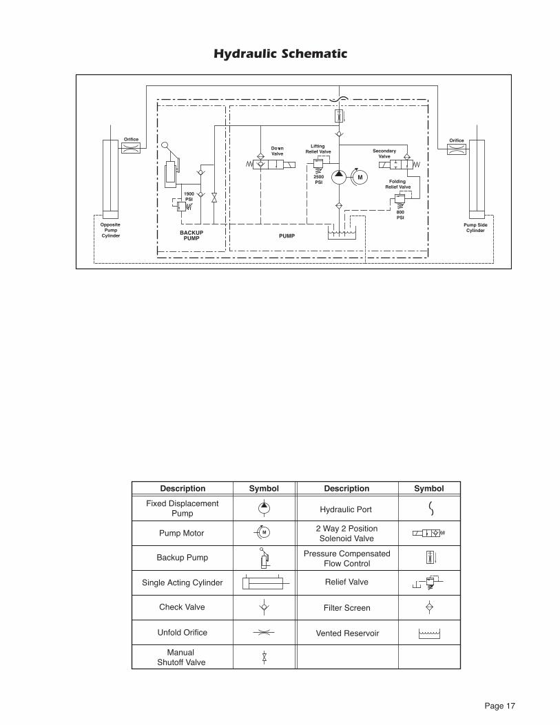
Orifice
Pump SideCylinderBACKUP
PUMP
2500PSI
DownValve
1900PSI
PUMP
Opposite Pump
Cylinder
M
Orifice
800PSI
SecondaryValve
Folding Relief Valve
Lifting Relief Valve
Fixed DisplacementPump
Vented Reservoir
Backup Pump
Single Acting Cylinder
Check Valve
Manual Shutoff Valve
2 Way 2 PositionSolenoid Valve
Pressure CompensatedFlow Control
Relief Valve
Description Symbol Description Symbol
Filter Screen
Unfold Orifice
MPump Motor
Hydraulic Port
Hydraulic Schematic

Page 18
Hydraulics Parts List
Item Qty. Description Part #
1 1 Pump Assembly (M-268-0114) 120G / 12V / Dual Relief 32858-12V
2 1 Solenoid, 4-Post Trombetta - Angle 35310
3 1 Motor, Pump - 12 Volt - Low RPM 29690
4 1 Valve Assembly, “Dual Relief" (complete) 31120K
5 1 Cartridge (only), “Dual Relief" Valve - (shown below) 31121
6 2 Coil (only) - (shown below) 31122
7 1 Valve Assembly, “Down” (complete) 31348K
8 1 Cartridge (only), “Down” Valve - (shown below) 26078
9 3 Screw, 1/4-20 x 2-1/4", Allen Head 26080
10 1 Hand Pump (Backup) with O-Rings (Item 11) 26074
11 4 O-Ring (only), Hand Pump Mounting 17351
12 1 Clamp, Reservoir - H-48 (M259) 17069
13 1 Reservoir, Hydraulic Fluid 30160
14 1 Cap, Reservoir Filler - Screw On 30167
15 1 Fitting, 90° - 1/8" NPT x 1/8" Barb - Plastic 87563
16 1 Clamp, Hose - Solenoid Mounting 29663
17 1 Hose, Thermal Plastic - Black, 1/8" I.D. 23742R* (6")
18 1 Handle with Grip 17206A
19 1 Fitting, Male 7-16-20 SAE O-Ring to Male 7/16-20 JIC 37° 24504
20 1 Elbow, 7/16-20 JIC 37 Female Swivel (1) - 7/16-20 JIC 37° Male (2) 26579
21 1 Hose Assembly, 1/8" (Opposite-Pump-Side) 16004A-090
22 1 Hose Assembly, 1/8" (Pump-Side) 16004A-051
24 2 Cylinder C1516.5-0409
25 2 Elbow, 90°, 1/4 NPT Male to 1/4" Barbed 15150
26 1 Hose, Thermal Plastic - Black, 1/8" I.D. 23742R* (68")
27 1 Hose, Thermal Plastic - Black, 1/8" I.D. 23742R* (30")
28 1 Diode Assembly, Up Solenoid 73906A
29 1 Kit, Hydraulic Port Service Cap 27049K
30 1 Connector, Plastic “Y”, 1/8” O.D. 18877
Seal Kits: If repairing a cylinder, order Seal Kit #1500-0500P.
5
Cartridge#31121
6
Coil#31122
“Dual Relief” Valve (complete)
4
8Cartridge#26078
6
Coil#31122
“Down” Valve (complete)
7
Hydraulic Fluid
When adding or changing
32840-QT (Exxon® Univis
not mix with Dextron III or

Page 19
24
Op
po
site
Pu
mp
Cyl
ind
er Manual BackupPump
2122
18
912
24
20
19
27
30
16
13
3
10
26
25
HydraulicPump Motor
Pu
mp
Sid
e C
ylin
der
7
414
17
15
25
23 23
11
1
29
HydraulicRepair
For repair of ahydraulic hoseor cylinder, readthis.
ServiceBulletin27049
2
28
Hydraulics Diagram

Page 20
Item Qty. Description NCL954FIB-2 NCL954IB-2 1 Pump Module (complete), 12 Volt, Rear 954-5516FNA 954-5516RNA 1 1 Pump Assembly (M268-0114) 12V-120G - Dual Relief (Includes Items 1, 2 & 20) 32858-12V 32858-12V 2 1 Solenoid, Up - 4-Post Trombetta - Angle 35310 35310 3 1 Housing, Pump (Complete Assembly 947-2513RNA (Rear) or 947-2513FNA (Front) Includes Items 3 - 21) 947-2513FN 947-2513RN 4 1 Beeper, Constant - High Output 33251 33251 5 1 Switch, Toggle w/ Gold Contacts 31787 31787 6 1 Stud, Power Feed 26084 26084 7 1 Lens, Threshold Warning - Red 30704 30704 8 1 Spacer, Lens - NHTSA 31386 31386 9 1 Metal Ring Base - Lamp 30971 30971 10 1 Socket, Lamp 30703 30703 11 3 Screw, #8-32 x 1/2" Pan Head Phillips - Thread Cut 30974 30974 12 1 Bulb, Light 19841 19841 13 2 Clamp, Spring - Pump Handle 12350 12350 14 4 Rivet, Pop, SD43BS - 1/8" - .13"/.19" 12954 12954 15 5 Rivet, Pop, SD62BS - 3/16" - .06"/.13" 11512 11512 16 1 Rivet, Snap, Black, 0.201" x .177/.217" 30408 30408 17 1 Screw, T-Head, 10-32 x 3/8", Thumb 33435 33435 18 1 Diode, Green LED - Panel Mount 29545 29545 19 1 Circuit Breaker, Manual Reset - 15 Amps 35143 35143 20 1 Clamp, Hose - Solenoid Mounting 29663 29663 21 3 Washer, #10 Flat 11541 11541 22 1 Elbow, Female Swivel 7/16-20 JIC 37° to (2) Male 7/16-20 JIC 37° 26579 26579 23 4 Rivet, Snap, .122" Dia. - .158 -.197" Thick 25759 25759 24 4 Washer, 5/16" External Tooth 16368 16368 25 2 Bolt, 5/16-18 x 3/4", Nylock, Hex * See note below 29608 29608 26 2 Bolt, 5/16-18 x 1/2", Nylock, Hex * See note below 10012 10012 27 1 Cover, Pump Module 947-2519FN 947-2519RN 28 1 Pump Handle with Grip 17206A 17206A 29 1 Cycle Counter, LCD w/o Reset 30547 30547 30 1 Flasher, 12V 32461 32461 31 2 Relay, 30/40A SPDT 12V with Internal Diode 35249 35249 32 1 Diode Assembly, Up Solenoid 73906A 73906A 33 1 Cable, Pump Module Power 26082A-4 26082A-4 34 1 Harness, Main 945-2500NA 945-2500NA 35 1 Fitting, Male 7/16-20 O-Ring to Male 7/16-20 JIC 37° 24504 24504 36 1 Cable, Lift / Chassis Ground 22166A 22166A 37 1 Wire Assembly, Lift Interlock Connection 31797A 31797A 38 1 Wire Assembly, Lift Stowed Connection See note below 31798A 31798A 39 1 Rubber Boot, Red See note below 82046 82046 40 1 Control, Hand Pendant Assembly - Non Electronic / Non Shielded - Coiled See note below 33659A 33659A 41 1 Harness, Lift Power See note below 33688A 33688A 42 1 Harness, Tower / Opposite Platform (Not shown - see Wiring Diagram) 37009A 37009A 43 1 Harness, Bridge Inputs - Platform (Not shown - see Wiring Diagram) 33373FA-954 33373RA-954 44 1 Harness, Stow - Platform (Not shown - see Wiring Diagram) 33377FA-954 33377RA-954 45 1 Harness, Tower / Pump - Platform (Not shown - see Wiring Diagram) 37014A 37014A 46 1 Harness, Extension Lighting - 61.5" (Not shown - see Wiring Diagram) 31033A61.5 31033A61.5 47 1 Harness, Extension Lighting - 103.5" (Not shown - see Wiring Diagram) 31033A103.5 31033A103.5 48 1 Hose Assembly, 90" - 1/8" Dia. - Swivel Ends (Not shown - see Hydraulic Diagram) 16004A-090 16004A-090 49 1 Hose Assembly, 51" - 1/8" Dia. - Swivel Ends (Not shown - see Hydraulic Diagram) 16004A-051 16004A-051 50 1 Hose, 1/8" Thermal Plastic (Not shown - see Hydraulic Diagram) 23742R 23742R 51 1 Kit, Hydraulic Port Service Cap (Not shown - see Hydraulic Diagram) 27049K 27049K 52 1 Decal, Warning / Pressure Relief Valve (Not shown - see Decal Section) See note below 22249 22249 53 1 Decal, Lift Power - On/Off (Not shown - see Decal Section) See note below 21494 21494 54 1 Decal, Dual Relief Valve Adjustment (Not shown - see Decal Section) See note below 32201 32201 55 1 Decal, Manual Instructions - Public (Not shown - see Decal Section) See note below 32940 32940
Pump Module Parts List
* Apply Loctite® Threadlocker Red 271™or equivalant to the three pump mounting bolts (items 25 and 26) if a blue
Indicates items available for replacement part purposes only. These items are not included with replacement pump modules.

Page 21
Pump Module Diagram
12
11
24
26
29
27
14
14
19
14
26
36
4
28
40
17
13
13
23
3941
37
34
38
15
15
15
5
15
33
35
34
7
31
30
9
10
34
34
21
34
8
22
6
6
14
25243
18
21
1
24
16
UPDOWN32819
FOLDUNFOLD
32820®
32
20
2
Pump Mounting Bolts
Apply Loctite®Threadlocker Red 271™ or equivalant to the three pump mount-ing bolts (items 25 and 26) if a blue nylon patch is not present on the bolts
-sembly.
Note: Rear pump module shown, front pump module mirror image.

Page 22
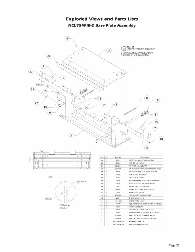
17
1
1
2
MICRO SWITCH ASSY975-4121A2
WMT-BASE-REAR/54" FTG954-0154RNW34
NOTE:
SPRING-DAMP5.67 E/4.291 C,P1=3.37N-RET
2 ASSY-THRESHOLD-STRIP SWITCH-NHTSA/94533337A
9
27208FW
945-2148KS-34Y
26963
4
3
2
1
7
6
5
1
1
1
2
KIT-BASE COVER - 34"
WMT-LATCH-LIFT-TITE FRONT-RETRO
8
4 24440 BOLT-5/16-18 X 3/4-BHSC/AUTO-BK
13
12
11
10
16
15
14
17
27208RW1 WMT-LATCH-LIFT-TITE REAR-RETRO
CABLE TIE-11" SOLID100914
4 26614
2 28339BK
2 11913
4 24570
3 29729
2 31816
O-RING 5/16 ID X 1/16
NUT-3/8-16 TOP LOCK/AUTO-BK
WASHER-1/2" NYLON
RING-5/16 EXT SNAP/ZINC PLATED
BOLT-3/8-16 X 1/2 W/NYLOCK PATCH
BOLT-SHOULDER, 5/16 X 5/8-1/4-20 SS W/PC
DETAIL A(SCALE = 4X)
"A"
NOTE:
NOTE:
19
18
2
2
2
CLAMP-INSULATED-1 3/8"29765
RIV-POP-SD66BS-3/16"-.25/.38/AUTO-BK14993
WASHER-#10 FLAT/AUTO-BK11541
2 WASHER-5/16 FLAT10063
1
6
9
3
45
10
13
7
11
15
8
18
1419
12
21
DESCRIPTIONPART NO.ITEM QTY.
1
4
4
4
PIN-PIVOT PARALLEL ARM
KIT-THRESHOLD TRANSITION-RUBBER NOSE
WASHER-1/2" FLAT-BK
SCREW-5/16-18 X 3/4" FHS/AUTO-BK
936-0403
36075KS
25346
25527
20
21
23
22
DWG. NOTES1) LOOP TAPESWITCH WIRE BACK AND SECURE WITH WIRE TIE 4X.2) TRIM AND TUCK WIRE TIE CLASP INTO HOLE 4X.3) APPLY LOCTITE® THREADLOCKER RED 271™ OR EQUIVALANT TO ALL #25527 SCREWS.
16
2
20
23
22
3NOTE:
Exploded Views and Parts ListsNCL954IB-2 Base Plate Assembly
Page 23
Exploded Views and Parts ListsNCL954FIB-2 Base Plate Assembly
17
1
1
2
MICRO SWITCH ASSY975-4121A2
WMT-BASE-FRONT/54" FTG954-0154FNW34
NOTE:
SPRING-DAMP5.67 E/4.291 C,P1=3.37N-RET
2 ASSY-THRESHOLD-STRIP SWITCH-NHTSA/94533337A
9
27208FW
945-2148KS-34Y
26963
4
3
2
1
7
6
5
1
1
1
2
KIT-BASE COVER - 34"
WMT-LATCH-LIFT-TITE FRONT-RETRO
8
4 24440 BOLT-5/16-18 X 3/4-BHSC/AUTO-BK
13
12
11
10
16
15
14
17
27208RW1 WMT-LATCH-LIFT-TITE REAR-RETRO
CABLE TIE-11" SOLID100914
4 26614
2 28339BK
2 11913
4 24570
3 29729
2 31816
O-RING 5/16 ID X 1/16
NUT-3/8-16 TOP LOCK/AUTO-BK
WASHER-1/2" NYLON
RING-5/16 EXT SNAP/ZINC PLATED
BOLT-3/8-16 X 1/2 W/NYLOCK PATCH
BOLT-SHOULDER, 5/16 X 5/8-1/4-20 SS W/PC
DETAIL A(SCALE = 4X)
NOTE:
NOTE:
19
18
2
2
2
CLAMP-INSULATED-1 3/8"29765
RIV-POP-SD66BS-3/16"-.25/.38/AUTO-BK14993
WASHER-#10 FLAT/AUTO-BK11541
2 WASHER-5/16 FLAT10063
1
6
9
3
4
5
10
13
7
818
1419
15
12
11
21
"A"
DESCRIPTIONPART NO.ITEM QTY.
1
4
4
4
PIN-PIVOT PARALLEL ARM
KIT-THRESHOLD TRANSITION-RUBBER NOSE
WASHER-1/2" FLAT-BK
SCREW-5/16-18 X 3/4" FHS/AUTO-BK
936-0403
36075KS
25346
25527
20
21
23
22
DWG. NOTES1) LOOP TAPESWITCH WIRE BACK AND SECURE WITH WIRE TIE 4X.2) TRIM AND TUCK WIRE TIE CLASP INTO HOLE 4X.3) APPLY LOCTITE® THREADLOCKER RED 271™ OR EQUIVALANT TO ALL #25527 SCREWS.
22
23
3NOTE:
16
2
20

Page 24
Exploded Views and Parts ListsTop Parallel Arm Assembly - Front
Top Parallel Arm Assembly - Rear
2
4
5
3
1
2401142
11 954-0419RNA
BEARING-FLANGE-3/4" X 3/8"-12FDU06
ASSY-PARALLEL ARM/TOP/54" FTG/R (Incl. Items 1-15)
3 4 34398 WASHER-0.906"ID X 1.25"OD X .075"TH/ZINC
4
5
1 945-0450 CAP-PARALLEL ARM
2 11513 RIV-POP-SD64BS-3/16"-.13/.25/AUTO-BK
6 1 915-0703 BRACKET-INNER SIDE PANEL GUIDE
7 1 14993 RIV-POP-SD66BS-3/16"-.25/.38/AUTO-BK
28593A19
18 955-2392CLXT
ASSY-BLOCK-GUIDE-PLATFORM-STOW
BKT.-QUIET-RIDE MTG.-955
10 1 24440 BOLT-5/16-18 X 3/4-BHSC/AUTO-BK
DESCRIPTIONPART NO.QTY.ITEM
11
12
1 16368 WASHER-5/16" EXTERNAL TOOTH
1 15858BK BOLT-CARR 5/16-18 X 3/4/AUTO-BK
13 1 10068 WASHER-5/16" LOCK/AUTO-BK
14 1 30996BK NUT-5/16-18 ACORN
15 1 10062 NUT-5/16-18 HEX/AUTO-BK
1
10
7
11
14
13
15
8
9
6
12
2
1
6
12
4
5
3
78
9
10
11
1513
14
2401142
11 954-0419FNA
BEARING-FLANGE-3/4" X 3/8"-12FDU06
ASSY-PARALLEL ARM/TOP/54"FTG (Incl. Items 1-15)
3 4 34398 WASHER-0.906"ID X 1.25"OD X .075"TH/ZINC
4
5
1 945-0450 CAP-PARALLEL ARM
2 11513 RIV-POP-SD64BS-3/16"-.13/.25/AUTO-BK
6 1 915-0703 BRACKET-INNER SIDE PANEL GUIDE
7 1 14993 RIV-POP-SD66BS-3/16"-.25/.38/AUTO-BK
28593A19
18 955-2392CLXT
ASSY-BLOCK-GUIDE-PLATFORM-STOW
BKT.-QUIET-RIDE MTG.-955
10 1 24440 BOLT-5/16-18 X 3/4-BHSC/AUTO-BK
DESCRIPTIONPART NO.QTY.ITEM
11
12
1 16368 WASHER-5/16" EXTERNAL TOOTH
1 15858BK BOLT-CARR 5/16-18 X 3/4/AUTO-BK
13 1 10068 WASHER-5/16" LOCK/AUTO-BK
14 1 30996BK NUT-5/16-18 ACORN
15 1 10062 WASHER-1/4" FLAT/AUTO-BK
Page 25
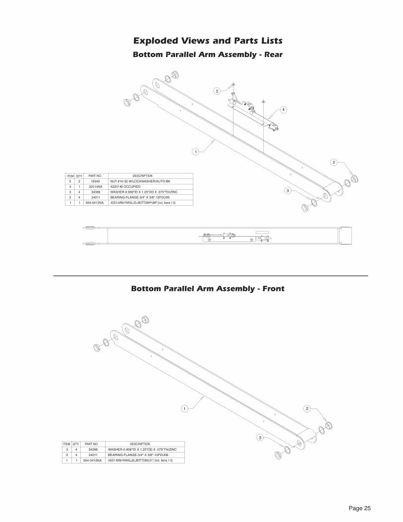
Exploded Views and Parts ListsBottom Parallel Arm Assembly - Rear
Bottom Parallel Arm Assembly - Front
1 2
3
ASSY ARM-PARALLEL/BOTTOM/L917 (Incl. Items 1-3)1
DESCRIPTIONQTY.ITEM PART NO.
954-0412NA1
2 BEARING-FLANGE-3/4" X 3/8"-12FDU064 24011
WASHER-0.906"ID X 1.25"OD X .075"TH/ZINC3 343984
1
2
3
5
4
WASHER-0.906"ID X 1.25"OD X .075"TH/ZINC343984
ASSY-ARM-PARALLEL/BOTTOM/PUMP (Incl. Items 1-3)
BEARING-FLANGE-3/4" X 3/8"-12FDU06
ASSY-IB OCCUPIED4
3
2
1
32514NA1
954-0412NA
240114
1
ITEM PART NO.QTY. DESCRIPTION
NUT-#10-32 W/LOCKWASHER/AUTO-BK5 183492

Page 26
Exploded Views and Parts ListsHydraulic Cylinder Assembly - Main
1
3
2
RETRACTED
EXTENDEDSTROKE 16.499
48.716
32.217
CYLINDER-16.499"/32.217 RETRACTED
ELBOW-1/4 NPT 90° 1/4 BARB
ELBOW-7/16-20 M/O-RNG/37*/.035 ORFICE
15150
26667
C1516.5-0409
3
2
1 1
1
1
DESCRIPTIONPART NO.ITEM QTY.
30° ±10°

Page 27
Exploded Views and Parts Lists
Vertical Arm Assembly - Rear
Vertical Arm Assembly - Front
945-5353
1000-2395A
31062A
954-0454RNW
4 1
2 1
11
7
5
1
1
ROLLER ASSY-ARM-TORQUE SHAFT
ASSY-LIGHT-VERTICAL CHANNEL w/BULB
WMT-VERTICAL CHANNEL-REAR-54"
RETAINER-LIFT TITE ROLLER
32408 RUBBER BUMPER-VERT CHAN.
8 1
9 2
33689A ASSY-BRIDGE SWITCH W/ HARN/NL/NCL-2
37049 SCREW-#4-40 X 3/8" THREAD FORM
10
11
12
3 936-0403 PIN-PIVOT PARALLEL ARM
3 25346 WASHER-1/2" FLAT/AUTO-BK
3 25527 SCREW-5/16-18 X 3/4" FHS/AUTO-BK
13
81064-000
PART NO.QTY.ITEM DESCRIPTION
6 1 SCREW-1/4-20 X 1" BHCS SS
310603 1 BULB-LIGHT-20W-HALOGEN REFLECTOR
DWG. NOTES1) INSERT SOCKET OF LIGHT ASSY THRU TOP KEY WHILE INSTALLING LIGHT. TIGHTEN SCREWS.
2) HARNESS TO BE TUCKED INSIDE CHANNEL.
3) APPLY LOCTITE® THREADLOCKER BLUE 242®
OR EQUIVALENT
4) APPLY LOCTITE® THREADLOCKER RED 271™ OR EQUIVALENT TO ALL #25527 SCREWS.
8 NOTE: 2
9
NOTE: 4
45
1
6
NOTE: 1
12
11
NOTE: 3
3
10
13
13
10
10
2
7
12
11
12
11
13
13
"A"
DETAIL A4 30063 RIVET-PUSH IN-8MM
945-5353
1000-2395A
31062A
954-0454FNW
4 1
2 1
11
6
5
1
1
ROLLER-ASSY-ARM-TORQUE SHAFT
ASSY-LIGHT-VERTICAL CHANNEL w/BULB
WMT-VERTICAL CHANNEL-FRONT-54"
RETAINER-LIFT TITE ROLLER
PART NO.QTY.ITEM DESCRIPTION
81064-000 SCREW-1/4-20 X BHCS SS
7 1 32408 RUBBER BUMPER-VERT CHAN.
8 3 936-0403 PIN-PIVOT PARALLEL ARM
9 3 25346 WASHER-1/2" FLAT/AUTO-BK
10
11
3 25527 SCREW-5/16-18 X 3/4" FHS/AUTO-BK
310603 1 BULB-LIGHT-20W-HALOGEN REFLECTOR
1
7
5
4
8
8
8
11
NOTE: 1
6 NOTE: 2
NOTE: 3
3
2
10
9
10
11
11
11
9
10
9
DWG. NOTES1) INSERT SOCKET OF LIGHT ASSY THRU TOP KEY WHILE INSTALLING LIGHT. TIGHTEN SCREWS.
2) APPLY LOCTITE® THREADLOCKER BLUE 242® OR EQUIVALENT
3) APPLY LOCTITE® THREADLOCKER RED 271™ OR EQUIVALENT TO ALL #25527 SCREWS.
4 30063 RIVET-PUSH IN-8MM
Page 28
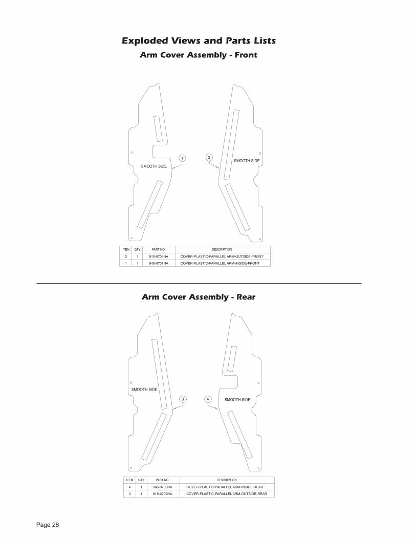
Exploded Views and Parts ListsArm Cover Assembly - Front
Arm Cover Assembly - Rear
4
1
11 945-0701NA COVER-PLASTIC-PARALLEL ARM-INSIDE-FRONT
SMOOTH SIDE
COVER-PLASTIC-PARALLEL ARM-INSIDE-REAR945-0703NA4 1
SMOOTH SIDE3
COVER-PLASTIC-PARALLEL ARM-OUTSIDE-REAR915-0702NA3 1
SMOOTH SIDE
SMOOTH SIDE2
DESCRIPTIONPART NO.QTY.ITEM
12 915-0704NA
DESCRIPTIONPART NO.QTY.ITEM
COVER-PLASTIC-PARALLEL ARM-OUTSIDE-FRONT

Page 29
Exploded Views and Parts ListsFront Handrail Assembly
Rear Handrail Assembly
1
3
4
6
7
8
12
9
11
10
5
7
6
5
4
3
1 1 954-0618NA HANDRAIL ASSY-NHTSA
QTY.ITEM PART NO. DESCRIPTION
12
11
10
8
9
14
1
1
2
1
2
1
1
1
2
1
10027 BOLT-3/8-16 X 2" HEX HD. CAP
18657 RING-3/4 EXT SNAP/AUTO-BK
900-0413N PIN-PIVOT LOWER ARM
915-2606N SLIDE-PLATFORM ROTATE
31677 SLIDE-UHMW-PLATFORM SLIDE-2X6.9"
11513 RIV-POP-SD64BS-3/16"-.13/.25/AUTO-BK
954-0640RNA ASSY-FOLD ARM-48 FTG-REAR
13617 NUT-3/8-16 UNC HEX LOCK/AUTO-BK
30227 SPACER-UHMW 0.75 OD X 0.39 ID X 0.25
29186A GAS SPRING ASSY-14.468 EXT/8.956 COMP
1 * 32519A SWITCH ASSEMBLY (INCLUDED WITH ITEM 9)
* INDICATES ITEMS NOT SHOWN
2
13 1
1
213
10069
25171
WASHER-3/8" LOCK
BOLT-3/8-16 X 3/4" FLBHSCS-GD8
6
8
10
11
1
3
4
9
5
6
5
4
3
1
QTY.ITEM PART NO. DESCRIPTION
11
10
8
9
1
1
2
1
2
1
1
1
10027 BOLT-3/8-16 X 2" HEX HD. CAP
18657 RING-3/4 EXT SNAP/AUTO-BK
900-0413N PIN-PIVOT LOWER ARM
915-2606N SLIDE-PLATFORM ROTATE
954-0640FNA ASSY-FOLD ARM-48 FTG-FRONT
13617 NUT-3/8-16 UNC HEX LOCK/AUTO-BK
30227 SPACER-UHMW 0.75 OD X 0.39 ID X 0.25
29186A GAS SPRING ASSY-14.468 EXT/8.956 COMP
1 954-0618NA HANDRAIL ASSY-NHTSA
7
13
7 1 31677 SLIDE-UHMW-PLATFORM SLIDE-2X6.9"
13 2 11513 RIV-POP-SD64BS-3/16"-.13/.25/AUTO-BK
212
10069
25171
WASHER-3/8" LOCK
BOLT-3/8-16 X 3/4" FLBHSCS-GD82
12
1
1

Page 30
Exploded Views and Parts ListsNCL954IB-2 & NCL954FIB-2 Platform Assembly
BEARING-FLANGE-1 X 1/2-16FDU084 2803112
RING-3/8 RETAINING SNAP1388929
PLATFORM-NCL919IB 54" FTG1 1 954-33454NW
ASSY-ROLL STOP w/RUBBER/-212 945-3312NA34Y
STOP-PLATFORM23 900-0311
BKT-LATCH/ROLL STOP/REAR16 945-3202RN
ROLL STOP ACTIVATION FOOT17 945-0200NW-34
4 81003-0002 SCREW-5/16-18 X 1 1/4 SHCS BK ZINC
107754 NUT-1/4-20 HEX LOCK/AUTO-BK25
48 29371 WASHER-THRUST-.875 OD/.50 ID/.0585T
26 2 945-2336N BEARING-PLATFORM SLIDE
15 945-3202FN BKT-LATCH/ROLL STOP/FRONT
10 ASSY ROLL STOP LATCH/OCCUPIED SWITCH1 945-5206RNA
11 LATCH-ROLL STOP/FRONT1 945-5206FN
13 BEARING-PLASTIC-FLANGE-3/8IDX1/4"6 24028
14 STANDOFF-FOOT MOUNT2 32759
15 SCREW-10-32 X 1.25" SHCS2 40-1092-0
16 BOLT-5/16-18 X 1" HEX HD. CAP2 10013
27 4 15733 BOLT-1/4-20 X 1/2" BUT HD SOC/AUTO-BK
28 2 32831 GAS-SPRING-30LB-3.54X9.65
29 1 954-0147NW34Y BRIDGE PLATE WELDMENT-34/54" FTG (954-0147NA34Y INCL. 29, 36-46)
30 2 28324BK NUT-5/16-18 TOP LOCK/AUTO-BK
CABLE TIE 3 3/4" BLACK431 91010-000 *
17 NUT-5/16-18 HEX/AUTO-BK2 10058
990-034122 2 ADAPT-CYL/ROLL STOP LEVER-OUT
40-4230-0
18663
24
223
4
SCREW-1/2-20 X 1.5 SET-LOCK/AUTO-BK
SCREW-1/4-20 X 5/8" FHSC
19 2 24932BK PIN-CLEVIS 3/8 X 3" EFF LEN.-W/O HOLE/BK
21 4 24537 SCREW-#10-32X3/8 FL HD-HX SKT/AUTO-BK
18 BRACKET ADJUST-SPLIT FOOT2 33411
20 2 34686 PIN-ROLLSTOP GAS SPRING
DECAL-BOUNDARY YELLOW LEXAN 1" x 39 1/2"232 30236R039.5
DECAL-BOUNDARY YELLOW LEXAN 1" x 33 1/2"133 30236R033.5
HAIRPIN COTTER-STAINLESS-.042234 36003
PART NO.QTY.ITEM DESCRIPTION
* ITEMS NOT SHOWN
DECAL-BOUNDARY YELLOW LEXAN 1" X 11"235 30236R011
BOLT-3/8-16 x 3/4" FLBHSCS-GD8436 25171
BEARING-FLANGE-3/4" X 1/4"-12FDU04237 24012
NUT-1/4-20 NYLOCK-ZINC238 14614Z
RUBBER BUMPER-VERT CHAN.140 32408
NUT-3/8-16 HEX/AUTO-BK441 10059BK
BUMPER-1" X 5/8" LG NAT UHMW/BRIDGEPLATE 242 33603
BOLT-1/4-20 X 1" HEX243 10001
WMT-BKT-BRIDGE PLATE/RR144 945-0431RNW
BEARING-UHMW FLAT-THIN-BLK345 916-5406
WMT-BKT-BRIDGE PLATE/FR146 945-0431FNW
WASHER-3/8" LOCK/AUTO-BK439 10069BK
PART NO.QTY.ITEM DESCRIPTION
3
29
2330
12
12
30
23
12
27
28
24
7
20
14
13
19
13
15
1617
18
25
626
25
89
3
4
1
4
12
21
21
34
221NOTE:
1NOTE:
1NOTE:
2NOTE:
33 32
35
3NOTE: 4NOTE:
34
DWG. NOTES
1) USE LOCTITE® THREADLOCKER RED 271™ OR EQUIVALENT ON SCREWS (B.C. #24537 AND B.C. 157332) USE LOCTITE® THREADLOCKER GREEN 290™ OR EQUIVALENT ON CLEVIS PINS (B.C. #24932BK)3) APPLY BOUNDARY DECAL (ITEM 33) 48 1/8" FROM FRONT EDGE OF PLATFORM TO LEADING EDGE OF DECAL.4) INBOARD EDGE OF DECAL (ITEM 32) TO BEGIN AT 48 1/2"
36
45
45
43
394142
46
38
37
44
43
42
41
39
40
38 37
45
36
34
20
11
8

Page 31
WARRANTY COVERAGE AND WARRANTY COVERAGE TIME PERIODS
The Braun Corporation (“Braun”) warranty covers certain parts of this wheelchair lift for three (3) years or 10,000 cycles and the cost of labor to repair or replace those parts for one (1) year or 3,000 cycles. If The Braun Corporation receives the warranty registration card within 20 days after the lift is put into service, the warranty labor coverage will increase from one (1) year or 3,000 cycles to three (3) years or 10,000 cycles. In addition, providing the warranty registration card is returned as noted above, the following lift’s power
-tor, Pump, Hydraulic Hose and Fittings. This limited warranty covers substantial defects in materials and workmanship of the lift, provided that the lift is operated and maintained properly and in conformity with
purchaser by an independent, authorized dealer of Braun, or, if the dealer places the product into any type
WHAT BRAUN WILL DO TO CORRECT PROBLEMS
In the event that a substantial defect in material or workmanship, attributable to Braun, is found to exist
for parts or labor to the owner, in accordance with the terms, conditions and limitations of this limited war-ranty. If the substantial defect in material or workmanship, attributable to Braun, is found to exist during the second or third year of warranty coverage, it will be repaired or replaced, at Braun’s option, without charge to the owner for parts, only, in accordance with the terms, conditions and limitations of this limited warranty. Providing the warranty card is returned within 20 days as outlined above, the labor warranty period will be extended by two years of coverage in accordance with the terms, conditions, and limitations of this limited warranty. In addition, if a substantial defect in material or workmanship, attributable to Braun, is found
Cylinder, Flow Control, Gear Box, Motor, Pump, Hydraulic Hose and Fittings, it will be repaired or replaced, at Braun’s option, without charge to the owner for parts, only, in accordance with the terms, conditions and limitations of this limited warranty. The cost of labor for repair or replacement at any time after the warranty coverage detailed above is the sole responsibility of the owner.
Braun’s obligation to repair or replace defective materials or workmanship is the sole obligation of Braun under this limited warranty. Braun reserves the right to use new or remanufactured parts of similar quality to complete any work, and to make parts and design changes from time to time without notice to anyone. Braun reserves the right to make changes in the design or material of its products without incurring any obligation to incorporate such changes in any previously manufactured product. Braun makes no warranty as to the future performance of this product, and this limited warranty is not intended to extend to the future performance of the product. In addition, the owner’s obligation to notify Braun, or one of its authorized, independent dealers, of a claimed defect does not modify any obligation placed on the owner to contact Braun directly when attempting to pursue remedies under state or federal law.
LIMITATIONS, EXCLUSIONS AND DISCLAIMER OF IMPLIED WARRANTIES
ANY IMPLIED WARRANTY THAT IS FOUND TO ARISE BY WAY OF STATE OR FEDERAL LAW, IN-CLUDING ANY IMPLIED WARRANTY OF MERCHANTABILITY OR ANY IMPLIED WARRANTY OF FITNESS, IS LIMITED IN DURATION TO THE TERMS OF THIS LIMITED WARRANTY AND IS LIMITED IN SCOPE OF COVERAGE TO THE SCOPE OF COVERAGE OF THIS LIMITED WARRANTY. Braun
items excluded from coverage as set forth in this limited warranty. Braun makes no warranty of any nature beyond that contained in this limited warranty. No one has authority to enlarge, amend or modify this limited warranty, and Braun does not authorize anyone to create any other obligation for it regarding this product. Braun is not responsible for any representation, promise or warranty made by any independent dealer or other person beyond what is expressly stated in this limited warranty. Any selling or servicing dealer is not Braun’s agent, but an independent entity.
Braun® Limited Warranty

Page 32
BRAUN SHALL NOT BE LIABLE FOR ANY INCIDENTAL OR CONSEQUENTIAL DAMAGES THAT MAY RESULT FROM BREACH OF THIS LIMITED WARRANTY OR ANY IMPLIED WARRANTY. THIS EXCLUSION OF CONSEQUENTIAL AND INCIDENTAL DAMAGES SHALL BE INDEPENDENT OF ANY FAILURE OF THE ESSENTIAL PURPOSE OF ANY WARRANTY, AND THIS EXCLUSION SHALL SUR-VIVE ANY DETERMINATION THAT THIS LIMITED WARRANTY OR ANY IMPLIED WARRANTY HAS FAILED OF ITS ESSENTIAL PURPOSE. This warranty does not cover, and in no event shall Braun be liable for towing charges, travel, lodging, or any other expense incurred due to the loss of use of the product or other reason.
Some states do not allow limitations on how long an implied warranty lasts, or the exclusion or limitation of incidental or consequential damages, so the above limitations or exclusions may not apply to you.
HOW TO GET SERVICE
To obtain warranty service the owner must do all of the following:
1. Notify an authorized service center, of the claimed defect attributable to Braun, within the warranty cov-erage period designated above
should have discovered, the claimed defect 3. Promptly schedule an appointment with and take the product to an authorized service center for service.4. Pay any transportation costs and all expenses associated with obtaining warranty service.
Since Braun does not control the scheduling of service work at the independent dealerships you may en-counter some delay in scheduling or completion of work. If you need assistance you may contact Braun, at 631 West 11th Street, Winamac, Indiana 46996; 1-800-THE-LIFT, (843-5438).
If two (2) or more service attempts have been made to correct any covered defect that you believe impairs the value, use or safety of the product, or if it has taken longer than thirty (30) days for repairs to be com-pleted, you must, to the extent permitted by law, notify Braun directly, in writing, at the above address, of the unsuccessful repair(s) of the alleged defect(s) so that Braun can become directly involved in providing service pursuant to the terms of this limited warranty.
WHAT IS NOT COVERED This Limited Warranty does not cover any of the following: defects in materials, components or parts of the product not attributable to Braun, any material, component or part of the product that is warranted by another entity (Note: the written warranty provided by the manufacturer of the material, component or part is the direct responsibility of that manufacturer); items that are added or changed after the product leaves Braun’s possession; additional items installed at any dealership, or other place of business, or by any other party, other than Braun; normal wear, tear, usage, maintenance, service, periodic adjustments, the effects of condensation or moisture from condensation; mold or any damage caused by mold; imperfections that do not affect the product for its intended purpose; items that are working as designed but that you are unhappy with; problems related to mis-operation, misuse, mishandling, neglect or abuse, including failure to main-tain the product in accordance with the owner’s manual, or other routine maintenance such as inspections, lubricating, adjustments, tightening of screws, sealing, wheel alignments or rotating tires; damage due to accident or collision, including any acts of weather or damage or corrosion due to the environment; theft,
failure; defacing, scratches, dents or chips on any interior or exterior surface of the product, including those caused by rocks or other road hazards, damage caused by off road use, overloading or alteration of the product, or any of its components or parts.
Defects and/or damage to interior and exterior surfaces and other appearance items may occur at the fac-tory or when the product is in transit. These items are usually detected and corrected at the factory or by
Braun® Limited Warranty

Page 33
a dealer prior to delivery to the purchaser. You must inspect the product for this type of damage when you
of delivery to have these items covered by this limited warranty and to have work performed on the items at no cost to you as provided by this limited warranty.
EVENTS DISCHARGING BRAUN FROM OBLIGATION UNDER WARRANTY
The following shall completely discharge Braun from any express or implied warranty obligation to repair or replace anything and void this warranty: misuse, neglect, collision, accidents, failure to provide routine maintenance (See Owner’s Manual), unauthorized alteration, off road use, Acts of Nature, damage from
odometer tampering.
LEGAL REMEDIES
Any action to enforce any portion of this limited warranty, or any implied warranty, must be commenced within six (6) months after expiration of the warranty coverage period designated above or the action will be barred because of the passage of time. Any performance of repairs shall not suspend this limitation period from expiring. Any performance of repairs after the warranty coverage period has expired, or performance of repairs regarding any thing excluded from coverage under this limited warranty shall be considered “good will” repairs, and they will not alter the terms of this limited warranty, or extend the warranty coverage period
will need some service during the warranty period; this warranty does not extend to future performance. It only sets forth what Braun will do and does not guarantee anything about the product for any time period. Nothing in this warranty, or any action of Braun, or any agent of Braun, shall be interpreted as an extension
in the statute of limitations, so this reduction may not apply to you.
WARRANTY REGISTRATION and MISCELLANEOUS
Your warranty registration records should be completed and delivered to the appropriate companies, includ-ing the Braun Delivery Checklist & Warranty form. That form must be returned to Braun within twenty (20) days of purchase. The Braun warranty will not be registered unless this warranty registration is completed
this limited warranty as long as you can present proof of purchase, but it can cause delays in obtaining the
the product by Braun.
Braun agrees to repair or replace any of its factory installed parts found to have substantial defects within the appropriate warranty period designated above, provided that the repair is authorized by Braun and car-ried out by an authorized service center (a Braun labor schedule determines the cost allowance for repairs). Braun will not honor any warranty claim for repairs or replacement of parts unless the claim is submitted with the appropriate paperwork, and the work is completed by an independent, factory authorized service center. The appropriate paperwork can be obtained by written or phone contact with Braun at the contact information in this warranty.
Braun reserves the right to designate where any warranty work can be performed. Braun also reserves the right to examine any defective workmanship or part prior to giving any authorization for warranty work. Braun’s return authorization procedure must be adhered to in order to process any warranty claims.
THIS WARRANTY GIVES YOU SPECIFIC LEGAL RIGHTS. YOU MAY ALSO HAVE OTHER RIGHTS THAT VARY FROM STATE TO STATE.
Braun® Limited Warranty

Page 34
NOTESThis page intentionally left blank.

Over 300 Braun Dealers Worldwide
"Providing Access to the World"
®
"Providing Access to the World"
International Corporate Hdqrs: P.O. Box 310 Winamac, IN 46996 USA1-800-THE LIFT® (574) 946-6153 FAX: (574) 946-4670
®

"Providing Access to the World"®®
International Corporate Hdqrs: P.O. Box 310 Winamac, IN 46996 USA1-800-THE LIFT® (574) 946-6153 FAX: (574) 946-4670
NCL9
54
Cen
tury
2 Se
ries
NCL9
54
Cen
tury
2 Se
ries33220
© The Braun Corporation© The Braun Corporation
All illustrations, descriptions and specifications in this manual are based on the latest product information available at the time of publication. The Braun Corporation reserves the right to make changes at any time without notice.All illustrations, descriptions and specifications in this manual are based on the latest product information available at the time of publication. The Braun Corporation reserves the right to make changes at any time without notice.
2Century 2NCL954NCL954
SeriesSeriesPublic Use Wheelchair Lifts
Service Manual for:
FASeries FA
Patent #7,306,422
Patent #5,261,779
Patent #6,238,169
Patent #6,464,447
Patent #6,599,079
Patent #6,692,217
Patent #6,739,824
Patent #7,422,408
Patent #7,441,995
Patent #7,530,226
37717 Rev. AApril 201237717 Rev. AApril 2012