250 mA LED driver in SOT223 - Nexperia
18
NCR320Z / NCR321Z 250 mA LED driver in SOT223 Rev. 1 — 4 February 2019 Product data sheet 1. Product profile 1.1. General description LED driver consisting of a resistor-equipped NPN transistor with two diodes on one chip in a medium power SOT223 (SC-73) Surface-Mounted Device (SMD) plastic package. Table 1. Product overview Package Type number Nexperia JEITA NCR320Z SOT223 SC-73 NCR321Z SOT223 SC-73 1.2. Features and benefits • Stabilized output current of 10 mA without external resistor • Stabilized output current adjustable up to 250 mA when an external resistor is used • High current accuracy at supply voltage variation • Low voltage overhead of 1.4 V • Reduces component count and board space • High power dissipation of 1250 mW • Supply voltage up to 16 V • Digital PWM input up to 10 kHz frequency for NCR321Z • AEC-Q101 qualified 1.3. Applications • Constant current LED driver • Generic constant current source • Automotive applications (for example: interior lighting, dash board, instrumentation, number plate light) • Increase stabilized output current by paralleling drivers
Transcript of 250 mA LED driver in SOT223 - Nexperia
NCR320Z / NCR321Z250 mA LED driver in SOT223Rev. 1 — 4 February 2019 Product data sheet
1. Product profile
1.1. General descriptionLED driver consisting of a resistor-equipped NPN transistor with two diodes on one chip in amedium power SOT223 (SC-73) Surface-Mounted Device (SMD) plastic package.
Table 1. Product overviewPackageType numberNexperia JEITA
NCR320Z SOT223 SC-73
NCR321Z SOT223 SC-73
1.2. Features and benefits• Stabilized output current of 10 mA without external resistor• Stabilized output current adjustable up to 250 mA when an external resistor is used• High current accuracy at supply voltage variation• Low voltage overhead of 1.4 V• Reduces component count and board space• High power dissipation of 1250 mW• Supply voltage up to 16 V• Digital PWM input up to 10 kHz frequency for NCR321Z• AEC-Q101 qualified
1.3. Applications• Constant current LED driver• Generic constant current source• Automotive applications (for example: interior lighting, dash board, instrumentation, number
plate light)• Increase stabilized output current by paralleling drivers
Nexperia NCR320Z / NCR321Z250 mA LED driver in SOT223
1.4. Quick reference data
Table 2. Quick reference dataSymbol Parameter Conditions Min Typ Max Unit
enable voltage
NCR320Z - - 25 V
VEN
NCR321Z - - 4.5 V
Vout output voltage - - 16 V
stabilized output current
NCR320Z Vout= 1.4 V;VEN= 12 V
[1] 9 10 11 mA
Iout
NCR321Z Vout= 1.4 V;VEN= 3.3 V
[1] 9 10 11 mA
[1] Pulse test: tp ≤ 300 µs; δ ≤ 0.02
2. Pinning information
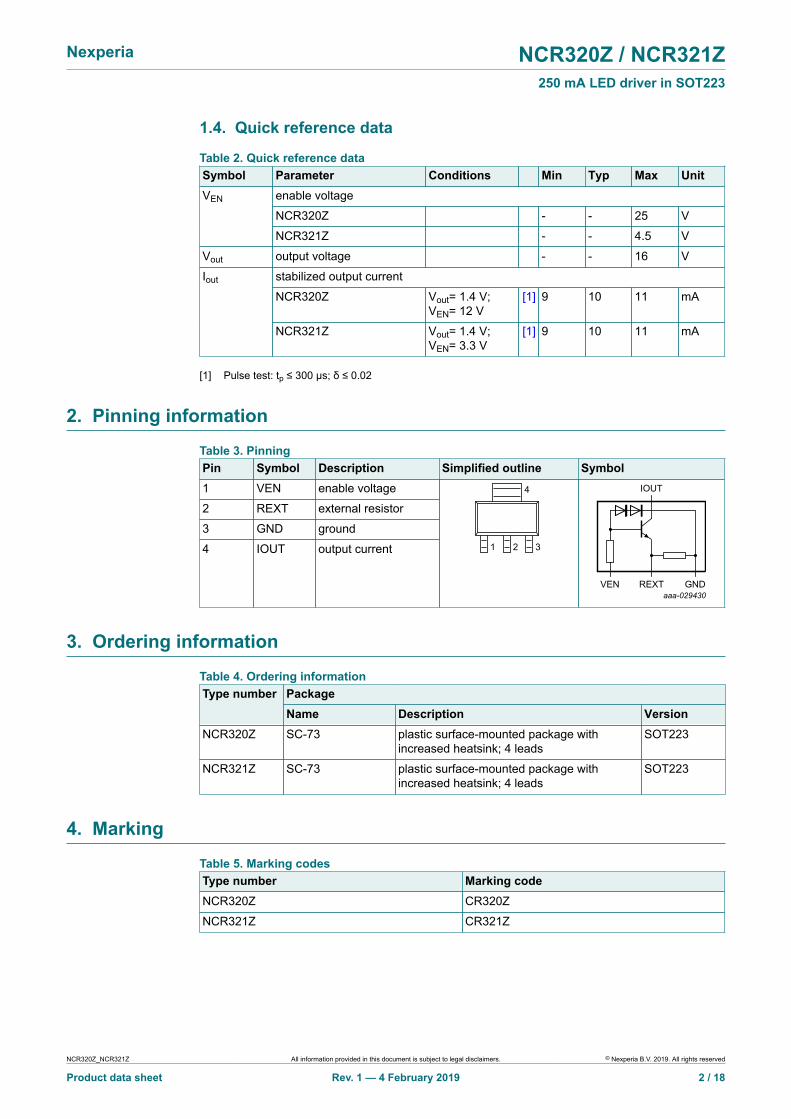
Table 3. PinningPin Symbol Description Simplified outline Symbol1 VEN enable voltage
2 REXT external resistor
3 GND ground
4 IOUT output current 1 32
4
aaa-029430VEN GNDREXT
IOUT
3. Ordering information
Table 4. Ordering informationPackageType numberName Description Version
NCR320Z SC-73 plastic surface-mounted package withincreased heatsink; 4 leads
SOT223
NCR321Z SC-73 plastic surface-mounted package withincreased heatsink; 4 leads
SOT223
4. Marking
Table 5. Marking codesType number Marking codeNCR320Z CR320Z
NCR321Z CR321Z
NCR320Z_NCR321Z All information provided in this document is subject to legal disclaimers. © Nexperia B.V. 2019. All rights reserved
Product data sheet Rev. 1 — 4 February 2019 2 / 18
Nexperia NCR320Z / NCR321Z250 mA LED driver in SOT223
5. Limiting values
Table 6. Limiting valuesIn accordance with the Absolute Maximum Rating System (IEC 60134).
Symbol Parameter Conditions Min Max UnitIout stabilized output current if
external resistor is used- 300 mA
enable voltage
NCR320Z - 25 V
VEN
NCR321Z - 4.5 V
Vout output voltage - 16 V
VR reverse voltage [1] - 0.5 V
[2] - 765 mW
[3] - 1160 mW
[4] - 1250 mW
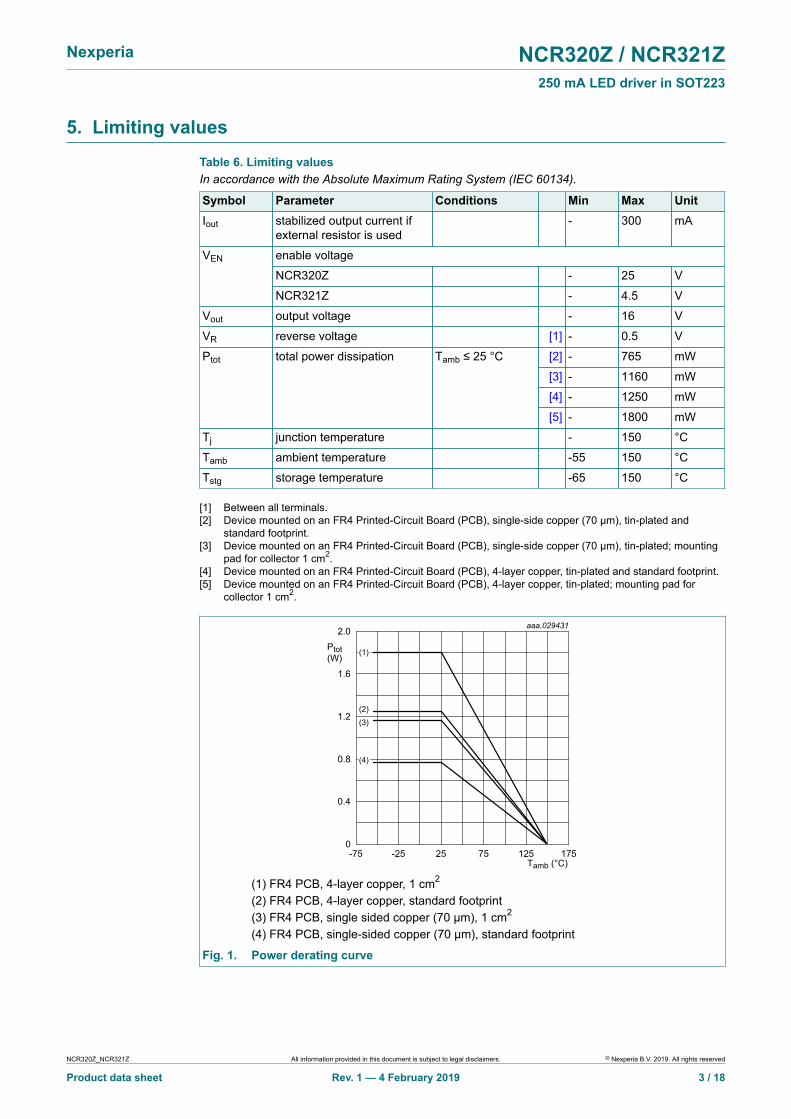
Ptot total power dissipation Tamb ≤ 25 °C
[5] - 1800 mW
Tj junction temperature - 150 °C
Tamb ambient temperature -55 150 °C
Tstg storage temperature -65 150 °C
[1] Between all terminals.[2] Device mounted on an FR4 Printed-Circuit Board (PCB), single-side copper (70 µm), tin-plated and
standard footprint.[3] Device mounted on an FR4 Printed-Circuit Board (PCB), single-side copper (70 µm), tin-plated; mounting
pad for collector 1 cm2.[4] Device mounted on an FR4 Printed-Circuit Board (PCB), 4-layer copper, tin-plated and standard footprint.[5] Device mounted on an FR4 Printed-Circuit Board (PCB), 4-layer copper, tin-plated; mounting pad for
collector 1 cm2.
Tamb (°C)-75 17512525 75-25
aaa.029431
0.8
1.2
0.4
1.6
2.0
Ptot(W)
0
(1)
(2)
(3)
(4)
(1) FR4 PCB, 4-layer copper, 1 cm2
(2) FR4 PCB, 4-layer copper, standard footprint(3) FR4 PCB, single sided copper (70 µm), 1 cm2
(4) FR4 PCB, single-sided copper (70 µm), standard footprint
Fig. 1. Power derating curve
NCR320Z_NCR321Z All information provided in this document is subject to legal disclaimers. © Nexperia B.V. 2019. All rights reserved
Product data sheet Rev. 1 — 4 February 2019 3 / 18
Nexperia NCR320Z / NCR321Z250 mA LED driver in SOT223
6. Thermal characteristics
Table 7. Thermal characteristicsSymbol Parameter Conditions Min Typ Max Unit
[1] - - 164 K/W
[2] - - 108 K/W
[3] - - 100 K/W
Rth(j-a) thermal resistance fromjunction to ambient
in free air
[4] - - 70 K/W
Rth(j-sp) thermal resistance fromjunction to solder point
- - 27 K/W
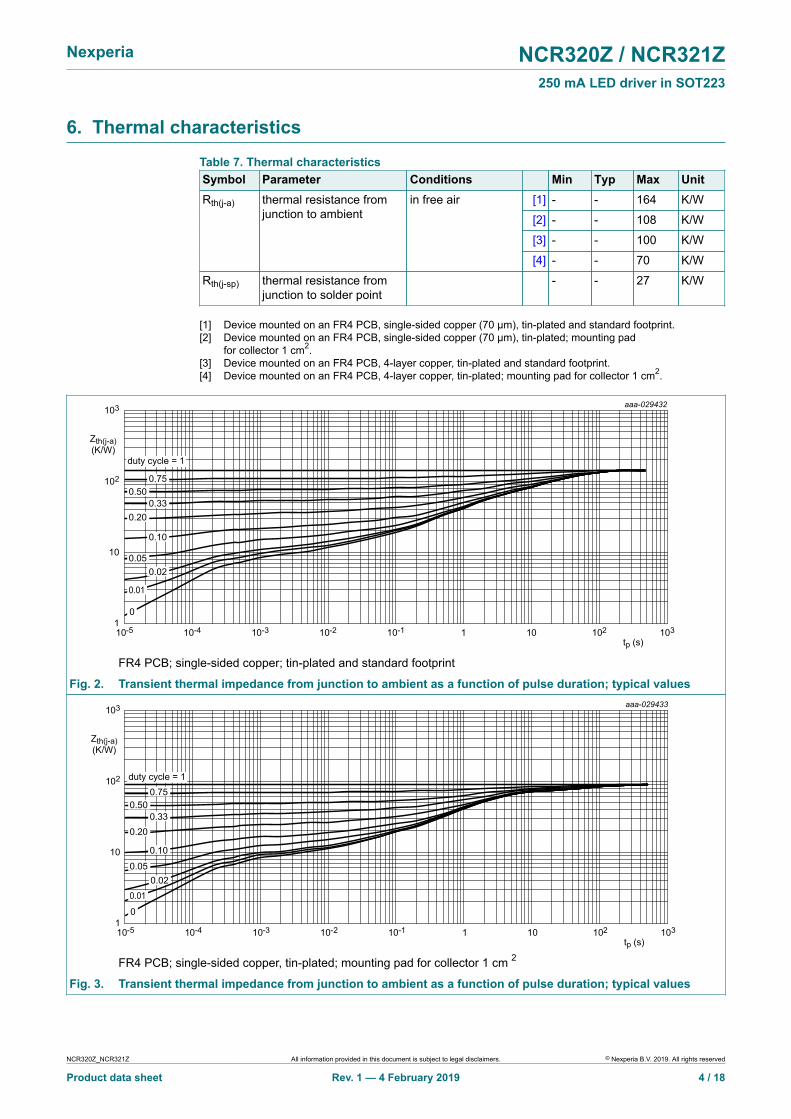
[1] Device mounted on an FR4 PCB, single-sided copper (70 µm), tin-plated and standard footprint.[2] Device mounted on an FR4 PCB, single-sided copper (70 µm), tin-plated; mounting pad
for collector 1 cm2.[3] Device mounted on an FR4 PCB, 4-layer copper, tin-plated and standard footprint.[4] Device mounted on an FR4 PCB, 4-layer copper, tin-plated; mounting pad for collector 1 cm2.
aaa-029432
10-5 1010-210-4 10210-1tp (s)
10-3 1031
102
10
103
Zth(j-a)(K/W)
10
0.020.05
0.33
0.75
duty cycle = 1
0.01
0.10
0.20
0.50
FR4 PCB; single-sided copper; tin-plated and standard footprint
Fig. 2. Transient thermal impedance from junction to ambient as a function of pulse duration; typical valuesaaa-029433
10-5 1010-210-4 10210-1tp (s)
10-3 1031
102
10
103
Zth(j-a)(K/W)
10
0.020.05
0.33
0.75duty cycle = 1
0.10
0.20
0.50
0.01
FR4 PCB; single-sided copper, tin-plated; mounting pad for collector 1 cm 2
Fig. 3. Transient thermal impedance from junction to ambient as a function of pulse duration; typical values
NCR320Z_NCR321Z All information provided in this document is subject to legal disclaimers. © Nexperia B.V. 2019. All rights reserved
Product data sheet Rev. 1 — 4 February 2019 4 / 18
Nexperia NCR320Z / NCR321Z250 mA LED driver in SOT223
aaa-029434
10-5 1010-210-4 10210-1tp (s)
10-3 1031
102
10
103
Zth(j-a)(K/W)
1
duty cycle = 1
0
0.020.05
0.33
0.10
0.20
0.01
0.750.50
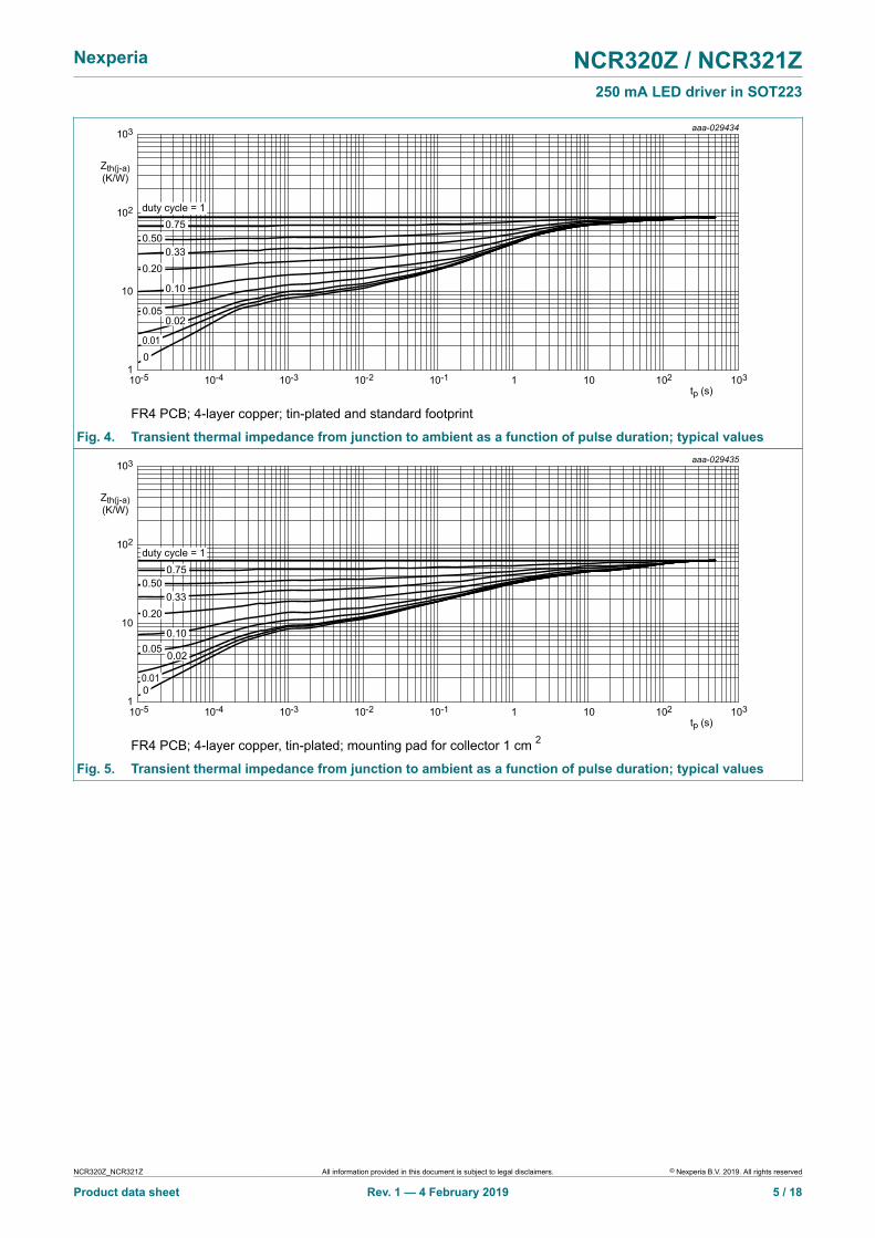
FR4 PCB; 4-layer copper; tin-plated and standard footprint
Fig. 4. Transient thermal impedance from junction to ambient as a function of pulse duration; typical valuesaaa-029435
10-5 1010-210-4 10210-1tp (s)
10-3 1031
102
10
103
Zth(j-a)(K/W)
1
duty cycle = 1
0.050.10
0.200.33
0.750.50
0.010
0.02
FR4 PCB; 4-layer copper, tin-plated; mounting pad for collector 1 cm 2
Fig. 5. Transient thermal impedance from junction to ambient as a function of pulse duration; typical values
NCR320Z_NCR321Z All information provided in this document is subject to legal disclaimers. © Nexperia B.V. 2019. All rights reserved
Product data sheet Rev. 1 — 4 February 2019 5 / 18
Nexperia NCR320Z / NCR321Z250 mA LED driver in SOT223
7. Characteristics
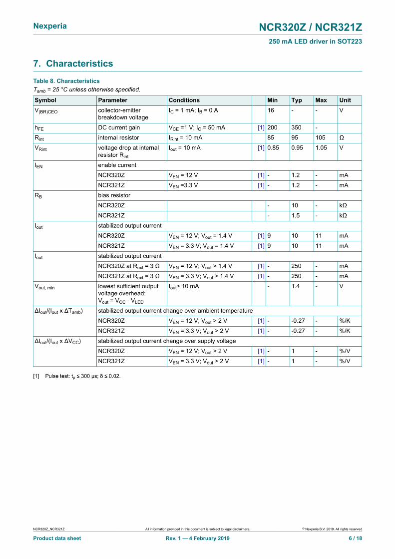
Table 8. CharacteristicsTamb = 25 °C unless otherwise specified.
Symbol Parameter Conditions Min Typ Max UnitV(BR)CEO collector-emitter
breakdown voltageIC = 1 mA; IB = 0 A 16 - - V
hFE DC current gain VCE =1 V; IC = 50 mA [1] 200 350 -
Rint internal resistor IRint = 10 mA 85 95 105 Ω
VRint voltage drop at internalresistor Rint
Iout = 10 mA [1] 0.85 0.95 1.05 V
enable current
NCR320Z VEN = 12 V [1] - 1.2 - mA
IEN
NCR321Z VEN =3.3 V [1] - 1.2 - mA
bias resistor
NCR320Z - 10 - kΩ
RB
NCR321Z - 1.5 - kΩ
stabilized output current
NCR320Z VEN = 12 V; Vout = 1.4 V [1] 9 10 11 mA
Iout
NCR321Z VEN = 3.3 V; Vout = 1.4 V [1] 9 10 11 mA
stabilized output current
NCR320Z at Rext = 3 Ω VEN = 12 V; Vout > 1.4 V [1] - 250 - mA
Iout
NCR321Z at Rext = 3 Ω VEN = 3.3 V; Vout > 1.4 V [1] - 250 - mA
Vout, min lowest sufficient outputvoltage overhead:Vout = VCC - VLED
Iout> 10 mA - 1.4 - V
stabilized output current change over ambient temperature
NCR320Z VEN = 12 V; Vout > 2 V [1] - -0.27 - %/K
ΔIout/(Iout x ΔTamb)
NCR321Z VEN = 3.3 V; Vout > 2 V [1] - -0.27 - %/K
stabilized output current change over supply voltage
NCR320Z VEN = 12 V; Vout > 2 V [1] - 1 - %/V
ΔIout/(Iout x ΔVCC)
NCR321Z VEN = 3.3 V; Vout > 2 V [1] - 1 - %/V
[1] Pulse test: tp ≤ 300 μs; δ ≤ 0.02.
NCR320Z_NCR321Z All information provided in this document is subject to legal disclaimers. © Nexperia B.V. 2019. All rights reserved
Product data sheet Rev. 1 — 4 February 2019 6 / 18
Nexperia NCR320Z / NCR321Z250 mA LED driver in SOT223
Vout (V)0 1284
aaa-029390
0.1
0.2
0.3
Iout(A)
0
(1)
(2)
(3)
(4)
(5)
(6)
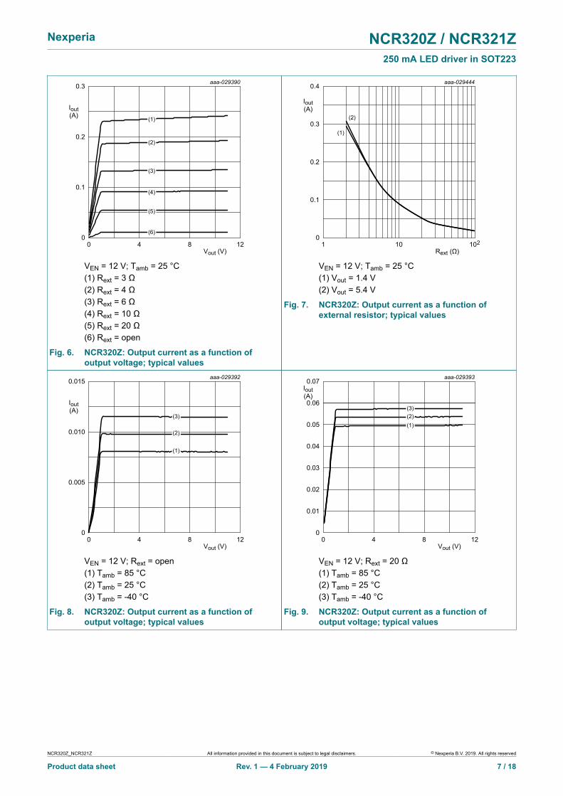
VEN = 12 V; Tamb = 25 °C(1) Rext = 3 Ω(2) Rext = 4 Ω(3) Rext = 6 Ω(4) Rext = 10 Ω(5) Rext = 20 Ω(6) Rext = open
Fig. 6. NCR320Z: Output current as a function ofoutput voltage; typical values
Rext1 10210
aaa-029444
0.2
0.1
0.3
0.4
Iout(A)
0
(1)
(2)
VEN = 12 V; Tamb = 25 °C(1) Vout = 1.4 V(2) Vout = 5.4 V
Fig. 7. NCR320Z: Output current as a function ofexternal resistor; typical values
Vout (V)0 1284
aaa-029392
0.005
0.010
0.015
Iout(A)
0
(1)
(3)
(2)
VEN = 12 V; Rext = open(1) Tamb = 85 °C(2) Tamb = 25 °C(3) Tamb = -40 °C
Fig. 8. NCR320Z: Output current as a function ofoutput voltage; typical values
Vout (V)0 1284
aaa-0293930.07
Iout(A)
0
0.01
0.02
0.03
0.04
0.05
0.06
(1)
(3)(2)
VEN = 12 V; Rext = 20 Ω(1) Tamb = 85 °C(2) Tamb = 25 °C(3) Tamb = -40 °C
Fig. 9. NCR320Z: Output current as a function ofoutput voltage; typical values
NCR320Z_NCR321Z All information provided in this document is subject to legal disclaimers. © Nexperia B.V. 2019. All rights reserved
Product data sheet Rev. 1 — 4 February 2019 7 / 18
Nexperia NCR320Z / NCR321Z250 mA LED driver in SOT223
Vout (V)0 1284
aaa-029394
0.1
0.2
0.3
Iout(A)
0
(1)
(2)(3)
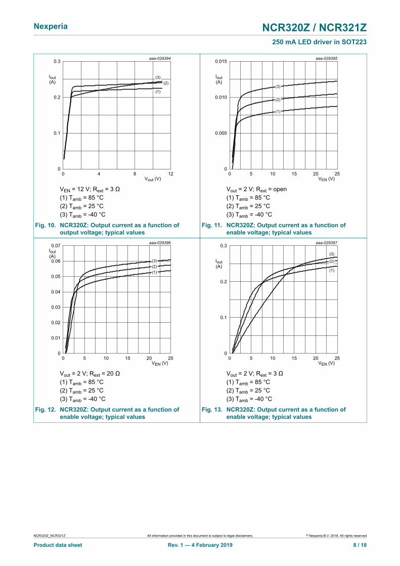
VEN = 12 V; Rext = 3 Ω(1) Tamb = 85 °C(2) Tamb = 25 °C(3) Tamb = -40 °C
Fig. 10. NCR320Z: Output current as a function ofoutput voltage; typical values
VEN (V)0 252010 155
aaa-029395
0.005
0.010
0.015
Iout(A)
0
(1)
(3)
(2)
Vout = 2 V; Rext = open(1) Tamb = 85 °C(2) Tamb = 25 °C(3) Tamb = -40 °C
Fig. 11. NCR320Z: Output current as a function ofenable voltage; typical values
aaa-029396
VEN (V)0 252010 155
0.07Iout(A)
0.05
0.03
0.01
0
0.02
0.04
0.06
(1)
(3)(2)
Vout = 2 V; Rext = 20 Ω(1) Tamb = 85 °C(2) Tamb = 25 °C(3) Tamb = -40 °C
Fig. 12. NCR320Z: Output current as a function ofenable voltage; typical values
VEN (V)0 252010 155
aaa-029397
0.1
0.2
0.3
Iout(A)
0
(1)
(3)
(2)
Vout = 2 V; Rext = 3 Ω(1) Tamb = 85 °C(2) Tamb = 25 °C(3) Tamb = -40 °C
Fig. 13. NCR320Z: Output current as a function ofenable voltage; typical values
NCR320Z_NCR321Z All information provided in this document is subject to legal disclaimers. © Nexperia B.V. 2019. All rights reserved
Product data sheet Rev. 1 — 4 February 2019 8 / 18
Nexperia NCR320Z / NCR321Z250 mA LED driver in SOT223
VEN (V)0 252010 155
aaa-029398
0.1
0.2
0.3
Iout(A)
0
(4)
(6)
(5)
(1)
(3)
(2)
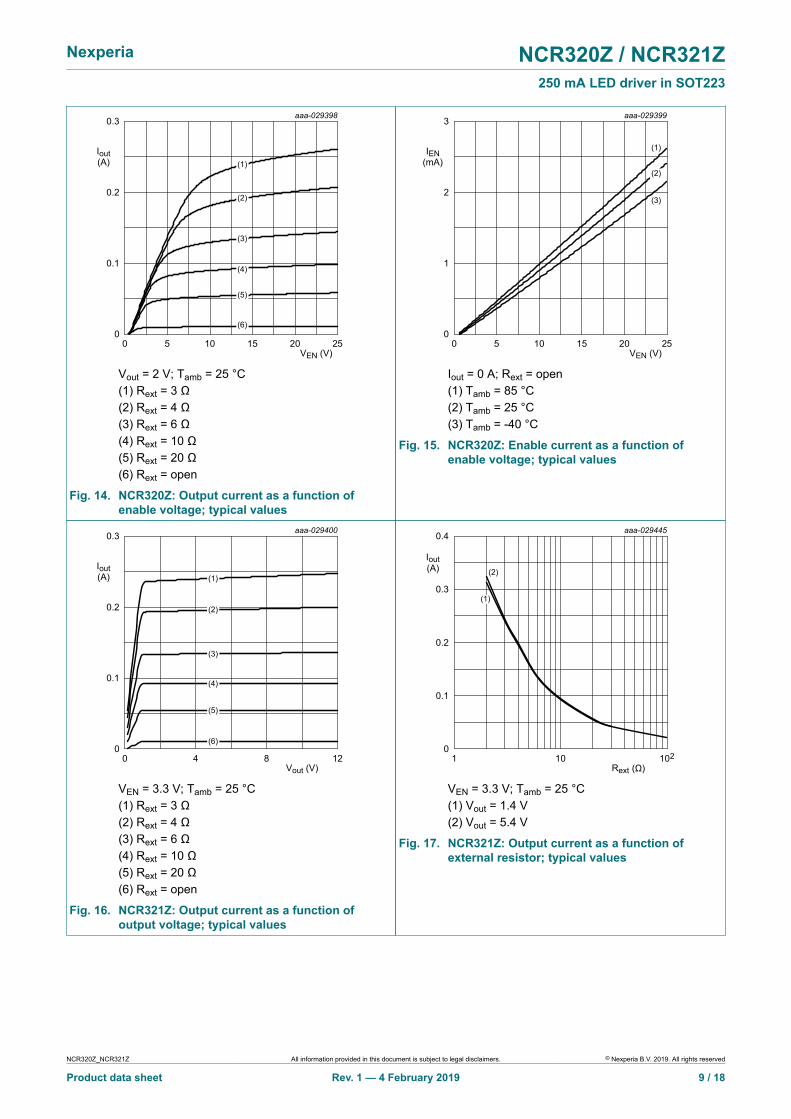
Vout = 2 V; Tamb = 25 °C(1) Rext = 3 Ω(2) Rext = 4 Ω(3) Rext = 6 Ω(4) Rext = 10 Ω(5) Rext = 20 Ω(6) Rext = open
Fig. 14. NCR320Z: Output current as a function ofenable voltage; typical values
VEN (V)0 252010 155
aaa-029399
1
2
3
IEN(mA)
0
(1)
(3)
(2)
Iout = 0 A; Rext = open(1) Tamb = 85 °C(2) Tamb = 25 °C(3) Tamb = -40 °C
Fig. 15. NCR320Z: Enable current as a function ofenable voltage; typical values
Vout (V)0 1284
aaa-029400
0.1
0.2
0.3
Iout(A)
0
(1)
(2)
(3)
(4)
(5)
(6)
VEN = 3.3 V; Tamb = 25 °C(1) Rext = 3 Ω(2) Rext = 4 Ω(3) Rext = 6 Ω(4) Rext = 10 Ω(5) Rext = 20 Ω(6) Rext = open
Fig. 16. NCR321Z: Output current as a function ofoutput voltage; typical values
Rext1 10210
aaa-029445
0.2
0.1
0.3
0.4
Iout(A)
0
(1)
(2)
VEN = 3.3 V; Tamb = 25 °C(1) Vout = 1.4 V(2) Vout = 5.4 V
Fig. 17. NCR321Z: Output current as a function ofexternal resistor; typical values
NCR320Z_NCR321Z All information provided in this document is subject to legal disclaimers. © Nexperia B.V. 2019. All rights reserved
Product data sheet Rev. 1 — 4 February 2019 9 / 18
Nexperia NCR320Z / NCR321Z250 mA LED driver in SOT223
Vout (V)0 1284
aaa-029402
0.005
0.010
0.015
Iout(A)
0
(1)
(3)
(2)
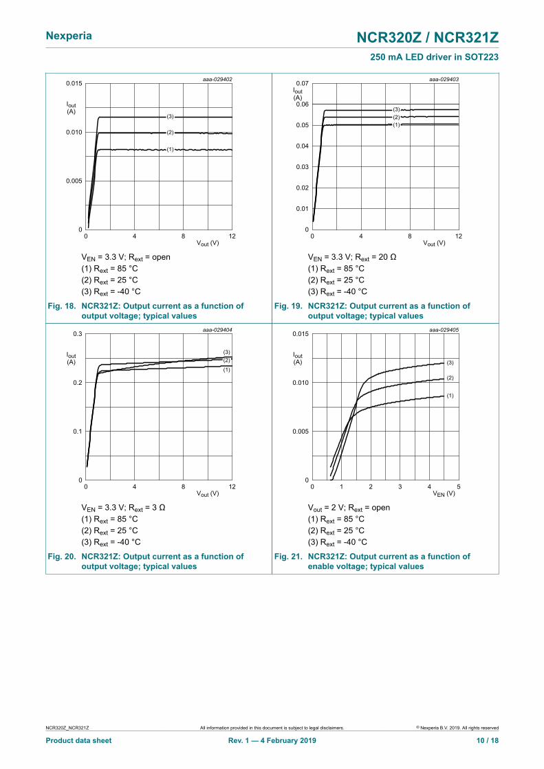
VEN = 3.3 V; Rext = open(1) Rext = 85 °C(2) Rext = 25 °C(3) Rext = -40 °C
Fig. 18. NCR321Z: Output current as a function ofoutput voltage; typical values
Vout (V)0 1284
aaa-0294030.07
Iout(A)
0
0.01
0.02
0.03
0.04
0.05
0.06
(1)
(3)(2)
VEN = 3.3 V; Rext = 20 Ω(1) Rext = 85 °C(2) Rext = 25 °C(3) Rext = -40 °C
Fig. 19. NCR321Z: Output current as a function ofoutput voltage; typical values
Vout (V)0 1284
aaa-029404
0.1
0.2
0.3
Iout(A)
0
(1)
(3)(2)
VEN = 3.3 V; Rext = 3 Ω(1) Rext = 85 °C(2) Rext = 25 °C(3) Rext = -40 °C
Fig. 20. NCR321Z: Output current as a function ofoutput voltage; typical values
VEN (V)0 542 31
aaa-029405
0.005
0.010
0.015
Iout(A)
0
(1)
(3)
(2)
Vout = 2 V; Rext = open(1) Rext = 85 °C(2) Rext = 25 °C(3) Rext = -40 °C
Fig. 21. NCR321Z: Output current as a function ofenable voltage; typical values
NCR320Z_NCR321Z All information provided in this document is subject to legal disclaimers. © Nexperia B.V. 2019. All rights reserved
Product data sheet Rev. 1 — 4 February 2019 10 / 18
Nexperia NCR320Z / NCR321Z250 mA LED driver in SOT223
aaa-029406
VEN (V)0 542 31
0.07Iout(A)
0.05
0.03
0.01
0
0.02
0.04
0.06
(1)
(3)(2)
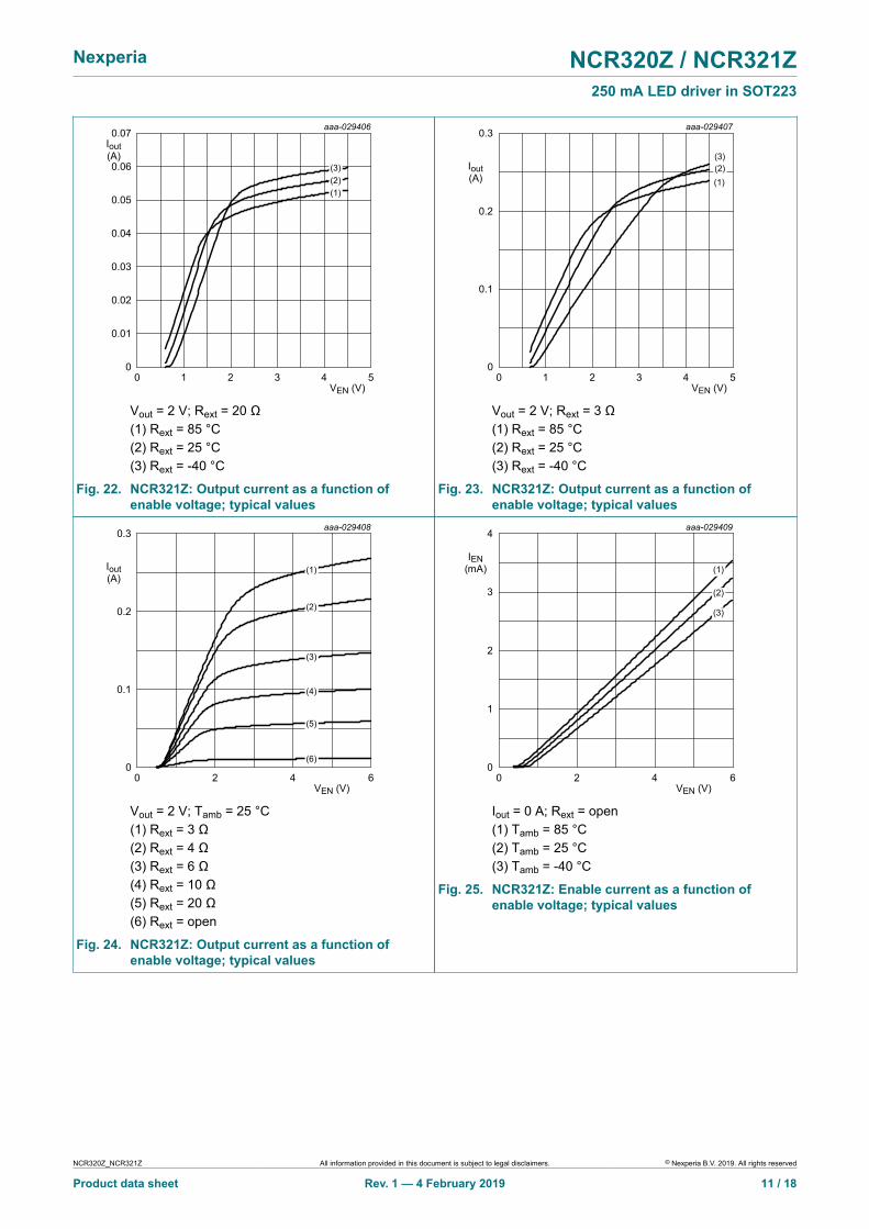
Vout = 2 V; Rext = 20 Ω(1) Rext = 85 °C(2) Rext = 25 °C(3) Rext = -40 °C
Fig. 22. NCR321Z: Output current as a function ofenable voltage; typical values
VEN (V)0 542 31
aaa-029407
0.1
0.2
0.3
Iout(A)
0
(1)
(3)(2)
Vout = 2 V; Rext = 3 Ω(1) Rext = 85 °C(2) Rext = 25 °C(3) Rext = -40 °C
Fig. 23. NCR321Z: Output current as a function ofenable voltage; typical values
VEN (V)0 642
aaa-029408
0.1
0.2
0.3
Iout(A)
0
(1)
(2)
(3)
(4)
(5)
(6)
Vout = 2 V; Tamb = 25 °C(1) Rext = 3 Ω(2) Rext = 4 Ω(3) Rext = 6 Ω(4) Rext = 10 Ω(5) Rext = 20 Ω(6) Rext = open
Fig. 24. NCR321Z: Output current as a function ofenable voltage; typical values
aaa-029409
VEN (V)0 642
2
1
3
4
IEN(mA)
0
(1)
(3)
(2)
Iout = 0 A; Rext = open(1) Tamb = 85 °C(2) Tamb = 25 °C(3) Tamb = -40 °C
Fig. 25. NCR321Z: Enable current as a function ofenable voltage; typical values
NCR320Z_NCR321Z All information provided in this document is subject to legal disclaimers. © Nexperia B.V. 2019. All rights reserved
Product data sheet Rev. 1 — 4 February 2019 11 / 18
Nexperia NCR320Z / NCR321Z250 mA LED driver in SOT223
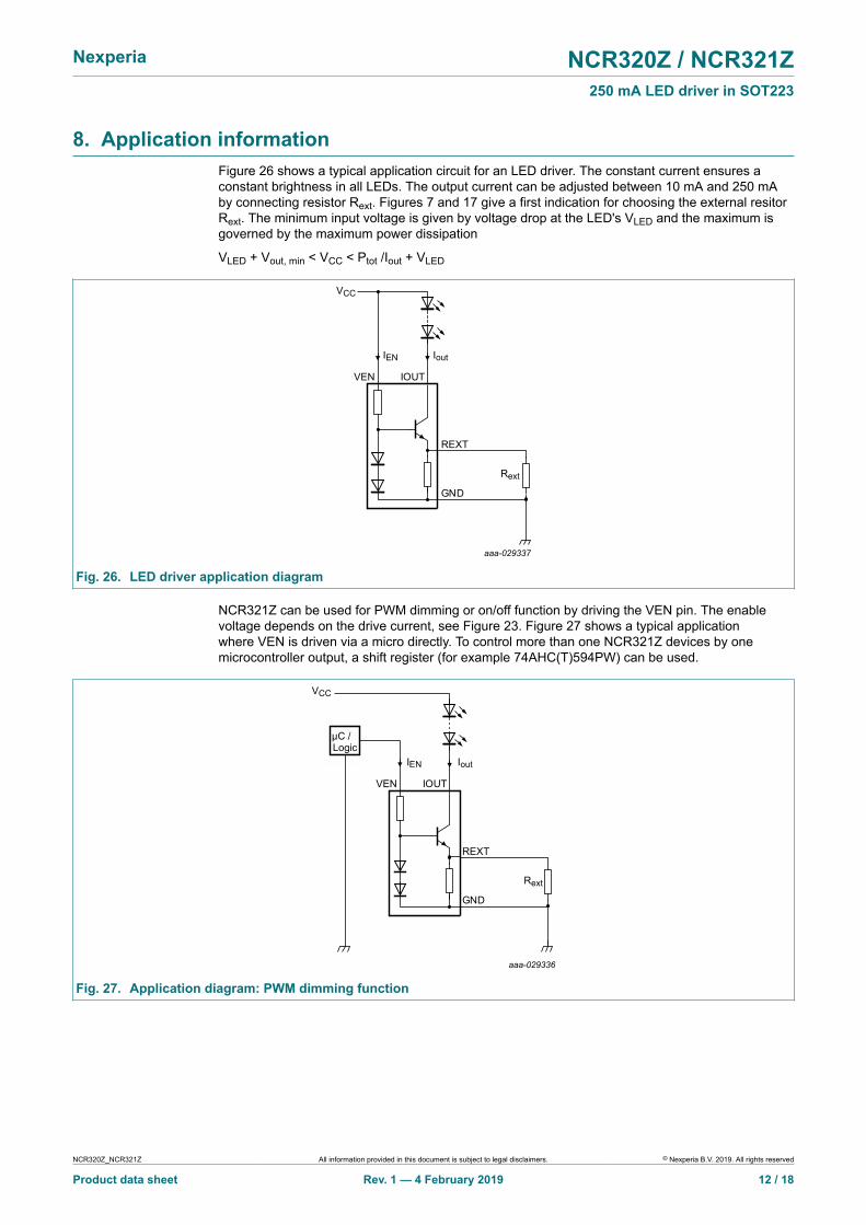
8. Application informationFigure 26 shows a typical application circuit for an LED driver. The constant current ensures aconstant brightness in all LEDs. The output current can be adjusted between 10 mA and 250 mAby connecting resistor Rext. Figures 7 and 17 give a first indication for choosing the external resitorRext. The minimum input voltage is given by voltage drop at the LED's VLED and the maximum isgoverned by the maximum power dissipation
VLED + Vout, min < VCC < Ptot /Iout + VLED
aaa-029337
VEN IOUT
REXT
GND
VCC
IoutIEN
Rext
Fig. 26. LED driver application diagram
NCR321Z can be used for PWM dimming or on/off function by driving the VEN pin. The enablevoltage depends on the drive current, see Figure 23. Figure 27 shows a typical applicationwhere VEN is driven via a micro directly. To control more than one NCR321Z devices by onemicrocontroller output, a shift register (for example 74AHC(T)594PW) can be used.
aaa-029336
VEN IOUT
REXT
GND
VCC
IoutIEN
µC /
Rext
Logic
Fig. 27. Application diagram: PWM dimming function
NCR320Z_NCR321Z All information provided in this document is subject to legal disclaimers. © Nexperia B.V. 2019. All rights reserved
Product data sheet Rev. 1 — 4 February 2019 12 / 18
Nexperia NCR320Z / NCR321Z250 mA LED driver in SOT223
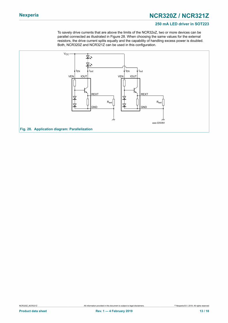
To savely drive currents that are above the limits of the NCR32xZ, two or more devices can beparallel connected as illustrated in Figure 28. When choosing the same values for the externalresistors, the drive current splits equally and the capability of handling excess power is doubled.Both, NCR320Z and NCR321Z can be used in this configuration.
VEN IOUT
REXT
GND
VCC
IoutIEN
Rext
aaa-029364
VEN IOUT
REXT
GND
IoutIEN
Rext
Fig. 28. Application diagram: Parallelization
NCR320Z_NCR321Z All information provided in this document is subject to legal disclaimers. © Nexperia B.V. 2019. All rights reserved
Product data sheet Rev. 1 — 4 February 2019 13 / 18

Nexperia NCR320Z / NCR321Z250 mA LED driver in SOT223
9. Package outline
Table 9. Package outline
UNIT A1 bp c D E e1 HE Lp Q ywv
REFERENCESOUTLINE VERSION
EUROPEAN PROJECTION ISSUE DATE
IEC JEDEC JEITA
mm 0.10 0.01
1.8 1.5
0.80 0.60
b1
3.1 2.9
0.32 0.22
6.7 6.3
3.7 3.3 2.3
e
4.6 7.3 6.7
1.1 0.7
0.95 0.85 0.1 0.10.2
DIMENSIONS (mm are the original dimensions)
SOT223 SC-73 04-11-10 06-03-16
w Mbp
D
b1
e1
e
A
A1
Lp
Q
detail X
HE
E
v M A
AB
B
c
y
0 2 4 mm
scale
A
X
1 32
4
Plastic surface-mounted package with increased heatsink; 4 leads SOT223
Fig. 29. Package outline SC-73 (SOT223)
NCR320Z_NCR321Z All information provided in this document is subject to legal disclaimers. © Nexperia B.V. 2019. All rights reserved
Product data sheet Rev. 1 — 4 February 2019 14 / 18
Nexperia NCR320Z / NCR321Z250 mA LED driver in SOT223
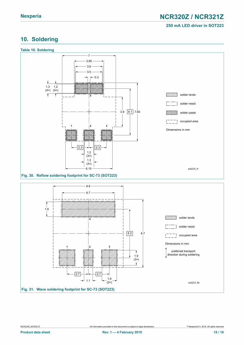
10. Soldering
Table 10. Soldering
sot223_fr
1.2 (4×)
1.2 (3×)
1.3 (4×)
1.3 (3×)
6.15
7
3.85
3.6
3.5
0.3
3.9 7.65
2.3 2.3
6.1
4
2 31
solder lands
solder resist
occupied area
solder paste
Dimensions in mm
Fig. 30. Reflow soldering footprint for SC-73 (SOT223)
sot223_fw
1.9
6.7
8.9
8.7
1.9 (3×)
1.9 (2×)1.1
6.2
2.7
2.7
2
4
31
solder lands
solder resist
occupied area
preferred transport direction during soldering
Dimensions in mm
Fig. 31. Wave soldering footprint for SC-73 (SOT223)
NCR320Z_NCR321Z All information provided in this document is subject to legal disclaimers. © Nexperia B.V. 2019. All rights reserved
Product data sheet Rev. 1 — 4 February 2019 15 / 18
Nexperia NCR320Z / NCR321Z250 mA LED driver in SOT223
11. Revision history
Table 11. Revision historyDocument ID Release date Data sheet status Change
noticeSupersedes
NCR320Z_NCR321Z v.1 20190204 Product data sheet - -
NCR320Z_NCR321Z All information provided in this document is subject to legal disclaimers. © Nexperia B.V. 2019. All rights reserved
Product data sheet Rev. 1 — 4 February 2019 16 / 18
Nexperia NCR320Z / NCR321Z250 mA LED driver in SOT223
12. Legal information
Data sheet status
Document status[1][2]
Productstatus [3]
Definition
Objective [short]data sheet
Development This document contains data fromthe objective specification forproduct development.
Preliminary [short]data sheet
Qualification This document contains data fromthe preliminary specification.
Product [short]data sheet
Production This document contains the productspecification.
[1] Please consult the most recently issued document before initiating orcompleting a design.
[2] The term 'short data sheet' is explained in section "Definitions".[3] The product status of device(s) described in this document may have
changed since this document was published and may differ in case ofmultiple devices. The latest product status information is available onthe internet at https://www.nexperia.com.
DefinitionsDraft — The document is a draft version only. The content is still underinternal review and subject to formal approval, which may result inmodifications or additions. Nexperia does not give any representations orwarranties as to the accuracy or completeness of information included hereinand shall have no liability for the consequences of use of such information.
Short data sheet — A short data sheet is an extract from a full data sheetwith the same product type number(s) and title. A short data sheet isintended for quick reference only and should not be relied upon to containdetailed and full information. For detailed and full information see the relevantfull data sheet, which is available on request via the local Nexperia salesoffice. In case of any inconsistency or conflict with the short data sheet, thefull data sheet shall prevail.
Product specification — The information and data provided in a Productdata sheet shall define the specification of the product as agreed betweenNexperia and its customer, unless Nexperia and customer have explicitlyagreed otherwise in writing. In no event however, shall an agreement bevalid in which the Nexperia product is deemed to offer functions and qualitiesbeyond those described in the Product data sheet.
DisclaimersLimited warranty and liability — Information in this document is believedto be accurate and reliable. However, Nexperia does not give anyrepresentations or warranties, expressed or implied, as to the accuracyor completeness of such information and shall have no liability for theconsequences of use of such information. Nexperia takes no responsibilityfor the content in this document if provided by an information source outsideof Nexperia.
In no event shall Nexperia be liable for any indirect, incidental, punitive,special or consequential damages (including - without limitation - lostprofits, lost savings, business interruption, costs related to the removalor replacement of any products or rework charges) whether or not suchdamages are based on tort (including negligence), warranty, breach ofcontract or any other legal theory.
Notwithstanding any damages that customer might incur for any reasonwhatsoever, Nexperia’s aggregate and cumulative liability towards customerfor the products described herein shall be limited in accordance with theTerms and conditions of commercial sale of Nexperia.
Right to make changes — Nexperia reserves the right to make changesto information published in this document, including without limitationspecifications and product descriptions, at any time and without notice. Thisdocument supersedes and replaces all information supplied prior to thepublication hereof.
Suitability for use in automotive applications — This Nexperia producthas been qualified for use in automotive applications. Unless otherwiseagreed in writing, the product is not designed, authorized or warranted tobe suitable for use in life support, life-critical or safety-critical systems or
equipment, nor in applications where failure or malfunction of an Nexperiaproduct can reasonably be expected to result in personal injury, death orsevere property or environmental damage. Nexperia and its suppliers acceptno liability for inclusion and/or use of Nexperia products in such equipment orapplications and therefore such inclusion and/or use is at the customer's ownrisk.
Quick reference data — The Quick reference data is an extract of theproduct data given in the Limiting values and Characteristics sections of thisdocument, and as such is not complete, exhaustive or legally binding.
Applications — Applications that are described herein for any of theseproducts are for illustrative purposes only. Nexperia makes no representationor warranty that such applications will be suitable for the specified usewithout further testing or modification.
Customers are responsible for the design and operation of their applicationsand products using Nexperia products, and Nexperia accepts no liability forany assistance with applications or customer product design. It is customer’ssole responsibility to determine whether the Nexperia product is suitableand fit for the customer’s applications and products planned, as well asfor the planned application and use of customer’s third party customer(s).Customers should provide appropriate design and operating safeguards tominimize the risks associated with their applications and products.
Nexperia does not accept any liability related to any default, damage, costsor problem which is based on any weakness or default in the customer’sapplications or products, or the application or use by customer’s third partycustomer(s). Customer is responsible for doing all necessary testing for thecustomer’s applications and products using Nexperia products in order toavoid a default of the applications and the products or of the application oruse by customer’s third party customer(s). Nexperia does not accept anyliability in this respect.
Limiting values — Stress above one or more limiting values (as defined inthe Absolute Maximum Ratings System of IEC 60134) will cause permanentdamage to the device. Limiting values are stress ratings only and (proper)operation of the device at these or any other conditions above thosegiven in the Recommended operating conditions section (if present) or theCharacteristics sections of this document is not warranted. Constant orrepeated exposure to limiting values will permanently and irreversibly affectthe quality and reliability of the device.
Terms and conditions of commercial sale — Nexperia products aresold subject to the general terms and conditions of commercial sale, aspublished at http://www.nexperia.com/profile/terms, unless otherwise agreedin a valid written individual agreement. In case an individual agreement isconcluded only the terms and conditions of the respective agreement shallapply. Nexperia hereby expressly objects to applying the customer’s generalterms and conditions with regard to the purchase of Nexperia products bycustomer.
No offer to sell or license — Nothing in this document may be interpretedor construed as an offer to sell products that is open for acceptance or thegrant, conveyance or implication of any license under any copyrights, patentsor other industrial or intellectual property rights.
Export control — This document as well as the item(s) described hereinmay be subject to export control regulations. Export might require a priorauthorization from competent authorities.
Translations — A non-English (translated) version of a document is forreference only. The English version shall prevail in case of any discrepancybetween the translated and English versions.
TrademarksNotice: All referenced brands, product names, service names andtrademarks are the property of their respective owners.
NCR320Z_NCR321Z All information provided in this document is subject to legal disclaimers. © Nexperia B.V. 2019. All rights reserved
Product data sheet Rev. 1 — 4 February 2019 17 / 18
Nexperia NCR320Z / NCR321Z250 mA LED driver in SOT223
Contents
1. Product profile.............................................................. 11.1. General description......................................................11.2. Features and benefits..................................................11.3. Applications................................................................. 11.4. Quick reference data................................................... 22. Pinning information......................................................23. Ordering information....................................................24. Marking.......................................................................... 25. Limiting values............................................................. 36. Thermal characteristics............................................... 47. Characteristics..............................................................68. Application information............................................. 129. Package outline.......................................................... 1410. Soldering................................................................... 1511. Revision history........................................................1612. Legal information......................................................17
© Nexperia B.V. 2019. All rights reservedFor more information, please visit: http://www.nexperia.comFor sales office addresses, please send an email to: [email protected] of release: 4 February 2019
NCR320Z_NCR321Z All information provided in this document is subject to legal disclaimers. © Nexperia B.V. 2019. All rights reserved
Product data sheet Rev. 1 — 4 February 2019 18 / 18