25-26 June, 2009 CesrTA Workshop CTA09 Electron Cloud Single-Bunch Instability Modeling using CMAD...
22
25-26 June, 2009 CesrTA Workshop CTA09 Electron Cloud Single-Bunch Instability Modeling using CMAD M. Pivi CesrTA CTA09 Workshop 25-26 June 2009
-
Upload
eustace-franklin -
Category
Documents
-
view
213 -
download
0
Transcript of 25-26 June, 2009 CesrTA Workshop CTA09 Electron Cloud Single-Bunch Instability Modeling using CMAD...
25-26 June, 2009 CesrTA Workshop CTA09
Electron Cloud Single-Bunch Instability Modeling using CMAD
M. Pivi
CesrTA CTA09 Workshop
25-26 June 2009

– Simulate a real lattice including the variation of beta functions, dispersion, chromaticity, etc.
– Parallel simulations to deal with several ring elements (> 1000) and many turns (>1000)
– Treat the electron cloud build-up (build-up is not there yet) and instability in the same code …
– Study incoherent emittance long-term growth below threshold: “real or numerical?”
Motivations for CMAD

Simulation code features
• CMAD is taking as input MAD-8 or -X “maps” and “optics” files
• Tracking the beam 6D (x,x’,y,y’,z,) in a MAD lattice with 1st and 2nd (2nd can be turned off) order transport maps
• Actually, the electron cloud density is defined at input, as a ring average
• Applying beam-cloud interactions at each ring element
• Multi-processor parallel simulations (needed!)

• Beam and e- cloud represented by macroparticles
• 3D electron cloud dynamics including magnetic fields
• 2D beam and electron cloud forces• Particle in cell PIC code• Feature: the user can define different cloud
density levels for different ring element types
Simulation code features
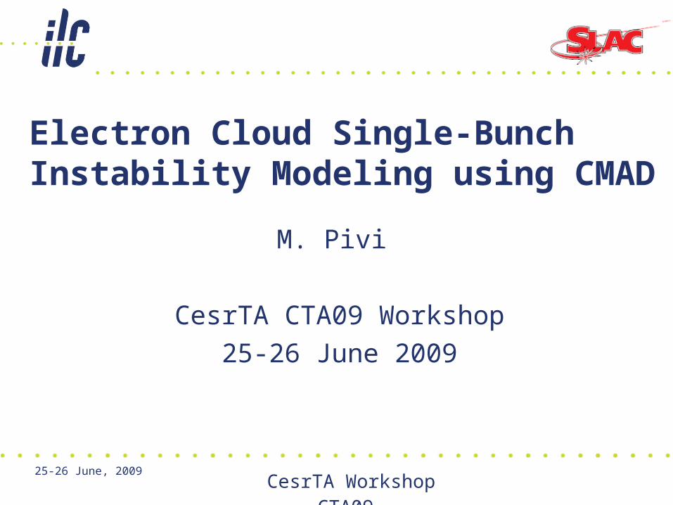
Ex: Beam Electric field
Open space: Beam Vertical electric field using 300000 macroparticles (middle of LHC beam)

Electron cloud forces: Electric field
Open space: e- Cloud Vertical Electric field using 100000 macroelectrons (middle of LHC beam)

Scalability of parallel computation
• Typically ~70-100 computer processors used• Example: gain factor 53 in speed with 70 processors
Computing time (using NERSC computers) vs number of processors; example: LHC with 100 interactions / turn

Recent codes benchmarking (1/3)
• Compare with Head-Tail (CERN) and WARP (LBNL) http://conf-ecloud02.web.cern.ch/conf-ecloud02/CodeComparison/modelinst.htm
(CERN page) • Head-Tail (G. Rumolo CERN) has been
benchmarked with other codes, ex . PEHTS (Ohmi, KEK), with good results.
1 beam-cloud IP/turn, SPS with cloud density 1e12m^3. “New 2006 simulations results”
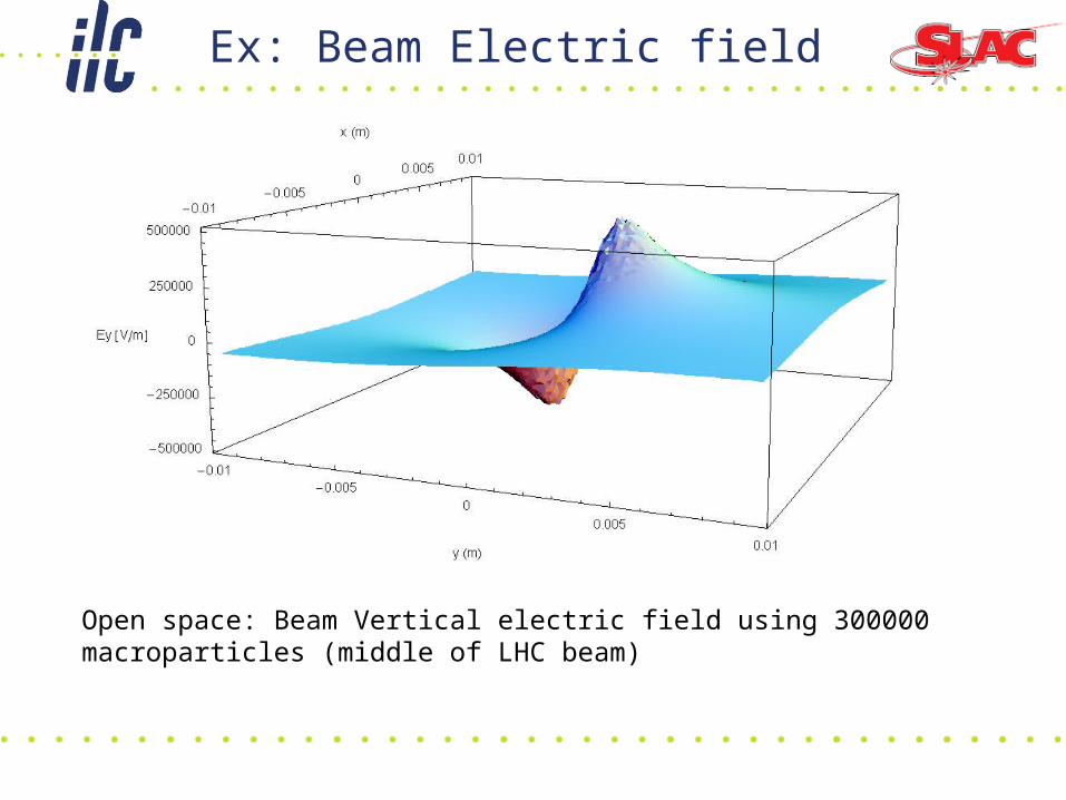
• Compared with Head-Tail (G. Rumolo, R. Thomas CERN) and WARP (J-L Vay and Kiran Sonnad LBNL) http://conf-ecloud02.web.cern.ch/conf-ecloud02/CodeComparison/modelinst.htm
(CERN page)
100 beam-cloud IP/turn. LHC with cloud density 1e12 to 1e14m^-3. 2008 simulations results. Constant beta function. Magnetic free region.
Recent codes benchmarking (2/3)

SPS/CERN lattice simplified from MADX with 250 beam-cloud interactions IP/turn.
Energy (GeV) 26
Bunch population 1.15e11
Synchrotron tune 0.00592
Emittance (m) 1e-7
z 0.24
dp 0.003887
1.63539
Qx’, Qy’ 0
Benchmarking proposed by F. Zimmermann; Simplified lattice by R. Thomas.
Recent codes benchmarking (3/3)

SPS/CERN lattice simplified from MADX with 250 beam-cloud interactions IP/turn.
[CMAD run 3.5 hours at rate 13 sec/turn on Franklin/NERSC machine with 64 processors]
Recent codes benchmarking (3/3)
Benchmarking in collaboration with Kiran Sonnad and J-L Vay
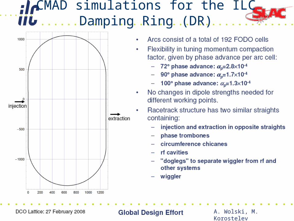
CMAD simulations for the ILC Damping Ring (DR)
A. Wolski, M. Korostelev

DR Major Parameter
A. Wolski, M. Korostelev

Magnet counts and Parameters
A. Wolski, M. Korostelev

Example: Arc Cell
CMAD includes the variation of beta functions and dispersion

ILC DR and Flat Beam
Shown the beam sizes ratio in the ILC DR. To compute the Electric fields where the beam is very flat, as in the ILC DR, is a simulation challenge; in CMAD the PIC computation is made on grids with variable sizes to adapt to very flat beams [1].– Example in case of x/y = 150:1, the transverse grid is 300x20.
[1] Y. Cai etal PRSTAB 4, 011001 (2001).

ILC DR Simulations (CMAD)
• Instability threshold as a function of different cloud densities from 1 to 8e11 e/m3
• 40% beam losses for a cloud density 8e11 e/m3
• Tracking the beam and applying beam-cloud interactions at every element except field-free regions (assume e-cloud in Drift is mitigated by solenoid)

ILC DR simulations: Synchrotron radiation camera view

ILC DR: below instability threshold
Below instability threshold: an incoherent emittance growth (seen previously by CERN and KEK simulations) still persists. Tune footprint gets large and resonances are crossed (G. Franchetti) causing emittance increase. Radiation damping and quantum excitations (to be included yet) may compensate for this effect in positron rings but not in proton rings (SPS,LHC).

CesrTA work
• For CesrTA work, we will contribute with CMAD simulations (M. P. and Kiran Sonnad) possibly benchmarking with PEHTS and/or WARP:
• Setting up input file for CesrTA using cta_2000_v8_080403.mad
• Simulation CesrTA ring (by Fall 09) – information on cloud density threshold for emittance
blow-up– Tune shifts and tune footprint– Features of instability
• In parallel with CesrTA operations (FY09-FY10)– Experimentally determine electron cloud density
threshold for single-bunch instability at CesrTA
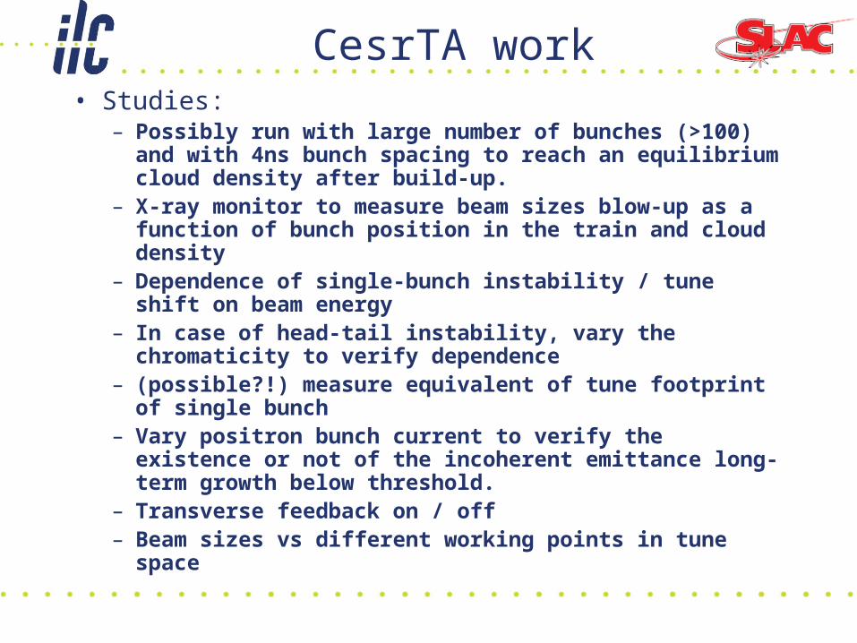
CesrTA work• Studies:
– Possibly run with large number of bunches (>100) and with 4ns bunch spacing to reach an equilibrium cloud density after build-up.
– X-ray monitor to measure beam sizes blow-up as a function of bunch position in the train and cloud density
– Dependence of single-bunch instability / tune shift on beam energy
– In case of head-tail instability, vary the chromaticity to verify dependence
– (possible?!) measure equivalent of tune footprint of single bunch
– Vary positron bunch current to verify the existence or not of the incoherent emittance long-term growth below threshold.
– Transverse feedback on / off– Beam sizes vs different working points in tune space

Summary
Code Benchmarkingof single-bunch instability codes is from good to excellent
Simulation resultsInstability threshold for ILC DR new 90deg lattice is at cloud density about ~4-8e11 m-3
More simulation confirmation of the incoherent emittance growth below threshold– (Need to include radiation damping and quantum
excitations)
NextCesrTA simulations and data benchmarkingILC DR simulations for the different momentum compaction configurations