2003 IMWA GU P &T Owners Manual - Ural Sidecar Africasidecarafrica.co.za/Gear Up Manual.pdf ·...
99
Irbit Motorcycle Factory Irbit Motorworks of America Owners Manual 2003 Model Gear Up, Patrol, Tourist www .imz-ural.com
Transcript of 2003 IMWA GU P &T Owners Manual - Ural Sidecar Africasidecarafrica.co.za/Gear Up Manual.pdf ·...

Irbit Motorcycle FactoryIrbit Motorworks of America
Owners Manual
2003 ModelGear Up, Patrol, Tourist
www.imz-ural.com

2

3
ContentsIntroduction...............................................................................................................................................................7
Warnings, Cautions, Notes.........................................................................................................................................9
Chapter 1 SpecificationsSpecifications ......................................................................................................................................................... 11Torque Specifications ............................................................................................................................................. 15
Chapter 2 Motorcycle Controls and InstrumentsMotorcycle Controls & Instrumentation .................................................................................................................. 17Controls ................................................................................................................................................................ 17Control and Instrument maintenance ....................................................................................................................... 25
Chapter 3 Engine OperationEngine Operation and Maintenance ........................................................................................................................ 27Pre-Trip Preliminaries ............................................................................................................................................ 27Starting the Engine ................................................................................................................................................. 27Operating Precautions ............................................................................................................................................ 31Running-In the New Motorcycle ............................................................................................................................ 32
Chapter 4 Engine DesignBrief Description of Design .................................................................................................................................. 33Lubrication System ................................................................................................................................................ 34Fuel System ........................................................................................................................................................... 35Ignition System ...................................................................................................................................................... 37
Chapter 5 CarburetorsCarburetors ........................................................................................................................................................... 39
Carburetor Maintenance ........................................................................................................................................ 40
Chapter 6 Power TransmissionPower Transmission ............................................................................................................................................... 41Clutch ................................................................................................................................................................... 41Gearbox ................................................................................................................................................................ 41Final Drive ............................................................................................................................................................. 42

4
Chapter 7 Running GearRunning Gear ......................................................................................................................................................... 43Motorcycle and Sidecar Frames ............................................................................................................................ 43Spring-Loaded Hydraulic Shock Absorber ............................................................................................................. 44Adjustment of Sidecar Installation ........................................................................................................................ ..45Front Fork ............................................................................................................................................................ 46Steering Head Bearings............................................................................................................................................48
Chapter 8 Wheel & TiresWheels and Tires ................................................................................................................................................... 49Tire Data ................................................................................................................................................................50Running Gear Maintenance .................................................................................................................................... 51
Chapter 9 BrakesBrakes .................................................................................................................................................................. 53Brake Adjustment .................................................................................................................................................. 53
Chapter 11 ElectricalElectrical Equipment .............................................................................................................................................. 57Electrical Circuits.....................................................................................................................................................59Electrical Equipment Maintenance .......................................................................................................................... 59Wiring Diagram...................................................................................................................................................... 60
Chapter 12 MaintenanceMaintenance of Motorcycle ................................................................................................................................... 61List of Recommended Lubricants ........................................................................................................................... 61Lubrication Chart ................................................................................................................................................... 63Required Lubrication ............................................................................................................................................. 64Care of Motorcycle Paint ....................................................................................................................................... 64Preservation and Storage ....................................................................................................................................... 65Battery .................................................................................................................................................................. 65List of Individual Tool Set, Spare Parts, Accessories & Documents ......................................................................... 66
Chapter 13 Gear-Up & Patrol Motorcycle With Engageable Sidecar DrivePatrol Motorcycle with Engageable Sidecar Drive ................................................................................................. 69Description ............................................................................................................................................................ 69Handling Differences from the Single Wheel Drive .................................................................................................. 69Sidecar Maintenance ............................................................................................................................................. 70
Chapter 14 Learning to Ride the URALLearning to Ride the Ural Motorcycle with Sidecar Accessory ................................................................................ 71Safe Operating Rules ............................................................................................................................................. 73

5
Chapter 15 WarrantyWarranty ............................................................................................................................................................... 75Warranty Claim Form ........................................................................................................................................... 81Flat Rate Schedule ............................................................................................................................................... 82
Chapter 16 Service CouponsService Coupons ................................................................................................................................................... 85New Address Form ............................................................................................................................................... 95New Owner Form ................................................................................................................................................. 96URAL Starting and Running Tips ............................................................................................................................ 97

6

7
INTRODUCTIONWelcome to the URAL Motorcycling Family! Your Ural has been built by the Irbit Motorcycle Factory inRussia and distributed by Irbit Motorworks of America, the United States affiliate of the Irbit MotorcycleFactory. The Ural motorcycle conforms to all applicable US Federal Motor Vehicle Safety Standards andUS Environmental Protection Agency regulations effective on the date of manufacture. This manualcovers the Gear-Up, Patrol, and Tourist models.
This manual has been prepared to acquaint you with the operation, care and maintenance of yourmotorcycle, and to provide you with important safety information. Follow these instructions carefully formaximum motorcycle performance and for your personal motorcycling safety and pleasure. Please payparticular attention to the section “Learning to Ride the Ural Motorcycle with Sidecar”. It is critical that abeginning sidecar driver becomes thoroughly familiar with the special operating characteristics ofsidecar outfits before venturing out on the busy roads.
Your Owner’s Manual contains instructions for operation, maintenance and minor repairs. Major repairsrequire the attention of a skilled mechanic and the use of special tools and equipment. Your AuthorizedIMWA Ural Dealer has the facilities, experience and genuine Ural parts necessary to properly render thisvaluable service.
Any suggestions or comments are welcome! Write to us or post an e-mail on the Ural Discussionbulletin board at www.imz-ural.com.
Happy Riding!

8

9
Important Notice!Statements in this manual preceded by the following words are of special importance:
WARNING: MEANS THERE IS THE POSSIBILITY OF PERSONAL INJURY TOYOURSELF OR OTHERS.
CAUTION: Means there is the possibility of damage to the vehicle.
NOTE: Other information of particular importance has been placed initalic type.
CAUTION! During the initial 1,500 km, a fundamental bedding-in of parts for all themechanisms of the motorcycle takes place. During this period do not race, overload, or lug theengine.Note the riding procedures described in the section “Running-In of New Motorcycle.”Following those procedures will ensure that you have the most powerful & smoothly operatingengine after break-in.
Maintenance intervals recommended are based on operational experience under various climatic androad conditions. However, these intervals may be modified following repeated checks of the lubricantcondition and general mechanical condition of the motorcycle.
Carefully study this Owner’s Manual before starting the motorcycle.
Specifications and design are subject to change without notice.

10

11
Chapter 1SPECIFICATIONS GENERAL
Patrol & Gear-Up Tourist
Maximum speed of motorcycle 95 km/h 59 mph 105 km/h 65 mph Dry mass of motorcycle 736 lb 736 lb. Maximum Gross Vehicle Weight 1344lb. 1344 lb. Noise level below 80db below 80db Fuel consumption 31.3 mpg 31.3mpg
OVERALL DIMENSIONS
Length 2580 mm / 8 ft Width 1700 mm / 5 ft 6 in Height 1100 mm / 3 ft 6 in Road Clearance 125 mm / 5 in Seat height 840 mm / 33 in Wheel base 1470 mm / 58 in
ENGINE
Type 4 stroke, overhead valves, opposed twin-cylinder Displacement 745 cc Cylinder bore 78 mm Piston stroke 78 mm Compression ratio 8.6 :1 Rated horsepower 23 KW / 45 BHp Rated rotational speed 5600 RPM Rated torque 52 N -M @ 3750 RPM Lubrication system Dual system of forced lubrication and splashing Lubricant SAE 20W/50
CARBURETOR
Carburetor type 32 CVK Keihin Number of carburetors 2 Air cleaner Paper Filter Element Fuel 91 octane premium unleaded gasoline PCV Valve Internal Breather

12
ELECTRICAL
Ignition system Electronic IgnitionSpark plugs NGK BP7HS or EquivalentIgnition timing Automatic advanceAlternator 35 amp / 12 VoltBattery VARTA YB18L-A or equivalentHeadlight Hela, 7" round sealed beam
TRANSMISSIONClutch Dry double-disk clutchGearbox 4 speed gearbox with reverse
GEAR RATIOSI gear 3.6II gear 2.28III gear 1.56IV gear 1.19Reverse gear 4.36
Speedometer drive ratio 0.4Final drive ratio 4.62
FLUID CAPACITIESPatrol, Gear Up Tourist
Fuel tank (gasoline) 5 Gal / 19L 5 Gal / 19LReserve (gasoline) .5 Gal / 2L .5 Gal / 2LEngine (oil) 68 Oz / 2L 68 Oz / 2LTransmission (oil) 34 Oz / 1 L 34 Oz / 1 LFinal drive (gear oil) 4.5 Oz / 135 ml 3.5 Oz / 105 mlShock Absorbers (shock oil) 3.5 Oz / 105 ml 3.5 Oz / 105 mlBrake Reservoir DOT 3 or 4 brake fluid to upper line

13
RUNNING GEAR
Frame Tubular welded
Rear wheel suspension Swing arms withspring shock absorbers
Front fork Leading link
Sidecar Cushioned body (on rubbercushions) and wheel withhydraulic spring shock absorber
Sidecar drive Steel shaft driven by final drive. User selectable for engage(Patrol and Gear Up only) ment.
Brakes Disc-type with hydraulic drive on front, Shoe type withmechanical drive on rear and sidecar wheels
Tires 4” x 19”Front 22 psi cold (1.5 Bar / 150 kPa) Front 22 psi coldSide 22 psi cold (1.5 Bar / 150 kPa) Side 22 psi coldRear 36 psi cold (2.5 Bar / 250 kPa) Rear 36 psi cold
CLEARANCESmm in
Valves with engine cold 0.05 to 0.1 0.002 to 0.004 Between spark plug electrodes 1.016 0.040 Backlash between tooth faces of bevel gears in final drive 0.1 - 0.3 0.004
FREE TRAVEL / ADJUSTMENTSmm in
Hand brake control lever 5 - 8 0.2 - 0.3 Clutch control lever 5 - 8 0.2 - 0.3 Foot brake drive pedal ¼ of full stroke of pedal,
25 - 30 1.0 - 1.2 Toe-in distance 10 mm 3/8 inch Lean-out 1° away from sidecar

14
This page left intentionally blank

15
TORQUE SPECIFICATIONS
Metric US Equivalent Location on Bike 54 to 61 Nm 40 ft/lb to 45 ft/lb cylinder heads237 to 251 Nm 175 ft/lb to 185 ft/lb fly wheel tightening screws 19 to 30 Nm top 14 ft/lb to 22 ft/lb shock absorber 38 to 49 Nm bottom 28 ft/lb to 36 ft/lb shock absorber 30 to 35 Nm 22 ft/lb to 26 ft/lb bearing nut 30 to 35 Nm 22 ft/lb to 26 ft/lb final drive to swing arm bolts 16 to 19 Nm 12 ft/lb to 14 ft/lb oil pump bolt 6.7 to 11 Nm 5 ft/lb to 8 ft/lb engine sump 14 to 19 Nm 10 ft/lb to 14 ft/lb final drive case nuts 25 to 30 Nm 18 ft/lb to 22 ft/lb nut fastening the pinion bearing
(Patrol, Gear Up rear axle only) 68 to 90 Nm 50 ft/lb to 66 ft/lb nut fastening the pinion bearing 22 to 27 Nm 16 ft/lb to 20 ft/lb reverse gear lever nut 19 to 22 Nm 14 ft/lb to 16 ft/lb alternator gear nut136 to 163 Nm 100 ft/lb to 120 ft/lb steering stem nut

16
This page left intentionally blank

17
Chapter 2MOTORCYCLE CONTROLS & INSTRUMENTATION
Figure 1. Controls and Instrumentation
1 - Speedometer 12 - Gear shift (foot) pedal 2 - Turn indicator lamp 13 - Turn signal switch 3 - Trip odometer reset knob 14 - Horn push-button 4 - Neutral and reverse gear engagement 15 - “High-low” beam switch indicator lamp 16 - Clutch control lever 5 - Front brake control lever 17 - Steering damper tightening bolt 6 - Throttle control twist grip 18 - High-beam indicator lamp 7 - Ignition cutoff switch 19 - Ignition Switch 8 - Electric Start Button 20 - Battery discharge warning lamp 9 - Rear brake pedal & sidecar wheel brake 21 - Parking brake10 - Reverse gear lever11 - Kick start lever

18
Clutch Control Lever Font Brake Control Lever
Clutch control lever . When the clutch lever is squeezed, the engine is disengaged from thegearbox. When the lever is released, the engine and gearbox are engaged.
WARNING: MAKE SURE FINGERS ARE NOT POSITIONED BETWEEN HAND CONTROL LEVERS AND HANDLEBARGRIPS OR OPERATION OF VEHICLE COULD BE IMPAIRED.
WARNING: BEFORE STARTING ENGINE, ALWAYS SHIFT TRANSMISSION TO NEUTRAL TO PREVENT ACCIDENTALMOVEMENT WHICH COULD CAUSE POSSIBLE DAMAGE TO MOTORCYCLE AND PERSONAL INJURY.
Caution: Always engage the clutch release lever when shifting. Serious internal damage mayresult to the transmission if the clutch release lever is not engaged.
Front brake control lever When the lever is squeezed, the front wheel brake is actuated. Thefront brake should be used together with rear brake.
When the brake lever is squeezed, the stop signal lights are switched on.
19
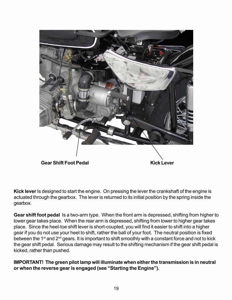
Kick lever Is designed to start the engine. On pressing the lever the crankshaft of the engine isactuated through the gearbox. The lever is returned to its initial position by the spring inside thegearbox.
Gear shift foot pedal Is a two-arm type. When the front arm is depressed, shifting from higher tolower gear takes place. When the rear arm is depressed, shifting from lower to higher gear takesplace. Since the heel-toe shift lever is short-coupled, you will find it easier to shift into a highergear if you do not use your heel to shift, rather the ball of your foot. The neutral position is fixedbetween the 1st and 2nd gears. It is important to shift smoothly with a constant force and not to kickthe gear shift pedal. Serious damage may result to the shifting mechanism if the gear shift pedal iskicked, rather than pushed.
IMPORTANT! The green pilot lamp will illuminate when either the transmission is in neutralor when the reverse gear is engaged (see “Starting the Engine”).
Gear Shift Foot Pedal Kick Lever

20
Parking Brake Sidecar Drive Lever Reverse Gear Lever Rear Brake Pedal
Parking Brake is used to hold the bike when parked. To engage, depress the rear brake pedaland push down then twist the parking brake lever counter clockwise.
Sidecar drive engagement lever is used to engage the drive axle to the sidecar wheel on thePatrol and Gear Up model motorcycles.
WARNING: Never engage sidecar drive on concrete or hard surface. Severe damage todrivetrain will result if the sidecar drive is engaged on pavement.
Reverse gear lever is used to move the motorcycle in reverse. The transmission must be inneutral or 1st gear for reverse gear to be engaged.
Rear brake lever is used to actuate the rear brakes.WARNING: DO NOT APPLY EITHER BRAKE STRONGLY ENOUGH TO LOCK THE WHEELS BECAUSE THIS MAYCAUSE POSSIBLE LOSS OF CONTROL OF THE MOTORCYCLE. ALWAYS USE BOTH BRAKES. NEVER STOP WITHFRONT OR REAR BRAKE ONLY.
WARNING: AN IMPROPERLY ADJUSTED REAR BRAKE PEDAL COULD INTERFERE WITH PROPER REAR BRAKEOPERATION RESULTING IN POOR BRAKE ACTION.

21
Off All electrical systems are off.Run Voltage is supplied to all electrical systems.Parking Voltage is supplied to running lights only.
Note: Leaving the key in the Run or Parking position will discharge the battery.Always return the key to the Off position before removing it.
Ignition Switch has three fixed positions of thekey. The position and switching diagram of theignition locks are shown above.

22
The indicator lamps are mounted on the instrument board:
Alternator failure Turn indicatorindicator lamp pilot lamp
Head lamp high Gearbox neutralbeam indicator indicator lamplamp
Turn indicator pilot lamp indicates that the turn signals are activated.
Alternator fault indicator lamp, indicates that the charging system is malfunctioning and needsimmediate attention.
Gearbox neutral and reverse gear engagement, indicates that the gearbox is either in neutralor in reverse.
Head lamp high beam indicator, indicates that the headlight high beam is activated.
Speedometer is on the dash board, with trip and total odometer. The trip odometer is reset tozero by rotating knob (Fig.1, # 3) counterclockwise. Note that the odometer reads in kilometersnot miles.

23
Electric Start Button Ignition Cutoff Switch
Low and High Beam Light Switch Turn Indicator Switch Horn Push Button

24
Throttle Control is on the right handlebar. Turning the twist grip increases engine speed.
Ignition Cutoff Switch has two positions, ignition off (up), and ignition on (down).Electric Start Button is located on the right-hand twist grip, below the kill switch.
Low and High Beam Light Switch has two positions, high beam (up), and low beam (down).Turn indicator switch is used for signaling a turnHorn push-button is used to activate the horn
Steering Damper absorbs lateral kicks to the front wheel. Turning tightening bolt (clockwise in-creases friction. This can be used while riding over bad roads.
STEERING DAMPER ADJUSTMENT KNOB
WARNING: DO NOT TIGHTEN THE DAMPER TO THE POINT WHERE THE STEERING BECOMES STIFF. DOING SOWILL ADVERSELY AFFECT HANDLING QUALITIES AND MAY DAMAGE THE STEERING MECHANISM.
Parking brake is located on the right side of the motorcycle next to the foot peg. It is engaged byapplying the foot brake pedal fully and turning the handle and pushing it down to hold the foot brakelever in the applied position.
Always disengage the parking brake before moving the motorcycle.

25
CONTROL CABLE ADJUSTMENT
The control cables are adjusted by screw adjustments at the cable ends.
With the control levers released:• for the clutch a play at the clutch lever end should be equal to 5 - 8 mm/0.2 - 0.3 in.• The rear brake pedal equal to about 25 - 30 mm/1- 1.2 in. of the full stroke of the pedal is required• for the carburetors - carburetor throttle cables synchronized
With the control levers (handles) fully depressed:• for the clutch — complete disengagement of the engine from the transmission; noiseless shifting of gears means correct adjustment of the clutch cable.• for the carburetors — lift of throttles to maximum and equal height
CONTROL CABLE MAINTENANCE
The daily preventative maintenance involves checking the functioning, condition and fastening ofthe tie rods, cables and braking action. Refer to the Service Coupons for lubrication schedule.
As per the service coupons;• check the condition of the brakes• clean the brake shoes and the active surface of the brake drums• lubricate the hinge pins and the cams of the brake linings, the joints, the linkage of the rear and
sidecar wheel brakes, the lever axle, the parking brake, the throttle control twist grip, the leverpins and ends of cables used in the clutch, the front brake control, the control cables used inthe clutch, the front brake and the throttles.

26
SPEEDOMETER MAINTENANCE
After every 10,000 km, remove the speedometer from the motorcycle and add five or six drops ofoil into the speedometer where the cable inserts into the speedometer. This will lubricate the speed-ometer internally.
To lubricate the speedometer cable, remove the cable from the speedometer and extend it in astraight line. Apply speedometer lubricating oil or light machine oil at one end and allow it to seepthrough the length of the cable.
27
Chapter 3ENGINE OPERATION
PRE-TRIP PRELIMINARIES
Pre-Trip Check List
1. Check all lights and the horn for proper operation.2. Check the brake and clutch levers and/or pedals.3. Make sure all wheels and the final drive assemblies are securely fastened .4. Check the carburetor flanges and air filter ducts for integrity and proper alignment.5. Check the tire tread depth - should be greater than 1/8 inch.6. Check the sidecar attachment mounts – all mounts should be securely tightened.
Gasoline level in the fully filled tank should be 10 - 15 mm / ½ - ¾ in. below the lower edge of thetank filler. Do not overfill the tank.
See that the oil level in the engine crankcase is not higher than the top and not lower than thebottom marks on the dipstick with the filler plug undone.(See chapter 4 Lubrication System)
CAUTION: When checking the engine oil level, be careful that dirt and debris do notcontaminate the oil.
STARTING THE ENGINE
WARNING: BEFORE STARTING THE ENGINE, MAKE SURE THAT THE GEAR SHIFT MECHANISM IS IN THENEUTRAL POSITION (BETWEEN 1ST AND 2ND GEARS) TO PREVENT ACCIDENTAL MOVEMENT WHICH COULDCAUSE POSSIBLE DAMAGE TO MOTORCYCLE AND PERSONAL INJURY. ( FOR MORE THAN JUST STARTING, I.E.IDLING, IT IS ADVISABLE TO USE NEUTRAL GEAR.)
When the ignition is switched on, the green & red lamps on the instrument board should illumi-nate. Make sure that the reverse gear engagement (lever) is set to the front position. This isimportant since the green lamp will also be illuminated if the motorcycle is in reverse gear.Moving the reverse gear lever forward will put the gearbox in neutral.
28
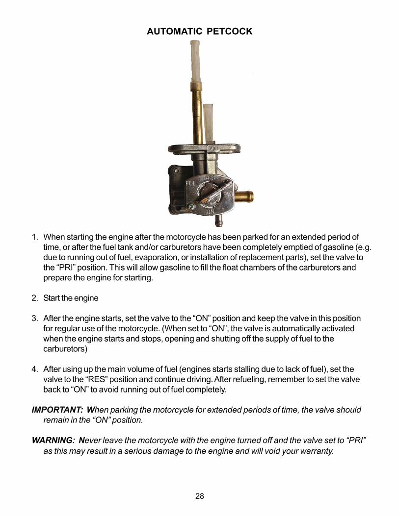
1. When starting the engine after the motorcycle has been parked for an extended period oftime, or after the fuel tank and/or carburetors have been completely emptied of gasoline (e.g.due to running out of fuel, evaporation, or installation of replacement parts), set the valve tothe “PRI” position. This will allow gasoline to fill the float chambers of the carburetors andprepare the engine for starting.
2. Start the engine
3. After the engine starts, set the valve to the “ON” position and keep the valve in this positionfor regular use of the motorcycle. (When set to “ON”, the valve is automatically activatedwhen the engine starts and stops, opening and shutting off the supply of fuel to thecarburetors)
4. After using up the main volume of fuel (engines starts stalling due to lack of fuel), set thevalve to the “RES” position and continue driving. After refueling, remember to set the valveback to “ON” to avoid running out of fuel completely.
IMPORTANT: When parking the motorcycle for extended periods of time, the valve shouldremain in the “ON” position.
WARNING: Never leave the motorcycle with the engine turned off and the valve set to “PRI”as this may result in a serious damage to the engine and will void your warranty.
AUTOMATIC PETCOCK

29
Enrichener off Enrichener on
The carburetor enricheners provide extra fuel to the mixture. This extra fuel will allow a coldengine to start and run until it has warmed up sufficiently to allow normal operation. Use cautionwhen using the enricheners, as they can easily cause the engine to flood, or foul the spark plugs.The enricheners should only be left on as long as necessary to keep the engine running whilecold and should be turned off as soon as possible.

30
Depending on the engine and ambient temperature, use the carburetor enricheners and startingprocedure as follows:
Manual Starting (without electric starter)1. Turn on the ignition and depress the kick lever (see Fig. 1) about1/4 of its travel (enough to firmly get the ball of your foot on the lever) with either your leftfoot or right foot, depending on what position is most comfortable with your right hand on thethrottle. Take up the slack in the throttle until you can feel some slight resistance from thereturn springs in the carburetors, without any advance on the throttle, since this may floodthe engine.2. Give the kick lever a swift kick. When the engine starts, blip the throttle (quickly increaseand decrease it) to keep the engine running, but not too fast. If the engine doesn’t start,repeat the kicking procedure. A properly adjusted warm engine should start within a fewkicks. If the engine doesn’t start, try the procedure described below in item3. If it still doesn’t start or fire, it may be flooded.
Note: Do not completely open the throttle while kicking the engine over since it may flood theengine and the spark plugs may become fouled with gasoline.
Electric Starting1. Set carburetor enricheners as with kick starting. Unlike manual starting, however, thegearbox does not have to be in neutral as the electric starter may be engaged with the clutchlever pulled in, or with the gearbox in neutral. Make sure the Ignition Cutoff Switch is set to “Ignition On” and push the starter button to turn over the engine.
2. When the engine has been standing for several hours but the ambient temperature ishigh (60°F/15°C degrees or above), try starting it without any enricheners. If it doesn’t fire,then use the procedure described below.
3. When the engine is cool or cold and the ambient temperature is between40°F-60°F/5°C-15°C, depress both enricheners to start. As soon as the engine starts, immediately retractthe enricheners. Run the engine at moderate speed for 30-60 seconds. If it starts to die,blip the twist grip throttle (rapidly twist part way towards full throttle and then back off) to keepthe engine running. After 1 to 3 minutes, depending on ambient temperature, the engineshould run smoothly without “blipping” the throttle.
4. If the engine is cold and ambient temperature is below 40°F, first, give the engine 5-10(depending on how cold it is) priming kicks with the ignition off. This will get some oil circu-lated to key internal parts. Engage the enricheners on both carburetors. The engine shouldthen fire, depending on how cold it is. For example, when the ambient temperature is 0°F, it

31
Note: It is very important to back off on the enricheners as soon as the engine will sustainitself without stalling. Since the Ural is a carbureted air cooled engine, the plugs will foul quickly(as soon as one minute) if the engine mixture is too rich. If one plug fouls and the other doesn’t,the engine will run unevenly and may cause internal damage.
When the engine is hot, do not choke or enrichen the carburetors. To do so risks flooding theengine.
To start an engine that is flooded, first open the throttle fully, hold it there and give the engine upto 10 swift kicks. If it still doesn’t fire, take the spark plugs out to see if they are wet with gaso-line. If they are wet, dry them. Clear excess gasoline from the cylinders by kicking the engineover 10 times with the plugs out and the throttle closed. Then replace the plugs and repeat thestarting procedure described at the beginning of this section (1).
WARNING: SUSTAINED OPERATION ON ONLY ONE CYLINDER FOR EVEN JUST A FEW MINUTES COULD OVER-HEAT THE CYLINDER AND CAUSE IRREVERSIBLE DAMAGE TO EITHER THE VALVES OR PISTON. THUS IT IS CRITI-CAL TO IMMEDIATELY SHUT THE ENGINE DOWN IF IT APPEARS TO BE RUNNING ON ONLY ONE CYLINDER.
Additional Warnings: Once the engine starts, do not allow it to run at a high speed as this couldcause abnormal wear of the parts and may lead to seizure of the piston pin and pistons in thecylinders since cold oil flows through the oil ducts with difficulty and fails to ensure sufficient lubri-cation.A correctly adjusted warm engine should run steadily at low speed with the throttle control twist gripfully closed.Do not let the motorcycle sit at idle for more than three minutes, as overheating could result.
OPERATING PRECAUTIONS
WARNING: MAKE SURE THAT SIDECAR WINDSHIELD IS IN THE FULL BACK POSITION SO IT DOESN’T INTER-FERE WITH THE RIGHT HANDLEBAR.
To move the motorcycle from rest, shift to 1st gear only. Avoid releasing the clutch suddenly, be-cause the engine is liable to stall or the motorcycle will start with a jerk. Do not drive the motor-cycle at speeds below the recommended speeds with the 2nd, 3rd or 4th gears engaged. It is notadvisable to use the 1st and 2nd gears for a long time, unless so required by road conditions.
typically takes about 5-10 rotations to start the engine. As soon as the engine starts, retractboth enricheners (after a few seconds).

32
WARNING: SHIFTING TO LOWER GEARS WHEN SPEED IS TOO HIGH MAY SEVERELY DAMAGE THETRANSMISSION OR CAUSE THE REAR WHEEL TO LOSE TRACTION.
CAUTION: Do not run the engine at extremely high rpms with clutch disengaged ortransmission in neutral. Do not idle the engine unnecessarily for more than a few minuteswith the motorcycle standing still.
When operating the Ural motorcycle on the highway, please try not to run continuously at speedsabove 65mph. If it is necessary to drive at speeds of 65mph and above, let the engine cool byrunning at a reduced speed for 10 - 15 minutes every 30 minutes if possible. This will providelonger engine life.
WARNING: WHEN RIDING ON WET ROADS OR UNDER RAINY CONDITIONS, BRAKING EFFICIENCY IS GREATLYREDUCED AND CAUTION SHOULD BE USED WHEN APPLYING THE BRAKES, ACCELERATING OR TURNING. THIS ISESPECIALLY TRUE IMMEDIATELY AFTER THE RAIN BEGINS AND THE OIL FROM THE ROAD SURFACE COMBINESWITH THE WATER.
When descending a long, steep grade, downshift and use engine compression together withintermittent application of both brakes to slow the motorcycle. Avoid continuous use of brakes toreduce overheating of the brakes and reduced efficiency.
While using the motorcycle in summer, pay special attention to the condition of the tires. Keepthem inflated up to pressures specified in this manual.
RUNNING IN THE NEW MOTORCYCLE
The running-in period for the motorcycle is the first 1,500 km.
There are no special procedures that must be followed, but during the running-in period, a newmotorcycle requires the most careful attention. In the course of this period, do not overload themachine. Avoid traveling on freeways and climbing steep hills. Do not race the engine or overheatit at any time. Vary the throttle setting frequently, so as to avoid constant RPMs. Allow the newengine frequent rest periods for cooling down.

33
Chapter 4ENGINE DESIGNThe motorcycle is equipped with a two-cylinder four-stroke air-cooled engine. The opposedarrangement of cylinders in the horizontal plane is the outstanding feature of the motorcycle designwhich ensures proper cooling and balancing of the crank gear. The engine valves are located inthe cylinder heads.
In summer, carefully observe the heating condition of the engine, power transmission units and therunning gear mechanisms. Under normal heating conditions of the engine, the temperature of thecylinder heads should not be over 356°F-428°F/180°C-220°C.
During everyday preventive maintenance, clean the engine of mud and dust, paying specialattention to the cooling fins as their fouling will impair the efficiency of the engine cooling. Checkengine crankcase, cylinders and cylinder heads for oil and fuel leaks. Check carburetor tocylinder head compliance fittings for any cracks or leaks. Visually inspect the alternator for any oilleaks.

34
LUBRICATION SYSTEM
The motorcycle engine features a dual lubrication system, some parts are force-lubricated bypressure built up by the oil pump, while others by splashing . A full-flow paper oil filter is providedin the lubrication system to prolong the engine life.
Maintenance of lubrication system. During the daily inspection, check the oil level in the enginecrankcase and top off the oil if necessary. Warm up the engine before changing the oil. Drainused oil from the engine and the oil filter cavity after having unscrewed the drain plug and filterplug. Change oil filter at the intervals shown in the service coupons. Set the rubber sealing bush-ing into the filter and fit the filter with the bushing onto the adapter of plug, then screw the latter intothe front cover. Now screw in the plug. Fill the engine with 68 oz. oil, or until the top mark of thedipstick is reached.
Let the engine run for 3 - 5 min. Check the oil level again adding oil up to the top groove of thedipstick if needed. During motorcycle service, keep oil level in the engine crankcase close to thetop groove of the oil dipstick. Don’t ride the motorcycle if the oil level is below the lower mark of thedipstick, until sufficient oil is added to raise the oil level to the top mark.
Make sure that the dipstick is screwed down securely after measuring the oil level.

35
FUEL SYSTEM
The fuel system includes the gasoline tank, the three-way fuel valve with filter and two carburetors.
Fuel valve (petcock). The top threaded portion of the valve is screwed into the gasoline tank. Thepetcock is of an automatic shutoff design. Vacuum from the engine opens the valve when theengine is running. When the engine is stopped and looses vacuum, the petcock automaticallyshuts off.
WARNING: FILL FUEL TANK SLOWLY TO PREVENT FUEL SPILLAGE. DO NOT OVERFILL ABOVE THE BOTTOM OFFILLER NECK INSERT. LEAVE AIR SPACE TO ALLOW FOR FUEL EXPANSION. FUEL EXPANSION CAN CAUSEOVERFLOW THROUGH THE FILLER CAP VENT ONTO SURROUNDING AREAS. AFTER REFUELING, MAKE SUREFILLER CAP IS SECURELY TIGHTENED.
Fuel system maintenance. Before a trip, check the tightness of gasoline piping joints, & properfunctioning of throttle cables.

36
IGNITION SYSTEM
The ignition system incorporates the power supplies, ignition coil, Hall Effect pickup, electronicmodule, two spark plugs, a set of low and high voltage wires and the ignition switch.
The ignition system will provide the spark to the spark plugs from 200 to 6000 RPM. With theengine at rest, the ignition system will draw 100 mA. With the engine running, the ignition systemwill draw 1.5 Amps. The operating voltage for the ignition system ranges between 7 to 16 Volts.The electronic ignition system will automatically provide the required changes in timing to an accu-racy of within + 1°.
Ignition coil The ignition coil has two high voltage terminals, each supplying one of the cylinderspark plugs and operating in conjunction with the Hall Effect pickup.
Periodically, check all wires in the ignition system to be sure they aren’t crimped or have looseconnections. Loose connections will cause erratic performance and poor fuel economy.
Spark plugs. In certain situations, spark plugs can quickly foul with carbon or soot. The plugs canbe cleaned but it is easier to put in a new set of plugs when on the road. We recommend that youpurchase an extra set of these plugs from your Authorized Ural Dealer and carry them in themotorcycle at all times.
WARNING: DO NOT OVERTIGHTEN THE SPARK PLUG WHEN MOUNTING IT ON THE ENGINE, SINCE THIS COULDDAMAGE THE CYLINDER HEAD.
Functioning of ignition system. Both plugs fire simultaneously on the left and right-handcylinders, one spark being formed when the compression stroke terminates in one of the cylindersand the other during the exhaust stroke.

37
IGNITION TIMING
To set the ignition timing, proceed as follows:-Match the first mark on the flywheel with the center marks on the engine flywheel window.-Loosen the fastening screws of the microprocessor unit and turn it counterclockwise until it stops.-Apply power to the ignition system by switching the ignition on.-Slowly turn the ignition unit clockwise, (the LED should be on)-Stop turning the microprocessor unit when the LED turns off.
-Tighten the fastening screws of the microprocessor unit and switch the ignition off.

38
This page left intentionally blank

39
Chapter 5CARBURETORS32mm CVK Keihin Seike carburetors are used on of the Ural motorcycle. They are preset withfixed mixture jetting and adjust automatically for altitude variations. This is due to the vacuumactivation mechanism of these constant velocity type carburetors. Be sure to check the conditionof all carburetor adapters and air pipes every time before riding. If the carburetor flanges are inneed of replacement, use only genuine Ural replacement or Ural recommended parts.
WARNING: TO AVOID SEVERE ENGINE DAMAGE, DO NOT MODIFY CARBURETOR SYNCHRONIZATION, JETS,OR THROTTLE LINKAGE. THIS AIR COOLED ENGINE MUST ALWAYS RUN ON BOTH CYLINDERS AS EVENLY ASPOSSIBLE. WHENEVER ONE CYLINDER IS NOT FIRING, STOP THE ENGINE AND DETERMINE THE CAUSE ANDCORRECT IT BEFORE PROCEEDING.
WARNING: Never use a metal adapter between the carburetor and cylinder head. This willautomatically void the warranty and cause significant damage.
Adapter Carburetor Branch Pipe

40
CARBURETOR MAINTENANCE
The carburetors will require the fuel in the float bowls be drained periodically. This will ensure thatany contaminants that have accumulated in the float bowls do not enter the main or idle jets of thecarburetors. The fuel can be drained by opening the drains provided on the bottom of the floatbowls.
The fuel filters should also be changed every 10,000 km or when they appear to be dirty orblocking fuel. Changing the filters will ensure that clean fuel is provided to the carburetors and thatthere is no fuel starvation.
The carburetor to cylinder head adapters should be checked for leaks and cracks every trip.Failure of the adapters will cause the carburetor fuel mixture to become lean and cause internaldamage to the engine.
41
Chapter 6POWER TRANSMISSIONThe power transmission system of the motorcycle is comprised of the clutch, gearbox, and the finaldrive.
CLUTCHThe clutch transmits torque from the engine to the gearbox. Disengage the engine from thegearbox during shifting of the gears and when braking to a stop. The clutch provides for smoothstarting of the motorcycle from rest, protects the power transmission parts against damage whenthe engine speed or drive wheel speed is suddenly changed. The clutch is of dry double-diskdesign. The clutch release mechanism is controlled by the lever on the left grip of the handle bar.With the clutch lever released, the engine is engaged to the gearbox. When the clutch lever issqueezed, the engine is disengaged from the gearbox. Use the clutch lever for starting fromrest and for gear shifting. Under conditions of heavy traffic, when gears frequently have to beshifted, do not slip the clutch too much, as this will accelerate wear of the disks.
GEARBOX
The reverse gear should be engaged from neutral or first gear when the bike has come to a stop.
Shifting the gears is best accomplished by pushing down on the front toe plate for first gear and todownshift from higher gears. To shift up into second, third and fourth gear, use the rear toe plateand push down quickly and firmly. Since the Ural transmission is a non-synchronized design, it isvery important that the clutch be used when shifting. Not using the clutch when shifting can causedamage and void the warranty.
CAUTION: Severe damage due to insufficient lubrication of gears, shafts and bearings canresult if the oil level is allowed to get lower than the specified level.
42
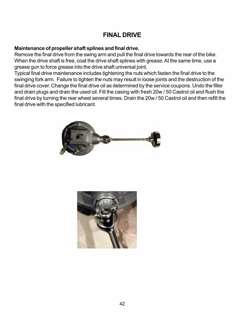
FINAL DRIVE
Maintenance of propeller shaft splines and final drive.Remove the final drive from the swing arm and pull the final drive towards the rear of the bike.When the drive shaft is free, coat the drive shaft splines with grease. At the same time, use agrease gun to force grease into the drive shaft universal joint.Typical final drive maintenance includes tightening the nuts which fasten the final drive to theswinging fork arm. Failure to tighten the nuts may result in loose joints and the destruction of thefinal drive cover. Change the final drive oil as determined by the service coupons. Undo the fillerand drain plugs and drain the used oil. Fill the casing with fresh 20w / 50 Castrol oil and flush thefinal drive by turning the rear wheel several times. Drain the 20w / 50 Castrol oil and then refill thefinal drive with the specified lubricant.

43
Chapter 7RUNNING GEAR
MOTORCYCLE AND SIDECAR FRAMES
The frame is the principal bearing element of the motorcycle to which all the units and assembliesof the motorcycle are attached. The motorcycle is furnished with a twin closed frame of weldedconstruction.
Rear suspension swing arm; 2-Rear fender; 3-Rear fender strap; 4-Spring and hydraulicshock absorber; 5-Saddle; 6- Saddle handle; 7- Motorcycle frame; 8- Leg adjusting fork;9,15-Sidecar frame legs; 10- Colett clamp; 11-Collet clamp screw; 12-Motorcycle stand;13-Foot brake pedal; 14-Sidecar brake lever; 16-Sidecar brake lever axle; 17-Rear colletbracket; 18- Rear bracket bolt; 19- Lever pins; 20- Lever; 21-Brake tie rod; 22-Brakedrum cover: 23-Sidecar wheel axle; 24-Protective cap; 25-Tie rod nut; 26-Sidecar fender;27-rubber member of body suspension.

44
SPRING LOADED HYDRAULIC SHOCK ABSORBER
The suspension features cam-type adjusters used for varying the preload of the supporting springsto suit the load and the road conditions. The degree of tension on the springs is adjustable allowingtwo positions. The first (lower) position corresponds to the load due to the motorcycle’s ownweight, the driver’s and one passenger’s (sitting in the sidecar) weight; the second (upper) positionof the adjuster corresponds to the maximum load.
When the motorcycle is used under the maximum load, adjust the spring in the sidecar wheelshock absorber simultaneously while adjusting the compression of the spring in the motorcycleshock absorbers.
Care of shock absorbers. Fill the shock absorber with 105 cm³ of hydraulic fluid. Each timeduring maintenance, check the bolts affixing the top and bottom end of the shock absorbers fortightness.

45
ADJUSTMENT OF SIDECAR INSTALLATION
The sidecar should be installed in a definite position relative to the motorcycle. The position isdetermined by the camber and toe-in of the motorcycle and the sidecar wheels. An incorrectlyaligned sidecar will drag the motorcycle to either sideand cause extensive tire wear. If the motorcycle is notstable on the road or is difficult to steer, check the align-ment. Checking and measuring the alignment should bedone on level ground.
Check toe-in of the motorcycle and the sidecar wheelswith two straight bars applied to the side faces of thewheels just below the axles. The toe-in should be 5 to 15mm or 3/16 to 9/16 in. at the front wheel. When adjust-ing, unbolt the top of the slanting legs fastening thesidecar to the motorcycle, slacken off the bolt clampingthe lower rear bracket, adjust the position of the bracketrelative to the rear tube of the sidecar frame to obtainnecessary toe-in of the wheels. Tighten up the boltfastening the bracket, adjust the length of the legs andsecure them with bolts.
Check the lean-out of the motorcycle using a level gaugeor protractor with a plumb bob and a ruler. Adjust thetwo inclined legs by screwing the forks in or out. Whenthe lean-out is correct, the rider will remain vertical whileriding on the local roads which may be slightly sloped toassist with water runoff.
Check the toe-in while the motorcycle is running on theroad. With the toe-in properly adjusted, the motorcyclewill not pull to either side while running at normal roadspeed. If it pulls to the right, increase the toe-in, if itpulls to the left, decrease the toe-in.
CAUTION: Double check for correct toe-in before making any change to lean-out.
0 to 3º lean out

46
FRONT FORK
The leading link front fork used on the Tourist and Patrol models use a front lever-type fork withtwo interchangeable spring-hydraulic shock absorbers.
The friction type steering damper is made up of two steel washers, moving and fixed, twofiber washers and tightening bolt with a head. Friction between the steel and the fiber washersmakes turning of the front fork more difficult.
WARNING: DO NOT OVER TIGHTEN THE STEERING DAMPER SINCE THE MOTORCYCLE WILL BECOME VERYDIFFICULT TO HANDLE.

47
Front fork of leading link type
1-Protective washer; 2- Seal; 3-Cross-piece; 4-Steering column stem nut; 5-Thrust washer; 6-Spring washer; 7-Tightening bolt; 8-Steering column stem; 9-Bearing nut; 10- Top ball radial thrustbearing; 11-Tightening nut; 12-Washer; 13- Leg cover with headlight bracket; 14-Steering columnbridge; 15-Front fender clip; 16-Front fender; 17-left fork leg tube; 18-spring and hydraulic shockabsorber; 19-Brake drum cover thrust link; 20-Wheel lever; 21-Moving ring; 22-Fixed ring; 23-Lower ball radial thrust bearing;

48
STEERING HEAD BEARINGS
The steering head bearings must be adjusted periodically to avoid excessive play which mightcause steering instability. When properly adjusted, the front fork should turn with just a hint ofbearing drag, but without free play or obvious resistance to turning.
WARNING: IMPROPER ADJUSTMENT OF THE STEERING HEAD (E.G. TOO TIGHT) WILL MAKE THE MOTORCYCLEVERY DIFFICULT TO STEER. THIS ADJUSTMENT IS CRITICAL FOR PROPER HANDLING OF ALL MODELS.

49
Chapter 8WHEELS AND TIRESThe Ural motorcycle is equipped with easily demountable wheels with the cast (aluminum) brakedrum on short spokes of the same size on the rear wheels and steel disc and machined hub on thefront wheel.
Removing wheels. To remove the front wheel, set the motorcycle on its stand, lift it by the frontwheel and put a rest under the front portion of the motorcycle frame. (You may want to purchase ascissor jack or bottle jack to carry along in the sidecar storage compartment. This will make iteasier to change any of the three wheels on the rig.) Slacken the nut of the union bolt at the end-piece base of the fork left-hand leg. Screw out the axle turning it clockwise (left-hand thread) andremove the wheel together with the front brake disc.
To reinstall the front wheel on the motorcycle follow the reverse order of the above operationsseeing to it that the brake disc evenly engages with the brake caliper.
To remove the rear wheel of the motorcycle, lift the motorcycle onto the center stand. Undo the rearwheel axle nut and take it off together with the washer, slacken off the nut on the union bolt of theleft-hand leg of the swinging arm, pull out the rear wheel axle with the help of a wrench bar andremove the wheel.
To reinstall the wheel on the motorcycle follow the reverse order of operations. Prior to reassem-bling, wipe the axle and grease it. Fitting the rear axle, turn it as you push it in to avoid jamming.
To remove the spare wheel, use the wrench from the tool kit that has two studs that fit the two holesin the round nut holding the luggage rack down.
Care should be taken to keep tires properly inflated. Check before riding when tires are cold. Donot overinflate tires.
Warning: Never interchange the front for the rear wheels.
WARNING: IMPROPER TIRE INFLATION WILL CAUSE ABNORMAL TREAD WEAR AND COULD RESULT IN UN-STABLE HANDLING. UNDER-INFLATION COULD RESULT IN THE TIRE SLIPPING ON THE RIM.

50
Front & Sidecar Rear tire pressure tire pressure
Check inflation pressure and inspect tread for punctures, cuts, breaks, etc., at least weekly if indaily use or before each trip, if used occasionally.
WARNING: RIDING WITH EXCESSIVELY WORN, UNBALANCED OR IMPROPERLY INFLATED TIRES IS HAZARDOUSAND WILL ADVERSELY AFFECT TRACTION, STEERING AND HANDLING. SAME AS ORIGINAL EQUIPMENT TIRESMUST BE USED. OTHER TIRES MAY NOT FIT CORRECTLY AND MAY BE HAZARDOUS TO USE.
BECAUSE TIRES, TUBES AND WHEELS ARE CRITICAL SAFETY ITEMS AND SERVICING OF THESE ITEMS REQUIRESSPECIAL TOOLS AND SKILLS, WE RECOMMEND YOU SEE YOUR IMWA DEALER FOR THESE SERVICES.
TIRE DATA
WARNING: FOR YOUR OWN PERSONAL SAFETY, TIRES AND TUBES MUST BE CORRECTLY MATCHED TO WHEELRIMS. SEE YOUR AUTHORIZED IMWA DEALER FOR FURTHER INFORMATION. MISMATCHING TIRES, TUBES ANDRIMS MAY RESULT IN DAMAGE TO THE TIRE BEAD DURING MOUNTING OR MAY ALLOW THE TIRE TO SLIP ON THERIM, POSSIBLE CAUSING TIRE FAILURE. IN ADDITION, USING TIRES OTHER THAN THOSE SPECIFIED MAY AD-VERSELY AFFECT MOTORCYCLE STABILITY. PROTECTIVE RUBBER RIM STRIPS MUST BE USED. TIRE SIZES AREMOLDED ON THE TIRE SIDEWALL. TUBE SIZES ARE PRINTED ON THE TUBE.
Ural tires that have been tested by the manufacturer to ensure compliance with DOT requirementsare available from your Authorized IMWA Dealer.
1.5 Bar 2.5 Bar
or 150 kPa or 250 kPa

51
The following tire data labels are mounted on the front frame of your Ural.
For motorcycle with sidecar , 19” tire
Front: 491 lb. (223 kg) with 4.00 x 19 tire, 19 x 3.00 rim, at 22 psi cold (1.5 Bar)Side: 304 lb. (138 kg) with 4.00 x 19 tire, 19 x 3.00 rim, at 22 psi cold (1.5 Bar)Rear: 577 lb. (262 kg) with 4.00 x 19 tire, 19 x 3.00 rim, at 36 psi cold (2.5 Bar)
WARNING: MAXIMUM INFLATION PRESSURE MUST NOT EXCEED SPECIFICATION ON TIRE SIDEWALL.
WARNING: WHEN TIRES ARE WORN TO A TIRE CENTER TREAD DEPTHS OF 3/32 IN, THEY SHOULD BEREPLACED.
WHEEL AND TIRE MAINTENANCE
During the pre-trip inspection, check air pressure in the tires (chapter 1).
Check axle and spokes for safe fastening, be sure to tighten the spokes or fasteners andeliminate play as soon as they get loose or demonstrate excessive play.
While lubricating, consult the Lubrication Chart in chapter 11.
WARNING: WHEEL TRUING INVOLVING MORE THAN 2 TURNS OF ANY SPOKE NIPPLE SHOULD BEACCOMPLISHED WITH THE TIRE DISMANTLED SO THAT SPOKE ENDS CAN BE CHECKED TO ENSURE NO SPOKESPROTRUDE INTO THE INNER TUBE.

52
Wheel ConstructionTwo adjustable tapered roller bearings are pressed into the wheel hub, which are prelubricated withLITOL-24 type grease. Depending on motorcycle versions, the wheels with aluminum cast brakedrum or disc type may be used. The adjustment of bearings is the same for both styles of wheel.
Adjustment of wheel bearings.
The wheel bearing life is greatly extended through properadjustment. Check the condition of bearings and adjust tight-ening of them every 5000 km. To adjust the bearings proceedas follows:- Remove the wheel from the motorcycle;- Fit the rear wheel axle (without protective cap), tighten itby nut with the aid of a bushing, 100 mm long, with 21 mm IDand 25…30 mm OD, or a set of bushing of given size.- Determine if there is a play by turning the axle (but not thewheel on the axle) and rocking it, slacken off the lock nut.- Screw the seal nut up to the limit, then release it by 1/6..1/8 of the turn so that the axle-bushing system rotates withoutplay, easily and without jamming. The overtightening of bear-ings is strictly prohibited.- Tighten the lock nut without effecting the bearing adjust-ment.- Pull the axle out.- Put the wheel onto the motorcycle.

53
Chapter 9BRAKES
BRAKES
The motorcycle is equipped with a hydraulic disc brake in front and manual shoe type brakes inthe rear and sidecar. The hydraulic disc brake consists of a caliper, brake pads and a wheel disc.The manual shoe type brake consists of a drum, a drum cover, shoes and lever activated cams.
The front wheel brake is of the hydraulic disc type.The sidecar wheel brake is connected to the rear brake pedal.The sidecar brake drum cover is secured on the sidecar wheel axle and is held from rotation by atorque stop. Sidecar brake shoes are interchangeable with the motorcycle rear brake shoes.The rear wheel brake is mounted in the final drive case, and is actuated via a mechanical linkageto the brake pedal.The brake shoes are provided with adjusting bolts to compensate for the wear of the shoe linings.The adjusting bolts of the brake shoes may be used for adjusting the gap between the brake shoesand the brake drum.For optimal performance of the brake, tighten the brake cable adjuster until there is just the slightestdrag on the wheel. Then back off the adjustment 1 or 2 turns.
For checking the gap, the cover of the brake drum and final drive crankcase are provided with aninspection hole, closed with a rubber plug.
WARNING: Never use the front brake to stop when the motorcycle is moving in reverse.Severe damage to the front brake caliper and mounting plate will occur.
REAR BRAKE ADJUSTMENT
The foot brake is adjusted by an adjusting nut situated on the rear end of the brake tie rods.Proceed to adjustment of the foot brake starting from the rear wheel, having first slackened the nuton the tie rod of the sidecar wheel brake. Then adjust the sidecar wheel brake by tightening thenut on the brake tie rod. After the foot brake has been adjusted properly, back up the nut on the tierod of the sidecar wheel brake by 2-3 turns to keep if from pulling to the right when applying thebrake.

54
Rear brake adjustment nut
Brakes should be “burnished in” during the initial running in period. Follow burnishing procedurescarefully. Make approximately 100 stops using 75% of full braking power. This can be done overseveral periods and need not be done in one session. Choose an area with clean, dry pavementand no obstructions. Travel in a straight line and apply both the hand (front) brake as well as thefoot (rear and sidecar) brakes.
After burnishing the brake shoes, adjust your brakes on each wheel to reduce the gap betweenshoes and drums. This procedure will ensure maximum braking performance during the running-inperiod and is essential before raising your top speed, after your Ural has been carefully run in(after 1,500 km).
WARNING: BECAUSE BRAKE PERFORMANCE IS A CRITICAL SAFETY ITEM, WE RECOMMEND THAT YOU SEEYOUR IMWA DEALER FOR THESE SERVICES.
BRAKES MUST BE INSPECTED FOR WEAR AS PER THE SERVICE COUPONS IF THE BRAKE SHOE FRICTIONMATERIAL IS 1/16 IN. THICK OR LESS (THE THICKNESS OF A NICKEL) THE SHOES MUST BE REPLACEDIMMEDIATELY. FAILURE TO REPLACE SHOES WHEN NECESSARY COULD RESULT IN BRAKE MALFUNCTION ANDPERSONAL INJURY. IF YOU RIDE UNDER ADVERSE CONDITIONS, STEEP HILLS, HEAVY TRAFFIC, ETC., MOREFREQUENT INSPECTION, 1,000 KM OR LESS, WILL BE NECESSARY.

55
The front disc brakes require periodic inspection, but do not require adjustment. The brake padscan be inspected by removing the dust shield from the top of the caliper and checking the thick-ness of the pads. The pads should be replaced when less the 1/8 inch of pad is remaining oneither pad. The brake hose should be inspected periodically for leaks and cracks along the lengthof the hose as well as the banjo fittings on either end.
WARNING: Never use any aftermarket brake hose for the front brake. Use only genuine Uralbrake hoses, failure to do so could result in front brake failure and voiding the warranty.

56
Brake Reservoir
Check the front brake reservoir every service. Wipe off all dirt and avoid any contamination of thebrake fluid in the reservoir. Refill the reservoir with only DOT approved 3 or 4 brake fluid. Becareful not to spill brake fluid on the paint, as damage to the paint may occur.
To check the brake fluid level in the reservoir, remove the two top screws on the reservoir. Removethe cover and the rubber gasket. Fill the reservoir to within 1/4 inch of the top. Squeeze the brakelever several times to ensure that any air that has been introduced is forced out of the system.Replace the rubber gasket, the cover and the two screws.

57
Chapter 11ELECTRICAL EQUIPMENTThe electrical equipment of the motorcycle includes power supplies, auxiliary instruments andelectric wiring.
Electric power supplies are a battery and an alternator with a built-in rectifier.
A single wire system is used for wiring the electric circuits, i.e. a single wire carries power to theelectrical devices and the frame and engine serve as the second wire (called the “ground”). Thenegative pole of the battery is connected to the motorcycle frame through the battery masterswitch. The alternator makes electrical contact to the motorcycle engine and frame through itsmounting bolts.
Battery supplies electric power to all the systems of the motorcycle when the engine (and alterna-tor) have stopped.
An alternator with a built-in rectifier is driven by the engine camshaft driven gear. The alterna-tor is secured with two studs on the engine crankcase. At the drive side, the alternator cover is sodesigned that by turning the alternator on the studs, the backlash adjustment of the gear mesh gapcan be made.
Electric horn. The motorcycle is equipped with a horn which sounds when the ignition is on andthe horn button is pressed. The horn can be tuned for loudest performance with an adjustingscrew located at the rear portion of the horn body.
Headlight. A 7" diameter DOT approved sealed beam headlight is used on the Ural. Adjust it sothat the high-beam is horizontal when the motorcycle is in its normal loaded condition.
The stop light switch is secured on the frame bracket by means of two nuts. If the stop lighteither stays on or doesn’t come on, loosen the nuts and adjust the stop light switch position eitherup or down on the frame & retighten the two nuts.
Sidecar SpotlightSwitch
58
The sidecar spotlight, if equipped, is located on left side of the front of the sidecar. It is operatedby activating the switch located just behind the spotlight. The spotlight can be aimed by moving thelever at the rear of the spotlight. Only use the spotlight when the motorcycle engine is running,otherwise the battery may become discharged.WARNING: Never tap into the spotlight circuit to add accessories. Damage to the motorcycleelectrical system may result.
Electrical Circuits
Lead acid batteries such as those found in motorcycles are designed for a charging voltage of14.25 volts. Batteries which are subjected to greater than 14.25 volts for extended periods of timecan suffer permanent damage due to the electrolyte boiling dry. Charging voltage of less than14.25 volts will result in an inadequate charge delivered to the battery.
Automotive batteries operate at 12 volts. This is not enough voltage to harm people in any way.However, the battery stores a large amount of electricity in the form of electrons. If the electronsare allowed to flow from the battery without restriction, then the wires carrying the electricity willbecome hot enough to melt. The melting wires are extremely dangerous and can easily burn you.
Most problems in automotive electrical circuits are caused by poor connections. Make sure that allconnection points are clean and tight.
If the flow of electricity through a wire is interrupted due to a break in the wire or a poor connec-tion, then the circuit is said to be “an open circuit”
The flow of electricity through a circuit always takes the path of least resistance. If there is anaccidental path of extremely low resistance created in a circuit, the circuit is said to have a “shortcircuit” A short circuit will usually result in the melting of the fuse protecting that circuit.
ELECTRICAL EQUIPMENT MAINTENANCE
During the daily preventive inspection, check the functioning and the condition of the electricalequipment. Inspect and or replace the spark plugs and ignition leads as required in the ServiceCoupons. The gap is readjusted by bending the end of the side electrode.
Care of alternator. In the course of daily inspection, check the fastening of wires to the alternatorterminals, fastening of the alternator on the engine crankcase, backlash of the gears (by listening).In case of too little backlash of the drive gear, excessive wear and overheating of the alternatorbearings take place.
Check for proper tightening of:• nuts of the binding post bolts• the alternator clamping screws• the alternator fastening nutsas often as outlined in the Service Coupons.
59
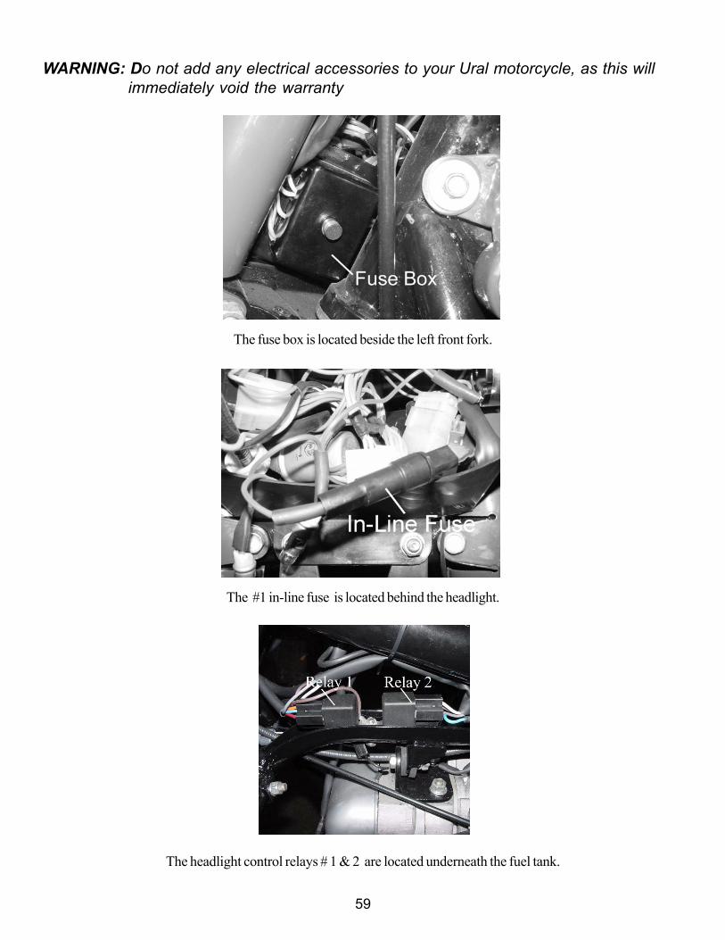
WARNING: Do not add any electrical accessories to your Ural motorcycle, as this willimmediately void the warranty
The fuse box is located beside the left front fork.
The #1 in-line fuse is located behind the headlight.
The headlight control relays # 1 & 2 are located underneath the fuel tank.

60
61
Chapter 12MAINTENANCE OF MOTORCYCLEMaintenance should be performed after the specified total kilometers run irrespective of themechanical condition of the motorcycle.
Different service duties and mechanical condition of the motorcycle may necessitate a change inthe intervals.
The Lubrication Chart indicating lubrication points of the motorcycle is given in Fig. 35. A sum-mary of lubrication maintenance is given in the lubrication chart.
Cosmetic Maintenance
The enjoyment and resale value of your vehicle is greatly enhanced by consideration to the “look”and cosmetic perfection of your vehicle. Due to the numerous metal surfaces on a sidecar rig,special care must be taken to prevent rust from occurring and/or to removed any rust or oxidation.
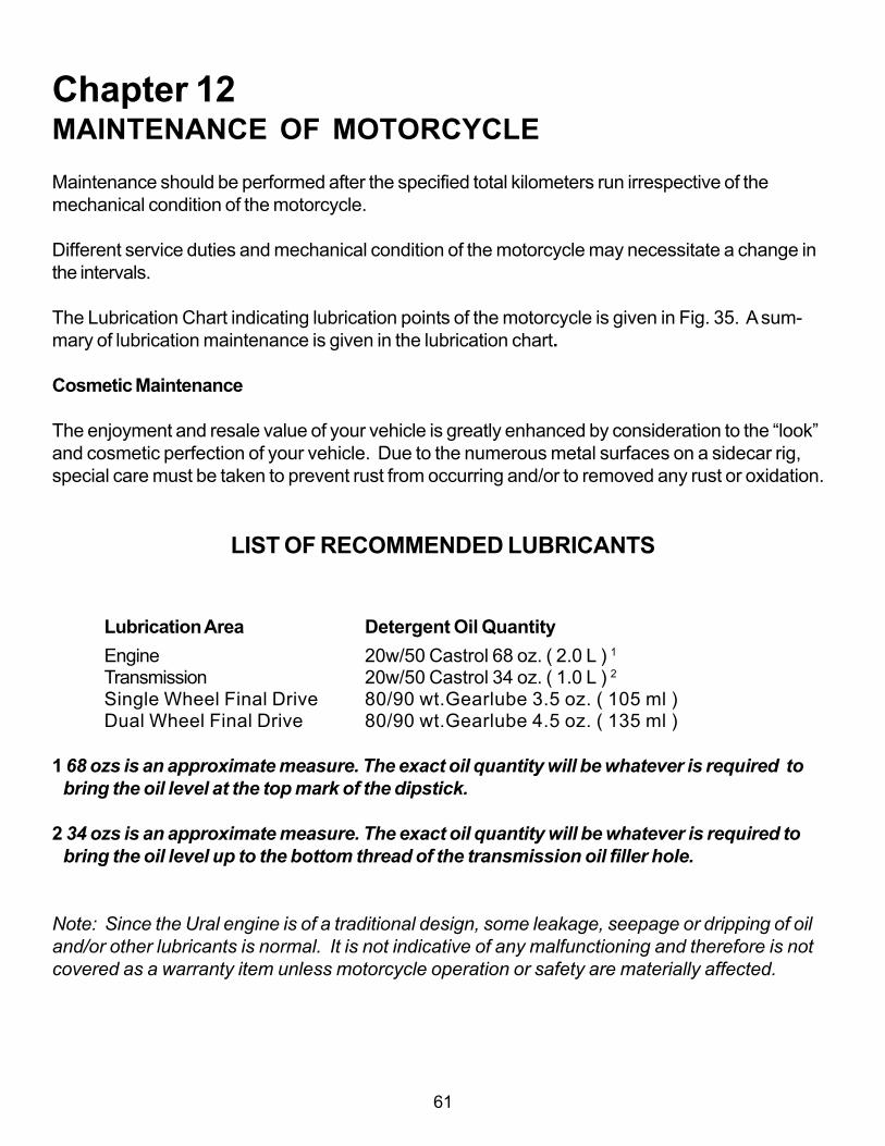
LIST OF RECOMMENDED LUBRICANTS
Lubrication Area Detergent Oil QuantityEngine 20w/50 Castrol 68 oz. ( 2.0 L ) 1Transmission 20w/50 Castrol 34 oz. ( 1.0 L ) 2Single Wheel Final Drive 80/90 wt.Gearlube 3.5 oz. ( 105 ml )Dual Wheel Final Drive 80/90 wt.Gearlube 4.5 oz. ( 135 ml )
1 68 ozs is an approximate measure. The exact oil quantity will be whatever is required to bring the oil level at the top mark of the dipstick.
2 34 ozs is an approximate measure. The exact oil quantity will be whatever is required to bring the oil level up to the bottom thread of the transmission oil filler hole.
Note: Since the Ural engine is of a traditional design, some leakage, seepage or dripping of oiland/or other lubricants is normal. It is not indicative of any malfunctioning and therefore is notcovered as a warranty item unless motorcycle operation or safety are materially affected.

62
63
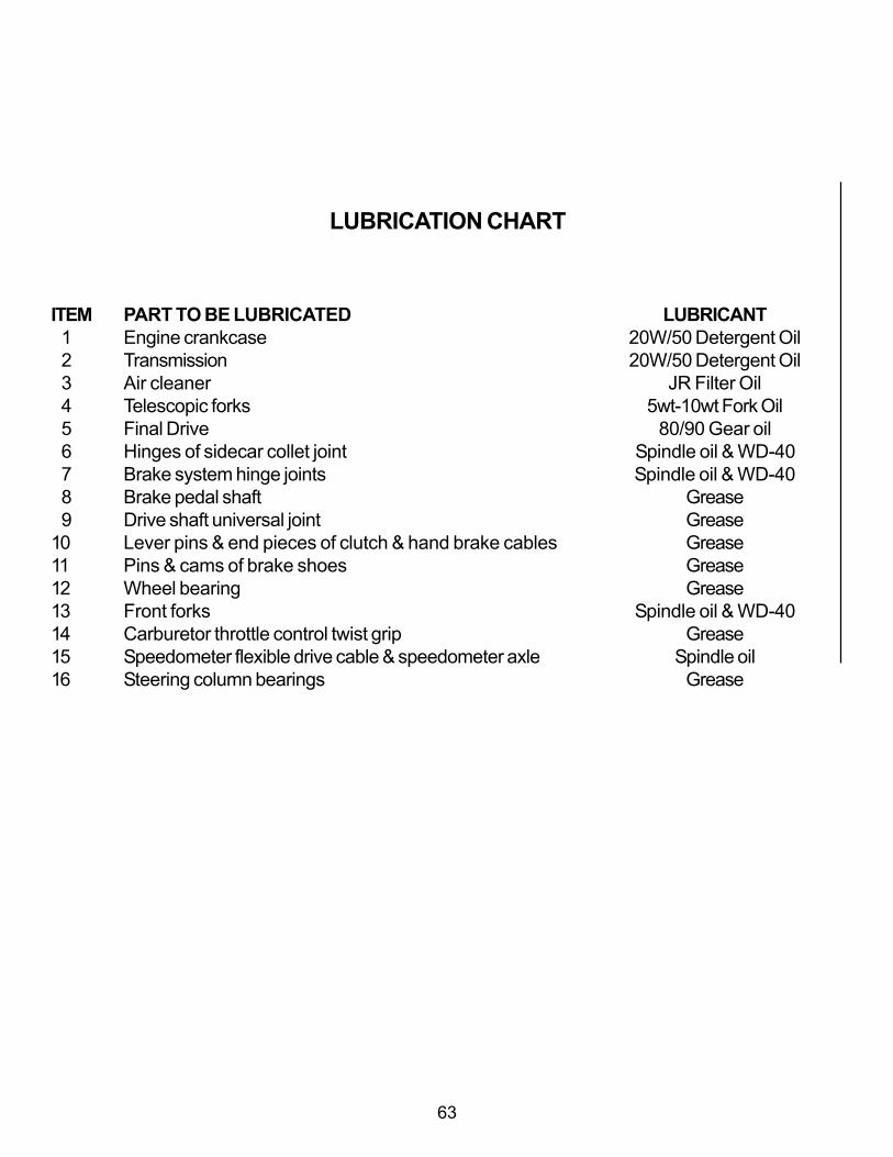
LUBRICATION CHART
ITEM PART TO BE LUBRICATED LUBRICANT 1 Engine crankcase 20W/50 Detergent Oil 2 Transmission 20W/50 Detergent Oil 3 Air cleaner JR Filter Oil 4 Telescopic forks 5wt-10wt Fork Oil 5 Final Drive 80/90 Gear oil 6 Hinges of sidecar collet joint Spindle oil & WD-40 7 Brake system hinge joints Spindle oil & WD-40 8 Brake pedal shaft Grease 9 Drive shaft universal joint Grease10 Lever pins & end pieces of clutch & hand brake cables Grease11 Pins & cams of brake shoes Grease12 Wheel bearing Grease13 Front forks Spindle oil & WD-4014 Carburetor throttle control twist grip Grease15 Speedometer flexible drive cable & speedometer axle Spindle oil16 Steering column bearings Grease
64
REQUIRED LUBRICATION
The Ural has been certified for EPA with SAE 20W/50 petroleum based detergent oil. This oilis used in both the engine and transmission.
CARE OF MOTORCYCLE PAINT
When washing the motorcycle, use a weak stream of cold or slightly heated water. Never use apressure washer! Do not remove dust and mud by rubbing the surface with a dry cloth as sandparticles will degrade the surface and the paint will rapidly lose its brilliance. While washing, donot use soda solution, kerosene, citric acids or mineral oils. If the surface is stained with mineraloil, degrease by wiping with a rag. If after removal of mud and dust with a jet of water, some dirtis left on the surface, remove it with the help of a sponge, a soft hair brush or a flannel and water,but not allowing separate water drops to dry out on the surface. Finally, polish the painted sur-faces with a dry soft flannel.
To repair painted areas, each motorcycle is furnished with a bottle of matching touch up paint.
For patching proceed as follows:• clean the surface with turpentine• rub the damaged spot with a waterproof abrasive cloth and water rub thoroughly• paint using a soft brush or a spray gun.
After patching let the surface dry in air for 15 min, then proceed with drying at 212°F-248°F/100°C-120°C with the aid of heat reflector or an electric lamp until the coat is perfectly dry.
Bear in mind that enamels are flammable. Color match may not be perfect due to humidity, fad-ing, temperature and other variables.
The painted surfaces of the motorcycle feature natural gloss. In case some dull spots appear,remedy them by polishing as follows. Take a solution of wax polishing compound and havingwashed the dull spots thoroughly, smear a thin film of the compound with a soft wad (cotton,cotton gauze or flannel) over the surface. Rub the polishing compound making circular motionswith the wad. In 3 - 5 min. of drying, wipe the surface with a clean dry piece of cloth or flanneluntil luster appears.

65
PRESERVATION AND STORAGE
If the motorcycle is put in storage for the season, arrange it on supports and proceed with thepreservation treatment. Check that the wheel tire pressure is within specifications. Store the motor-cycle away from acids, alkalis, mineral fertilizers and other harmful substances.
Prior to placing it in storage, clean the bike thoroughly, drain the carburetors, or start the engineand let it run with the gasoline cock closed to remove gasoline in the float chambers of carburetors.
Then spray storage oil (WD-40) into each cylinder through the spark plug holes. Turn the crank-shaft by depressing the kick lever pedal to distribute lubricant over the interior of the cylinders.Lubricate the surfaces of chrome and zinc plated parts with a rust inhibitor. Smear all the pointsprovided with grease cups with commercial grease. Seal the outlet holes of the mufflers.
Before starting a trip on the motorcycle that was under preservation, proceed with the jobs listed inthe section “Pre-Trip Preliminaries”.
Winter Considerations
Motorists in many areas of the US experience the use of salt and other chemicals that are appliedto road surfaces in the winter.
Salt or other caustic chemicals should always be removed from your bike’s surfaces with freshwater as soon as possible.
Undercoating of fenders is recommended for those areas with salt and/or fine gravel or sand. Seeyour dealer for details.
BATTERY
Storage batteries on the motorcycle should function at ambient air temperature from -40°C to plus60°C/ 40°F to 140°F.
As the battery is in service:• regularly check the voltage for 13.8 - 14.2 V• do not allow the battery to discharge.• use only distilled water to maintain the normal level of electrolyte.• coat bolts, nuts, washers and tips with petroleum jelly or battery grease. Use two wrenches for
clamping or undoing the nuts to avoid breaking battery parts.

66
Warning: Do not short the terminals together to check for sparking.
Before storage, fully charge the batteries, wash the battery surface with water and wipe dry, cleanthe bolts and nuts of dirt.
WARNING: BATTERIES CONTAIN SULFURIC ACID WHICH CAN CAUSE SEVERE BURNS. AVOID CONTACT WITHSKIN, EYES OR CLOTHING. ANTIDOTE: EXTERNAL — FLUSH WITH WATER. INTERNAL — DRINK LARGEQUANTITIES OF WATER FOLLOWED BY MILK OF MAGNESIA, VEGETABLE OIL, OR BEATEN EGGS. CALL DOCTORIMMEDIATELY.Caution: When charging the battery, disconnect the positive terminal (+) from the battery toprevent damage to the electrical components Never jump-start the motorcycle!
WARNING: BATTERIES PRODUCE EXPLOSIVE HYDROGEN GAS AT ALL TIMES — ESPECIALLY WHEN BEINGCHARGED. KEEP CIGARETTES, OPEN FLAME, AND SPARKS AWAY FROM BATTERY AT ALL TIMES. VENTILATEAREA WHEN CHARGING BATTERY. ALWAYS PROTECT HANDS AND PROTECT EYES WITH SHIELD OR GOGGLESWHEN WORKING NEAR A BATTERY OR ACID. KEEP BATTERIES AND ACID OUT OF THE REACH OFCHILDREN!
CAUTION: If battery is filled to a higher level than specified, some of the solution will beforced out through the vent tube when battery is charging. This will not only weaken thesolution, but also may damage parts near the battery. To prevent battery case damagecaused by pressure buildup, be sure vent tube is properly routed and not kinked or ob-structed.
LIST OF INDIVIDUAL TOOL SET,SPARE PARTS, ACCESSORIES & DOCUMENTS
DESCRIPTION QTY DESCRIPTION QTY
Tools Accessories 1. Wrench 7 x 8 1 1. Air Pump 1 2. Wrench 10 x 12 1 2. Air Pressure Gauge 1 3. Wrench 13 x 14 1 3. Ignition keys 2 4. Wrench 14 x 17 1 5. Wrench 19 x 22 1 6. Socket wrench 10 x 12 1 7. Socket wrench 10 x 13 1 Set of Spares 8. Socket wrench 19 x 21 1 9. Wrench 27 mm 1 1. Oil filter element 110. Double head wrench 1 2. Fuses 211. Spanner wrench 1 3. Touch up paint 112. Spanner wrench assembly 113. Screwdriver 150 mm 1 Documents14. Screwdriver 100 mm 1 1. Owner’s Manual 1

67
15. Punch 116. Allen wrench 117. 22mm Round wrench 1
(Patrol only)

68
This page left intentionally blank

69
Chapter 13GEAR UP AND PATROL MOTORCYCLE WITHENGAGEABLE SIDECAR DRIVE
DESCRIPTION
When engaged by the operator for “off-road” use, the sidecar wheel is driven by a drive shaftconnected with the motorcycle main drive with a universal joint.
Sidecar Drive Disengaged Sidecar Drive Engaged
NOTE: the sidecar drive should only be engaged when the motorcycle is stopped, and onlywhen venturing “off-road”
HANDLING DIFFERENCES FROM THE SINGLE WHEEL DRIVE
When the sidecar wheel is engaged, the motorcycle handles differently from the standard (singlewheel drive) motorcycle. When the rear wheel and sidecar wheel are “locked” together on pavedsurfaces, maneuvering is very difficult. Forcing the rig to turn on paved surfaces with the sidecardrive engaged is extremely hazardous and can result in loss of control of the motorcycle. It alsovoids the warranty.
The dual wheel drive should be engaged whenever poor traction is encountered in any off-roadcondition such as mud, snow, streams, rocks, gravel, loose dirt, sand, etc. In these conditions theextra traction afforded by the sidecar wheel will be very helpful, especially if some weight is alsoadded to the sidecar. Some difficulty in making sharp turns may still be noticed.

70
SIDECAR MAINTENANCE
Check before driving that the final drive swing arm, propeller shaft fork and sun gear flange arebolted tightly.
Grease the drive shaft splines sufficiently as outlined in the service coupons. Do not over greasethe drive shaft splines as this may prevent the drive shaft from moving freely in the hub.
The sidecar wheel bearing requires periodic greasing.
WARNING: The canister is not to be used for fuel or drinking water. The ammunition box is notto be used for the storage of live ammunition.
NOTE: Never leave the spotlight on when the motorcycle is not running. A dead battery mayresult.

71
Chapter 14LEARNING TO RIDE THE URAL MOTORCYCLE WITHSIDECAR ACCESSORY
The Ural sidecar motorcycle, since it has three wheels, behaves quite differently from either a solomotorcycle or a car. For these reasons the following label has been attached to your motorcycletank:
WARNING: LEFT-HAND AND RIGHT-HAND TURNS MAY BE DANGEROUS. EXCESSIVE SPEED AND ANUNWEIGHTED SIDECAR MUST BE AVOIDED.
The bottom line is that, like any other motor vehicle, if the Ural is driven beyond its design limits,you can get hurt. Properly driven, since you have the added stability of the third wheel in case ofsand, ice or slippery road conditions, the Ural will give you a much safer ride than a solo motor-cycle.
Finally, you will enjoy the fact that the Ural will not expose you to tipping over at stop signs, whichhas happened all too frequently to beginners as well as experienced solo motorcycle drivers.
This manual is included with each new Ural sidecar motorcycle outfit. Before driving your newUral , carefully study this manual from cover-to-cover, fill in the exam questions, review the manualto check your answers and practice all the maneuvers outlined in the manual before going out intotraffic.
If possible, an experienced sidecar driver (preferably your Authorized IMWA dealer) should ridealong during your first ride. If not, put about 100 LB of ballast in the sidecar during your initialtraining. Although an experienced driver can safely drive the Ural with an empty sidecar a begin-ner should always have ballast or a passenger in the chair.
Check with your local IMWA Dealer to find out your particular state’s sidecar driver’s licenserequirements.
72
When you accelerate, the Ural will pull slightly to the right due to the inertia and drag of the sidecar.
When you let off the gas it will pull slightly to the left due to the inertia of the sidecar.
Note: The Patrol with engageable sidecar wheel handles differently with the sidecar driveshaftengaged and cannot turn on paved roads. For this reason, the sidecar drive must only be en-gaged when operating the vehicle off-road or where snow, ice and mud conditions are encoun-tered on road.
The best way to make friends with your Ural is to take it to a large, paved, non-congested parkinglot. Practice starting and stopping from various speeds, shifting up and down, accelerating anddecelerating in each gear, turning right and left at slow-to-medium speeds.
Finally, practice lifting the sidecar. To do this drive in a clockwise circle about 20 feet in diameter.Gradually increase your speed until the sidecar wheel lifts from the surface 6 - 12 inches. Thenroll off the throttle and ease steering pressure on the grips so it gradually comes back down. Re-peat doing this until you feel comfortable with the wheel in the air. Remember, the moment you rolloff the throttle it will come down. When you have mastered “flying the chair” to the point where youcan keep it in the air for a full circle you will have a good feel for the speed and turn radius that willlift the sidecar. Then carefully experiment with larger and smaller circles.
If, after gaining proficiency with the Ural , you plan to drive on the street with an empty sidecar, goback to the parking lot and practice the above maneuvers with an empty sidecar. You’ll find that thesidecar will lift much more readily when it is empty, especially if you enter a decreasing radius turn(such as a freeway off ramp) at too high a speed. This is why we recommend generally carryingabout 100 lbs. or more in the sidecar.

73
SAFE OPERATING RULES
Before operating your Ural it is your responsibility to read and follow operating and maintenanceinstructions in this manual and follow these basic rules for your personal safety.
• Know and respect the Rules of the Road in your state.• Use only IMWA approved parts and accessories.• Gasoline is extremely flammable and is explosive under certain conditions.• Refuel in a well ventilated area with the engine stopped. Do not smoke or allow open
flames or sparks when refueling or servicing the fuel system. Always close the fuelsupply valve when the engine is not running to prevent flooding of the carburetors. Donot overfill fuel tank. Fill tank slowly to prevent fuel spillage. Leave air space to allow forfuel expansion. Do not fill more than about an inch below the lower edge of the tank filler.
• Motorcycle exhaust contains poisonous carbon monoxide gas. Do not inhale exhaust gases and never run the engine in a closed garage or confined area.
• Before starting engine, check for proper operation of brake, clutch, shifter,throttle controls, correct fuel and oil supply.
• A new motorcycle must be operated according to a special break-in procedure (see Running-In The New Motorcycle).
• Operate the motorcycle only at moderate speed and out of traffic until youhave become thoroughly familiar with its operation and handlingcharacteristics under all conditions. If you are an inexperienced rider werecommend that you obtain information and training in correct motorcycleriding technique.
• Do not exceed the legal speed limit or drive too fast for existing conditions.Always reduce speed when poor driving conditions exist. High speedincreases the influence of any other condition affecting stability and thepossibility of loss of control.
• Pay strict attention to road surfaces and wind conditions. Any two or three-wheeled vehicle may be subject to upsetting forces. Wind blasts from passing trucks,
holes in the pavement, rough road surfaces, rider control error, etc., may influence the handling characteristics of your motorcycle. Should this happen, reduce speed and guide the motorcycle with a relaxed grip to a straightaway position. Do not brake abruptly or force the handlebars as this may aggravate an unstable condition. New riders should gain experience under various conditions while driving at moderate speeds.
• Operate your motorcycle defensively. Remember, a motorcycle does not afford the same protection as an automobile in an accident.
• Wear an approved helmet, clothing and footgear suited to motorcycle riding. Bright orlight colors are best for greater visibility in traffic especially at night. Avoid loose flowing
garments and scarves.• The exhaust pipes and mufflers get very hot when the engine is running and remain
too hot to touch for some time after the engine is shut off.• Wear clothing that will completely cover the legs when riding and avoid
contact with the exhaust system.• Do not allow others, under any circumstances to operate your motorcycle
74
unless you are certain that they are experienced, licensed riders and arefamiliar with the operation of your particular motorcycle.
• When leaving the motorcycle unattended, remove ignition key from switch.Protect your motorcycle against theft.
• Safe motorcycle operation requires mental awareness and good judgmentcombined with a defensive driving attitude. Don’t allow fatigue, alcohol ordrugs to endanger your safety or the safety of others.
• Maintain your motorcycle in proper operating condition in accordance withthe service coupons in this Owner’s Manual. Particularly important to motorcyclestability is the tire inflation pressure, tread condition, and proper adjustment ofwheel bearings and steering head bearings.Do not operate motorcycle with loose, worn or damaged steeringsystem or front or rear suspension system as handling will be adverselyaffected. Contact your dealer for repair of steering or suspension systemwear or damage.
• Do not tow a trailer.• At street intersections, give the right-of-way to the vehicle on your right. Do
not presume too much when you have the right-of-way, the other drivermay not know you have it.
• Always signal when preparing to stop or turn.• All traffic signs, including those used for the control of traffic at
intersections, should be obeyed promptly and to the letter. SLOW DOWNsigns near schools and CAUTION signs at railroad crossings shouldalways be observed and your actions governed accordingly.
• Never anticipate a traffic light. When a change is indicated from GO toSTOP (or vice versa) in the traffic control systems at intersections, awaitthe change.
• When intending to turn to the left, give signal at least 100 feet beforereaching the turning point. Move over to the centerline of the street (unlesslocal rules require otherwise), slow down passing the intersection of thestreet and then turn carefully to the left.
• In turning either right or left, watch for pedestrians as well as vehicles.• Do not leave the curb or parking area without signaling and seeing that
your way is clear to drive into moving traffic. A moving line of traffic hasthe right-of-way.
• See that your license tags are installed in the position specified by law andthat they are clearly visible under all conditions. Keep them clean.
• Ride at a safe speed — a speed consistent with the type of highway you areon, and always note whether the road is dry, oily, icy or wet. Each varyingcondition on the highway means adjusting your speed accordingly.

75
Chapter 15URAL MOTORCYCLES / WARRANTY AGREEMENTIrbit MotorWorks of America, Inc., (IMWA, Inc.) warrants to the first retail purchaser of the URAL® motorcyclefrom an Authorized IMWA Dealer and each subsequent owner that the motorcycle is free from defects in materialsand workmanship for the period stated below.
To Qualify For This Warranty• The URAL® motorcycle must be purchased from a Dealer within the United States who is authorized by
IMWA, Inc. to sell motorcycles. (See www.imz-ural.com for the authorized IMWA Dealer list)• Prior to delivery to the purchaser, the Dealer who is authorized by IMWA, Inc. to sell motorcycles must perform
set-up and pre-delivery service.
Warranty Time Period• Duration: two (2) years parts and labor.• There is no mileage limitation.• Coverage begins the date the motorcycle is sold to the first retail purchaser and the warranty registration card
is received by IMWA, Inc.
Warranty Coverage• IMWA, Inc. will repair or replace, at its options, any part (including parts of the emission control systems) that
is found to be defective in material or workmanship under normal use for the applicable time period.• In cases when warranty repair takes longer than 14 days, the warranty time period (see Warranty Time
Period) is extended for the time period of repair, during which the motorcycle could not been ridden due tofailures.
• IMWA, Inc. provides warranty for spare parts for the following period of time starting from the time of purchaseof the parts by a Dealer or retail customer.
1. Engine – 12 months2. Gearbox – 12 months3. Final drive – 12 months4. Alternator – 6 months5. Electric starter – 6 months6. Ignition – 6 months7. The rest of the motorcycle parts and parts assemblies - 30 days
The above applies ONLY in cases when Dealer or retail customer identifies defects before using parts and/or assembliesor these defects are identified during performance AND provided these parts have been properly installed by IMWA,Inc. or authorized IMWA Dealer.
• IMWA, Inc. will reimburse non-IMWA repair shops performing warranty repair for labor only if all the warrantyprocessing and approval procedures are completely fulfilled and/or carried out according to IMWA, Inc. guidelinesstated in the Warranty Claim Filing Procedures (see Warranty Claim Filing Procedures).
Warranty Terms – Dealer Demo BikesWarranty term for the retail buyer begins on the day that title transfers to the first retail purchaser. Thus, during theperiod a Dealer uses a bike for demonstration or show purposes, the warranty will be honored to the Dealer,provided proper maintenance procedures are followed during the demonstration period. If the Dealer sells themotorcycle to another Authorized IMWA Dealer, the warranty will continue, and the limited time warranty (describedabove) will begin on the day that title transfers to the first retail purchaser.The exception to the above is if a motorcycle has over 1,500 km on it at the time of transfer to the retail buyer, thebike remained on the Dealer’s floor for over 12 months from the time of purchase from IMWA, Inc. or if the Dealer

76
has voided the warranty through improper maintenance, usage, modifications, etc. Any failure of the speedometerassembly on any floor models will require the defective speedometer assembly to be returned to IMWA, Inc. inRedmond, WA. In any of the above cases, Dealer’s State Law and mileage requirements will determine whetherthe sale of a demonstrator motorcycle shall be considered new or used.
Modifications of IMWA, Inc. Limited Warranty for URAL® Motorcycles forCommercial Uses
All aspects of the normal non-commercial warranty apply except:
1. Parts and labor coverage limited to the first 10,000 km of mileage or one (1) year, which ever comes sooner(rather than limited mileage).
2. Parts only coverage limited to the second 10,000 km of mileage (up to 20,000 total km) or two (2) years,whichever comes sooner (rather than unlimited mileage).
3. All scheduled service work outlined in the service coupons at the end of the Owner’s Manual must be performedat an Authorized URAL® Dealer or a service facility pre-approved in writing by IMWA, Inc.
Note: Copies of all completed service coupons must be sent to IMWA, Inc. within 30 days of completion of eachcoupon. Failure to adhere to this requirement will void the warranty.
4. All personnel who operates the motorcycle must sign a statement that they have studied the Owner’s Manualand have gone through the sidecar motorcycle driving practice before taking the commercially outfitted URAL®outfit on the public roads.
A copy of a signed and dated statement of completion by each driver and instructor must be sent to IMWA, Inc.within 30 days of completion of training. Failure to adhere to this requirement will void the warranty.
Warranty DisclaimersLimitations & Exclusions
Disclaimer of Consequential Damage & Limitation of Implied Warranties
Irbit MotorWorks of America, Inc. disclaims any responsibility for:• Loss of time due to warrantable issue• Loss of use of motorcycle• Transportation expenses• Any other incidental or consequential damage (i.e. storage)
Duration of Implied WarrantiesAny implied warranties, including the implied warranty of merchantability and fitness for a particular purpose are limitedto the duration of this written warranty.
State Laws May VaryThe previous listed limitations or exclusions may not apply to a motorcycle because of state laws. Some states may notallow limitations on how long an implied warranty lasts. Some states may not allow exclusion or limitation of incidental orconsequential damages.
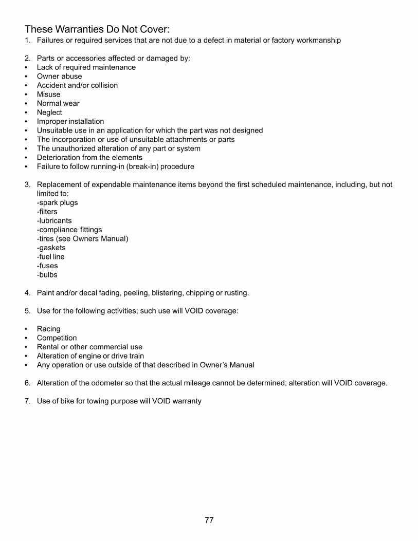
77
These Warranties Do Not Cover:1. Failures or required services that are not due to a defect in material or factory workmanship
2. Parts or accessories affected or damaged by:• Lack of required maintenance• Owner abuse• Accident and/or collision• Misuse• Normal wear• Neglect• Improper installation• Unsuitable use in an application for which the part was not designed• The incorporation or use of unsuitable attachments or parts• The unauthorized alteration of any part or system• Deterioration from the elements• Failure to follow running-in (break-in) procedure
3. Replacement of expendable maintenance items beyond the first scheduled maintenance, including, but notlimited to:-spark plugs-filters-lubricants-compliance fittings-tires (see Owners Manual)-gaskets-fuel line-fuses-bulbs
4. Paint and/or decal fading, peeling, blistering, chipping or rusting.
5. Use for the following activities; such use will VOID coverage:
• Racing• Competition• Rental or other commercial use• Alteration of engine or drive train• Any operation or use outside of that described in Owner’s Manual
6. Alteration of the odometer so that the actual mileage cannot be determined; alteration will VOID coverage.
7. Use of bike for towing purpose will VOID warranty

78
Dealer’s and Owner’s Responsibilities
Dealer Is Responsible to:• Thoroughly check and road test new units before delivery.• Fill out (Please Print!!!), sign and send Warranty Registration and Card of Delivery to IMWA, Inc.
within 3 business days of the sale of Motorcycle.• Accept all eligible motorcycles for warranty service regardless of selling Dealer.• Keep records of all warranty work.• Attend service schools as provided by IMWA, Inc.• Submit warranty claims to IMWA, Inc. IN WRITING within 10 business days of the repair date.• Obtain authorizations for warranty repairs from IMWA, Inc. when estimated cost will exceed $100.00
(see Advance Warranty Authorization).• Send failed parts and/or parts assemblies for an inspection to IMWA, Inc. within 3 (three) business days
upon IMWA’s request at IMWA,Inc. shipping expense.• Provide digital pictures of failed parts and/or parts assemblies immediately upon IMWA’s request.
Customer Is Responsible to:• Operate and maintain the motorcycle according to the IMWA, Inc. Owner’s Manual and service schedule.• Retain all service records for future reference.
Warranty Filing & Processing
Warranty Claims Filing ProcedureIMWA, Inc. will compensate Dealer for his labor based on authorized procedures only and at the published flatrate schedule (Appendix B) applied to the Dealer’s approved shop hourly rate.
1. Dealer will fax a warranty parts request to IMWA, Inc. on a Warranty Claim Form (Appendix A) for allwarranty parts.
2. Irbit MotorWorks of America, Inc. will review and when approved, will ship parts within 48 hrs and notifyDealer if repair will be covered under factory warranty.
3. Dealer must submit claims for labor reimbursement within 10 business days upon receipt of warrantyparts and completion of authorized repair.
4. All submitted claims for labor reimbursement must fall within published flat rate schedule (Appendix B) tobe approved.
5. Parts credit will be issued to the Dealer’s account before the 10th of the month.6. Warranty repairs estimated to exceed $100.00 in parts and labor must receive prior approval from
IMWA, Inc.7. Any repair that involves final drive, gearbox or internal invasive examination of engine must
receive prior approval from IMWA, Inc.
Engines, Gearboxes and Final Drives will be replaced on warranty only after the Dealer hasaccomplished the following:
1. A qualified IMWA trained technician has completed a thorough external examination, documentedfindings and has faxed/e-mailed it to IMWA, Inc. with comments of technician
2. IMWA, Inc. technical staff has reviewed and discussed the problem with the Dealer’s technician3. IMWA, Inc. issues Return Merchandise Authorization No. and call tag after authorizing return of item and
faxes it to Dealer

79
After IMWA, Inc. inspection of engine or gearbox or final drive:
1. If engine/gearbox/final drive is found to be defective due to factory parts or assembly failure, theappropriate warranty order will be processed and the flat rate for removal and re-installation of theengine/gearbox/final drive will be authorizedFailed engines/gearboxes/final drives will be warranted utilizing the following optionsat IMWA’s discretion:
• replacement with new engine/gearbox/final drive• replacement with factory refurbished engine/gearbox/final drive• repair utilizing new parts or parts assemblies
Factory refurbished engines/gearboxes/final drives are guaranteed to be refurbished to manufacturer’sspecifications.
2. If engine/gearbox/final drive is not defective but inoperable or less than optimal due to lack of easilydiagnosed misalignments and/or normal adjustments or is severely out of adjustment from poor workor understanding, the warranty claim will be denied and the Dealer will be charged for all shipping andadjustments at $35.00 IMWA Inc. hourly rate.
Notes:
• Dealer must notify IMWA, Inc. in writing upon receipt of any motorcycle which may involve over 30 days ofshop time including order and receipt time for parts, service time and delivery time. If Dealer fails to notifyIMWA, Inc. in such a case, Dealer will be solely responsible for any forced motorcycle repurchase thatoccurs and may be subject to termination of IMWA, Inc. Dealership.
• IMWA, Inc. reserves the right to perform warranty work at its expense on any motorcycle.Dealer agrees to properly package and promptly ship any defective item that IMWA, Inc.requests to be returned.
• Do Not Ship Batteries, Seals, Gaskets or Oils to IMWA, Inc. Dispose of them according to locallaws. Any questions about returning warranty items, contact IMWA, Inc.
• Defective and failed parts that were replaced by warranty are to be held at the Dealership for90 days.
• Dealer must send failed parts and/or parts assemblies for an inspection to IMWA, Inc. within 3 (three)business days upon IMWA’s request at IMWA, Inc. shipping expense.
• Dealer must provide digital pictures of failed parts and/or parts assemblies immediately upon IMWA’srequest.
Warranty ShippingAll warranty parts are shipped by UPS Ground or Priority Mail (USPS) paid by IMWA, Inc. If Dealer elects toupgrade to faster shipping service, Dealer agrees to pay full cost of shipping, which will be billed to Dealer’saccount.

80
Warranty DisputesA Dealer may contest a decision by the warranty department regarding a claim rejection or approvedamount within 30 days of notification/receipt of credit memo. This must be done in writing along witha copy of the claim in question. After review, the Dealer will be notified of IMWA’s findings. Thisdecision will be final.
Factory Technical and Service Bulletins and DirectivesWhen the Dealer receives a service bulletin or directive, the Dealer is responsible for notifying affected customers. Thesebulletins or directives should be given the highest possible priority. Please make sure your staff is aware and insure theyall understand the topics covered. A copy of the bulletin or directive should be posted in a highly visible place in theDealership’s service department. Dealer will maintain a separate binder for the Tech and Service Bulletins to be availableto the technicians for review.
Contacting IMWA, Inc. Warranty DepartmentIMWA, Inc. Warranty Department may be contacted by calling (425) 702-8484, faxing (425) 696-0834 or e-mailing ([email protected]) IMWA, Inc. When calling, please have all necessary information readilyavailable. When faxing/e-mailing, please supply copies of all warranty information.
Agreed:
(Dealer’s Trade Name)
By:(Signature) Date
(Title)

81
Appendix A Warranty Claim Form Irbit Motorworks of America, Inc.
Dealer_________________ ______Authorized #___________Date/__/__/__/
Motorcycle InformationVIN # /__/__/__/__/__/__/__/__/__/__/__/__/__/__/__/__/__/
Engine /__/__/__/__/__/__/ Gearbox /__/__/__/__/__/__/ Model ____________ Mileage (km)_________
Owner’s Name______________________ Date of Registration /___/___/___/CompleteAddress___________________________________________________________________________Comments_________________________________________________________________________________
Service InformationTechnician__________________Start Date /___/___/___/ Completion Date /___/___/___/Diagnosis of Defect________________________________________________________________________________________________________________________________________________________________________________________________________________________________________________________________________________________________________________________________________________________________________________________________________________________________________________________________________________________________________________________________________________________________________________________________________________________________________________________________________________________________________________________________________________________________________________________________________Part # Description Qty Dlr. Cost____________________ ______________________ ______ _____________________________ ______________________ ______ _____________________________ ______________________ ______ _____________________________ ______________________ ______ _____________________________ ______________________ ______ _____________________________ ______________________ ______ _____________________________ ______________________ ______ _________
Parts Total $__________All warranty parts are shipped using standard UPS ground only.
Flat Rate Schedule: Check the items that pertain to this claim.1. Engine 2. Gearbox 3. Final Drive 4. Front Fork 5. Wheel & Tire1.1 __ 1.4hr 1.7 __ 0.1hr 2.1 ___ 0.5hr 3.1 ___ 0.3hr 3.7 ___ 0.3hr 4.1 ___0.7hr 5.1 ___ 0.2hr1.2 __ 1.5hr 1.8 __ 0.1hr 2.2 ___ 0.1hr 3.2 ___ 0.4hr 3.8 ___ 0.2hr 4.2 ___ 0.5hr 5.2 ___ 0.2hr1.3 __ 2.0hr 1.9 __ 0.7hr 2.3 ___ 0.9hr 3.3 ___ 0.6hr 4.3 ___ 0.5hr 5.3 ___ 0.4hr1.4 __ 1.5hr 1.10 __ 0.4hr 2.4 ___ 1.2hr 3.4 ___ 0.7hr 4.4 ___ 0.4hr 5.4 ___ 0.3hr1.5 __ 0.2hr 1.11 __ 0.3hr 2.5 ___ 0.4hr 3.5 ___ 0.7hr 5.5 ___ 0.3hr1.6 __ 0.1hr 1.12 __ 0.4hr 3.6 ___ 0.9hr 5.6 ___ 0.2hr
1.13 __ 0.3hr
6. Sidecar 7.Chassis 8. Electrical6.1 ___0.3hr 6.5 ___ 0.2hr 7.1 ___ 0.3hr 7.5 ___ 0.2hr 8.1 ___ 0.6hr 8.5 ___ 0.2hr 8.9 ___ 0.3hr6.2 ___ 0.1hr 6.6 ___ 0.2hr 7.2 ___ 0.5hr 7.6 ___ 0.2hr 8.2 ___ 0.4hr 8.6 ___ 0.3hr 8.10 ___ 0.1hr6.3 ___ 0.3hr 6.7 ___ 0.4hr 7.3 ___ 0.4hr 7.7 ___ 0.4hr 8.3 ___ 1.2hr 8.7 ___ 0.2hr 8.11 ___ 0.2hr6.4 ___0.4hr 7.4 ___ 0.3hr 7.8 ___ 0.2hr 8.4 ___ 0.6hr 8.8 ___ 0.1hr
Labor InformationFlat Rate Hours_______________ Shop Rate $_______________Total $_____________
Dealer Signature_________________________ Date_________

82
Appendix BFlat Rate Schedule
For warranty repair work on Ural motorcycles
Code Unit or part Job description Allowed Time (in Hrs) for IMWAAuthorized Dealers
1.0 Engine
1.1 Engine removal/mount with gear box 1.4
1.2 Engine disassembly 1.5
1.3 Engine assembly 2.0
1.4 Engine running-in 1.5
1.5 Cylinder head removal/mount 0.2
1.6 Cylinder removal/mount 0.1
1.7 Piston rings removal/mount (1 piston) 0.1
1.8 Piston removal/mount 0.1
1.9 Camshaft removal/mount 0.7
1.10 Exhaust system disconnection/connection to cylinder heads 0.4
1.11 Valve gap adjustment (2 cylinders) 0.3
1.12 Clutch disassembly/assembly (engine removed) 0.4
1.13 Air filter assembly removal/mount 0.3
2.0 Gear box
2.1 Gear box removal/mount (rear wheel and final drive removed) 0.5
2.2 Gear box removal/mount (engine removed) 0.1
2.3 Gear box disassembly 0.9
2.4 Gear box assembly 1.2
2.5 Gear box adjustment 0.4
3.0 Final drive
3.1 Final drive removal/mount (rear wheel removed) 0.3
3.2 Sidecar drive removal/mount (Two-wheel drive mc) 0.4
3.3 Final drive disassembly 0.6
3.4 Final drive disassembly (Two-wheel drive mc) 0.7
3.5 Final drive assembly 0.7
3.6 Final drive assembly (Two-wheel drive mc) 0.9

83
Code Unit or part Job description Allowed Time (in Hrs) for IMWAAuthorized Dealers
3.7 Final drive seal (7205039) replacement 0.3
3.8 Drive shaft removal/mount (final drive removed) 0.2
4.0 Front Fork
4.1 Front fork removal/mount 0.7
4.2 Front fork assy disassembly (total) 0.5
4.3 Front fork assembly (total) 0.5
4.4 Front fork bearings adjustment 0.4
5.0 Wheel & Tire
5.1 Front wheel removal/mount 0.2
5.2 Rear wheel removal/mount 0.2
5.3 Wheel alignment and balancing 0.4
5.4 Wheel bearing adjustment 0.3
5.5 Tire removal/mount on the rim 0.3
5.6 Brake adjustment ( per wheel) 0.2
6.0 Sidecar
6.1 Sidecar removal/mount 0.3
6.2 Sidecar wheel removal/mount 0.1
6.3 Sidecar body removal/mount 0.3
6.4 Sidecar fender removal/mount 0.4
6.5 Shock absorber removal/mount 0.2
6.6 Swing arm removal/mount 0.2
6.7 Rubber member removal/mount 0.4
7.0 Chassis Parts
7.1 Front wheel fender removal/mount 0.3
7.2 Rear wheel fender removal/mount 0.5
7.3 Gas tank removal/mount 0.4
7.4 Knee grips, molding removal/mount 0.3

84
Code Unit or part Job description Allowed Time (in Hrs) for IMWAAuthorized Dealers
7.5 Sidecar wind shield assy removal/mount 0.2
7.6 Shock absorber removal/mount 0.2
7.7 Swing arm removal/ mount 0.4
7.8 Seat removal/mount 0.2
8.0 Electrical
8.1 Wiring diagnosis for short circuit 0.6
8.2 Battery removal/mount 0.4
8.3 Wire harness removal/mount (motorcycle) 1.2
8.4 Wire harness removal/mount (sidecar) 0.6
8.5 Alternator removal/mount 0.2
8.6 Ignition system removal/mount 0.3
8.7 Ignition coil removal/mount 0.2
8.8 Horn removal/mount 0.1
8.9 Ignition lock removal/mount 0.3
8.10 Main switch (RH or LH) removal/mount 0.1
8.11 Any lighting device removal/mount 0.2

85
Chapter 16SERVICE COUPONS
IMPORTANT
Long and trouble-free enjoyment of your URAL motorcycle depends on following the recommenda-tions outlined throughout the manual and summarized in Chapter 3, together withregular and proper servicing according to the service coupons provided on the following pages.
Dependable performance may be anticipated if your motorcycle is entrusted for maintenance to anAuthorized IMWA URAL Dealer. A current list of Authorized IMWA URAL dealers may be obtainedfrom our web site www.imz-ural.com or by sending a self-addressed stamped envelope to:
Irbit Motorworks of America15411 NE 95th ST.
Redmond, WA 98052
Authorized IMWA URAL Dealers carry spare parts, have special tools for disassembling the motor-cycle and employ experienced specialists to service and repair this motorcycle. Make it a practiceto have your motorcycle serviced regularly at the mileage indicated on the Service Coupons.
An owner who is qualified and capable of doing his or her own service work is allowed to do so,without voiding the manufacturer’s warranty, PROVIDED that you sign the Service Coupon anddate it after the work has been performed.
WARNING: FOR YOUR PERSONAL WELFARE, ALL THE LISTED SERVICE AND MAINTENANCE RECOMMENDA-TIONS IN THIS MANUAL SHOULD BE FOLLOWED BECAUSE THEY MAY AFFECT THE SAFE OPERATION OF YOURMOTORCYCLE.
Note: The performance of new motorcycle initial service is required to keep your new motor-cycle warranty in force and to ensure proper emissions system operation.
WARNING: STOP THE ENGINE AND SUPPORT THE MOTORCYCLE SECURELY BEFORE PERFORMING ALL SER-VICE PROCEDURES. SERVICE SHOULD BE PERFORMED IN AN ADEQUATELY LIGHTED AND VENTILATED WORKAREA USING THE PROPER TOOLS. WHEN WORKING ON THE MOTORCYCLE, DO NOT SUPPORT MOTORCYCLE BYPLACING SUPPORTS UNDER BRAKE PEDAL. DAMAGE TO THE BRAKE SYSTEM COULD OCCUR CAUSING POSSIBLEMALFUNCTION AND PERSONAL INJURY.

86
SERVICE COUPON NO 1. 500 KM(To be performed between 400 to 600 km)
Date_______________ Odometer reading____________ km
1. Change engine oil and filter. 2. Change transmission oil. 3. Change final drive oil. 4. Check condition of the gasoline petcock, remove any contaminants, replace in-line fuel filters. 5. Check carburetors while idling for synchronous operation. 6. Check tension of wheel spokes. 7. Check fasteners for proper tightening. 8. Check steering column bearings. 9. Check alternator bolts10. Check brake fluid reservoir
The maintenance above has been performed as described.
Owner’s Signature Service Technician’s Signature
SERVICE COUPON NO 2. 2,500 KM(To be performed between 2,400 to 2,600 km)
Date Odometer reading km
1. Change engine oil and filter. (See Lubrication List, chapter 11) 2. Check final drive oil level. 3. Inspect air filter element. 4. Check fasteners for proper tightening. 5. Check steering column bearings. 6. Check all wheels for correct bearing adjustment. 7. Check brake fluid reservoir.
The maintenance above has been performed as described.
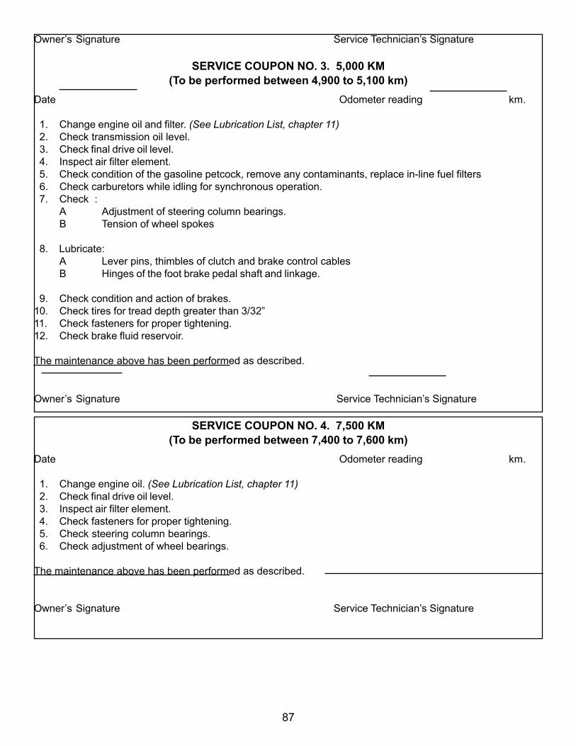
87
Owner’s Signature Service Technician’s Signature
SERVICE COUPON NO. 3. 5,000 KM(To be performed between 4,900 to 5,100 km)
Date Odometer reading km.
1. Change engine oil and filter. (See Lubrication List, chapter 11) 2. Check transmission oil level. 3. Check final drive oil level. 4. Inspect air filter element. 5. Check condition of the gasoline petcock, remove any contaminants, replace in-line fuel filters 6. Check carburetors while idling for synchronous operation. 7. Check :
A Adjustment of steering column bearings.B Tension of wheel spokes
8. Lubricate:A Lever pins, thimbles of clutch and brake control cablesB Hinges of the foot brake pedal shaft and linkage.
9. Check condition and action of brakes.10. Check tires for tread depth greater than 3/32”11. Check fasteners for proper tightening.12. Check brake fluid reservoir.
The maintenance above has been performed as described.
Owner’s Signature Service Technician’s Signature
SERVICE COUPON NO. 4. 7,500 KM(To be performed between 7,400 to 7,600 km)
Date Odometer reading km.
1. Change engine oil. (See Lubrication List, chapter 11) 2. Check final drive oil level. 3. Inspect air filter element. 4. Check fasteners for proper tightening. 5. Check steering column bearings. 6. Check adjustment of wheel bearings.
The maintenance above has been performed as described.
Owner’s Signature Service Technician’s Signature
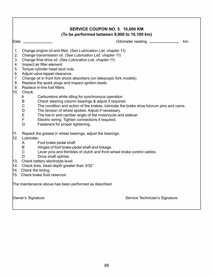
88
SERVICE COUPON NO. 5. 10,000 KM(To be performed between 9,900 to 10,100 km)
Date Odometer reading km.
1. Change engine oil and filter. (See Lubrication List, chapter 11) 2. Change transmission oil. (See Lubrication List, chapter 11) 3. Change final drive oil. (See Lubrication List, chapter 11) 4. Inspect air filter element. 5. Torque cylinder head stud nuts. 6. Adjust valve tappet clearance. 7. Change oil in front fork shock absorbers (on telescopic fork models) 8. Replace the spark plugs and inspect ignition leads. 9. Replace in-line fuel filters.10. Check:
A Carburetors while idling for synchronous operationB Check steering column bearings & adjust if required.C The condition and action of the brakes, lubricate the brake shoe fulcrum pins and cams.D The tension of wheel spokes. Adjust if necessary.E The toe-in and camber angle of the motorcycle and sidecar.F Electric wiring. Tighten connections if required.G Fasteners for proper tightening.
11. Repack the grease in wheel bearings, adjust the bearings.12. Lubricate:
A Foot brake pedal shaftB Hinges of foot brake pedal shaft and linkage.C Lever pins and thimbles of clutch and front wheel brake control cables.D Drive shaft splines
13. Check battery electrolyte level.14. Check tires, tread depth greater than 3/32”14. Check the timing.15. Check brake fluid reservoir.
The maintenance above has been performed as described.
Owner’s Signature Service Technician’s Signature
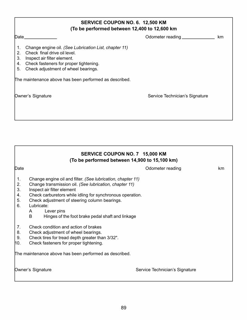
89
SERVICE COUPON NO. 6. 12,500 KM(To be performed between 12,400 to 12,600 km
Date Odometer reading km
1. Change engine oil. (See Lubrication List, chapter 11) 2. Check final drive oil level. 3. Inspect air filter element. 4. Check fasteners for proper tightening. 5. Check adjustment of wheel bearings.
The maintenance above has been performed as described.
Owner’s Signature Service Technician’s Signature
SERVICE COUPON NO. 7 15,000 KM(To be performed between 14,900 to 15,100 km)
Date Odometer reading km
1. Change engine oil and filter. (See lubrication, chapter 11) 2. Change transmission oil. (See lubrication, chapter 11) 3. Inspect air filter element 4. Check carburetors while idling for synchronous operation. 5. Check adjustment of steering column bearings. 6. Lubricate:
A Lever pinsB Hinges of the foot brake pedal shaft and linkage
7. Check condition and action of brakes 8. Check adjustment of wheel bearings. 9. Check tires for tread depth greater than 3/32".10. Check fasteners for proper tightening.
The maintenance above has been performed as described.
Owner’s Signature Service Technician’s Signature
90
SERVICE COUPON NO. 8. 17,500 KM(To be carried out within 17,400 to 17,600 km
Date Odometer reading km
1. Clean the air filter, . 2. Change oil in the engine and transmission. (See Lubrication List, chapter 11) 3. Check condition of the gasoline petcock, remove any contaminants, clean and blow out.
4. Check carburetors while idling for synchronous operation. 5. Check final drive gear oil level. (See Lubrication List, chapter 11) 6. Lubricate foot brake pedal shaft. 7. Check fasteners for proper tightening. 8. Adjust steering column bearings. 9. Check battery electrolyte level and fluid level.10. Check air gap in electronic ignition between pickup and rotor (0.010 in).
The maintenance above has been performed as described.
Owner’s Signature Service Technician’s Signature

91
SERVICE COUPON NO. 9. 20,000 KM(To be performed between 19,900 to 20,100 km)
Date Odometer reading km.
1. Change engine oil and filter. (See Lubrication List, chapter 11) 2. Change transmission oil. (See Lubrication List, chapter 11) 3. Change final drive oil. (See Lubrication List, chapter 11) 4. Inspect air filter element. 5. Torque cylinder head stud nuts. 6. Adjust valve tappet clearance. 7. Change oil in front fork shock absorbers (on telescopic fork models) 8. Replace the spark plugs and inspect ignition leads. 9. Replace in-line fuel filters.10. Check:
A Carburetors while idling for synchronous operationB Check steering column bearings & adjust if required.C The condition and action of the brakes, lubricate the brake shoe fulcrum pins and cams.D The tension of wheel spokes. Adjust if necessary.E The toe-in and camber angle of the motorcycle and sidecar.F Electric wiring. Tighten connections if required.G Fasteners for proper tightening.
11. Repack the grease in wheel bearings, adjust the bearings.12. Lubricate:
A Foot brake pedal shaftB Hinges of foot brake pedal shaft and linkage.C Lever pins and thimbles of clutch and front wheel brake control cables.D Drive shaft splines
13. Check battery electrolyte level.14. Check tires, tread depth greater than 3/32”14. Check the timing.
The maintenance above has been performed as described.
Owner’s Signature Service Technician’s Signature
The maintenance above has been performed as described.

92
SERVICE COUPON NO. 10. 22,500 KM(To be performed between 22,400 to 22,600 km
Date Odometer reading km
1. Change engine oil. (See Lubrication List, chapter 11) 2. Check final drive oil level. 3. Inspect air filter element. 4. Check fasteners for proper tightening. 5. Check steering column bearings. 6. Check adjustment of wheel bearings.
The maintenance above has been performed as described.
Owner’s Signature Service Technician’s Signature
SERVICE COUPON NO. 11. 25,000 KM(To be performed between 24,900 to 25,100 km)
Date Odometer reading km.
1. Change engine oil and filter. (See Lubrication List, chapter 11) 2. Change transmission oil. (See Lubrication List, chapter 11) 3. Inspect air filter element. 4. Check carburetors while idling for synchronous operation. 5. Check:
A Adjustment of steering column bearings.B Tension of wheel spokesC Toe-in and camber of the motorcycle and sidecar
6. Lubricate:A Lever pinsB Foot brake pedal shaftC Hinges of the foot brake pedal shaft and linkage.
7. Check condition and action of brakes 8. Check tires for tread depth greater than 3/32” 9. Check fasteners for proper tightening.
The maintenance above has been performed as described.
Owner’s Signature Service Technician’s Signature

93
SERVICE COUPON NO 12. 27,500 KM(To be performed between 27,400 to 27,600 km)
Date Odometer reading km
1. Change engine oil. (See Lubrication List, chapter 11) 2. Check final drive oil level. 3. Inspect air filter element. 4. Check fasteners for proper tightening. 5. Check steering column bearings. 6. Check adjustment of wheel bearings.
The maintenance above has been performed as described.
Owner’s Signature Service Technician’s Signature

94
SERVICE COUPON NO. 13. 30,000 KM(To be performed between 29,900 to 30,100 km)
Date Odometer reading km.
1. Change engine oil and filter. (See Lubrication List, chapter 11) 2. Change transmission oil. (See Lubrication List, chapter 11) 3. Change final drive oil. (See Lubrication List, chapter 11) 4. Inspect air filter element. 5. Torque cylinder head stud nuts. 6. Adjust valve tappet clearance. 7. Change oil in front fork shock absorbers (on telescopic fork models) 8. Replace the spark plugs and inspect ignition leads. 9. Replace in-line fuel filters.10. Check:
A Carburetors while idling for synchronous operationB Check steering column bearings & adjust if required.C The condition and action of the brakes, lubricate the brake shoe fulcrum pins and cams.D The tension of wheel spokes. Adjust if necessary.E The toe-in and camber angle of the motorcycle and sidecar.F Electric wiring. Tighten connections if required.G Fasteners for proper tightening.
11. Repack the grease in wheel bearings, adjust the bearings.12. Lubricate:
A Foot brake pedal shaftB Hinges of foot brake pedal shaft and linkage.C Lever pins and thimbles of clutch and front wheel brake control cables.D Drive shaft splines
13. Check battery electrolyte level.14. Check tires, tread depth greater than 3/32”15. Check the timing.
The maintenance above has been performed as described.
Owner’s Signature Service Technician’s Signature

95
NEW ADDRESS FORM
If you move, please fill out this form and mail to the address below. This will insure that you con-tinue to receive all correspondence from Irbit Motorworks of America.
VEHICLE IDENTIFICATION NUMBER
OWNER’S NAME _____________________________________________
OLD ADDRESS ______________________________ APT. NO. _______
CITY ________________ STATE ____________ ZIP CODE _________
MY NEW ADDRESS IS:
NEW ADDRESS ____________________________ APT. NO. ________
CITY _______________ STATE _____________ ZIP CODE _________
Send this form to:Irbit Motorworks of America,
15411 NE 95th St. Redmond, WA 98052
or fax to:(425) 696 - 0834

96
NEW OWNER FORM
If you purchase a Ural Motorcycle from somebody other than a dealer, please fill out this form andmail to the address below. This will insure that you receive all correspondence from Irbit Motor-works of America
VEHICLE IDENTIFICATION NUMBER
NEW OWNER’S NAME _____________________________________________
ADDRESS ______________________________ APT. NO. _______
CITY ________________ STATE ____________ ZIP CODE _________
DATE OF SALE ________________ MO / DAY / YEAR
Purchased From ___________________________________________________
City _____________________State ____________ Zip Code _______________
Send this form to: Irbit Motorworks of America,
15411 NE 95th St Redmond, WA 98052
or fax to:(425) 696 - 0834

97
URAL - STARTING & RUNNING TIPSStarting the Engine
1. Open carburetor enricheners on both carburetors (pull lever out) if temperature is below 50 degrees.
2. Make sure fuel petcock is open “ON” or prime “PRI”
3. Ignition “RUN,” “KILL,” switch set to “RUN” (down), gearbox in “NEUTRAL”.
4. Push starter button until engine fires, OR…
5. With foot on kick-starter lever, push foot down swiftly and hard open the throttle grip slightly. Repeat until engine fires (usually 2 or 3 kicks). Turn OFF enricheners.
6. Let the engine warm up for 1-3 minutes, depending on the temperature.
7. After the engine has warmed up, operate the motorcycle under moderate loads and speeds forseveral miles until the oil has circulated well and the engine and gearbox are functioning smoothly.
Trouble ShootingIf engine does not start with above method, the problem(s) may be one or more of the following:
1. Engine is “flooded,” i.e.; the spark plugs have been “fouled” by too much throttle ( and fuel ) and willnot spark.Correction: Flooding is corrected by removing the spark plugs and drying them.
2. Too little fuel is getting to the engine due to low fuel in tank and/or plugged fuel lines or fuel petcock.Correction: Clogged fuel lines or filter are corrected by blowing through fuel lines from carburetor end toremove any debris from lines. Fuel petcock filter can be cleaned by removing and cleaning.
3. Little or no spark is available to the engine due to a low battery, (dim headlight), or loose ignitionwires.Correction: Dead battery is corrected by charging battery, loose or broken ignition wires are corrected byreplacing broken wire(s) orby reconnecting wires at either the spark plug cap, the ignition module, or at the
ignition coil under the front cover of the engine.*4. Not enough compression in the cylinders due to excessive wear or incorrect adjustment of valve(s).
* item 4 above requires the attention of a qualified mechanic at your URAL dealer.
***WARNING!...Reverse Gear Damage... WARNING!***
Attempting to engage reverse gear while the motorcycle is moving may cause SEVERE damage to thegearbox and will void the warranty. Engage the reverse gear only when the motorcycle is completelystopped and is either in 1st gear or neutral.

98
Pre-Trip Check List
1. Check all lights and the horn for proper operation.2. Check the brake and clutch levers and/or pedals.3. Make sure all wheels and the final drive assemblies are securely fastened .4. Check the carburetor flanges and air filter ducts for integrity and proper alignment.5. Check the tire tread depth - should be greater than 1/8 inch.6. Check the sidecar attachment mounts – all mounts should be securely tightened.
Gasoline level in the fully filled tank should be 10 - 15 mm / ½ - ¾ in. below the lower edge of thetank filler. Do not overfill the tank.
See that the oil level in the engine crankcase is not higher than the top and not lower than thebottom marks on the dipstick with the filler plug undone.(See chapter 4 Lubrication System)

99
Available through Mike [email protected]
www.molotovmotors.com
Here Are Some Helpful Publications To Help You With YourNew Ural
Learning to Ride The Ural With Sidecar AccessoryAvailable through the Whitehorse Press
www.whitehorsepress.com
Weav’s Useful Information and Technical Guide to Antique Russian Motorcycles and Sidecars