Threading the Sewing Machine Place the Spool of Thread on the Spool Pin.
IMPORTANT NOTEIMPORTANT NOTEIMPORTANT NOTEIMPORTANT NOTE
BID DOCUMENT HAS BEEN DISPLAYED BELOW TO
UNDERSTAND THE REQUIREMENT ONLY. PARTIES
INTERESTED TO PARTICIPATE AGAINST THIS TENDER
SHALL HAVE TO PURCHASE THE TENDER DOCUMENT
FROM ANY OF OIL’S DESIGNATED OFFICES MENTIONED IN
THE TENDER NOTIFICATION. PROOF OF PURCHASE OF
TENDER DOCUMENT MUST BE SUBMITTED ALONG WITH
THE OFFER FAILING WHICH OFFERS SHALL BE TREATED
AS UNSOLICITED.

OIL INDIA LIMITED ( A Govt. of India Enterprise )
4, India Exchange Place, Kolkata – 700 001.
OIL INDIA LIMITED (OIL) invites sealed tenders for supply, installation / commissioning of the following items :- Srl. No.
Tender No. (Bid Closing Date)
Materials Description Single Order Value in ( Rs. Lakhs)
Annual Turnover
in (Rs. Lakhs)
1.
KID5568P10/03 (11-12-09)
Auto Evacuation System for LPG Cylinder – 1 No.
12
24
2. KID5565P10/03 (11-12-09)
Acoustic Enclosure for 30 KVA Genset -10 Nos.
32.50 65
3. KID5567P10/03 (11-12-09)
Acoustic Enclosure for 15 KVA Genset -5 Nos.
14 28
4. KID5645P10/08 (11.12.09)
FLP Electric Motor Driven Screw Pump – 2 Nos.
36 72
5. KID5599P10/02 (11-12-09)
Flow Metering System for LPG Tankers – 2 items.
37 74
2.0 Bid documents (Non transferable) can be purchased from 04.11.2009 till one day prior to the respective Bid Closing Dates on payment of tender fee of Rs. 1000.00 each through Crossed Demand Draft in favour of M/s. Oil India Limited (excepting for PSUs and SSI units registered with NSIC/Directorate of Industries for the item) from (A) Head (Calcutta Branch), Oil India Limited, 4,India Exchange Place, Kolkata - 700001 (B) Head Materials, Oil India Limited, P.O. Duliajan, Assam - 786602 (C) Sr. Adviser (Contract & Purchase), Oil India Limited, Plot No. 19, Sector-16A, Noida – 201301 (D) Sr. Materials Manager (Pipeline), Oil India Limited, P.O: Udayan Vihar, Guwahati - 781171.
3.0 To be eligible for issue of tender documents, the applicant must meet the following qualifying criteria (documentary evidence to be provided) :
(i) Successful execution of a single order of value not less than the amount shown above for supply of similar items during last five years. (ii) Annual turnover of the firm in any of the last three financial years or current financial year should be more than the amount shown above. 4.0 Bidders may visit OIL’s website www.oil-india.com for further details on the above tenders.
CORRIGENDUM 1. The Bid Closing Date against Tender No. KID4216P10/03 dt. 13-07-09 for Fire Tube for Emulsion Treaters – 11 Nos. has been extended to 13.11.2009 (14.00 Hrs.)
* * *

OIL INDIA LIMITED(A Govt. Of India Enterprise) Tel :033 2230 1657, 16584, India Exchange Place, Fax :91 33 2230 2596Kolkata-700001 E-mail :[email protected] No. & Date :KID5599P10/02 26.10.2009
Bid Security Amount : INR 185,000.00 OR USD 0.00
Bidding Type :
(or equivalent Amount in any currency)
Single Bid (Composite Bid)
Bid Closing OnBid Opening On
Performance Guarantee
::
:
11.12.2009 at 14:00 hrs. (IST)11.12.2009 at 14:00 hrs. (IST)
Applicable
OIL INDIA LIMITED invites Limited tenders for items detailed below:
Item No./Mat. Code
Material Description Quantity UOM
100C000210
FLOW METERING SYSTEM FOR LPG TANKERS
Flow Metering & Semi-Automatic Control System for Filling of LPG &Condensate in Tankers from LPG Filling Plant detiled description is enclosedin Annexure - A.
3 NO
200C000210
SAME AS ITEM NO.10. 1 NO
INSTALLATION & COMMISSIONING10 INSTALLATION & COMMISSIONING 1 AU
Special Notes : 1. I) The bidder may inspect the site at their own cost to access the requirement of materialrequired to carry out the up-gradation project. Any item not spelt out but required for completionof the project is to be supplied. The bidder must specify the same in their offer.
II) The material to be supplied must be new and from original manufacturer with serial numberand date of manufacture.
III) Equipment should be tested thoroughly before dispatch at the supplier's yard.
IV) The supplied material must be warranted against manufacturing defect for a period of at least(one) 1 year after installation of the same at site. In case of any defect during the warrantyperiod, the supplier shall arrange to repair/replace as applicable. The necessary spares requiredfor repairing the equipment should be provided by the supplier at their own cost.
V) The up gradation will be deemed to be commissioned only after installation, commissioningand continuous running of the system for a minimum period of 72 hours at fully loaded conditionduring the plant operation.
VI) Training of Instrumentation Engineers: The supplier must train the Instrumentation engineersto carry out maintenance activities of the upgraded system. Three sets of maintenance manualin CD and hard copy form must be supplied during commissioning. The bidder has to agree toextensively train two Instrumentation engineers in two batches at their works free of cost. The
Page : 1 / 3

training at the works must cover the software, hardware and simulation of the system.
VII) The bidder must furnish a detailed list of similar up gradation jobs carried out in otherOil/Gas/Petroleum Organizations in India/Abroad.
VIII) Bidder will have to undertake the guarantee for all such items supplied by them as a part ofthe up gradation project which is either bought out or imported from some other party. Bidder willhave to produce documentary evidence for the same along with the supply of materials.
IX) Bidder will have to ensure that all the open (items which are not proprietary of the bidder)hardware & software packages supplied by them as a part of the up-gradation project is of latestrevision & version available in the market. Bidder will have to produce documentary evidence forthe same along with the supply of materials.
X) Receipt, storage of material, transportation of the same to the work spot as required shall beunder the scope of the Bidder.
XI) Installation, testing & commissioning of the whole up-gradation job as well as functionaltesting of the complete system will have to be carried out by the Bidder to the full satisfaction ofOIL engineers at site which will form the basis of site acceptance test (SAT). Installation &commissioning charges, if any, must be quoted separately clearly indicating the applicableservice taxes.
XII) Inspection of the materials will be carried out by OIL engineers at supplier's factory prior todispatch of materials to site. The complete FAT of the whole up-gradation package will have todemonstrated to OIL engineers during factory inspection & the same will have to be approved byOIL before the materials are dispatched to site.
XIII) The Bidder should depute adequate number of competent & qualified sitepersonnel/workers at site to ensure smooth installation & commissioning of the new system.
XIV) The bidder will have to provide the item wise break-up of prices in the BOM to be submittedto OIL for evaluation.
XV) 230V AC supply for the up-gradation job will be provided by OIL near the tanker fillingpoints. All the necessary cablings from these points to the respective instruments will be in thebidder's scope including the supply of cables. There is no control room at site,so for requirementof any power other then 230V AC like 24V DC power supply etc will have to be arranged by thebidder. Mounting of the same will also have to be carried out by the bidder at respective tankerfilling points only.
XVI) Documentation: Bidder will have to supply 6 sets of as built drawings, instruction manuals &operation & maintenance manuals along with the delivery of the items. License copy of all thenecessary software's to be supplied as a part of the up-gradation project should be provided toOIL in CD format for our future use.
XVII) Warranty: The Bidder should guarantee the trouble free performance of the suppliedsystems & work executed for a period of 12 months from the date of complete system beingcommissioned & handed over to OIL. Incase of any defect or nonperformance of the system or acomponent during this twelve months guarantee period the same will have to be replaced free ofcost. Any damage or defect that may arise or lie undiscovered at the time of completion of jobshould be rectified or replaced by the Bidder at their own cost.
XVIII) All the items/components that will be supplied for the up-gradation project should beapproved by CCOE, Certified by CMRI & documentary evidence of the same needs to beprovided along with the bid. The mass flow meters to be supplied must have weight & measuresapproval for custody transfer & documentary evidence of the same needs to be provided along
Page : 2 / 3

with the bid.
XIX) Bidder will have to submit the detail interconnection diagram between all the items to besupplied for the project along with the detail description of the working philosophy for the entiresystem.
XX)Bidder will have to provide a complete list of two years mandatory spares for the entiresystem along with unit price of each item.
2. (I) BID REJECTION CRITERIA (BRC)
a. The bidders must produce at least 10(ten) examples of similar jobs carried out in otherOil/Gas/Petroleum Organizations in India/Abroad.
b. The Bid should be submitted in a tabular form stating offered specification vs NITspecifications against each point. Bid in any other form will not be acceptable. The offeredspecification must be substantiated by the bidder's published technical catalog and/or website.
c. If the technical specifications of the offer are not as per OIL's requirement stipulated in the biddocument, the offer will be rejected.
d. In case the bidder do not comply with the points of special conditions, installation andcommissioning, warranty, Training, after sales service etc. as stipulated, the offer will berejected.
e. Bidder must indicate the year of launch of the offered models. Obsolete products will not beconsidered for evaluation. The bidder must state an undertaking that they will be able to provideessential spares necessary for a minimum period of 10 years.
f. The bidder must provide license of any software that may be supplied along with theirequipment.
2.(II) BID EVALUATION CRITERIA (BEC):The bids conforming to the specifications, terms and conditions stipulated in the enquiry andconsidered to be responsive after subjecting to the Bid Rejection Criteria will be considered forfurther evaluation as per the Bid Evaluation Criteria given below:
A. TECHNICAL:All materials as indicated in the material description of the enquiry should be offered. If any ofthe items are not offered by the bidders, the offer will not be considered for evaluation.
3. Payment : 70% payment against supply of material after deducting liquidated damages, if anyand balance 30% payment on successful installation and commissioning of the material at site.(Refer relevent para of attached Annexure - II).
Page : 3 / 3

ANNEXURE A
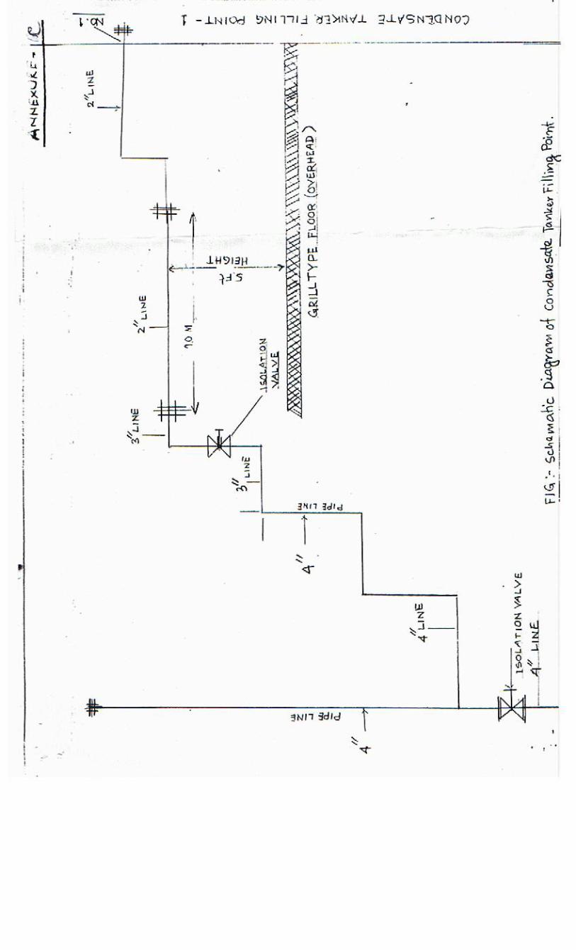
ITEM DESCRIPTION AND DRAWINGS FOR TENDER KID5599P10/02 DATED 26.10.09 FOR BOTH ITEMS NO 10 & 20 OF THE TENDER Flow Metering & Semi-Automatic Control System for Filling of LPG & Condensate in Tankers from LPG Filling Plant Preamble: M/S Oil India Limited is in the business of selling LPG & Condensate produced from its LPG recovery plant to different customers through road tankers. The capacity of the tankers are in the range of 6.8MT to 18MT. The filling operation of LPG in tankers is at present carried out through a system comprising of Positive displacement meters & Batch Controllers with the help of a Mechanical type of Weigh-Bridge for knowing the tare weight & the gross weight of the tankers. The filling operation of Condensate in tankers is carried out through manual process of verifying the tanker level by dip stick & checking the gross & tare weight in a mechanical weigh bridge. We at present have three LPG loading points & one number of Condensate loading point. Schematic drawing of the present filling arrangement is enclosed as Annexure-B & Annexure-C.
1. General Requirements:
Through the subject tender we intend to carry out the following minimum changes in our present LPG & Condensate filling systems:
1. To replace the existing PD (Positive displacement meters) with Mass flow meters in the LPG liquid lines & new meter in Condensate line along with new strainers, gas separators, RTD, Pressure transmitters etc for accurately determining the total mass weight of product filled in a tanker.
2. To introduce Mass flow meters in the LPG vapor return line to account for the total mass of LPG vapor.
3. To replace the old batch controllers in LPG loading terminals with new ones & a complete new batch controller system for Condensate loading along with all the accessories associated with operation of the batch controller (i.e. all inputs & outputs to & from batch controller) like earthing relay, digital control valve, loading arm position sensor etc.
4. ESD Push button system for tackling emergency & for complete isolation.
1

With the above minimum changes we intend to achieve a semi-automatic terminal automation system where the operator will only enter manually the preset quantity of product in the batch controller to be filled in the tankers as per the invoice available with the truck driver. The system comprising of above minimum equipments & other additional components as per design will ensure that once the operator has entered the preset value, the filling & verification of the product in the tanker will be completely automatic. The system should be able to provide a printout of the total quantity filled in the tanker to the operator. The system should also be able to completely shutoff & isolate the filling facilities in case of depressing of ESD push button by the operators. With mass flow meters in both LPG filling & LPG vapor return line, the batch controller should be configured to measures the dispensed LPG quantity and Vapor quantity using the flow Measuring Meter i.e. Mass Flow Meter which are connected at both inlet of LPG flow & at Vapor recovery line .Batch controller will calculate Net quantity and control the primary LPG flow control valve according to the net delivered quantity.
Net quantity = Loaded Quantity – Vapor Quantity for LPG loading Net quantity = Loaded quantity measured by mass flow meter for Condensate
loading As net quantity is invoice able, the weighbridge requirement can be eliminated for knowing the gross weight of the tankers. However M/S OIL for the time being will keep on using the existing Mechanical type Weigh Bridges for knowing the actual tare weight of incoming LPG & Condensate tankers & based on this tare weight the filling invoice will be prepared.
2. Desired working philosophy of the system: The batch controller will receive flow input data from the mass flow meters in the LPG/Condensate lines & the LPG vapor return lines. The batch controller will also receive the RTD, Earthing relay input for ensuring proper Earthing of tankers, Loading arm position sensor input & Pressure transmitter inputs from the product filling line. The preset quantity to be loaded in the tankers will be entered by the operator in the batch controller & based on the entered data & the actual flow measured by the mass flow meters, the batch controller will control the digital control valve for actually transferring the invoiced mass quantity of product in the tankers. There should be remote interaction terminal at each tanker filling point. The batch controller should be connected to a printer for printing the total quantity of product transferred to the tankers. There should be an ESD push button in each tanker filling point for immediate shutdown of the tanker filling operations in case of any emergency. The new system should have provision for integrating it with other accessories to function as a fully automatic terminal automation system in future. However bidder can suggest systems with better capabilities but should meet our above described requirements.
2

3. Tentative bill of materials:
Sr. No. Description Make UOM Quantity
Field Instruments
1 Gas separator LC/Flashpoint/Reputed Nos. 3
2 MFM with transmitter (3 FOR LPG + 1 FOR CONDENSATE)
Micromotion Nos. 4
3 MFM with transmitter for vapour return (3 FOR LPG)
Micromotion Nos. 3
4 Piston operated DCV Reputed Nos. 4
5 Isolation ball valve on/off Audco /Virgo /reputed Nos. As per system design
8 Pressure Guage Waree/wika/reputed Nos. As per system design
9 RTD with Thermowell Altop / waree Nos. 4
10 Pressure Transmitter Emerson / Yokogawa/reputed
Nos. 4
11 Batch Controller single channel DANLOAD/reputed Nos. 4
15 Remote interaction terminal
Baliga / Flexpro / Reputed Nos.
4
16 Earthing relay with earthing clamp and cable Reputed Nos. 4
17 Emergency Shut Down push button
Baliga / Flexpro / Reputed Nos.
4
18 Loading arm position sensors – Our loading arms are M/S Wood-field make
Reputed Nos.
4
18 Card reader as optional item
reputed Nos.
4
19 Printer
reputed Nos.
As per system design
Miscellaneous items
1 Cables, JB's, Glands, Trays etc. LOT 1
2 Erection hardware, structurals, etc. LOT 1
3 Mandataory spares as per spares philosophy AST LOT 1
Services
1 Design, Engineering & project management AST 1
2 Documentation AST 1
3 Erection Commissioning & SAT AST 1
4 TPI, W&M certification etc AST 1
5 Training & hand holding AST 1
The above bill of material is tentative only & bidder must quote for all the items that will be required to realize the system design as described under the general requirements & desired working philosophy of the system.
3

4. Specifications for the main components of the flow metering system:
1. Mass flow meters for LPG – Quantity 03 nos Application: Custody transfer, Batch applications
Specifications for SENSOR Measuring principle: Coriolis (Should be able to measure Mass, Density and Temperature Directly) Tube geometry: Curved, Twin 'U' tube Type of tube: Seam less (from end to end) Maximum tube pressure: Should be as per flow tube rating Mounting: Directly on pipe. Tube material: SS 316L Process fluid: LPG Process fluid characteristics: Water content : Nil Wax content : Nil Asphaltene content : Nil Specific Gravity : 0.538 to 0.6 Pour point : Data not available Viscosity : 0.9cps Operating pressure : 12 - 20 Kg/cm2 Operating temperature: 30-50 DEGREE C Density : 0.538 to 0.6 Maximum pressure : 25 Kg/cm2 Maximum Flow rate : 40 MTPH (Metric Tonnes per hour) Nominal Flow rate : 34 MTPH (Metric Tonnes per hour) Minimum Flow rate : 0 MTPH (Metric Tonnes per hour) Process pipe line characteristics: Size: 3 inch for MOC: CS (Carbon steel) Vibration: Minimum Mass Flow accuracy : better than ± 0.2% of rate Mass flow repeatability : ± 0.05% of rate Density accuracy : ± 0.0005 gm/cc or better Density repeatability : ± 0.0002 gm/cc Temperature accuracy : ± 10 DEGREE C Temperature repeatability : ± 0.20 DEGREE C Pressure drop at maximum flow rate: not more than 0.5 Kg/cm2
4

Flow tube rating : Should be as per flow meter sizing Housing rating : To be designed to suit process fluid characteristics. Material of construction : SS316 MOC of Housing : SS304 Sensor size : 2 inch preferably Hazardous Area classification: Suitable to Zone 1, Group IIA/ IIB Approval : Should be approved by DGMS /CCOE For operating in Zone 1, Group IIA/ IIB area. Electrical jacketing (if required):To be provided to maintain the sensor at room temperature Lightning & surge protection: To be suitably provided Process End connection : Flanged (2 Inch ANSI 300 Class RF Flanged with 1 Pair metal Gasket, size-50mm) , if required 3inch to 2inch reducer/expander to be provided for hooking up the meter in our existing pipeline. Flange to Flange distance : Preferably should be within 500mm. Height of housing from the : Preferably should be within Centre of the sensor tube 600mm. Specifications for Transmitter Technology : Integral type, Electronic, (Remote type) microprocessor based/Coriolis based system. Outputs : 2 Nos of 4-20 mA (Independent) - should be user configurable . For either mass flow rate, totalized mass flow or density. 1 No RS485 Modbus signal 3 Nos Discrete Outputs configurable for HI/LOW alarm, error diagnostics, flow direction etc. 2 nos. discrete digital inputs configurable for transmitter zeroing, totaliser reset etc. 1 frequency or pulse output, 0-10000HZ, configurable for mass, totalized mass, volume or totalized volume outputs for integration purpose. 1 No RS232 (For Local Printer) Digital Protocol : HART Output parameters : Volumetric flow rate Mass Flow rate
5

Density Temperature Totalized flow with reset Option Display unit : Back lit LCD with Keypad membrane switch Of pushbuttons with tactile Feedback. Display should have minimum 4 lines to display instateneous flow rate,density,temperature,totalized flow((mass flow rate,density(or temperature) with selectable engineering units & totalized flow simultaneously). Type of display : Interactive Display features : View all process variables View and acknowledge alarms Self diagnostic features: empty pipe detection, slug flow detection, temperature limit detection, auto zero event history. Enclosure : NEMA 4 (As the Transmitter is required to be installed in the field near the sensor, it should be approved by DGMS for operating in Zone 1, Group IIA/IIB area) Material of construction : Cast Aluminium Housing Power supply : 24 V DC (At site only 230V AC will be available) Electrical connection : ½”NPT Male for both power & Output Signal cables. Cable : Interconnecting cable between transmitter & sensor to be provided. length should be 200metres. Ambient temperature limits : 0 - 50 Degree C Lightning & Surge protection : To be suitably provided Additional feature : To remediate gas bubbles (if any) as they pass through the sensor Enclosure Mounting : The enclosure which contains the Transmitter/Display unit will have to be mounted in the field. Necessary arrangements along with mounting brackets have to be supplied. Preferably the enclosure should come with arrangements for 2 inch pipe mounting.
6

Wet calibration: Wet calibration will have to be carried out at NABL approved flow calibration laboratory, preferably FLUID CONTROL RESEARCH INSTITUTE, PALAKKAD & necessary certificates will have to be provided along with the materials. Hydro testing: Hydro testing of the offered sensor to be carried out at flow tube rating pressure & necessary certificates will have to be provided along with the materials. 2. Mass flow meters for Condensate measurement: Application: Custody transfer, Batch applications Specifications for SENSOR Measuring principle: Coriolis (Should be able to measure Mass, Density and Temperature Directly) Tube geometry: Curved, Twin 'U' tube Type of tube: Seam less (from end to end) Maximum tube pressure: Should be as per flow tube rating Mounting: Directly on pipe. Tube material: SS 316L Process fluid: Natural gas condensate liquid Process fluid characteristics: Water content : Nil Wax content : Nil Asphaltene content : Nil Specific Gravity : 0.6770 at 60DEGREE F Pour point : -33 DEGREE C Viscosity : Not available Operating pressure : 9.5 - 14 Kg/cm2 Operating temperature: 30-50 DEGREE C Density : 0.67 to 0.68 at 15 DEGREE C Maximum pressure : 15 Kg/cm2 Operating pressure : 12 Kg/cm2 Maximum Flow rate : 40 MTPH (Metric Tonnes per hour) Nominal Flow rate : 34 MTPH (Metric Tonnes per hour) Minimum Flow rate : 0 MTPH (Metric Tonnes per hour) Process pipe line characteristics: Size: 2 inch MOC: CS (Carbon steel) Vibration: Minimum
7

Mass Flow accuracy : better than ± 0.2% of rate Mass flow repeatability : ± 0.05% of rate Density accuracy : ± 0.0005 gm/cc or better Density repeatability : ± 0.0002 gm/cc Temperature accuracy : ± 10 DEGREE C Temperature repeatability : ± 0.20 DEGREE C Pressure drop at maximum flow rate: not more than 0.5 Kg/cm2 Flow tube rating : 100 Kg/Cm2 (minimum) Housing rating : To be designed to suit process fluid characteristics. Material of construction : SS316 MOC of Housing : SS304 Sensor size : 2 inch Hazardous Area classification: Suitable to Zone 1, Group IIA/ IIB Approval : Should be approved by DGMS For operating in Zone 1, Group IIA/ IIB area. Electrical jacketing (if required):To be provided to maintain the sensor at room temperature Lightning & surge protection: To be suitably provided Process End connection : Flanged (2 Inch ANSI 300 Class RF Flanged with 1 Pair metal Gasket, size-50mm) Flange to Flange distance : Preferably should be within 500mm. Height of housing from the : Preferably should be within Centre of the sensor tube 600mm. Specifications for Transmitter Technology : Integral type, Electronic, (Remote type) microprocessor based/Coriolis based system. Outputs : 2 Nos of 4-20 mA (Independent) - should be user configurable . For either mass flow rate, totalized mass flow or density. 1 No RS485 Modbus signal 3 Nos Discrete Outputs configurable for HI/LOW alarm, error diagnostics, flow direction etc. 2 nos. discrete digital inputs configurable for transmitter zeroing, totaliser reset etc.
8

1 frequency or pulse output, 0-10000HZ, configurable for mass, totalized mass, volume or totalized volume outputs for integration purpose. 1 No RS232 (For Local Printer) Digital Protocol : HART Output parameters : Volumetric flow rate Mass Flow rate Density Temperature Totalized flow with reset Option Display unit : Back lit LCD with Keypad membrane switch Of pushbuttons with tactile Feedback. Display should have minimum 4 lines to display instateneous flow rate,density,temperature,totalized flow((mass flow rate,density(or temperature) with selectable engineering units & totalized flow simultaneously). Type of display : Interactive Display features : View all process variables View and acknowledge alarms Self diagnostic features: empty pipe detection, slug flow detection, temperature limit detection, auto zero event history. Enclosure : NEMA 4 (As the Transmitter is required to be installed in the field near the sensor, it should be approved by DGMS for operating in Zone 1, Group IIA/IIB area) Material of construction : Cast Aluminium Housing Power supply : 24 V DC (At site only 230V AC will be available) Electrical connection : ½”NPT Male for both power & Signal cables. Cable : Interconnecting cable between transmitter & sensor to be provided. length should be 200metres.
9

Ambient temperature limits : 0 - 50 Degree C Lightning & Surge protection: To be suitably provided Additional feature : To remediate gas bubbles (if any) as they pass through the sensor Enclosure Mounting : The enclosure which contains the Transmitter/Display unit will have to be mounted in the field. Necessary arrangements along with mounting brackets have to be supplied. Preferably the enclosure should come with arrangements for 2 inch pipe mounting. Wet calibration: Wet calibration will have to be carried out at NABL approved flow calibration laboratory preferably, FLUID CONTROL RESEARCH INSTITUTE, PALAKKAD & necessary certificates will have to be provided along with the materials. Hydro testing: Hydro testing of the offered sensor to be carried out at flow tube rating pressure & necessary certificates will have to be provided along with the materials. 3. Mass flow meter for LPG vapor lines Specification for these meters is same as that of point no.1 for mass flow meter for LPG liquid except the following: Process: LPG vapor Line size: 2 inch Flow rates & Pressure: Cannot be specified accurately, but will be comparable to flow rates observed in other similar LPG tanker loading applications.
10

4. Batch Controller specifications: Specification for BATCH CONTROLLER
TYPE Micro processor based Single Channel MAKE MODEL NO
MOUNTING Field Mounted POWER SUPPLY 230V AC, 50 Hz @ 25VA INPUTS -Pulse input from Mass Flow Meter
-Start / Stop / Acknowledge digital input from RIT -Safety permissive inputs for interlock i.e. Earth, Arm interlock & Card reader
OUTPUTS -Digital output to SOV’s of Digital Control valve -Digital output to Red, Yellow and Green lamps on RIT
ALARMS -Interlock failure -Flow rate out of limits -Temperature failure meter -Unable to close valve meter -Communications failure
COMMUNICATION -Redundant RS 485 communication with extended MODBUS protocol -Multi dropping- 04 batch controllers are multi-dropped on same transmit & receive data lines (i.e. single loop)
DISPLAY & OTHER FEATURES -Alpha-numeric, back lit LCD display -Bar graph for percentage filling of current batch. -3 LED’ i. e. Alarm, Auto mode and Permissive power. -Dynamic user selectable data display -Text display for Preset qty, Loaded qty and Alarms. -Numeric keypad with Hall effect keys. -Self diagnostics Available for RAM, Keypad, Displays, Inputs, Outputs and Communication. -Memory capacity 32 K EPROM, 16 K RAM
FUNCTIONS -Indication & totalization -Volume calculations -Flow control -Batch control - 4 Points Meter factor linearization -Programmable ramp down for two stage opening / closing of Digital control valve -Executing local loading ( stores 500 batches for retrieval from LRCS when communication is established ) -Dynamic data display. -Security for program mode and Local / Remote mode selection.
CERTIFICATION -Ex-proof to zone 1, GR IIA & IIB, T6 -Weather proof to IP-65 CMRI, CCOE approval required.
11

5. Specifications for Earthing Relays:
SPECIFICATIONS FOR EARTHING RELAY
1 FUNCTION To Provide proper Earthing to tank truck and will send signal to associated controller to stop loading upon loss of earth connection.
2 CONNECTION TO TANK TRUCK
Ground ball or Crocodile Clip ( both options provided )
3 MOUNTING Field 4 POWER SUPPLY 230 VAC + / - 50Hz 5 POWER CONSUMPTION 10 W 6 SIGNAL INPUT Probe from body of earthed tank truck 7 OUTPUT CONTACT 2 nos Potential free contacts ( 2 N / O, 2 N / C )
5A, 230 VAC + / - 10 %, 50 Hz + / - 3 Hz to batch controller
8 HAZARDOUS AREA CLASSIFICATION
Exd. As per IS 2148 for use in Class I, Div 1 GR II A & II B Areas, IP 65 as per IS 13947
9 INDICATORS RED – Vehicle not Earthed GREEN – Vehicle Earthed
10 CABLE Coiled Cable ( 5 meters when stretched ) with Crocodile Clamp
11 TEMPERATURE 0 to +60 deg. C operating, 0 to 70 deg. C Storage
12 HUMIDITY 0 – 95% non condensing 13 APPROVALS CMRI and CCOE certificate required 14 MAKE 15 MODEL 16 QUANTITY 04 Nos. 6. Specifications for Loading Arm Position Sensor:
Material Specifications for LOADING ARM POSITION SENSOR
1 FUNCTION To detect the position of the loading arm 2 MOUNTING On the loading arm 3 OUTPUT Potential free contact to Batch controller 4 CONTACT
ARRANGEMENT 1 SPDT, Hermetically Sealed.
5 TYPE Mercury type 6 SUPPLY VOLTAGE 24VDC (max) through barrier circuit. 7 HAZARDOUS
APPROVAL Flameproof / Intrinsically safe, Weatherproof IP65, CMRI & CCOE certified.
8 MATERIAL HOUSING Aluminum enclosure 9 MAKE & MODEL
12

7. Specifications for Proximity Card Reader (To be quoted as Optional item)
Specifications for EX-PROOF PROXIMITY CARD READER
1 TYPE Electronic Proximity type 2 INTEGRATION Integrated to automation system for access control,
validation and barrier gate control 3 READ RANGE 25 mm 4 COMMUNICATIONS RS 422-4 wire / RS 485-2 wire communication @
baud rate of 9600 5 INDICATION Through LED’s for Access / Alarm / power &
communication. 6 POWER 24 VDC externally 7 HOUSING Ex-proof Suitable for IEC Zone 1 , Group IIA, IIB,
T6 as per IS : 2148 8 CONNECTIONS With Batch Controller in Field (preferred so as to
achieve access control in local mode). 9 MAKE 10 MODEL 11 QUANTITY 04 Nos.
8. Digital Control Valve specification for LPG use: Process Data Process fluid: Propane (LPG) Specific Gravity: 0.53 Viscosity: 0.26 Centistokes.
Flow Type: Continuous Flow (MTPH). Min.:1 Opr.:30 Max.:40 Temp.:Deg.C. Min.:0 Opr.:23 Max.:40 Pressure: KG/CM2 Opr. : 14 Max.:18 Pilot Function: Two Stage Batch Control. Valve Cv.: Approx. 86 Valve Flow Range: Metric Tons Per Hour 1.8 Minimum Flow 34.2 Maximum Flow(30Ft/Sec)
13

62 Extended Flow Range(51Ft/Sec) Temperature Range : -29Deg.C to 65Deg.C. Maximum Pressure : 20KG/CM2 MWP @40Deg.C. Max.Opr.Press.Diff. : 20KG/CM2. Connections : 2”,300ANSI/20KG/CM2 [email protected]. Connection Type : Standard,125-250AARH. Pressure Drop: : 0.89KG/CM2 @30Metric Tons Per Hour 0.75KG/CM2 @20Matric Tons Per Hour Materials of Construction Main Valve: Standard Construction Body: ASTM A216-GR-WCB Carbon Steel Cylinder: ASTM A564 Stainless Steel Piston: ASTM A582 Stainless Steel Seat Ring: ASTM A106 Carbon Steel, Nickel Coated Other Internal Parts: ASTM A582 Stainless Steel Spring: 5-10 PSI (34.5-69.0KPa)(Medium Spring) Elastomer: Viton(Dynamic)/Buna(Static) Piston(s) Body: Carbon Steel Trim: Stainless Steel Strainer/Needle Valve Body: Carbon Steel Strainer/Needle Valve Trim: Stainless Steel Other Internal Parts: Stainless Steel Tubing & Fittings: Carbon Steel SAE 3/8” Elastomer: Viton(Dynamic)/Buna(Static) Solenoid Pilot Normal Position: Closed. Power: 230 V AC, 50/60 Hz, 20Watts. Enclosure Class: UL/CSA, Class 1, Division 1, Group C&D Options None Approvals: UL/CSA/CCOE Certified Electrical Components Documentation: None
14

9. Digital Control Valve specifications for condensate use: Valve Specification Process Data Process fluid: Condensate Specific Gravity: 0.63 Viscosity: 0.26 Centistokes.
Flow Type: Continuous Flow (MTPH) Min.:1 Opr.:30 Max.:40 Temp.:Deg.C. Min.:0 Opr.:23 Max.:40 Pressure: KG/CM2 Opr. :10 Max.:14 Pilot Function: Two Stage Batch Control. Valve Cv.: Approx. 86 Valve Flow Range: Metric Tons Per Hour 2.14 Minimum Flow 40.7 Maximum Flow (30Ft/Sec) 73.7 Extended Flow Range (51Ft/Sec) Temperature Range : -29Deg.C to 65Deg.C. Maximum Pressure : 20KG/CM2 MWP @40Deg.C. Max.Opr.Press.Diff. : 20KG/CM2. Connections : 2”,300ANSI/20KG/CM2 [email protected]. Connection Type : Standard,125-250AARH. Pressure Drop : 0.83KG/CM2 @30Metric Tons Per Hour 0.7KG/CM2 @20Matric Tons Per Hour Materials of Construction Main Valve: Standard Construction Body: ASTM A216-GR-WCB Carbon Steel Cylinder: ASTM A564 Stainless Steel Piston: ASTM A582 Stainless Steel Seat Ring: ASTM A106 Carbon Steel, Nickel Coated Other Internal Parts: ASTM A582 Stainless Steel Spring: 5-10 PSI (34.5-69.0KPa)(Medium Spring) Elastomer: Viton(Dynamic)/Buna(Static) Piston(s) Body: Carbon Steel Trim: Stainless Steel Strainer/Needle Valve Body: Carbon Steel Strainer/Needle Valve Trim: Stainless Steel Other Internal Parts: Stainless Steel
15

16
Tubing & Fittings: Carbon Steel SAE 3/8” Elastomer: Viton(Dynamic)/Buna(Static) Solenoid Pilot Normal Position: Closed. Power: 230 V AC, 50/60 Hz, 20Watts. Enclosure Class: UL/CSA, Class 1, Division 1, Group C&D Options None Approvals: UL/CSA/CCOE Certified Electrical Components Documentation: None