Directional Control Valve – K220LS...Spool section with PC spool actuator 13.1 kg 28.9 lb Spool...
12
Catalogue HY17-8537/UK December 2004 Directional Control Valve – K220LS Proportional, Load-Sensing, Pressure-Compensated System Valve
Transcript of Directional Control Valve – K220LS...Spool section with PC spool actuator 13.1 kg 28.9 lb Spool...
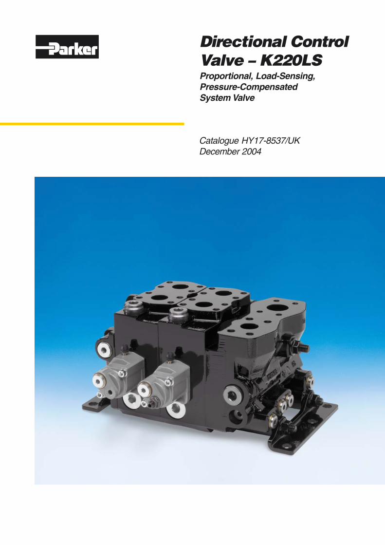
Catalogue HY17-8537/UKDecember 2004
Directional ControlValve – K220LSProportional, Load-Sensing,Pressure-CompensatedSystem Valve
2 Parker HannifinMobile Controls DivisionBorås, Sweden
Directional Control ValvesK220LS
Catalogue HY17-8537/UK
This catalog has been designed to give a brief overview ofK220LS valves, and to make it easy for you to study andchoose from the different options available, so that we may cus-tomize your valve in accordance with your wishes. In addition togeneral information and basic technical data, the catalog there-fore contains descriptions of the options available for variousso-called “function areas” of the valve.
Each function area is given as a subheading, followed by abrief description. When options are available for a functionarea, the subheading is followed by an “Item number” in brack-ets, e.g. PrPrPrPrPressuressuressuressuressure re re re re relief valve [16]elief valve [16]elief valve [16]elief valve [16]elief valve [16]. This is followed by a series
of coded options, e.g. PPPPPA1, Y1,A1, Y1,A1, Y1,A1, Y1,A1, Y1, together with a brief descrip-tion of what each code represents. Alternatively, one or morepressure, flow or voltage options are given.
On page 8 is a general circuit diagram showing the basicfunction areas in a K220LS valve and the item numbers thatrepresent them. Naturally, the same item numbers are used forthe respective function areas in all sub-circuit diagrams that ap-pear elsewhere in the catalog. Please note that, unless statedotherwise, all sections and views of the valves have been drawnas seen from the inlet section.
The K220LS directional control valve can be easily specifiedusing Parker computer programme. This means the customercan optimize his valve specification to give the best perform-ance for his application and specific hydraulic system.
Once the demands placed on each individual function havebeen specified the computer will select the valve design re-quired to give optimum performance. The computer also pro-duces complete documentation for your valve, in the form of adetailed specification and hydraulic circuit diagram.
The computer also generates a unique identification number foreach valve type and customer. The number is then stampedinto the I.D. plate of each valve. The specification of your valveis then recorded by Parker, so that exact identification of theproduct can be made at any time in the future to facilitate re-peat ordering or servicing.
Our experienced engineers have in-depth knowledge of thedifferent types of hydraulic system and the ways in which theywork. They are at your disposal to offer qualified advice on thebest system for the desired combination of functions, control
Catalog layout
How to order your valve
Early consultation with Parker saves time and moneycharacteristics and economic demands. By consulting Parkerearly in the project planning stage, you are assured of a com-prehensive hydraulic system that gives your machine the bestpossible operating and control characteristics.
Conversion factors1 kg = 2.2046 lb1 N = 0.22481 lbf1 bar = 14.504 psi1 l = 0.21997 UK gallon1 l = 0.26417 US gallon1 cm3 = 0.061024 in3
1 m = 3.2808 feet1 mm = 0.03937 in9/5 °C + 32 = °F
3 Parker HannifinMobile Controls DivisionBorås, Sweden
Directional Control ValvesK220LS
Catalogue HY17-8537/UK
Table of contents PageGeneral Information ................................................................................. 4Technical Data .........................................................................................5Inlet Section ............................................................................................. 7
Pressure setting [17] ........................................................................... 7Connections [04] and [47] .................................................................. 8Mid-inlet section [90-99] ..................................................................... 8
Spool Section ........................................................................................... 8Spool section with PC spool actuator ................................................. 8Feed reducer valve [75] ..................................................................... 9Setting of feed reducer in A-port [75A] .............................................. 9Setting of feed reducer in B-port [75B] .............................................. 9
Dimensional Drawings ...........................................................................10Mid-inlet section ..................................................................................... 10
[00] refers to item numbers in the customer specification.
4 Parker HannifinMobile Controls DivisionBorås, Sweden
Directional Control ValvesK220LS
Catalogue HY17-8537/UK
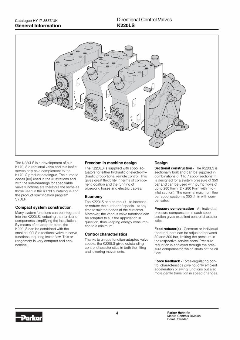
The K220LS is a development of ourK170LS directional valve and this leafletserves only as a complement to theK170LS product catalogue. The numericcodes [00] used in the illustrations andwith the sub-headings for specifiablevalve functions are therefore the same asthose used in the K170LS catalogue andthe product specification programSYBER.
Compact system constructionMany system functions can be integratedinto the K220LS, reducing the number ofcomponents simplifying the installation.By means of an adapter plate, theK220LS can be combined with thesmaller L90LS directional valve to servefunctions requiring lower flow. This ar-rangement is very compact and eco-nomical.
Freedom in machine designThe K220LS is supplied with spool ac-tuators for either hydraulic or electro-hy-draulic proportional remote control. Thisgives great flexibility in terms of compo-nent location and the running ofpipework, hoses and electric cables.
EconomyThe K220LS can be rebuilt - to increaseor reduce the number of spools - at anytime to suit the needs of the customer.Moreover, the various valve functions canbe adapted to suit the application inquestion, thus keeping energy consump-tion to a minimum.
Control characteristicsThanks to unique function-adapted valvespools, the K220LS gives outstandingcontrol characteristics in both the liftingand lowering movements.
DesignSectional construction - The K220LS issectionally built and can be supplied incombinations of 1 to 7 spool sections. Itis designed for a system pressure of 350bar and can be used with pump flows ofup to 280 l/min (2 x 280 l/min with mid-inlet section). The nominal maximum flowper spool section is 200 l/min with com-pensator.
Pressure compensation - An individualpressure compensator in each spoolsection gives excellent control character-istics.
Feed reducer(s) - Common or individualfeed reducers can be adjusted between30 and 300 bar, limiting the pressure inthe respective service ports. Pressurereduction is achieved through the pres-sure compensator, which shuts off the oilflow.
Force feedback - Force-regulating con-trol characteristics give not only efficientacceleration of swing functions but alsomore gentle transition in speed changes.
General Information
5 Parker HannifinMobile Controls DivisionBorås, Sweden
Directional Control ValvesK220LS
Catalogue HY17-8537/UK
PressurePump inlet max. 350 bar (5075 psi)1)
Service ports max. 350 bar (5075 psi)1)
Pump regulator ∆p min. 18 bar (260 psi)2)
Compensator K3 ∆p min. 30 bar (435 psi)2)
Return line pressure (static) max. 15 bar (215 psi)1) Stated pressures are maximal absolute shock pressures at10 bar (145 psi) tank pressure2) Pressure drop from pump to valve max. 3 bar (45 psi)
TemperatureOil temperature, working range +20 °C to +90 °C*
(68 to 194 °F)
* Product operating limits are broadly within the above range,but satisfactory operation within the specification may not beaccomplished. Leakage and response will be affected whenused at temperature extremes and it is up to the user to de-termine acceptability at these levels.
** Performance efficiency will be reduced if outside the idealvalues. These extreme conditions must be evaluated by theuser to establish suitability of the products performance.
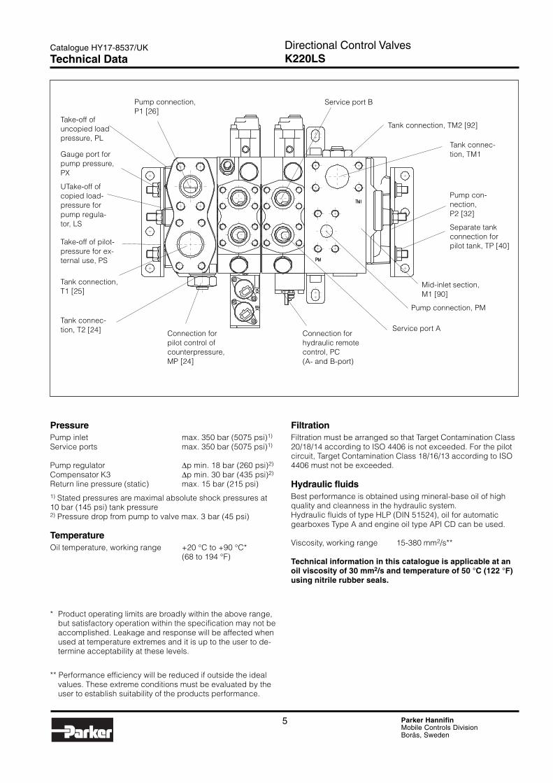
Pump connection,P1 [26]
Take-off ofuncopied loadpressure, PL
Gauge port forpump pressure,PX
UTake-off ofcopied load-pressure forpump regula-tor, LS
Take-off of pilot-pressure for ex-ternal use, PS
Tank connection,T1 [25]
Tank connec-tion, T2 [24] Connection for
pilot control ofcounterpressure,MP [24]
Connection forhydraulic remotecontrol, PC(A- and B-port)
Service port A
Pump con-nection,P2 [32]
Tank connection, TM2 [92]
Service port B
Tank connec-tion, TM1
Separate tankconnection forpilot tank, TP [40]
Pump connection, PM
Mid-inlet section,M1 [90]
Technical Data
FiltrationFiltration must be arranged so that Target Contamination Class20/18/14 according to ISO 4406 is not exceeded. For the pilotcircuit, Target Contamination Class 18/16/13 according to ISO4406 must not be exceeded.
Hydraulic fluidsBest performance is obtained using mineral-base oil of highquality and cleanness in the hydraulic system.Hydraulic fluids of type HLP (DIN 51524), oil for automaticgearboxes Type A and engine oil type API CD can be used.
Viscosity, working range 15-380 mm2/s**
Technical information in this catalogue is applicable at anoil viscosity of 30 mm2/s and temperature of 50 °C (122 °F)using nitrile rubber seals.
6 Parker HannifinMobile Controls DivisionBorås, Sweden
Directional Control ValvesK220LS
Catalogue HY17-8537/UK
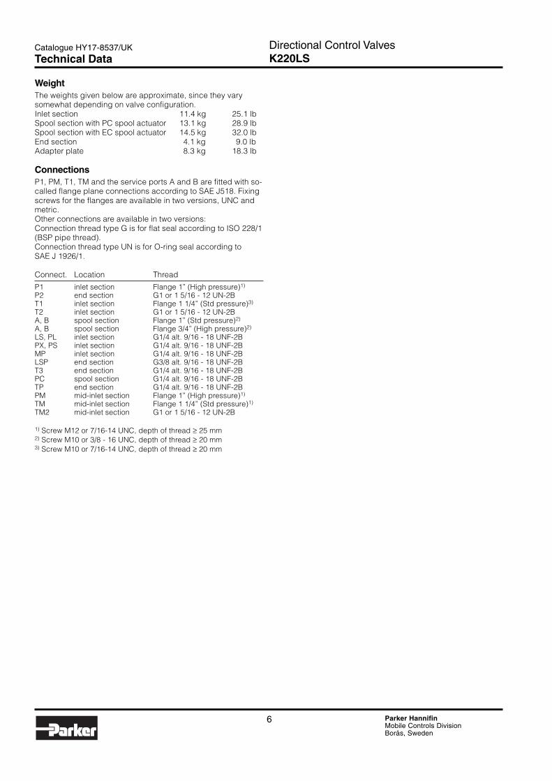
WeightThe weights given below are approximate, since they varysomewhat depending on valve configuration.Inlet section 11.4 kg 25.1 lbSpool section with PC spool actuator 13.1 kg 28.9 lbSpool section with EC spool actuator 14.5 kg 32.0 lbEnd section 4.1 kg 9.0 lbAdapter plate 8.3 kg 18.3 lb
ConnectionsP1, PM, T1, TM and the service ports A and B are fitted with so-called flange plane connections according to SAE J518. Fixingscrews for the flanges are available in two versions, UNC andmetric.Other connections are available in two versions:Connection thread type G is for flat seal according to ISO 228/1(BSP pipe thread).Connection thread type UN is for O-ring seal according toSAE J 1926/1.
Connect. Location Thread
P1 inlet section Flange 1” (High pressure)1)
P2 end section G1 or 1 5/16 - 12 UN-2BT1 inlet section Flange 1 1/4” (Std pressure)3)
T2 inlet section G1 or 1 5/16 - 12 UN-2BA, B spool section Flange 1” (Std pressure)2)
A, B spool section Flange 3/4” (High pressure)2)
LS, PL inlet section G1/4 alt. 9/16 - 18 UNF-2BPX, PS inlet section G1/4 alt. 9/16 - 18 UNF-2BMP inlet section G1/4 alt. 9/16 - 18 UNF-2BLSP end section G3/8 alt. 9/16 - 18 UNF-2BT3 end section G1/4 alt. 9/16 - 18 UNF-2BPC spool section G1/4 alt. 9/16 - 18 UNF-2BTP end section G1/4 alt. 9/16 - 18 UNF-2BPM mid-inlet section Flange 1” (High pressure)1)
TM mid-inlet section Flange 1 1/4” (Std pressure)1)
TM2 mid-inlet section G1 or 1 5/16 - 12 UN-2B
1) Screw M12 or 7/16-14 UNC, depth of thread ≥ 25 mm2) Screw M10 or 3/8 - 16 UNC, depth of thread ≥ 20 mm3) Screw M10 or 7/16-14 UNC, depth of thread ≥ 20 mm
Technical Data
7 Parker HannifinMobile Controls DivisionBorås, Sweden
Directional Control ValvesK220LS
Catalogue HY17-8537/UK
PA1 Direct-acting pressure relief valve PLC183 with veryfast opening sequence and good pressure character-istic. The replaceable PLC cartridge is factory set. Thecartridge has a replenishing function, which enablesoil to flow from the tank gallery to the pump gallery inthe event of underpressure in the pump circuit. See“Pressure setting [17]” for pressure values.
Y1 Plug that replaces the pressure relief valve. The Y1plug blocks the connection between pump and tankcompletely.
Pressure setting [17]
Pressure settings for PA1 [16]
The direct-acting pressure relief valve PA1 is deliveredfactory-set. The following standard pressure settings(in bar) are available: 50, 63, 80, 100, 125, 140, 160,175, 190, 210, 230, 240, 250, 260, 280, 300, 330 and350.
PA1 should be set 20 bar above the maximum pres-sure setting of the pump.
See also technical data on page 5-6.
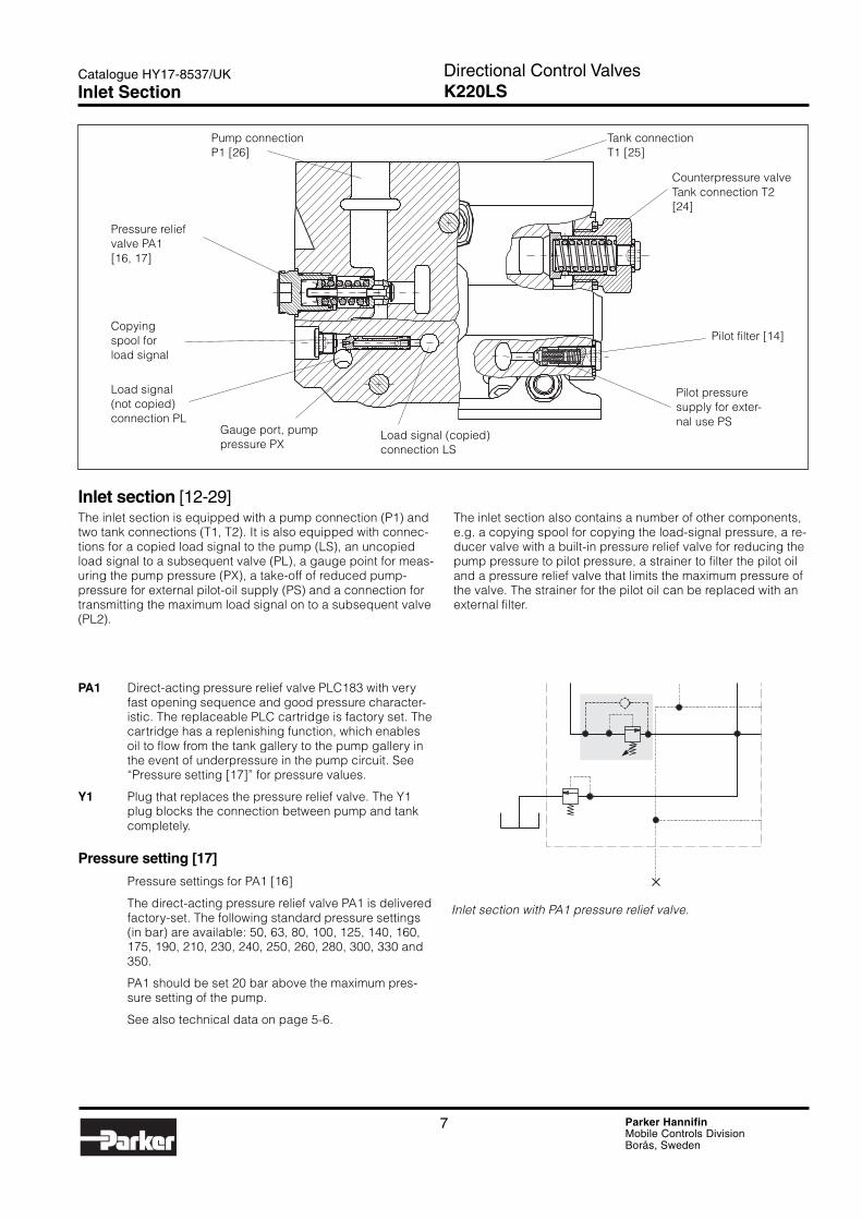
Inlet section [12-29]The inlet section is equipped with a pump connection (P1) andtwo tank connections (T1, T2). It is also equipped with connec-tions for a copied load signal to the pump (LS), an uncopiedload signal to a subsequent valve (PL), a gauge point for meas-uring the pump pressure (PX), a take-off of reduced pump-pressure for external pilot-oil supply (PS) and a connection fortransmitting the maximum load signal on to a subsequent valve(PL2).
The inlet section also contains a number of other components,e.g. a copying spool for copying the load-signal pressure, a re-ducer valve with a built-in pressure relief valve for reducing thepump pressure to pilot pressure, a strainer to filter the pilot oiland a pressure relief valve that limits the maximum pressure ofthe valve. The strainer for the pilot oil can be replaced with anexternal filter.
Pump connectionP1 [26]
Tank connectionT1 [25]
Counterpressure valveTank connection T2[24]
Copyingspool forload signal
Gauge port, pumppressure PX
Load signal(not copied)connection PL
Pilot filter [14]
Pilot pressuresupply for exter-nal use PS
Load signal (copied)connection LS
Pressure reliefvalve PA1[16, 17]
Inlet section with PA1 pressure relief valve.
Inlet Section
8 Parker HannifinMobile Controls DivisionBorås, Sweden
Directional Control ValvesK220LS
Catalogue HY17-8537/UK
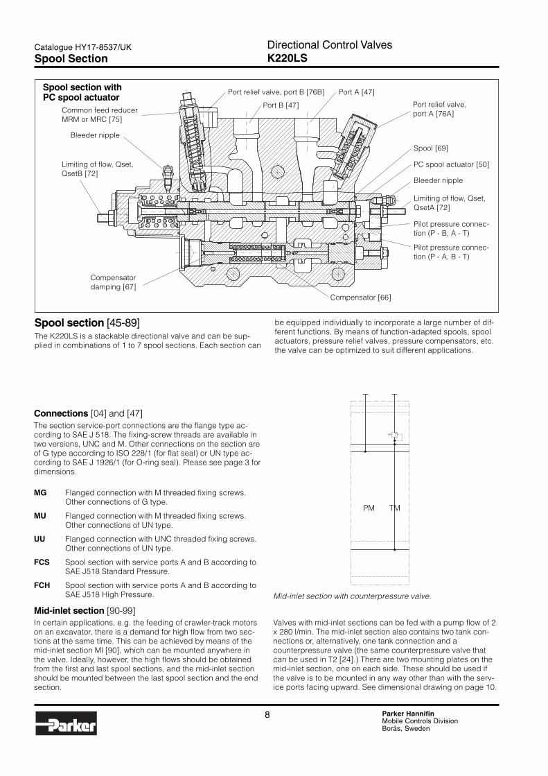
Spool section [45-89]The K220LS is a stackable directional valve and can be sup-plied in combinations of 1 to 7 spool sections. Each section can
Spool section withPC spool actuator
Bleeder nipple
Compensatordamping [67]
PC spool actuator [50]
Spool [69]
Compensator [66]
Common feed reducerMRM or MRC [75]
Port relief valve, port B [76B]
Port B [47]
Limiting of flow, Qset,QsetB [72]
Port A [47]
Port relief valve,port A [76A]
Bleeder nipple
Limiting of flow, Qset,QsetA [72]
Pilot pressure connec-tion (P - A, B - T)
Pilot pressure connec-tion (P - B, A - T)
Mid-inlet section with counterpressure valve.
PM TM
be equipped individually to incorporate a large number of dif-ferent functions. By means of function-adapted spools, spoolactuators, pressure relief valves, pressure compensators, etc.the valve can be optimized to suit different applications.
Connections [04] and [47]The section service-port connections are the flange type ac-cording to SAE J 518. The fixing-screw threads are available intwo versions, UNC and M. Other connections on the section areof G type according to ISO 228/1 (for flat seal) or UN type ac-cording to SAE J 1926/1 (for O-ring seal). Please see page 3 fordimensions.
MG Flanged connection with M threaded fixing screws.Other connections of G type.
MU Flanged connection with M threaded fixing screws.Other connections of UN type.
UU Flanged connection with UNC threaded fixing screws.Other connections of UN type.
FCS Spool section with service ports A and B according toSAE J518 Standard Pressure.
FCH Spool section with service ports A and B according toSAE J518 High Pressure.
Mid-inlet section [90-99]In certain applications, e.g. the feeding of crawler-track motorson an excavator, there is a demand for high flow from two sec-tions at the same time. This can be achieved by means of themid-inlet section Ml [90], which can be mounted anywhere inthe valve. Ideally, however, the high flows should be obtainedfrom the first and last spool sections, and the mid-inlet sectionshould be mounted between the last spool section and the endsection.
Spool Section
Valves with mid-inlet sections can be fed with a pump flow of 2x 280 l/min. The mid-inlet section also contains two tank con-nections or, alternatively, one tank connection and acounterpressure valve (the same counterpressure valve thatcan be used in T2 [24].) There are two mounting plates on themid-inlet section, one on each side. These should be used ifthe valve is to be mounted in any way other than with the serv-ice ports facing upward. See dimensional drawing on page 10.
9 Parker HannifinMobile Controls DivisionBorås, Sweden
Directional Control ValvesK220LS
Catalogue HY17-8537/UK
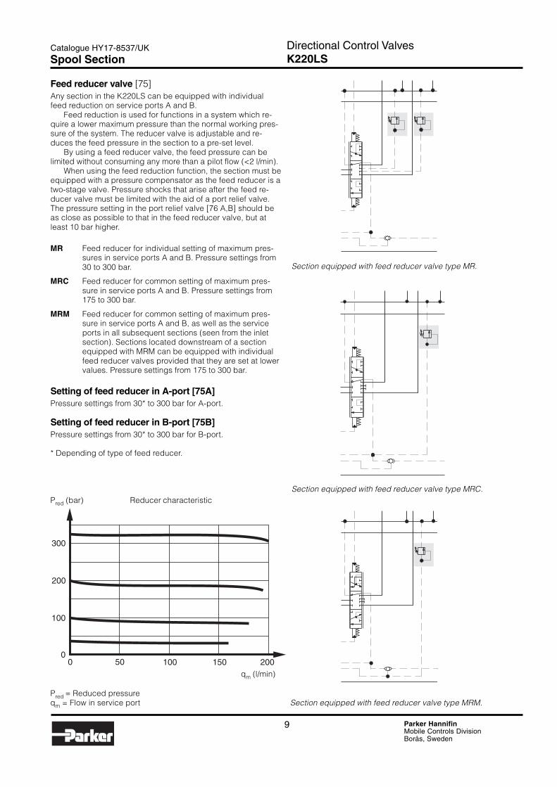
Pred (bar) Reducer characteristic
50 100 150 200
100
00
200
300
qm (l/min)
Pred = Reduced pressureqm = Flow in service port
Feed reducer valve [75]Any section in the K220LS can be equipped with individualfeed reduction on service ports A and B.
Feed reduction is used for functions in a system which re-quire a lower maximum pressure than the normal working pres-sure of the system. The reducer valve is adjustable and re-duces the feed pressure in the section to a pre-set level.
By using a feed reducer valve, the feed pressure can belimited without consuming any more than a pilot flow (<2 l/min).
When using the feed reduction function, the section must beequipped with a pressure compensator as the feed reducer is atwo-stage valve. Pressure shocks that arise after the feed re-ducer valve must be limited with the aid of a port relief valve.The pressure setting in the port relief valve [76 A,B] should beas close as possible to that in the feed reducer valve, but atleast 10 bar higher.
MR Feed reducer for individual setting of maximum pres-sures in service ports A and B. Pressure settings from30 to 300 bar.
MRC Feed reducer for common setting of maximum pres-sure in service ports A and B. Pressure settings from175 to 300 bar.
MRM Feed reducer for common setting of maximum pres-sure in service ports A and B, as well as the serviceports in all subsequent sections (seen from the inletsection). Sections located downstream of a sectionequipped with MRM can be equipped with individualfeed reducer valves provided that they are set at lowervalues. Pressure settings from 175 to 300 bar.
Setting of feed reducer in A-port [75A]Pressure settings from 30* to 300 bar for A-port.
Setting of feed reducer in B-port [75B]Pressure settings from 30* to 300 bar for B-port.
* Depending of type of feed reducer.
Section equipped with feed reducer valve type MR.
Section equipped with feed reducer valve type MRC.
Section equipped with feed reducer valve type MRM.
Spool Section
10 Parker HannifinMobile Controls DivisionBorås, Sweden
Directional Control ValvesK220LS
Catalogue HY17-8537/UK
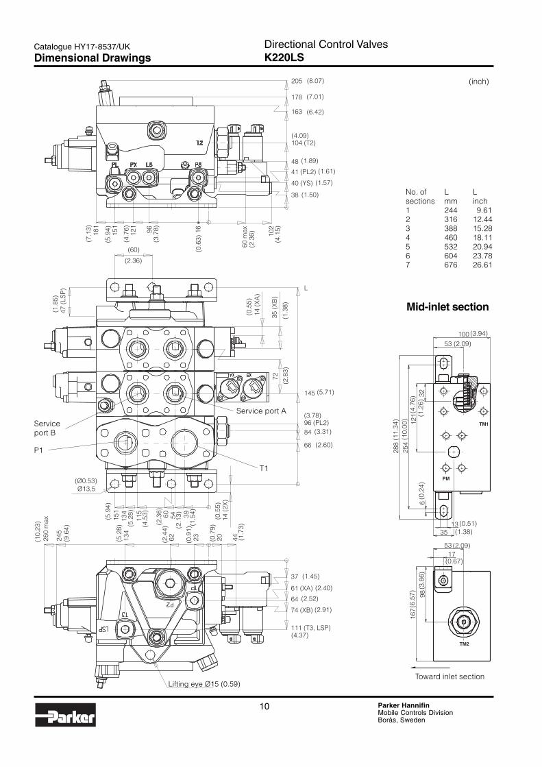
No. of L Lsections mm inch1 244 9.612 316 12.443 388 15.284 460 18.115 532 20.946 604 23.787 676 26.61
1696121
151
181
60 m
ax 102
38
40 (YS)
41 (PL2)
48
104 (T2)
163
178
205
(60)
47 (
LSP
) L
35 (
XB
)
14 (
XA
)
72
145
96 (PL2)84
66
14 (
2X)
395460115
134
151
Ø13,5
44202362134
245
260
max
111 (T3, LSP)
74 (XB)
64
61 (XA)
37
(10.
23)
(9.6
4)
(5.2
8)
(2.4
4)
(0.9
1)
(0.7
9)
(1.7
3)
(1.45)
(2.40)
(2.52)
(2.91)
(4.37)
(Ø0.53)
(5.9
4)
(5.2
8)
(4.5
3)
(2.3
6)
(2.1
3)
(1.5
4)
(0.5
5)
(2.60)
(3.31)
(3.78)
(5.71)
(0.5
5)
(1.3
8)(2
.83)
(1.8
5)
(2.36)
(7.1
3)
(5.9
4)
(4.7
6)
(3.7
8)
(0.6
3)
(2.3
6)
(4.1
5)
(1.50)
(1.57)
(1.61)
(1.89)
(4.09)
(6.42)
(7.01)
(8.07)
TM1
TM2
PM
53100
3212
125
428
8
6
1335
5317
9816
7(6
.57)
(3.8
6)
(2.09)
(0.67)
(0.51)(1.38)
(0.2
4)
(11.
34)
(10.
00)
(4.7
6)(1
.26)
(2.09)
(3.94)
Mid-inlet section
Toward inlet section
Serviceport B
Service port A
P1
T1
Lifting eye Ø15 (0.59)
(inch)
Dimensional Drawings

11 Parker HannifinMobile Controls DivisionBorås, Sweden
Directional Control ValvesK220LS
Catalogue HY17-8537/UK
Offer of SalePlease contact your Parker representation for a detailed ”Offer of Sale”.
FAILURE OR IMPROPER SELECTION OR IMPROPER USE OF THE PRODUCTS AND/OR SYSTEMS DESCRIBEDHEREIN OR RELATED ITEMS CAN CAUSE DEATH, PERSONAL INJURY AND PROPERTY DAMAGE.
This document and other information from Parker Hannifin Corporation, its subsidiaries and authorized distributors provideproduct and/or system options for further investigation by users having technical expertise. It is important that you analyze allaspects of your application, including consequences of any failure, and review the information concerning the product orsystem in the current product catalogue. Due to the variety of operating conditions and applications for these products orsystems, the user, through its own analysis and testing, is solely responsible for making the final selection of the products andsystems and assuring that all performance, safety and warning requirements of the application are met.
The products described herein, including without limitation, product features, specifications, designs, availability and pricing, aresubject to change by Parker Hannifin Corporation and its subsidiaries at any time without notice.
WARNING!
Parker Hannifin is the world’s premier supplier of motion and control systemsand solutions, with sales and manufacturing facilities throughout the world. Forproduct information and details of your nearest Parker sales office, visit us atwww.parker.com or call free on 00800 2727 5374.
Hydraulics GroupSales Offices
AustriaWiener NeustadtTel: +43 (0)2622 23501Fax: +43 (0)2622 66212
BelgiumNivellesTel: +32 (0)67 280 900Fax: +32 (0)67 280 999
Czech RepublicKlecanyTel: +420 284 083 111Fax: +420 284 083 112
DenmarkBallerupTel: +45 4356 0400Fax: +45 4373 8431
FinlandVantaaTel: +358 (0)9 4767 31Fax: +358 (0)9 4767 3200
FranceContamine-sur-ArveTel: +33 (0)450 25 80 25Fax: +33 (0)450 03 67 37
GermanyKaarstTel: +49 (0)2131 4016 0Fax: +49 (0)2131 4016 9199
HungaryBudapestTel: +36 (06)1 220 4155Fax: +36 (06)1 422 1525
IrelandDublinTel: +353 (0)1 293 9999Fax: +353 (0)1 293 9900
ItalyCorsico (MI)Tel: +39 02 45 19 21Fax: +39 02 4 47 93 40
The NetherlandsOldenzaalTel: +31 (0)541 585000Fax: +31 (0)541 585459
NorwaySkiTel: +47 64 91 10 00Fax: +47 64 91 10 90
PolandWarsawTel: +48 (0)22 863 49 42Fax: +48 (0)22 863 49 44
PortugalLeca da PalmeiraTel: +351 22 9997 360Fax: +351 22 9961 527
SlovakiaRef. Czech Republic
SpainMadridTel: +34 91 675 73 00Fax: +34 91 675 77 11
SwedenSpångaTel: +46 (0)8 597 950 00Fax: +46 (0)8 597 951 10
TurkeyMerter/IstanbulTel.: +90 212 482 91 06 or 07Fax: +90 212 482 91 10
United KingdomWarwickTel: +44 (0)1926 317 878Fax: +44 (0)1926 317 855
InternationalEurope
Catalogue HY17-8537/UKPDF 12/04
© Copyright 2004Parker Hannifin CorporationAll rights reserved.
AustraliaCastle HillTel: +61 (0)2-9634 7777Fax: +61 (0)2-9899 6184
CanadaMilton, OntarioTel: +1 905-693-3000Fax: +1 905-876-0788
ChinaBeijingTel: +86 10 6561 0520Fax: +86 10 6561 0526
Asia Pacific GroupHong Kong, KowloonTel: +852 2428 8008Fax: +852 2425 6896
IndiaMumbaiTel: +91 22 7907081Fax: +91 22 7907080
JapanTokyoTel: +(81) 3 6408 3900Fax: +(81) 3 5449 7201
Latin America GroupBrazilTel: +55 12 3954-5100Fax: +55 12 3954-5266
South AfricaKempton ParkTel: +27 (0)11-961 0700Fax: +27 (0)11-392 7213
USACleveland (industrial)Tel: +1 216-896-3000Fax: +1 216-896-4031Lincolnshire (mobile)Tel: +1 847-821-1500Fax: +1 847-821-7600