2.0 PROJECT DESCRIPTION - Keystone Pipeline · Keystone’s Environmental Report (ER), ... click on...
68
2-1 Final EIS Keystone XL Project 2.0 PROJECT DESCRIPTION Keystone proposes to construct, operate, maintain, inspect, and monitor a pipeline system that would transport crude oil from its existing facilities in Hardisty, Alberta, Canada to delivery points at Cushing, Oklahoma and in Texas. This section describes Keystone’s proposed action and includes the following information: Overview of the Proposed Project (Section 2.1); Aboveground Facilities (Section 2.2); Project Design and Construction Procedures (Section 2.3); Operations and Maintenance (Section 2.4); Connected Actions (Section 2.5); and Future Plans and Decommissioning (Section 2.6). Information presented in this EIS on the proposed Project was obtained from documents submitted to DOS by Keystone, including the following primary sources: Keystone’s application for a Presidential Permit; Keystone’s Environmental Report (ER), attachments to the ER, and related supplemental filings; Keystone’s General Conformity Determination; and Keystone’s responses to DOS data requests. The EIS includes basic graphics depicting key aspects of the proposed Project; more detailed alignment sheets are available at the DOS website for the proposed Project at: http://www.keystonepipeline- xl.state.gov/clientsite/keystonexl.nsf?Open. To access the documents, click on “Project Documents” then “Supplemental Filing.” In addition to the proposed Project, this EIS describes and addresses the impacts of four actions that are separate from the proposed Project and are not part of the Presidential Permit application submitted by Keystone. Those actions have been determined to be connected actions for the purposes of this NEPA review as defined by 40 CFR 1508.25(a)(1) and are described in Section 2.5. 2.1 OVERVIEW OF THE PROPOSED PROJECT The proposed Project would have the initial capacity to deliver up to 700,000 bpd of WCSB crude oil from the proposed Canada-U.S. border crossing to delivery points in Cushing, Oklahoma, in Nederland, Texas (near Port Arthur), and in Moore Junction, Texas (east of Houston). Keystone currently has binding commitments to ship 380,000 bpd of Canadian crude oil. The proposed Project could transport up to 830,000 bpd of crude oil by adding pumping capacity if warranted by future market demand. At the time of publication of the draft EIS, Keystone had applied to the PHMSA for consideration of a Special Permit request to operate the proposed Project at a slightly higher pressure than would be allowed using the standard design factor in the regulations. That would have resulted in a maximum crude oil throughput of approximately 900,000 bpd. DOS worked with PHMSA to develop Project-specific
Transcript of 2.0 PROJECT DESCRIPTION - Keystone Pipeline · Keystone’s Environmental Report (ER), ... click on...
2-1 Final EIS Keystone XL Project
2.0 PROJECT DESCRIPTION
Keystone proposes to construct, operate, maintain, inspect, and monitor a pipeline system that would
transport crude oil from its existing facilities in Hardisty, Alberta, Canada to delivery points at Cushing,
Oklahoma and in Texas. This section describes Keystone’s proposed action and includes the following
information:
Overview of the Proposed Project (Section 2.1);
Aboveground Facilities (Section 2.2);
Project Design and Construction Procedures (Section 2.3);
Operations and Maintenance (Section 2.4);
Connected Actions (Section 2.5); and
Future Plans and Decommissioning (Section 2.6).
Information presented in this EIS on the proposed Project was obtained from documents submitted to
DOS by Keystone, including the following primary sources:
Keystone’s application for a Presidential Permit;
Keystone’s Environmental Report (ER), attachments to the ER, and related supplemental filings;
Keystone’s General Conformity Determination; and
Keystone’s responses to DOS data requests.
The EIS includes basic graphics depicting key aspects of the proposed Project; more detailed alignment
sheets are available at the DOS website for the proposed Project at: http://www.keystonepipeline-
xl.state.gov/clientsite/keystonexl.nsf?Open. To access the documents, click on “Project Documents” then
“Supplemental Filing.”
In addition to the proposed Project, this EIS describes and addresses the impacts of four actions that are
separate from the proposed Project and are not part of the Presidential Permit application submitted by
Keystone. Those actions have been determined to be connected actions for the purposes of this NEPA
review as defined by 40 CFR 1508.25(a)(1) and are described in Section 2.5.
2.1 OVERVIEW OF THE PROPOSED PROJECT
The proposed Project would have the initial capacity to deliver up to 700,000 bpd of WCSB crude oil
from the proposed Canada-U.S. border crossing to delivery points in Cushing, Oklahoma, in Nederland,
Texas (near Port Arthur), and in Moore Junction, Texas (east of Houston). Keystone currently has
binding commitments to ship 380,000 bpd of Canadian crude oil. The proposed Project could transport
up to 830,000 bpd of crude oil by adding pumping capacity if warranted by future market demand.
At the time of publication of the draft EIS, Keystone had applied to the PHMSA for consideration of a
Special Permit request to operate the proposed Project at a slightly higher pressure than would be allowed
using the standard design factor in the regulations. That would have resulted in a maximum crude oil
throughput of approximately 900,000 bpd. DOS worked with PHMSA to develop Project-specific
2-2 Final EIS Keystone XL Project
Special Conditions that would have been incorporated into the Special Permit. On August 5, 2010,
Keystone withdrew its application to PHMSA for a Special Permit. To enhance the overall safety of the
proposed Project, DOS and PHMSA continued working on Special Conditions specific to the proposed
Project and ultimately established 57 Project-specific Special Conditions. As a result, Keystone agreed to
design, construct, operate, maintain, and monitor the proposed Project in accordance with the regulatory
requirements in 49 CFR Parts 194 and 195 as well as the more stringent set of 57 Project-specific Special
Conditions developed by PHMSA presented in Appendix U. As a result, the maximum throughput of the
proposed Project decreased and is currently proposed to be approximately 830,000 bpd. In addition, the
maximum operating pressure would be reduced from the requested 1,400 psig to 1,308 psig.
The proposed Project would deliver primarily WCSB crude oil (which would likely be heavy crude oil)
based on current market forecasts, to three delivery points in the U.S. that in turn provide access to many
other U.S. pipeline systems, terminals, and refineries. The ultimate destinations of the crude oil beyond
these delivery points would not be contracted with Keystone and therefore are not considered part of the
proposed Project.
The proposed Project includes three new pipeline segments in five states plus additional pumping
capacity on the existing Cushing Extension of the Keystone Oil Pipeline Project (See Figures 2.1-1
through 2.1-6). The proposed new pipeline segments are:
The Steele City Segment (from near Morgan, Montana to Steele City, Nebraska) − the southern
end of this segment would connect to the northern end of the existing Cushing Extension near
Steele City;
The Gulf Coast Segment (from Cushing, Oklahoma to Nederland, Texas) − the northern end of
this segment would connect to the southern end of the Cushing Extension at the Cushing tank
farm; and
The Houston Lateral (from the Gulf Coast Segment, in Liberty County, Texas to Moore Junction,
in Harris County, Texas).
The actual alignment continues to undergo small revisions based on ongoing landowner negotiations and
regulatory/resource agency input. The analysis in the EIS is based on the alignment as of March 26,
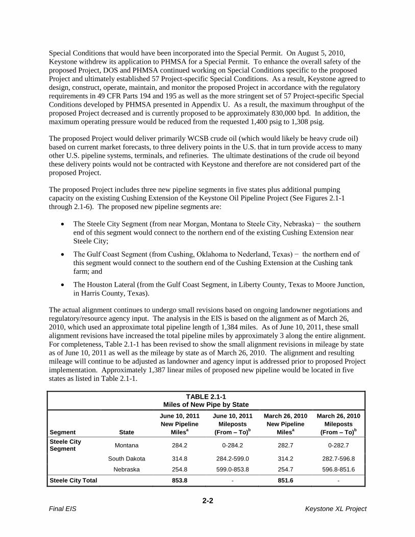
2010, which used an approximate total pipeline length of 1,384 miles. As of June 10, 2011, these small
alignment revisions have increased the total pipeline miles by approximately 3 along the entire alignment.
For completeness, Table 2.1-1 has been revised to show the small alignment revisions in mileage by state
as of June 10, 2011 as well as the mileage by state as of March 26, 2010. The alignment and resulting
mileage will continue to be adjusted as landowner and agency input is addressed prior to proposed Project
implementation. Approximately 1,387 linear miles of proposed new pipeline would be located in five
states as listed in Table 2.1-1.
TABLE 2.1-1 Miles of New Pipe by State
Segment State
June 10, 2011
New Pipeline
Milesa
June 10, 2011
Mileposts
(From – To)b
March 26, 2010
New Pipeline
Milesa
March 26, 2010
Mileposts
(From – To)b
Steele City Segment
Montana 284.2 0-284.2 282.7 0-282.7
South Dakota 314.8 284.2-599.0 314.2 282.7-596.8
Nebraska 254.8 599.0-853.8 254.7 596.8-851.6
Steele City Total 853.8 - 851.6 -

2-3 Final EIS Keystone XL Project
TABLE 2.1-1 Miles of New Pipe by State
Segment State
June 10, 2011
New Pipeline
Milesa
June 10, 2011
Mileposts
(From – To)b
March 26, 2010
New Pipeline
Milesa
March 26, 2010
Mileposts
(From – To)b
Keystone Cushing Extension
Nebraska 0 N/A 0 N/A
Kansas 0 N/A 0 N/A
Oklahoma 0 N/A 0 N/A
Gulf Coast Segment
Oklahoma 155.9 0‐155.9 155.7 0-155.7
Texas 328.4 155.9‐484.3 328.1 155.7-483.8
Gulf Coast Total 484.3 - 483.8 -
Houston Lateral Texas 48.6 0-48.6 48.6 0-48.6
Project Total 1,386.7 - 1,383.9 -
a Mileages are approximate and subject to change based on final approved design and routing.
b Mileposting for each segment of the proposed Project starts at 0.0 at the northernmost point of each segment and increases in
the direction of oil flow.
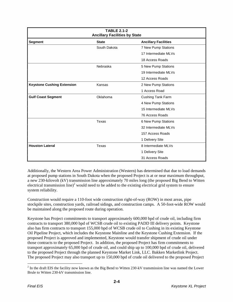
The proposed Project would include 30 new pump stations, mainline valves (MLVs) at the pump stations,
112 MLVs along the proposed pipeline (termed “intermediate” MLVs) based on current information, a
tank farm at Cushing, Oklahoma that would be a delivery point, one delivery point with a surge relief
system that includes two surge relief tanks at Nederland, and an oil delivery point and a surge relief
system without tanks at Moore Junction. These facilities are listed in Table 2.1-2 and are described in
more detail in Section 2.2.
Access roads, pipe stockpile sites, railroad sidings, and construction camps would also be required during
construction of the proposed Project. Electric power lines and associated facility upgrades would be
constructed, as required, by local providers to supply electrical power for the proposed new pump stations
and remotely operated valves and densitometers1 located along the pipeline route. Local power providers
would be responsible for obtaining the necessary approvals or authorizations from federal, state, and local
governments for such facilities. Although the permitting process for the electrical facilities is an
independent process, the construction and operation of these facilities are considered connected actions
under NEPA. Therefore, the potential impacts of the facilities were preliminarily evaluated as a part of
the NEPA environmental review described in this EIS based on currently available information.
TABLE 2.1-2 Ancillary Facilities by State
Segment State Ancillary Facilities
Steele City Segment Montana 6 New Pump Stations
21 Intermediate Mainline Valves (MLVs)
50 Access Roads
1 A densitometer is an on-line and continuous use device used to measure the density of a flowing stream. In the oil
and gas industry, a densitometer is normally used to measure the density of liquid hydrocarbon. The measurement
of density is used to determine the quantity of crude oil passing through a meter.
2-4 Final EIS Keystone XL Project
TABLE 2.1-2 Ancillary Facilities by State
Segment State Ancillary Facilities
South Dakota 7 New Pump Stations
17 Intermediate MLVs
18 Access Roads
Nebraska 5 New Pump Stations
19 Intermediate MLVs
12 Access Roads
Keystone Cushing Extension Kansas 2 New Pump Stations
1 Access Road
Gulf Coast Segment Oklahoma Cushing Tank Farm
4 New Pump Stations
15 Intermediate MLVs
76 Access Roads
Texas 6 New Pump Stations
32 Intermediate MLVs
157 Access Roads
1 Delivery Site
Houston Lateral Texas 8 Intermediate MLVs
1 Delivery Site
31 Access Roads
Additionally, the Western Area Power Administration (Western) has determined that due to load demands
at proposed pump stations in South Dakota when the proposed Project is at or near maximum throughput,
a new 230-kilovolt (kV) transmission line approximately 70 miles long (the proposed Big Bend to Witten
electrical transmission line)2 would need to be added to the existing electrical grid system to ensure
system reliability.
Construction would require a 110-foot wide construction right-of-way (ROW) in most areas, pipe
stockpile sites, construction yards, railroad sidings, and construction camps. A 50-foot-wide ROW would
be maintained along the proposed route during operation.
Keystone has Project commitments to transport approximately 600,000 bpd of crude oil, including firm
contracts to transport 380,000 bpd of WCSB crude oil to existing PADD III delivery points. Keystone
also has firm contracts to transport 155,000 bpd of WCSB crude oil to Cushing in its existing Keystone
Oil Pipeline Project, which includes the Keystone Mainline and the Keystone Cushing Extension. If the
proposed Project is approved and implemented, Keystone would transfer shipment of crude oil under
those contracts to the proposed Project. In addition, the proposed Project has firm commitments to
transport approximately 65,000 bpd of crude oil, and could ship up to 100,000 bpd of crude oil, delivered
to the proposed Project through the planned Keystone Market Link, LLC. Bakken Marketlink Project.
The proposed Project may also transport up to 150,000 bpd of crude oil delivered to the proposed Project
2 In the draft EIS the facility now known as the Big Bend to Witten 230-kV transmission line was named the Lower
Brule to Witten 230-kV transmission line.
2-5 Final EIS Keystone XL Project
through the planned Keystone Marketlink, LLC. Cushing Marketlink Project (both projects are considered
connected actions as defined by CEQ and are described in Section 2.5).
The proposed Project is planned to be in service in 2013, with the actual date dependant on receipt of all
necessary permits, approvals, and authorizations.
As noted in Section 1.1, the proposed Project would primarily deliver WCSB crude oil, which would
likely be heavy crude oil based on current market forecasts, to three delivery points in the U.S. that in turn
provide access to many other U.S. pipeline systems and terminals. The ultimate destinations of the crude
oil beyond these delivery points would not be contracted with Keystone and are not a part of the proposed
Project.
2.1.1 Proposed Route Segments
2.1.1.1 Steele City Segment
A total of approximately 852 miles of new pipeline would be constructed for the Steele City Segment.
Approximately 30 miles (4 percent) of the alignment would be within approximately 300 feet of currently
existing pipelines, utilities, or ROWs. The remaining 822 miles (96 percent) of the route would be new
ROW. Eighteen new pump stations would be constructed and operated on land parcels ranging in area
from 5 to 15 acres. New electrical distribution lines would be constructed and operated by local power
providers to service the pump stations. Those facilities are considered connected actions for the purposes
of this EIS and are described in Section 2.5.
A total of approximately 14,875 acres of lands would be affected during construction of the Steele City
Segment. Of this acreage, approximately 5,344 acres would be permanent ROW during operation.
2.1.1.2 Cushing Extension (New Pump Stations)
Two new pump stations would be constructed in Kansas along the existing Keystone Cushing Extension.
These pump stations would enable the proposed Project to maintain the pressure required to make crude
oil deliveries at the desired throughput volumes. The two new pump stations would disturb a total of
approximately 15 acres of land during both construction and operation of the proposed Project.
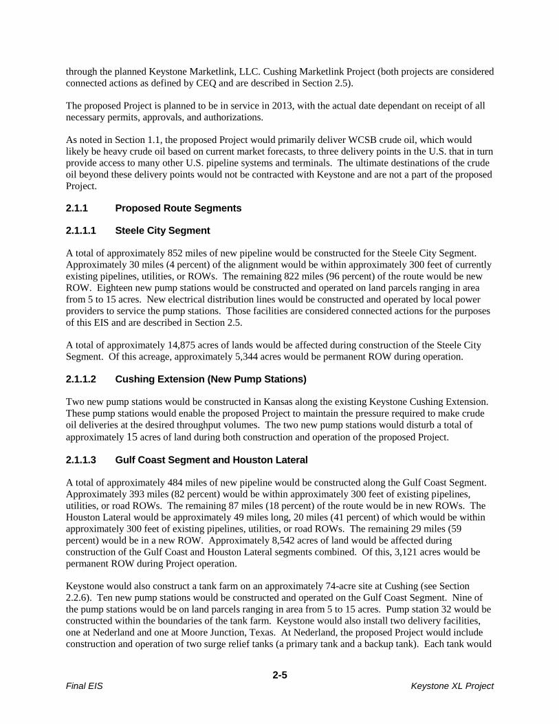
2.1.1.3 Gulf Coast Segment and Houston Lateral
A total of approximately 484 miles of new pipeline would be constructed along the Gulf Coast Segment.
Approximately 393 miles (82 percent) would be within approximately 300 feet of existing pipelines,
utilities, or road ROWs. The remaining 87 miles (18 percent) of the route would be in new ROWs. The
Houston Lateral would be approximately 49 miles long, 20 miles (41 percent) of which would be within
approximately 300 feet of existing pipelines, utilities, or road ROWs. The remaining 29 miles (59
percent) would be in a new ROW. Approximately 8,542 acres of land would be affected during
construction of the Gulf Coast and Houston Lateral segments combined. Of this, 3,121 acres would be
permanent ROW during Project operation.
Keystone would also construct a tank farm on an approximately 74-acre site at Cushing (see Section
2.2.6). Ten new pump stations would be constructed and operated on the Gulf Coast Segment. Nine of
the pump stations would be on land parcels ranging in area from 5 to 15 acres. Pump station 32 would be
constructed within the boundaries of the tank farm. Keystone would also install two delivery facilities,
one at Nederland and one at Moore Junction, Texas. At Nederland, the proposed Project would include
construction and operation of two surge relief tanks (a primary tank and a backup tank). Each tank would

2-6 Final EIS Keystone XL Project
have a capacity of approximately 10,417 barrels (435,514 gallons) with two carbon adsorption beds each,
in series. One tank would be on line at all times and the second would be on standby to be able to direct
crude oil in the proposed pipeline into one of the tanks to relieve pressure on the system during surge
events. Although the actual number of surge relief events that could occur during proposed Project
operations is not known, it was assumed that there would be an average of one surge relief event per
month for a total of 12 surge relief events per year (see Section 2.12 for additional information on the
surge relief system).
2.1.2 Land and Borrow Material Requirements
2.1.2.1 Land Requirements
Construction of the proposed Project would require a 110-foot-wide construction ROW. In certain
sensitive areas, which may include wetlands, cultural sites, shelterbelts, residential areas, or
commercial/industrial areas, the construction ROW would be reduced to 85 feet except in South Dakota
where it would be reduced to a 75-foot width unless the USACE requires an 85-foot width.
Figure 2.1.2-1 illustrates typical construction areas along the ROW where the route would not parallel an
existing pipeline corridor or another linear facility. Figures 2.1.2-2 and 2.1.2-3 illustrate typical
construction areas where the pipeline would parallel an existing linear feature.
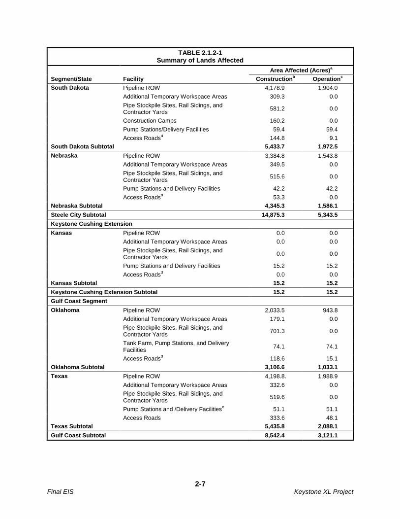
Approximately 24,134 acres of land would be disturbed during construction. The areas of surface
disturbance due to construction and operation of the proposed Project are listed in Table 2.1.2-1.
After construction, the temporary ROW (15,341 acres) would be restored consistent with applicable
federal and state regulations and permits, the easement agreements negotiated between Keystone and
individual landowners or land managers, and the construction methods and environmental protection
procedures described in the Keystone Construction, Mitigation, and Reclamation (CMR) plan (presented
in Appendix B and described in Section 2.3). Those measures would be incorporated into the proposed
Project to reduce the potential impacts of construction.
The permanent ROW would have an area of approximately 8,793 acres; of that total, 292 acres would be
the area of pump stations, valves, and other aboveground facilities. The permanent ROW would also be
restored as described above and to allow access to the ROW for the life of the proposed Project to support
surface and aerial inspections and any repairs or maintenance as necessary.
TABLE 2.1.2-1 Summary of Lands Affected
Segment/State Facility
Area Affected (Acres)a
Constructionb Operation
c
Steele City Segment
Montana Pipeline ROW 3,758.6 1,713.2
Additional Temporary Workspace Areas 327.8 0.0
Pipe Stockpile Sites, Rail Sidings, and Contractor Yards
460.7 0.0
Construction Camps 182.5 0.0
Pump Stations and Delivery Facilities 50.1 50.1
Access Roadsd 266.5 21.7
Montana Subtotal 5,046.3 1,785.0
2-7 Final EIS Keystone XL Project
TABLE 2.1.2-1 Summary of Lands Affected
Segment/State Facility
Area Affected (Acres)a
Constructionb Operation
c
South Dakota Pipeline ROW 4,178.9 1,904.0
Additional Temporary Workspace Areas 309.3 0.0
Pipe Stockpile Sites, Rail Sidings, and Contractor Yards
581.2 0.0
Construction Camps 160.2 0.0
Pump Stations/Delivery Facilities 59.4 59.4
Access Roadsd 144.8 9.1
South Dakota Subtotal 5,433.7 1,972.5
Nebraska Pipeline ROW 3,384.8 1,543.8
Additional Temporary Workspace Areas 349.5 0.0
Pipe Stockpile Sites, Rail Sidings, and Contractor Yards
515.6 0.0
Pump Stations and Delivery Facilities 42.2 42.2
Access Roadsd 53.3 0.0
Nebraska Subtotal 4,345.3 1,586.1
Steele City Subtotal 14,875.3 5,343.5
Keystone Cushing Extension
Kansas Pipeline ROW 0.0 0.0
Additional Temporary Workspace Areas 0.0 0.0
Pipe Stockpile Sites, Rail Sidings, and Contractor Yards
0.0 0.0
Pump Stations and Delivery Facilities 15.2 15.2
Access Roadsd 0.0 0.0
Kansas Subtotal 15.2 15.2
Keystone Cushing Extension Subtotal 15.2 15.2
Gulf Coast Segment
Oklahoma Pipeline ROW 2,033.5 943.8
Additional Temporary Workspace Areas 179.1 0.0
Pipe Stockpile Sites, Rail Sidings, and Contractor Yards
701.3 0.0
Tank Farm, Pump Stations, and Delivery Facilities
74.1 74.1
Access Roadsd 118.6 15.1
Oklahoma Subtotal 3,106.6 1,033.1
Texas Pipeline ROW 4,198.8. 1,988.9
Additional Temporary Workspace Areas 332.6 0.0
Pipe Stockpile Sites, Rail Sidings, and Contractor Yards
519.6 0.0
Pump Stations and /Delivery Facilitiese 51.1 51.1
Access Roads 333.6 48.1
Texas Subtotal 5,435.8 2,088.1
Gulf Coast Subtotal 8,542.4 3,121.1

2-8 Final EIS Keystone XL Project
TABLE 2.1.2-1 Summary of Lands Affected
Segment/State Facility
Area Affected (Acres)a
Constructionb Operation
c
Houston Lateral Pipeline ROW 652 294
Additional Temporary Workspace Areas 32 0
Pipe Storage Sites, Rail Sidings, and Contractor Yards
5 0
Access Roadsd 62 19
Houston Lateral Subtotal 751 313
Project Total 24,133.9 8,792.8
a Areas listed do not include the electrical distribution lines required for the pump stations. Information on the electrical distribution lines
is presented in Section 2.5.
bArea calculated based on a 110-foot-wide construction ROW except in certain wetlands, cultural sites, shelterbelts, residential areas,
and commercial/industrial areas where an 85-foot-wide construction ROW would be used, or in areas requiring extra width for workspace necessitated by site conditions.
c Area calculated based on a 50-foot-wide permanent ROW. All pigging facilities would be located within either pump stations or
delivery facility sites. Intermediate MLVs and densitometers would be within the permanent ROW.
d Access road area calculated based on 30-foot width.
e Keystone would install two 10,417-barrel surge tanks at the terminus of the Gulf Coast Segment on previously disturbed land.
2.1.2.2 Borrow Material Requirements
Borrow material would be required for temporary sites (such as storage sites, contractor yards, temporary
access roads, and access pads at ROW road crossings), to stabilize the land for permanent facilities
(including pump stations, valve sites, and permanent access roads), and for padding the bottom of the
pipeline trench in some areas. All gravel and other borrow material would be obtained from existing,
previously permitted commercial sources located as close to the pipe or contractor yards as possible.
Generally, about 7,000 cubic yards of gravel would be required for each pipe storage site and about
4,600 cubic yards of gravel would be required for each contractor yard. The approximately 400
temporary access roads would be graveled, as would access pads at ROW crossings of public and private
roads. Approximately 1,590 such road crossings are proposed. The 50 permanent access roads would
also be graveled. About 6 inches of gravel would typically be used at pump stations and MLV sites.
Along portions of the route, the trench bottom would be filled with padding material such as sand or
gravel, to protect the pipeline coating.
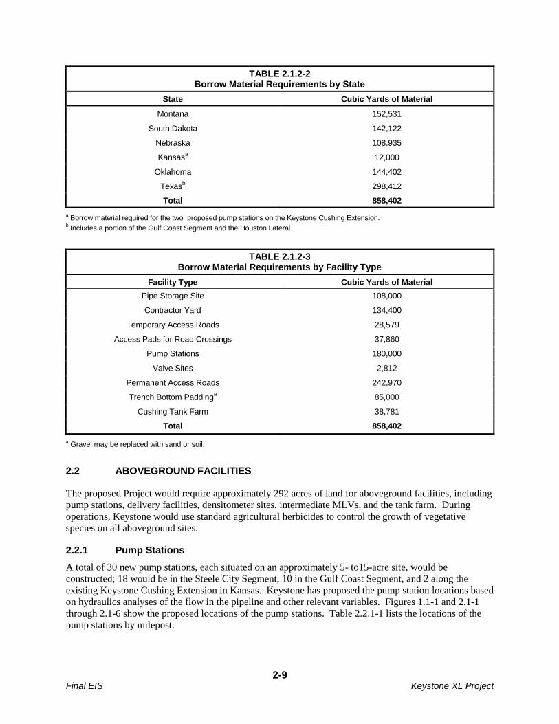
Table 2.1.2-2 lists the approximate amount of borrow material that would be required in each state, and
Table 2.1.2-3 lists the borrow material required for each facility type. Keystone would conduct detailed
surveys of pipe storage sites, railroad sidings, and contractor yards prior to construction to determine the
exact amounts of borrow material that would be required for each site.
2-9 Final EIS Keystone XL Project
TABLE 2.1.2-2 Borrow Material Requirements by State
State Cubic Yards of Material
Montana 152,531
South Dakota 142,122
Nebraska 108,935
Kansasa 12,000
Oklahoma 144,402
Texasb 298,412
Total 858,402
a Borrow material required for the two proposed pump stations on the Keystone Cushing Extension.
b Includes a portion of the Gulf Coast Segment and the Houston Lateral.
TABLE 2.1.2-3 Borrow Material Requirements by Facility Type
Facility Type Cubic Yards of Material
Pipe Storage Site 108,000
Contractor Yard 134,400
Temporary Access Roads 28,579
Access Pads for Road Crossings 37,860
Pump Stations 180,000
Valve Sites 2,812
Permanent Access Roads 242,970
Trench Bottom Paddinga 85,000
Cushing Tank Farm 38,781
Total 858,402
a Gravel may be replaced with sand or soil.
2.2 ABOVEGROUND FACILITIES
The proposed Project would require approximately 292 acres of land for aboveground facilities, including
pump stations, delivery facilities, densitometer sites, intermediate MLVs, and the tank farm. During
operations, Keystone would use standard agricultural herbicides to control the growth of vegetative
species on all aboveground sites.
2.2.1 Pump Stations
A total of 30 new pump stations, each situated on an approximately 5- to15-acre site, would be
constructed; 18 would be in the Steele City Segment, 10 in the Gulf Coast Segment, and 2 along the
existing Keystone Cushing Extension in Kansas. Keystone has proposed the pump station locations based
on hydraulics analyses of the flow in the pipeline and other relevant variables. Figures 1.1-1 and 2.1-1
through 2.1-6 show the proposed locations of the pump stations. Table 2.2.1-1 lists the locations of the
pump stations by milepost.
2-10 Final EIS Keystone XL Project
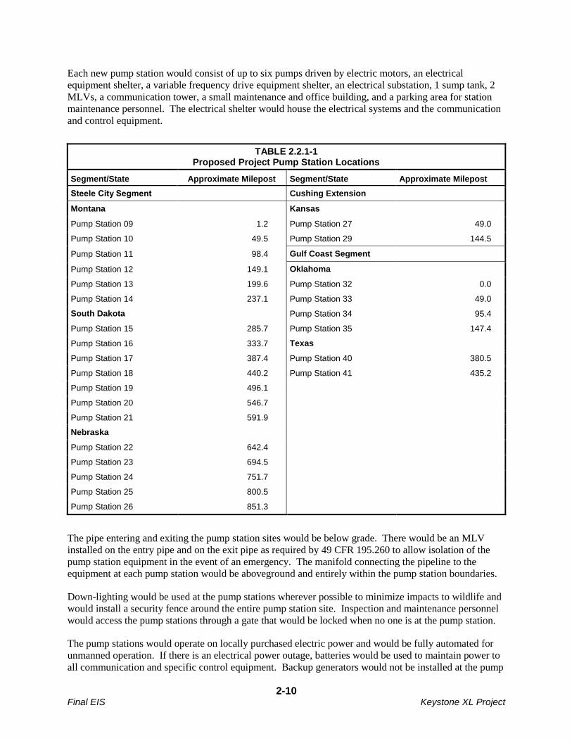
Each new pump station would consist of up to six pumps driven by electric motors, an electrical
equipment shelter, a variable frequency drive equipment shelter, an electrical substation, 1 sump tank, 2
MLVs, a communication tower, a small maintenance and office building, and a parking area for station
maintenance personnel. The electrical shelter would house the electrical systems and the communication
and control equipment.
TABLE 2.2.1-1 Proposed Project Pump Station Locations
Segment/State Approximate Milepost Segment/State Approximate Milepost
Steele City Segment Cushing Extension
Montana Kansas
Pump Station 09 1.2 Pump Station 27 49.0
Pump Station 10 49.5 Pump Station 29 144.5
Pump Station 11 98.4 Gulf Coast Segment
Pump Station 12 149.1 Oklahoma
Pump Station 13 199.6 Pump Station 32 0.0
Pump Station 14 237.1 Pump Station 33 49.0
South Dakota Pump Station 34 95.4
Pump Station 15 285.7 Pump Station 35 147.4
Pump Station 16 333.7 Texas
Pump Station 17 387.4 Pump Station 40 380.5
Pump Station 18 440.2 Pump Station 41 435.2
Pump Station 19 496.1
Pump Station 20 546.7
Pump Station 21 591.9
Nebraska
Pump Station 22 642.4
Pump Station 23 694.5
Pump Station 24 751.7
Pump Station 25 800.5
Pump Station 26 851.3
The pipe entering and exiting the pump station sites would be below grade. There would be an MLV
installed on the entry pipe and on the exit pipe as required by 49 CFR 195.260 to allow isolation of the
pump station equipment in the event of an emergency. The manifold connecting the pipeline to the
equipment at each pump station would be aboveground and entirely within the pump station boundaries.
Down-lighting would be used at the pump stations wherever possible to minimize impacts to wildlife and
would install a security fence around the entire pump station site. Inspection and maintenance personnel
would access the pump stations through a gate that would be locked when no one is at the pump station.
The pump stations would operate on locally purchased electric power and would be fully automated for
unmanned operation. If there is an electrical power outage, batteries would be used to maintain power to
all communication and specific control equipment. Backup generators would not be installed at the pump
2-11 Final EIS Keystone XL Project
stations and therefore there would not be fuel storage tanks at the pump stations. Communication towers
at pump stations generally would be approximately 33 feet high, but the antenna height at some pump
stations may be greater based on final detailed engineering studies. In no event would antennae exceed a
maximum height of 190 feet.
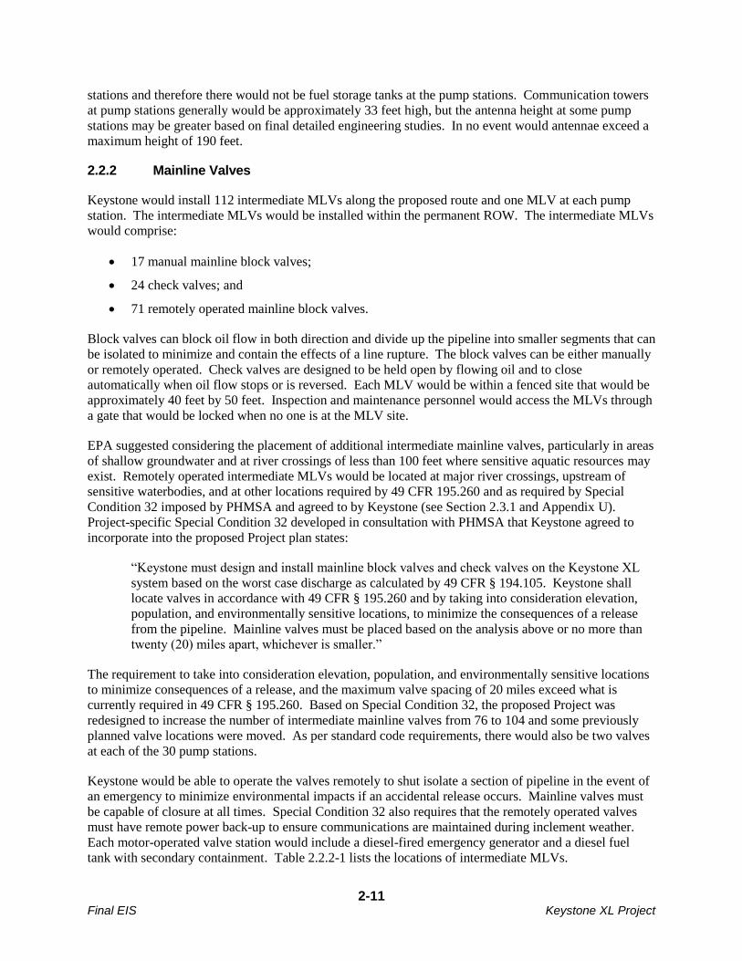
2.2.2 Mainline Valves
Keystone would install 112 intermediate MLVs along the proposed route and one MLV at each pump
station. The intermediate MLVs would be installed within the permanent ROW. The intermediate MLVs
would comprise:
17 manual mainline block valves;
24 check valves; and
71 remotely operated mainline block valves.
Block valves can block oil flow in both direction and divide up the pipeline into smaller segments that can
be isolated to minimize and contain the effects of a line rupture. The block valves can be either manually
or remotely operated. Check valves are designed to be held open by flowing oil and to close
automatically when oil flow stops or is reversed. Each MLV would be within a fenced site that would be
approximately 40 feet by 50 feet. Inspection and maintenance personnel would access the MLVs through
a gate that would be locked when no one is at the MLV site.
EPA suggested considering the placement of additional intermediate mainline valves, particularly in areas
of shallow groundwater and at river crossings of less than 100 feet where sensitive aquatic resources may
exist. Remotely operated intermediate MLVs would be located at major river crossings, upstream of
sensitive waterbodies, and at other locations required by 49 CFR 195.260 and as required by Special
Condition 32 imposed by PHMSA and agreed to by Keystone (see Section 2.3.1 and Appendix U).
Project-specific Special Condition 32 developed in consultation with PHMSA that Keystone agreed to
incorporate into the proposed Project plan states:
“Keystone must design and install mainline block valves and check valves on the Keystone XL
system based on the worst case discharge as calculated by 49 CFR § 194.105. Keystone shall
locate valves in accordance with 49 CFR § 195.260 and by taking into consideration elevation,
population, and environmentally sensitive locations, to minimize the consequences of a release
from the pipeline. Mainline valves must be placed based on the analysis above or no more than
twenty (20) miles apart, whichever is smaller.”
The requirement to take into consideration elevation, population, and environmentally sensitive locations
to minimize consequences of a release, and the maximum valve spacing of 20 miles exceed what is
currently required in 49 CFR § 195.260. Based on Special Condition 32, the proposed Project was
redesigned to increase the number of intermediate mainline valves from 76 to 104 and some previously
planned valve locations were moved. As per standard code requirements, there would also be two valves
at each of the 30 pump stations.
Keystone would be able to operate the valves remotely to shut isolate a section of pipeline in the event of
an emergency to minimize environmental impacts if an accidental release occurs. Mainline valves must
be capable of closure at all times. Special Condition 32 also requires that the remotely operated valves
must have remote power back-up to ensure communications are maintained during inclement weather.
Each motor-operated valve station would include a diesel-fired emergency generator and a diesel fuel
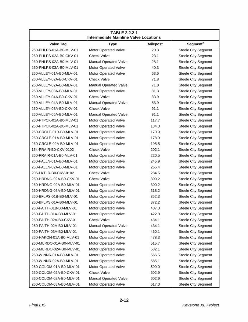
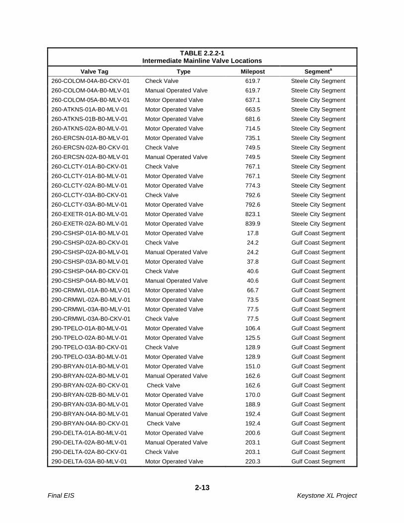
tank with secondary containment. Table 2.2.2-1 lists the locations of intermediate MLVs.
2-12 Final EIS Keystone XL Project
TABLE 2.2.2-1 Intermediate Mainline Valve Locations
Valve Tag Type Milepost Segmenta
260-PHLPS-01A-B0-MLV-01 Motor Operated Valve 20.3 Steele City Segment
260-PHLPS-02A-B0-CKV-01 Check Valve 28.1 Steele City Segment
260-PHLPS-02A-B0-MLV-01 Manual Operated Valve 28.1 Steele City Segment
260-PHLPS-03A-B0-MLV-01 Motor Operated Valve 40.3 Steele City Segment
260-VLLEY-01A-B0-MLV-01 Motor Operated Valve 63.6 Steele City Segment
260-VLLEY-02A-B0-CKV-01 Check Valve 71.8 Steele City Segment
260-VLLEY-02A-B0-MLV-01 Manual Operated Valve 71.8 Steele City Segment
260-VLLEY-03A-B0-MLV-01 Motor Operated Valve 81.3 Steele City Segment
260-VLLEY-04A-B0-CKV-01 Check Valve 83.9 Steele City Segment
260-VLLEY-04A-B0-MLV-01 Manual Operated Valve 83.9 Steele City Segment
260-VLLEY-05A-B0-CKV-01 Check Valve 91.1 Steele City Segment
260-VLLEY-05A-B0-MLV-01 Manual Operated Valve 91.1 Steele City Segment
260-FTPCK-01A-B0-MLV-01 Motor Operated Valve 117.7 Steele City Segment
260-FTPCK-02A-B0-MLV-01 Motor Operated Valve 134.3 Steele City Segment
260-CRCLE-01B-B0-MLV-01 Motor Operated Valve 170.9 Steele City Segment
260-CRCLE-01A-B0-MLV-01 Motor Operated Valve 178.9 Steele City Segment
260-CRCLE-02A-B0-MLV-01 Motor Operated Valve 195.5 Steele City Segment
154-PRAIR-B0-CKV-0102 Check Valve 202.1 Steele City Segment
260-PRAIR-01A-B0-MLV-01 Motor Operated Valve 220.5 Steele City Segment
260-FALLN-01A-B0-MLV-01 Motor Operated Valve 245.9 Steele City Segment
260-FALLN-02A-B0-MLV-01 Motor Operated Valve 266.4 Steele City Segment
206-LKTLR-B0-CKV-0102 Check Valve 284.5 Steele City Segment
260-HRDNG-02A-B0-CKV-01 Check Valve 300.2 Steele City Segment
260-HRDNG-02A-B0-MLV-01 Motor Operated Valve 300.2 Steele City Segment
260-HRDNG-03A-B0-MLV-01 Motor Operated Valve 318.2 Steele City Segment
260-BFLPS-01B-B0-MLV-01 Motor Operated Valve 352.3 Steele City Segment
260-BFLPS-01A-B0-MLV-01 Motor Operated Valve 372.2 Steele City Segment
260-FAITH-01B-B0-MLV-01 Motor Operated Valve 407.3 Steele City Segment
260-FAITH-01A-B0-MLV-01 Motor Operated Valve 422.8 Steele City Segment
260-FAITH-02A-B0-CKV-01 Check Valve 434.1 Steele City Segment
260-FAITH-02A-B0-MLV-01 Manual Operated Valve 434.1 Steele City Segment
260-FAITH-03A-B0-MLV-01 Motor Operated Valve 460.1 Steele City Segment
260-HAKON-01A-B0-MLV-01 Motor Operated Valve 478.3 Steele City Segment
260-MURDO-01A-B0-MLV-01 Motor Operated Valve 515.7 Steele City Segment
260-MURDO-02A-B0-MLV-01 Motor Operated Valve 532.1 Steele City Segment
260-WINNR-01A-B0-MLV-01 Motor Operated Valve 566.5 Steele City Segment
260-WINNR-02A-B0-MLV-01 Motor Operated Valve 585.1 Steele City Segment
260-COLOM-01A-B0-MLV-01 Motor Operated Valve 599.0 Steele City Segment
260-COLOM-02A-B0-CKV-01 Check Valve 602.9 Steele City Segment
260-COLOM-02A-B0-MLV-01 Manual Operated Valve 602.9 Steele City Segment
260-COLOM-03A-B0-MLV-01 Motor Operated Valve 617.3 Steele City Segment
2-13 Final EIS Keystone XL Project
TABLE 2.2.2-1 Intermediate Mainline Valve Locations
Valve Tag Type Milepost Segmenta
260-COLOM-04A-B0-CKV-01 Check Valve 619.7 Steele City Segment
260-COLOM-04A-B0-MLV-01 Manual Operated Valve 619.7 Steele City Segment
260-COLOM-05A-B0-MLV-01 Motor Operated Valve 637.1 Steele City Segment
260-ATKNS-01A-B0-MLV-01 Motor Operated Valve 663.5 Steele City Segment
260-ATKNS-01B-B0-MLV-01 Motor Operated Valve 681.6 Steele City Segment
260-ATKNS-02A-B0-MLV-01 Motor Operated Valve 714.5 Steele City Segment
260-ERCSN-01A-B0-MLV-01 Motor Operated Valve 735.1 Steele City Segment
260-ERCSN-02A-B0-CKV-01 Check Valve 749.5 Steele City Segment
260-ERCSN-02A-B0-MLV-01 Manual Operated Valve 749.5 Steele City Segment
260-CLCTY-01A-B0-CKV-01 Check Valve 767.1 Steele City Segment
260-CLCTY-01A-B0-MLV-01 Motor Operated Valve 767.1 Steele City Segment
260-CLCTY-02A-B0-MLV-01 Motor Operated Valve 774.3 Steele City Segment
260-CLCTY-03A-B0-CKV-01 Check Valve 792.6 Steele City Segment
260-CLCTY-03A-B0-MLV-01 Motor Operated Valve 792.6 Steele City Segment
260-EXETR-01A-B0-MLV-01 Motor Operated Valve 823.1 Steele City Segment
260-EXETR-02A-B0-MLV-01 Motor Operated Valve 839.9 Steele City Segment
290-CSHSP-01A-B0-MLV-01 Motor Operated Valve 17.8 Gulf Coast Segment
290-CSHSP-02A-B0-CKV-01 Check Valve 24.2 Gulf Coast Segment
290-CSHSP-02A-B0-MLV-01 Manual Operated Valve 24.2 Gulf Coast Segment
290-CSHSP-03A-B0-MLV-01 Motor Operated Valve 37.8 Gulf Coast Segment
290-CSHSP-04A-B0-CKV-01 Check Valve 40.6 Gulf Coast Segment
290-CSHSP-04A-B0-MLV-01 Manual Operated Valve 40.6 Gulf Coast Segment
290-CRMWL-01A-B0-MLV-01 Motor Operated Valve 66.7 Gulf Coast Segment
290-CRMWL-02A-B0-MLV-01 Motor Operated Valve 73.5 Gulf Coast Segment
290-CRMWL-03A-B0-MLV-01 Motor Operated Valve 77.5 Gulf Coast Segment
290-CRMWL-03A-B0-CKV-01 Check Valve 77.5 Gulf Coast Segment
290-TPELO-01A-B0-MLV-01 Motor Operated Valve 106.4 Gulf Coast Segment
290-TPELO-02A-B0-MLV-01 Motor Operated Valve 125.5 Gulf Coast Segment
290-TPELO-03A-B0-CKV-01 Check Valve 128.9 Gulf Coast Segment
290-TPELO-03A-B0-MLV-01 Motor Operated Valve 128.9 Gulf Coast Segment
290-BRYAN-01A-B0-MLV-01 Motor Operated Valve 151.0 Gulf Coast Segment
290-BRYAN-02A-B0-MLV-01 Manual Operated Valve 162.6 Gulf Coast Segment
290-BRYAN-02A-B0-CKV-01 Check Valve 162.6 Gulf Coast Segment
290-BRYAN-02B-B0-MLV-01 Motor Operated Valve 170.0 Gulf Coast Segment
290-BRYAN-03A-B0-MLV-01 Motor Operated Valve 188.9 Gulf Coast Segment
290-BRYAN-04A-B0-MLV-01 Manual Operated Valve 192.4 Gulf Coast Segment
290-BRYAN-04A-B0-CKV-01 Check Valve 192.4 Gulf Coast Segment
290-DELTA-01A-B0-MLV-01 Motor Operated Valve 200.6 Gulf Coast Segment
290-DELTA-02A-B0-MLV-01 Manual Operated Valve 203.1 Gulf Coast Segment
290-DELTA-02A-B0-CKV-01 Check Valve 203.1 Gulf Coast Segment
290-DELTA-03A-B0-MLV-01 Motor Operated Valve 220.3 Gulf Coast Segment
2-14 Final EIS Keystone XL Project
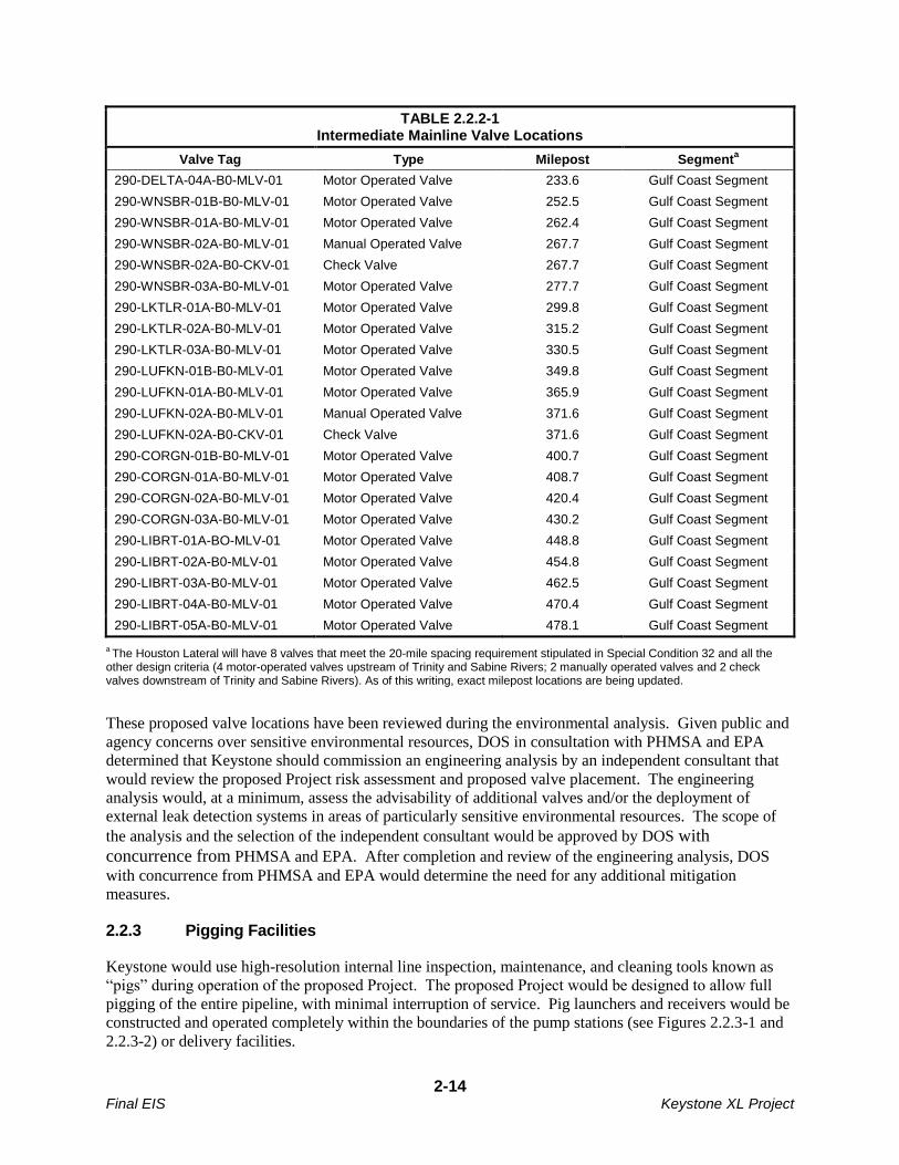
TABLE 2.2.2-1 Intermediate Mainline Valve Locations
Valve Tag Type Milepost Segmenta
290-DELTA-04A-B0-MLV-01 Motor Operated Valve 233.6 Gulf Coast Segment
290-WNSBR-01B-B0-MLV-01 Motor Operated Valve 252.5 Gulf Coast Segment
290-WNSBR-01A-B0-MLV-01 Motor Operated Valve 262.4 Gulf Coast Segment
290-WNSBR-02A-B0-MLV-01 Manual Operated Valve 267.7 Gulf Coast Segment
290-WNSBR-02A-B0-CKV-01 Check Valve 267.7 Gulf Coast Segment
290-WNSBR-03A-B0-MLV-01 Motor Operated Valve 277.7 Gulf Coast Segment
290-LKTLR-01A-B0-MLV-01 Motor Operated Valve 299.8 Gulf Coast Segment
290-LKTLR-02A-B0-MLV-01 Motor Operated Valve 315.2 Gulf Coast Segment
290-LKTLR-03A-B0-MLV-01 Motor Operated Valve 330.5 Gulf Coast Segment
290-LUFKN-01B-B0-MLV-01 Motor Operated Valve 349.8 Gulf Coast Segment
290-LUFKN-01A-B0-MLV-01 Motor Operated Valve 365.9 Gulf Coast Segment
290-LUFKN-02A-B0-MLV-01 Manual Operated Valve 371.6 Gulf Coast Segment
290-LUFKN-02A-B0-CKV-01 Check Valve 371.6 Gulf Coast Segment
290-CORGN-01B-B0-MLV-01 Motor Operated Valve 400.7 Gulf Coast Segment
290-CORGN-01A-B0-MLV-01 Motor Operated Valve 408.7 Gulf Coast Segment
290-CORGN-02A-B0-MLV-01 Motor Operated Valve 420.4 Gulf Coast Segment
290-CORGN-03A-B0-MLV-01 Motor Operated Valve 430.2 Gulf Coast Segment
290-LIBRT-01A-BO-MLV-01 Motor Operated Valve 448.8 Gulf Coast Segment
290-LIBRT-02A-B0-MLV-01 Motor Operated Valve 454.8 Gulf Coast Segment
290-LIBRT-03A-B0-MLV-01 Motor Operated Valve 462.5 Gulf Coast Segment
290-LIBRT-04A-B0-MLV-01 Motor Operated Valve 470.4 Gulf Coast Segment
290-LIBRT-05A-B0-MLV-01 Motor Operated Valve 478.1 Gulf Coast Segment
a The Houston Lateral will have 8 valves that meet the 20-mile spacing requirement stipulated in Special Condition 32 and all the
other design criteria (4 motor-operated valves upstream of Trinity and Sabine Rivers; 2 manually operated valves and 2 check valves downstream of Trinity and Sabine Rivers). As of this writing, exact milepost locations are being updated.
These proposed valve locations have been reviewed during the environmental analysis. Given public and
agency concerns over sensitive environmental resources, DOS in consultation with PHMSA and EPA
determined that Keystone should commission an engineering analysis by an independent consultant that
would review the proposed Project risk assessment and proposed valve placement. The engineering
analysis would, at a minimum, assess the advisability of additional valves and/or the deployment of
external leak detection systems in areas of particularly sensitive environmental resources. The scope of
the analysis and the selection of the independent consultant would be approved by DOS with
concurrence from PHMSA and EPA. After completion and review of the engineering analysis, DOS
with concurrence from PHMSA and EPA would determine the need for any additional mitigation
measures.
2.2.3 Pigging Facilities
Keystone would use high-resolution internal line inspection, maintenance, and cleaning tools known as
“pigs” during operation of the proposed Project. The proposed Project would be designed to allow full
pigging of the entire pipeline, with minimal interruption of service. Pig launchers and receivers would be
constructed and operated completely within the boundaries of the pump stations (see Figures 2.2.3-1 and
2.2.3-2) or delivery facilities.
2-15 Final EIS Keystone XL Project
2.2.4 Densitometer Facilities
Densitometer facilities on the pipeline would be equipped with densitometer/viscometer analyzers which
measure the density of the product prior to delivery. Densitometer information would be incorporated
into quality and custody metering located at all injection points and at all delivery points.
Keystone proposes to install and operate four densitometers within the permanent ROW. One of the
densitometers would be on the Steele City Segment, two would be on the Gulf Coast Segment, and one
would be on the Houston Lateral. The locations of the densitometers are listed below:
Upstream side of Pump Station 26 (Saline County, Nebraska; MP SCS-820.8);
Upstream side of Pump Station 41 (Liberty County, Texas; MP GCS-429.9);
Upstream side of the Nederland delivery station (Jefferson County Texas; MP GCS-477.8); and
Upstream side of the delivery station near Moore Junction (Harris County Texas; MP HL-42.6).
2.2.5 Delivery Sites
Keystone would install two crude oil delivery facilities in Texas. One would be at the end of the Gulf
Coast Segment in Nederland within a terminal owned and operated by Sunoco Logistics. The second
would be installed at the end of the Houston Lateral at Moore Junction on a previously disturbed site.
Each delivery facility would have a pig receiver on the incoming pipeline and would connect to a surge
relief system and a metering system installed upstream of a manifold owned by the third party receiving
crude oil transported by the proposed Project. The surge relief system at the Nederland delivery site
would include two surge relief tanks, each with a capacity of approximately 10,417 barrels (435,514
gallons) (see Section 2.1.1.3). The delivery facilities would also include pressure regulating equipment,
flow control valves, isolation valves, and a quality measurement building that would include a
densitometer and a sampling system. Each delivery facility would also include a sump tank with injection
pumps to receive oil from the drains of safety valves and traps. The drain system piping would connect to
the main line to return captured oil to the pipeline.
The delivery facilities would operate on locally provided power.
2.2.6 Cushing Tank Farm
Keystone originally proposed to construct a tank farm in Steele City, Nebraska to manage the movement
of oil through the system. However, after completing a detailed operational review of the proposed
Project, Keystone determined that there would be greater operational efficiency if the tank farm were
installed near Cushing, adjacent to the existing Cushing Oil Terminal, which is the largest crude oil
storage facility in the U.S. and has a substantial network of connecting crude oil pipelines.
Keystone proposes to construct a tank farm on an approximately 74-acre site that is approximately 2,000
feet from the southern end of the existing Cushing Oil Terminal. The site would also include Pump
Station 32. The plot plan for the Cushing tank farm is presented on Figure 2.2.6-1. As indicated on that
figure, there is sufficient room on the site to house the facilities proposed for the Bakken and Cushing
Marketlink projects, which are two connected actions described in Sections 2.5.3 and 2.5.4.
The Cushing tank farm would include three, 350,000-barrel aboveground storage tanks. Each tank would
have a single-deck pontoon external floating roof with provisions for installation of geodesic fixed roofs.
The tanks would be installed inside an impervious bermed area that would act as secondary containment.
The piping in the tank farm site would be both above and below ground. The tank farm would also
2-16 Final EIS Keystone XL Project
include four booster pumps, two sump tanks, two positive displacement meters, pig launchers and
receivers, two electrical buildings, a field service building, and parking for maintenance personnel. The
tanks and associated piping would be isolated electrically from the pipeline and protected by a separate
cathodic protection system. The tank farm would operate on locally purchased electricity and would be
fully automated for unmanned operation.
Down-lighting would be used to light the tank farm wherever possible to minimize impacts to wildlife. A
security fence would be installed around the entire tank farm. Inspection and maintenance personnel
would access the tank farm through a gate that would be locked when no one is at the tank farm.
In addition to the design requirements for the pipe for the proposed Project, procedures, specifications,
applicable codes and standards promulgated by the organizations listed below would be used for the
design of the Cushing tank farm facility:
Oklahoma Corporation commission – adopts DOT part 195 as outlined in Oklahoma
Administrative Code 165 Chapter 20, Gas and Hazardous Liquid Pipeline
American Petroleum Institute – API
American Society of Testing and Materials – ASTM
American Welding Society – AWS
Institute of Electrical and Electronics Engineers – IEEE
Instrument Society of America – ISA
International Organization for Standardization – ISO
Manufacturers Standardization Society of the Valve and fittings industry – MSS
National Electrical Safety Code – NEC
National Electrical Manufacturers Association – NEMA
National Fire Protection Association – NFPA
Occupational Safety and Health Administration – OSHA
Pipeline and Hazardous Material Safety Administration – PHMSA
Steel Structure Painting Council – SSPC
Underwriters Laboratories – UL
2.2.7 Ancillary Facilities
2.2.7.1 Additional Temporary Workspace Areas
Additional temporary workspace areas would be needed for some construction staging areas and where
special construction techniques are to be used. These areas would include river, wetland, and road/rail
crossings; horizontal directional drilling (HDD) entry and exit points; steep slopes (20 to 60 percent); and
rocky soils. The setback distances of temporary workspace areas adjacent to wetland and waterbody
features would be established on a site-specific basis, consistent with applicable permit requirements and
the appropriate procedures listed in the CMR Plan (Appendix B). The location of additional temporary
workspace areas would be adjusted as design of the proposed Project is refined.
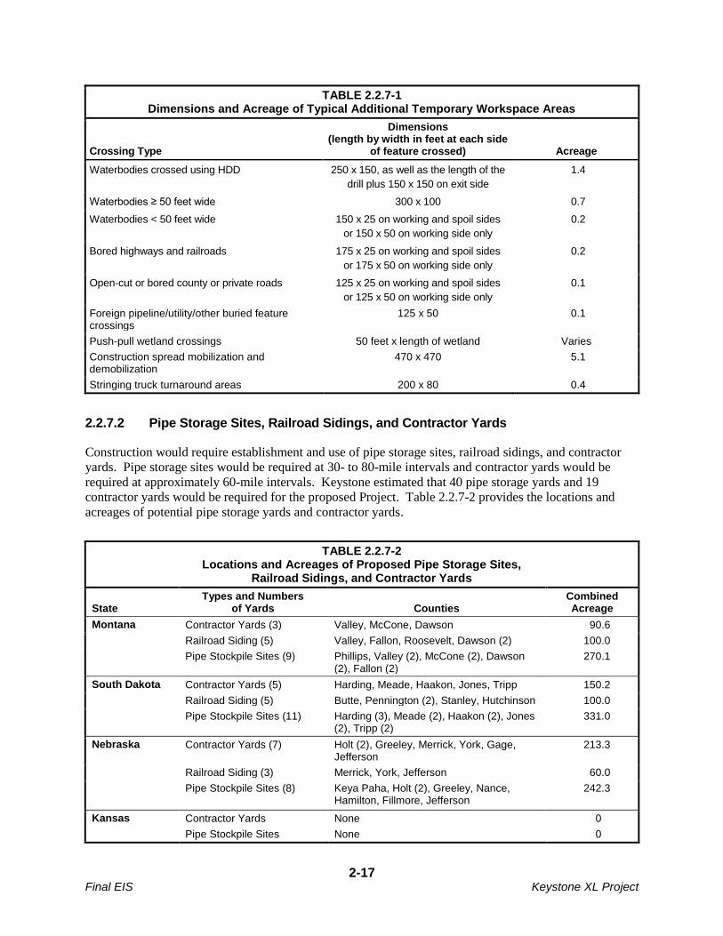
The dimensions and acreages of typical additional temporary workspace areas are listed in Table 2.2.7-1.
2-17 Final EIS Keystone XL Project
TABLE 2.2.7-1 Dimensions and Acreage of Typical Additional Temporary Workspace Areas
Crossing Type
Dimensions (length by width in feet at each side
of feature crossed) Acreage
Waterbodies crossed using HDD 250 x 150, as well as the length of the
drill plus 150 x 150 on exit side
1.4
Waterbodies ≥ 50 feet wide 300 x 100 0.7
Waterbodies < 50 feet wide 150 x 25 on working and spoil sides
or 150 x 50 on working side only
0.2
Bored highways and railroads 175 x 25 on working and spoil sides
or 175 x 50 on working side only
0.2
Open-cut or bored county or private roads 125 x 25 on working and spoil sides
or 125 x 50 on working side only
0.1
Foreign pipeline/utility/other buried feature crossings
125 x 50 0.1
Push-pull wetland crossings 50 feet x length of wetland Varies
Construction spread mobilization and demobilization
470 x 470 5.1
Stringing truck turnaround areas 200 x 80 0.4
2.2.7.2 Pipe Storage Sites, Railroad Sidings, and Contractor Yards
Construction would require establishment and use of pipe storage sites, railroad sidings, and contractor
yards. Pipe storage sites would be required at 30- to 80-mile intervals and contractor yards would be
required at approximately 60-mile intervals. Keystone estimated that 40 pipe storage yards and 19
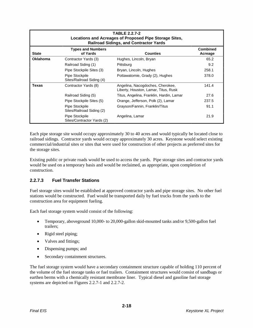
contractor yards would be required for the proposed Project. Table 2.2.7-2 provides the locations and
acreages of potential pipe storage yards and contractor yards.
TABLE 2.2.7-2 Locations and Acreages of Proposed Pipe Storage Sites,
Railroad Sidings, and Contractor Yards
State Types and Numbers
of Yards Counties Combined Acreage
Montana Contractor Yards (3) Valley, McCone, Dawson 90.6
Railroad Siding (5) Valley, Fallon, Roosevelt, Dawson (2) 100.0
Pipe Stockpile Sites (9) Phillips, Valley (2), McCone (2), Dawson (2), Fallon (2)
270.1
South Dakota Contractor Yards (5) Harding, Meade, Haakon, Jones, Tripp 150.2
Railroad Siding (5) Butte, Pennington (2), Stanley, Hutchinson 100.0
Pipe Stockpile Sites (11) Harding (3), Meade (2), Haakon (2), Jones (2), Tripp (2)
331.0
Nebraska Contractor Yards (7) Holt (2), Greeley, Merrick, York, Gage, Jefferson
213.3
Railroad Siding (3) Merrick, York, Jefferson 60.0
Pipe Stockpile Sites (8) Keya Paha, Holt (2), Greeley, Nance, Hamilton, Fillmore, Jefferson
242.3
Kansas Contractor Yards None 0
Pipe Stockpile Sites None 0
2-18 Final EIS Keystone XL Project
TABLE 2.2.7-2 Locations and Acreages of Proposed Pipe Storage Sites,
Railroad Sidings, and Contractor Yards
State Types and Numbers
of Yards Counties Combined Acreage
Oklahoma Contractor Yards (3) Hughes, Lincoln, Bryan 65.2
Railroad Siding (1) Pittsburg 9.2
Pipe Stockpile Sites (3) Bryan, Lincoln, Hughes 258.1
Pipe Stockpile Sites/Railroad Siding (4)
Pottawatomie, Grady (2), Hughes 378.0
Texas Contractor Yards (8) Angelina, Nacogdoches, Cherokee, Liberty, Houston, Lamar, Titus, Rusk
141.4
Railroad Siding (5) Titus, Angelina, Franklin, Hardin, Lamar 27.6
Pipe Stockpile Sites (5) Orange, Jefferson, Polk (2), Lamar 237.5
Pipe Stockpile Sites/Railroad Siding (2)
Grayson/Fannin, Franklin/Titus 91.1
Pipe Stockpile Sites/Contractor Yards (2)
Angelina, Lamar 21.9
Each pipe storage site would occupy approximately 30 to 40 acres and would typically be located close to
railroad sidings. Contractor yards would occupy approximately 30 acres. Keystone would select existing
commercial/industrial sites or sites that were used for construction of other projects as preferred sites for
the storage sites.
Existing public or private roads would be used to access the yards. Pipe storage sites and contractor yards
would be used on a temporary basis and would be reclaimed, as appropriate, upon completion of
construction.
2.2.7.3 Fuel Transfer Stations
Fuel storage sites would be established at approved contractor yards and pipe storage sites. No other fuel
stations would be constructed. Fuel would be transported daily by fuel trucks from the yards to the
construction area for equipment fueling.
Each fuel storage system would consist of the following:
Temporary, aboveground 10,000- to 20,000-gallon skid-mounted tanks and/or 9,500-gallon fuel trailers;
Rigid steel piping;
Valves and fittings;
Dispensing pumps; and
Secondary containment structures.
The fuel storage system would have a secondary containment structure capable of holding 110 percent of
the volume of the fuel storage tanks or fuel trailers. Containment structures would consist of sandbags or
earthen berms with a chemically resistant membrane liner. Typical diesel and gasoline fuel storage
systems are depicted on Figures 2.2.7-1 and 2.2.7-2.
2-19 Final EIS Keystone XL Project
The total fuel storage capacity would vary from yard to yard, depending on daily fuel requirements.
Typically, a 2- to 3-day supply of fuel would be maintained in storage, resulting in a maximum volume of
approximately 30,000 gallons of fuel at each storage location.
Prior to the receiving or off-loading of fuel, the trucks and equipment would be grounded to eliminate
static electricity potential. The distributor would connect a petroleum-rated hose from the delivery tanker
to the fill line at the storage facility. The fill truck connection and fill line would consist of a cam-loc
connection followed by a block valve, rigid steel piping, tank block valve(s), and check valve(s) just
upstream of the connection to the tank. Off-loading of fuel would be accomplished by a transfer pump
powered by the delivery vehicles. For dispensing gasoline and on-road diesel fuel, the transfer pump
would be a dispensing pump with petroleum-rated hoses with automatic shut-off nozzles. The fuel
transfer pump would have an emergency shut-off at the pump and a secondary emergency shut-off at least
100 feet away.
Vehicle maintenance would be performed at the contractor yards or at existing vehicle maintenance and
repair shops.
2.2.7.4 Construction Camps
Some areas within Montana and South Dakota do not have sufficient temporary housing in the vicinity of
the proposed route to house all construction personnel working on spreads in those areas. In those remote
areas, temporary work camps would be constructed to meet the housing needs of the construction
workforce. A total of four temporary construction camps would be established: two would be in
Montana, near Nashua and Baker, and two would be in South Dakota, near Union Center and Winner (see
Figure 2.2.7-3). Depending on the final construction spread configuration and construction schedule,
additional or larger camps may be required. The number and size of camps would be determined based
on the time available to complete construction and to meet Keystone’s commercial commitments. All
construction camps would be permitted, constructed, and operated consistent with applicable county,
state, and federal regulations. The relevant regulations that would have to be complied with and the
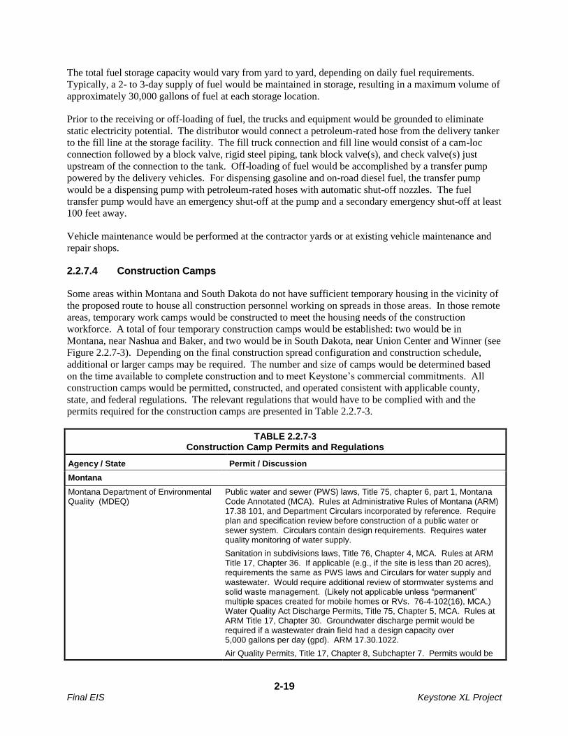
permits required for the construction camps are presented in Table 2.2.7-3.
TABLE 2.2.7-3 Construction Camp Permits and Regulations
Agency / State Permit / Discussion
Montana
Montana Department of Environmental Quality (MDEQ)
Public water and sewer (PWS) laws, Title 75, chapter 6, part 1, Montana Code Annotated (MCA). Rules at Administrative Rules of Montana (ARM) 17.38 101, and Department Circulars incorporated by reference. Require plan and specification review before construction of a public water or sewer system. Circulars contain design requirements. Requires water quality monitoring of water supply.
Sanitation in subdivisions laws, Title 76, Chapter 4, MCA. Rules at ARM Title 17, Chapter 36. If applicable (e.g., if the site is less than 20 acres), requirements the same as PWS laws and Circulars for water supply and wastewater. Would require additional review of stormwater systems and solid waste management. (Likely not applicable unless “permanent” multiple spaces created for mobile homes or RVs. 76-4-102(16), MCA.) Water Quality Act Discharge Permits, Title 75, Chapter 5, MCA. Rules at ARM Title 17, Chapter 30. Groundwater discharge permit would be required if a wastewater drain field had a design capacity over 5,000 gallons per day (gpd). ARM 17.30.1022.
Air Quality Permits, Title 17, Chapter 8, Subchapter 7. Permits would be

2-20 Final EIS Keystone XL Project
TABLE 2.2.7-3 Construction Camp Permits and Regulations
Agency / State Permit / Discussion
required for sources with potential emissions exceeding 25 tons per year (tpy) unless exemptions exist and are met for temporary non-road engines.
Department of Public Health and Human Services (DPHHS)
Work Camp licensing laws, Title 50, Chapter 52, MCA. Rules at ARM Title 37, Chapter 111, Subchapter 6. Regulations regarding water, sewer, solid waste, and food service. Incorporates MDEQ PWS requirements but has additional water and sewer provisions. Administered by DPHHS, Public Health and Safety Division, Communicable Disease Control and Prevention Bureau, Food and Consumer Safety Section.
Counties Permit required for wastewater systems, regulations adopted under Section 50-2-116(1)(k), MCA. Adopting state minimum standards promulgated by Board of Environmental Review at ARM Title 17, Chapter 36, Subchapter 9. Generally follow state laws for subdivisions, PWS, DEQ-4.
Work camp permit required in some counties.
South Dakota
South Dakota Department of Environment and Natural Resources Drinking Water Program and Surface Water Quality Program
Permit required for a Transient Non-community (TNC) PWS. There also are sampling requirements for a TNC PWS.
A National Pollution Discharge Elimination System Permit would be required for waste water discharge.
South Dakota Administrative Rules Air Quality Permit, Chapters 74:36:04-05. The diesel-fired generator engines and emergency back-up generators at each camp in South Dakota would require a minor operating permit, unless exemptions exist and are met for temporary nonroad engines.
Counties An approach permit and a building permit may be necessary in some counties.
A wide load permit is necessary for transport of modulars units to camps.
Design of Camps
Each construction camp site would be established on an approximately 80-acre site. Of that area, 30 acres
would be used as a contractor yard, and 50 acres would be used for housing and administration facilities.
The camps would be constructed using modular units and would provide the required infrastructure and
systems necessary for complete food service, housing, and personal needs, including a convenience store,
recreational and fitness facilities, entertainment rooms and facilities, telecommunications/media rooms,
kitchen/dining facilities, laundry facilities, and security units. Each camp would also have a medical
infirmary for first aid needs and to provide routine minor medical services for the workers and staff.
There would also be dedicated medical transport vehicles for both the camp sites and for the construction
ROW.
Housing facilities of the camps would consist of modular, dormitory-like units that house roughly 28
occupants per unit. The units would have heating and air conditioning systems. The camps would be set
up with the housing areas clustered together, with both shared and private wash rooms. Each camp site
would provide parking for about 100 recreational vehicles. Each camp would accommodate
approximately 600 people.
2-21 Final EIS Keystone XL Project
Potable water would be provided by drilling a well where feasible. If an adequate supply cannot be
obtained from a well, water would be obtained from municipal sources or trucked to each camp. A self-
contained wastewater treatment facility would be included in each camp except where it is practicable to
use a licensed and permitted publically owned treatment works (POTW). Wastewater treated on site
would undergo primary, secondary, and tertiary treatment consisting of solids removal, bioreactor
treatment, membrane filtration, and ultraviolet exposure. Final effluent discharge would be consistent
with all applicable regulatory requirements. If a POTW is used, Keystone would either pipe or truck
wastewater to the treatment facility.
Electricity for the camps would either be generated on site through diesel-fired generators, or would be
provided by local utilities from an interconnection to their distribution system. Keystone would contract
with a camp supplier that would provide security 24 hours per day, 7 days per week at each camp.
Keystone would work with the supplier to ensure that as many local employees are hired as possible to
staff the camps.
Use of Camps
The camps are planned to service the needs of the proposed Project work force. As a result, the
dormitories do not include facilities for families. However, workers using the recreational vehicle areas
may include family members.
Most of the workers would be transported to and from the ROW each day by buses. In addition, there
would be individual crews and workers that, due to the nature of their work, would be transported to and
from job sites by utility trucks or by welding rigs. There would also be support workers such as
mechanics, parts and supply staff, and supervisory personnel that would drive to the ROW in separate
vehicles.
Based on the current construction schedule, the camps would operate in standby mode during the winter
(from December through March or April). Each camp would have sufficient staff to operate and secure
the camp plant and systems during that time period.
Decommissioning of Camps
Decommissioning would be accomplished in two stages. First, all infrastructure systems would be
removed and either hauled away for re-use, recycled, or disposed of in accordance with regulatory
requirements. Each site would then be restored and reclaimed in accordance with permit requirements
and the applicable procedures described in Keystone’s CMR Plan (Appendix B).
2.2.7.5 Access Roads
Development of Access Roads
Existing public and private roads would be used to provide access to most of the construction ROW.
Paved roads would not likely require improvement or maintenance prior to or during construction.
However, the road infrastructure would be inspected prior to construction to ensure that the roads, bridges
and cattle guards would be able to withstand oversized vehicle use during construction. Gravel roads and
dirt roads may require maintenance during the construction period due to high use. Road improvements
such as blading and filling would generally be restricted to the existing road footprint; however, some
roads may require widening in some areas.

2-22 Final EIS Keystone XL Project
To the extent Keystone is required to conduct maintenance of any county roads, it would be done
pursuant to an agreement with the applicable county. In the event that oversized or overweight loads
would be needed to transport construction materials to the proposed Project work sites, Keystone would
submit required permit applications to the appropriate state regulatory agencies.
Approximately 400 temporary access roads would be needed to provide adequate access to the
construction sites. Private roads and any new temporary access roads would be used and maintained only
with permission of the landowner or the appropriate land management agency. Keystone would also
construct short permanent access roads from public roads to the tank farm, pump stations, delivery
facilities, and intermediate MLVs. Approximately 50 permanent access roads would be needed.
The final locations of new permanent access roads would be determined prior to construction. At a
minimum, construction of new permanent access roads would require completion of cultural resources
and biological surveys and consultations and approvals of the appropriate SHPO and USFWS office.
Other state and local permits also could also be required prior to construction. Maintenance of newly
created access roads would be the responsibility of Keystone as described below.
The acreages of access roads are included in the listing of lands affected in Table 2.1.4-1. Access road
temporary and permanent disturbance estimates are based on the 30-foot roadway width required to
accommodate oversized vehicles. In developing the acreages of disturbance, all non-public roads were
conservatively estimated to require upgrades and maintenance during construction.
Roadway Maintenance, Repair, and Safety
There were many comments on the draft EIS concerning the maintenance and repair of road surfaces used
during construction and operation of the proposed Project, as well as comments expressing concern about
roadway safety. If the proposed Project receives all permits and approvals, Keystone would work with
state and local road officials, the pipeline construction contractor, and a third-party road consultant to
identify routes that would be used for moving materials and equipment between storage and work yards to
the pipeline, valve, and pump station construction sites. When these routes are mutually agreed upon, the
road consultant would document the existing conditions of roads, including a video record. When
construction is completed, the same parties would review the road conditions, and Keystone would restore
the roads to their preconstruction condition or better. This restoration would be paid for by Keystone.
Keystone would also perform a preliminary evaluation to determine the design-rated capacity of bridges
anticipated to be used during construction and would inspect all bridges it intends to use prior to
construction and confirm that the capacity of the bridges is adequate for the anticipated weights. In cases
where the bridges are not adequate to handle the maximum weight, an alternate route would be used.
Keystone would also inspect cattle guard crossings prior to their use. If they are determined to be
inadequate to handle anticipated construction traffic, Keystone may place mats on crossings, establish an
alternate crossing, enhance existing structures, or install new infrastructure with the landowner’s
approval. All such actions would be paid for by Keystone.
During construction, Keystone and the pipeline contractor would maintain roads used for construction in
a condition that is safe for both the public and work force. Local road officials would be actively engaged
in the routine assessment of road conditions.
Keystone would follow all federal, state, and local safety plans and signage as set forth in current
Manuals of Uniform Traffic Control for streets and highways, or in similar documents issued by
regulatory agencies along the proposed route. This would include compliance with all state and local
permits pertaining to road and crossing infrastructure usage.
2-23 Final EIS Keystone XL Project
Keystone would require that each construction contractor submit a road use plan prior to mobilization,
coordinate with the appropriate state and county representatives to develop a mutually acceptable plan,
and obtain all necessary road use permits. The road use plans would identify potential scenarios that may
occur during construction based on surrounding land use, known recreational activities, and seasonal
influences (such as farming), and would establish measures to reduce or avoid effects to local
communities. Keystone would also have inspection personnel monitor road use activities to ensure that
the construction contractors comply with the road use plans and stipulations of the road.
Commenters also expressed concern that some counties in Montana stipulate that a private individual
conducting maintenance of a county road becomes liable for the safety of traffic on the road. Keystone
has stated that to the extent it is required to conduct maintenance of any county road in Montana, it would
be done pursuant to an agreement with the applicable county, and such agreement would address potential
liability, including appropriate indemnity and insurance provisions. Further, Keystone has the necessary
insurance coverage to address such potential liability.
2.3 PIPELINE SYSTEM DESIGN AND CONSTRUCTION PROCEDURES
Many commenters expressed concerns about the safety of the proposed Project, the use of industry
standards in the design of the proposed Project, and the inspection and monitoring procedures that would
be conducted. The USDOT’s Pipeline and Hazardous Materials Administration (PHMSA) is responsible
for protecting the American public and the environment by ensuring the safe and secure movement of
hazardous materials to industry and consumers by all transportation modes, including the nation’s
pipelines. Through PHMSA, the USDOT develops and enforces regulations for the safe, reliable, and
environmentally sound operation of the nation’s 2.3-million-mile pipeline transportation system and the
nearly 1 million daily shipments of hazardous materials by land, sea, and air. Within PHMSA, the Office
of Pipeline Safety (OPS) has the safety authority for the nation’s natural gas and hazardous liquid
pipelines. The proposed Project is included in the latter category.
As described below, to protect the public and environmental resources, Keystone would be required to
construct, operate, maintain, inspect, and monitor the Project consistent with the PHMSA requirements
presented in 49 CFR 195 (Transportation of Hazardous Liquids by Pipeline), as well as relevant industry
standards, and applicable state standards. These regulations specify pipeline material and qualification
standards, minimum design requirements, and required measures to protect the pipeline from internal,
external, and atmospheric corrosion. The regulations are designed to prevent crude oil pipeline accidents
and to ensure adequate protection for the public.
In addition, Keystone would comply with a set of 57 Special Conditions developed by PHMSA for the
proposed Project (see Appendix U). Originally, PHMSA began development of these conditions in
consideration of a special permit request from Keystone that, if granted, would have allowed Keystone to
operate the Project at a maximum operating pressure higher than would be allowed using the specified
design factor in 49 CFR 195.106. On August 5, 2010, Keystone withdrew its application to PHMSA for a
special permit. However, DOS continued to work with PHMSA to develop Special Conditions in
response to comments received about pipeline construction, operation, and maintenance. Keystone
agreed to incorporate the Special Conditions into the proposed Project and would include those conditions
in its manual for operations, maintenance, and emergencies that is required by 49 CFR 195.402. PHMSA
has the legal authority to inspect and enforce any items contained in a pipeline operator’s operations,
maintenance, and emergencies manual, and would therefore have the legal authority to inspect and
enforce the 57 Special Conditions if the proposed Project is approved. DOS, in consultation with
PHMSA, has determined that incorporation of those conditions would result in a Project that would
have a degree of safety over any other typically constructed domestic oil pipeline system under current

2-24 Final EIS Keystone XL Project
code and a degree of safety along the entire length of the pipeline system similar to that which is required
in High Consequence Areas (HCAs) as defined in 49 CFR 195.450.
Several commenters have recommended that the pipeline be constructed above ground. While it would
be technically feasible to construct the pipeline aboveground in most areas along the proposed route, there
are many disadvantages to an aboveground pipeline. In comparison to an aboveground pipeline, burying
a pipeline reduces the potential for pipeline damage due to vandalism, sabotage, and the effects of other
outside forces, such as vehicle collisions. Further, there has been increased concern about homeland
security since the September 11, 2001 attacks, and burying the pipeline provides a higher level of
security. Further, an above ground pipeline would be more susceptible to the effects of ambient
temperature, wind, and other storm events. Construction of an aboveground pipeline would also require
exposing the pipeline above rivers (e.g., hung from a bridge or constructed as a special pipeline span) and
roadways where it would be more accessible to those intent on damaging the pipeline.
Nearly all petroleum pipelines in the U.S. are buried, and Keystone has also proposed to bury the
proposed Project pipeline. As described above, the facilities would be designed, constructed, tested, and
operated in accordance with the regulations in 49 CFR 195, the 57 Special Conditions provided to
Keystone by PHMSA, and all other applicable federal and state regulations.
If the proposed Project is approved and implemented, PHMSA would maintain continual regulatory
oversight over the Project, throughout construction, testing, start-up, operation, and maintenance. The
PHMSA regulations presented in 49 CFR 195 Transportation of Hazardous Liquids by Pipeline specify
pipeline material and qualification standards, minimum design requirements, and required measures to
protect the pipeline from internal, external, and atmospheric corrosion. The regulations are designed to
prevent crude oil pipeline accidents and to ensure adequate protection for the public. Section 2.3.1
presents the major pipeline design considerations of the proposed Project. In addition, the Special
Conditions provide more stringent requirements for many of these design factors.
Keystone prepared a draft CMR Plan that was included in Appendix B of the draft EIS. That plan
described the construction methods and environmental protection measures that Keystone committed to in
order to reduce the potential construction impacts of the proposed Project. The CMR Plan was revised
after the publication of the draft EIS to update the procedures based on agency reviews and input. The
current version of the plan is presented in Appendix B. If the proposed Project is issued a Presidential
Permit, the CMR Plan would be updated after the ROD is issued to reflect any additional conditions
included in the ROD and in other permits issued to Keystone, and to reflect regional construction
considerations.
Prior to pipeline construction, Keystone would prepare a Spill Prevention, Control, and Countermeasure
(SPCC) Plan to avoid or minimize the potential for harmful spills and leaks during construction. A draft
version of the SPCC submitted by Keystone is included in Appendix C.
EPA submitted a comment expressing concern that the non-transportation related equipment and activities
at pump stations, breakout tanks, and the tank farm may require the submission and some cases, approval,
of a Facility Response Plan (FRP) as required under 40 CFR 112.20. However, it appears unlikely that
the proposed Project would be required to submit an FRP under 40 CFR 112.20 for equipment and
activities at the pump stations, the Cushing tank farm, or the surge relief tanks at the Nederland delivery
point. Those facilities would not house any non-transportation-related equipment or activities subject to
the requirement to prepare and submit an FRP. Further, 40 CFR 112.20 requires an FRP if a facility
could reasonably be expected to cause substantive harm to the environment by discharging oil into or on
the navigable waters or adjoining shorelines. However, if EPA makes the determination that any or all of
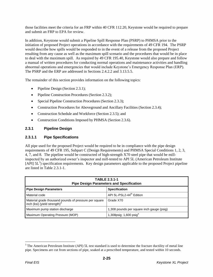
2-25 Final EIS Keystone XL Project
those facilities meet the criteria for an FRP within 40 CFR 112.20, Keystone would be required to prepare
and submit an FRP to EPA for review.
In addition, Keystone would submit a Pipeline Spill Response Plan (PSRP) to PHMSA prior to the
initiation of proposed Project operations in accordance with the requirements of 49 CFR 194. The PSRP
would describe how spills would be responded to in the event of a release from the proposed Project
resulting from any cause as well as the maximum spill scenario and the procedures that would be in place
to deal with the maximum spill. As required by 49 CFR 195.40, Keystone would also prepare and follow
a manual of written procedures for conducting normal operations and maintenance activities and handling
abnormal operations and emergencies that would include Keystone’s Emergency Response Plan (ERP).
The PSRP and the ERP are addressed in Sections 2.4.2.2 and 3.13.5.5.
The remainder of this section provides information on the following topics:
Pipeline Design (Section 2.3.1);
Pipeline Construction Procedures (Section 2.3.2);
Special Pipeline Construction Procedures (Section 2.3.3);
Construction Procedures for Aboveground and Ancillary Facilities (Section 2.3.4);
Construction Schedule and Workforce (Section 2.3.5); and
Construction Conditions Imposed by PHMSA (Section 2.3.6).
2.3.1 Pipeline Design
2.3.1.1 Pipe Specifications
All pipe used for the proposed Project would be required to be in compliance with the pipe design
requirements of 49 CFR 195, Subpart C (Design Requirements) and PHMSA Special Conditions 1, 2, 3,
4, 7, and 8. The pipeline would be constructed of high-strength X70 steel pipe that would be mill-
inspected by an authorized owner’s inspector and mill-tested to API 5L (American Petroleum Institute
[API] 5L3) specification requirements. Key design parameters applicable to the proposed Project pipeline
are listed in Table 2.3.1-1.
TABLE 2.3.1-1 Pipe Design Parameters and Specification
Pipe Design Parameters Specification
Material code API 5L-PSL2-44th
Edition
Material grade thousand pounds of pressure per square inch (ksi) (yield strength)
a
Grade X70
Maximum pump station discharge 1,308 pounds per square inch gauge (psig)
Maximum Operating Pressure (MOP) 1,308psig; 1,600 psiga
3 The American Petroleum Institute (API) 5L test standard is used to determine the fracture ductility of metal line
pipe. Specimens are cut from sections of pipe, soaked at a prescribed temperature, and tested within 10 seconds.
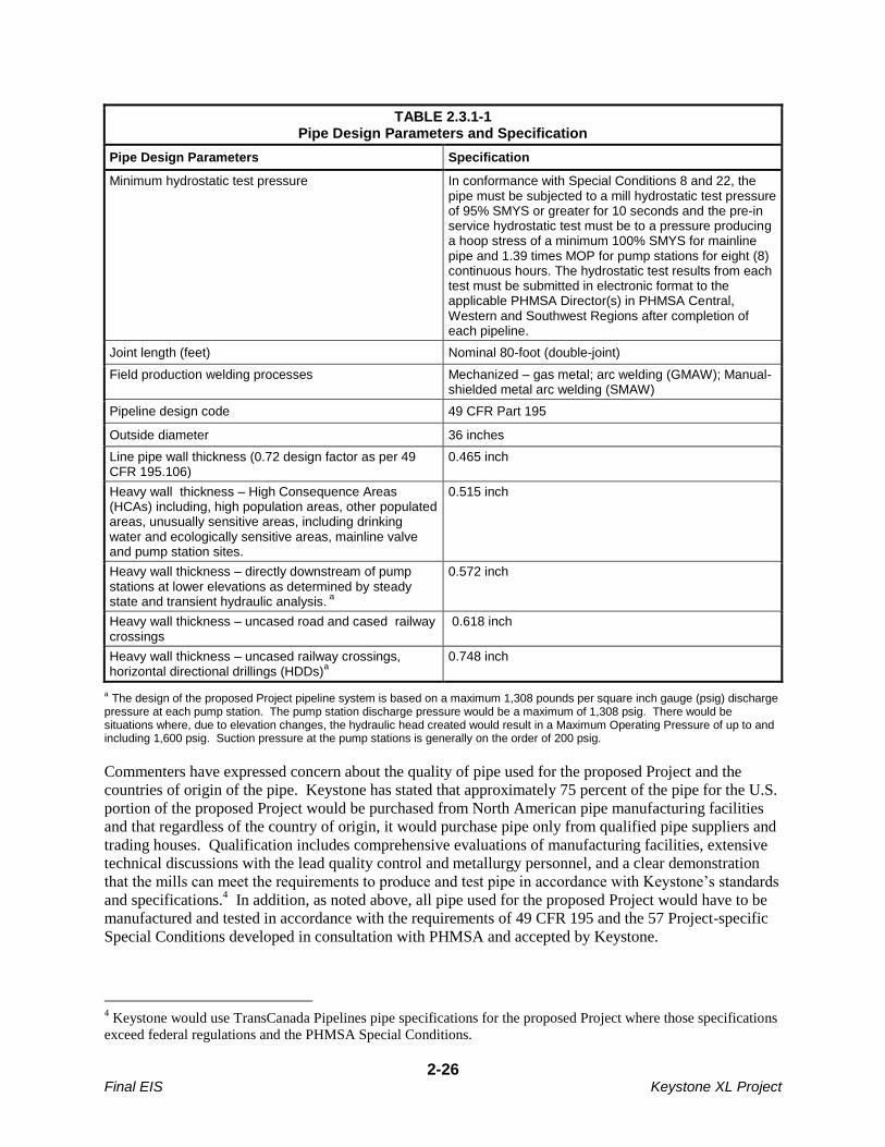
2-26 Final EIS Keystone XL Project
TABLE 2.3.1-1 Pipe Design Parameters and Specification
Pipe Design Parameters Specification
Minimum hydrostatic test pressure In conformance with Special Conditions 8 and 22, the pipe must be subjected to a mill hydrostatic test pressure of 95% SMYS or greater for 10 seconds and the pre-in service hydrostatic test must be to a pressure producing a hoop stress of a minimum 100% SMYS for mainline pipe and 1.39 times MOP for pump stations for eight (8) continuous hours. The hydrostatic test results from each test must be submitted in electronic format to the applicable PHMSA Director(s) in PHMSA Central, Western and Southwest Regions after completion of each pipeline.
Joint length (feet) Nominal 80-foot (double-joint)
Field production welding processes Mechanized – gas metal; arc welding (GMAW); Manual- shielded metal arc welding (SMAW)
Pipeline design code 49 CFR Part 195
Outside diameter 36 inches
Line pipe wall thickness (0.72 design factor as per 49 CFR 195.106)
0.465 inch
Heavy wall thickness – High Consequence Areas (HCAs) including, high population areas, other populated areas, unusually sensitive areas, including drinking water and ecologically sensitive areas, mainline valve and pump station sites.
0.515 inch
Heavy wall thickness – directly downstream of pump stations at lower elevations as determined by steady state and transient hydraulic analysis.
a
0.572 inch
Heavy wall thickness – uncased road and cased railway crossings
0.618 inch
Heavy wall thickness – uncased railway crossings, horizontal directional drillings (HDDs)
a
0.748 inch
a The design of the proposed Project pipeline system is based on a maximum 1,308 pounds per square inch gauge (psig) discharge pressure at each pump station. The pump station discharge pressure would be a maximum of 1,308 psig. There would be situations where, due to elevation changes, the hydraulic head created would result in a Maximum Operating Pressure of up to and including 1,600 psig. Suction pressure at the pump stations is generally on the order of 200 psig.
Commenters have expressed concern about the quality of pipe used for the proposed Project and the
countries of origin of the pipe. Keystone has stated that approximately 75 percent of the pipe for the U.S.
portion of the proposed Project would be purchased from North American pipe manufacturing facilities
and that regardless of the country of origin, it would purchase pipe only from qualified pipe suppliers and
trading houses. Qualification includes comprehensive evaluations of manufacturing facilities, extensive
technical discussions with the lead quality control and metallurgy personnel, and a clear demonstration
that the mills can meet the requirements to produce and test pipe in accordance with Keystone’s standards
and specifications.4 In addition, as noted above, all pipe used for the proposed Project would have to be
manufactured and tested in accordance with the requirements of 49 CFR 195 and the 57 Project-specific
Special Conditions developed in consultation with PHMSA and accepted by Keystone.
4 Keystone would use TransCanada Pipelines pipe specifications for the proposed Project where those specifications
exceed federal regulations and the PHMSA Special Conditions.
2-27 Final EIS Keystone XL Project
Keystone would review, and if appropriate, approve the pipe manufacturer’s procedure specifications
prior to the pipe mill initiating purchase or production of steel to ensure the material meets the API 5L
Line Pipe Specification and Keystone’s Corporate Specifications and Project-specific requirements.
Surveillance personnel would be stationed in the pipe mill through the duration of production to inspect
the finished pipe and monitor compliance to the specifications throughout the manufacturing process.
These personnel would monitor things such as mill test reports and other appropriate documentation,
including production logs, steel quality, fabrication, welding rejection summaries, lab results, and non-
conformance reports.
TransCanada’s pipe manufacturing specifications also specify that any deviation in the rolling process
requires testing to be recommenced from the point of deviation to ensure uniformity. Finally, additional
mechanical and chemical property tests based on steel grade, plate, and/or coil would be completed based
on the steel manufacturing process as well as rolling and cooling temperatures. Those tests ensure that
steel properties are not variable.
2.3.1.2 External Corrosion Protection
To protect against corrosion, an external coating (fusion-bonded epoxy, or FBE) would be applied to the
pipeline and all buried facilities, and cathodic protection (CP) would be applied to the pipeline by
impressed current. These measures would be provided in compliance with 49 CFR Part 195, Subpart H
(Corrosion Control) and the requirements of 14 of the PHMSA 57 Special Conditions (see Appendix U).
The primary impressed current CP systems would be rectifiers coupled to semi-deep vertical anode beds
at each pump station, as well as rectifiers coupled to deep-well anode beds at selected intermediate
mainline valve sites. The rectifiers would be variable output transformers which would convert incoming
AC power to DC voltage and current to provide the necessary current density to the CP design structures.
The rectifiers would have a negative cable connection to the design structure and a positive cable
connection to the anode beds. The anode beds would consist of high silicon cast iron anodes backfilled
with a highly conductive coke powder to allow for an expected anode minimum life of 20 years. During
operation, the CP system would be monitored and remediation performed to prolong the anode bed and
systems. The semi-deep anode beds would be 12-inch-diameter vertical holes spaced 15 feet apart with a
bottom hole depth of approximately 45 feet. The deep-well anode bed would be a single 12-inch-
diameter vertical hole with a bottom hole depth of approximately 300 feet.
2.3.2 Pipeline Construction Procedures
Once engineering surveys of the ROW centerline and additional temporary workspace areas have been
finalized, and the acquisition of ROW easements and any necessary acquisitions of property in fee have
been completed, construction would begin. Several commenters have expressed concern about the
negotiation process for easement agreements along the proposed route and the use of eminent domain for
the procurement of some easements. Commenters have also suggested that the applicant is a Canadian
company and should not be allowed to use the eminent domain process to obtain easements. In addition,
some commenters have expressed concern about their options if Keystone does not comply with easement
agreements.
Keystone is a U.S. corporation that was incorporated in accordance with the laws of the State of
Delaware. Keystone is the corporate entity that will construct the pipeline if it is approved. Keystone is
therefore eligible to use eminent domain laws. To construct, operate, and maintain the proposed Project,
Keystone would need the rights to easements along the entire proposed route. Keystone is responsible for
negotiating easement agreements with landowners along the route in each state. The easement
agreements would list the conditions that both the landowner and Keystone agree to, including financial
compensation to the landowners in return for granting easements. Compensation would also be made for
2-28 Final EIS Keystone XL Project
loss of use during construction, crop loss, loss of non-renewable or other resources, and restoration of any
unavoidable damage to personal property during construction. DOS expects Keystone to negotiate fairly,
honestly, and respectfully with landowners when they negotiate an easement. However, those
negotiations and final agreements are private business concerns between the landowners and Keystone,
and DOS has no legal authority or ability to intervene in the proceedings.
If Keystone obtains all necessary permits and approvals and an easement negotiation cannot be completed
in a manner suitable to both parties, Keystone would use state eminent domain laws to obtain easements
needed for pipeline construction, maintenance, and operation. State laws dictate under what
circumstances eminent domain may be used and define the eminent domain process within the state. The
level of compensation would be determined by a court according to applicable state law. Again, DOS has
no legal authority or ability to intervene in eminent domain proceedings. In addition, eminent domain
does not apply to land under federal ownership or management.
State or local trespass and access laws are applicable along the entire route and therefore along each
easement negotiated by Keystone and the landowner or obtained by Keystone through the eminent
domain process. As noted above, DOS has no legal authority over negotiating easement agreements and
has no legal status to enforce the conditions of an easement agreement. A landowner who considers
Keystone to be out of compliance with an easement agreement would have take up the matter with
Keystone or local law enforcement officials, or initiate legal consultation.
As proposed, the pipeline would be constructed in 17 spreads. Final spread configurations and the final
construction schedule may result in the use of additional spreads or fewer shorter or longer spreads.
Figure 2.3.2-1 depicts the approximate location of each spread. The 851.6-mile-long Steele City Segment
would be constructed using 10 mainline spreads from approximately 63 to 109 miles long. Construction
of the 483.8-mile-long Gulf Coast Segment pipeline would be accomplished using 6 spreads from about
49 to 100 miles in length. The 48.6-mile-long Houston Lateral would be constructed using one spread.
Pipeline construction would generally proceed as a moving assembly line composed of specific activities
including surveying and staking of the ROW, clearing and grading, pipe stringing, bending, trenching,
welding, installing, backfilling, hydrostatic testing, and cleanup, as described in the subsections below
and illustrated in Figure 2.3.2-2. In addition, special construction techniques would be used for specific
site conditions such as rugged terrain, waterbodies, wetlands, paved roads, highways, and railroads.
These non-standard pipeline construction procedures are described in Section 2.3.3.
On the Steele City Segment, construction is planned to continue into the early winter months for as long
as the weather permits construction without the use of special winter construction techniques. However,
as stated in the CMR Plan (Appendix B), if the proposed Project is authorized and winter construction is
necessary to meet construction deadlines, Keystone would consult with the relevant federal, state, and
local regulatory agencies to determine what changes may be necessary in permits issued, what additional
permits may be required, and to identify the procedures that would have to be incorporated into
construction to avoid or minimize environmental impacts. Winter construction plans would be finalized
based on those consultations and permit requirements. On the Gulf Coast Segment and the Houston
Lateral, although construction is planned for winter months, the prevailing climate would not require the
use of special winter construction techniques.
A list of typical equipment to be used during construction is presented in Table 2.3.2-1. Actual
equipment used would depend on the construction activity and specific equipment owned or leased by the
construction contractors selected.
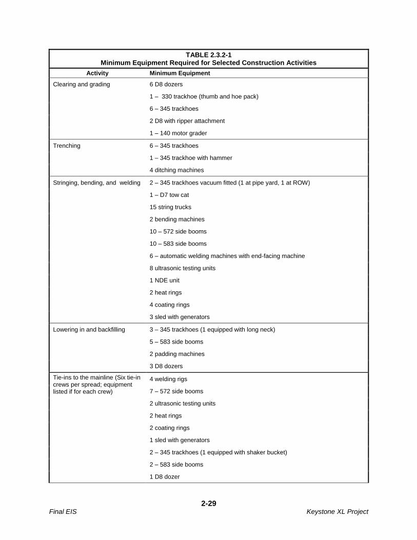
2-29 Final EIS Keystone XL Project
TABLE 2.3.2-1 Minimum Equipment Required for Selected Construction Activities
Activity Minimum Equipment
Clearing and grading 6 D8 dozers
1 – 330 trackhoe (thumb and hoe pack)
6 – 345 trackhoes
2 D8 with ripper attachment
1 – 140 motor grader
Trenching 6 – 345 trackhoes
1 – 345 trackhoe with hammer
4 ditching machines
Stringing, bending, and welding 2 – 345 trackhoes vacuum fitted (1 at pipe yard, 1 at ROW)
1 – D7 tow cat
15 string trucks
2 bending machines
10 – 572 side booms
10 – 583 side booms
6 – automatic welding machines with end-facing machine
8 ultrasonic testing units
1 NDE unit
2 heat rings
4 coating rings
3 sled with generators
Lowering in and backfilling 3 – 345 trackhoes (1 equipped with long neck)
5 – 583 side booms
2 padding machines
3 D8 dozers
Tie-ins to the mainline (Six tie-in crews per spread; equipment listed if for each crew)
4 welding rigs
7 – 572 side booms
2 ultrasonic testing units
2 heat rings
2 coating rings
1 sled with generators
2 – 345 trackhoes (1 equipped with shaker bucket)
2 – 583 side booms
1 D8 dozer
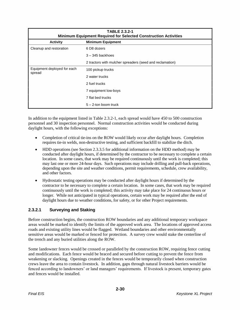
2-30 Final EIS Keystone XL Project
TABLE 2.3.2-1 Minimum Equipment Required for Selected Construction Activities
Activity Minimum Equipment
Cleanup and restoration 6 D8 dozers
3 – 345 backhoes
2 tractors with mulcher spreaders (seed and reclamation)
Equipment deployed for each spread
100 pickup trucks
2 water trucks
2 fuel trucks
7 equipment low-boys
7 flat bed trucks
5 – 2-ton boom truck
In addition to the equipment listed in Table 2.3.2-1, each spread would have 450 to 500 construction
personnel and 30 inspection personnel. Normal construction activities would be conducted during
daylight hours, with the following exceptions:
Completion of critical tie-ins on the ROW would likely occur after daylight hours. Completion requires tie-in welds, non-destructive testing, and sufficient backfill to stabilize the ditch.
HDD operations (see Section 2.3.3.5 for additional information on the HDD method) may be conducted after daylight hours, if determined by the contractor to be necessary to complete a certain location. In some cases, that work may be required continuously until the work is completed; this may last one or more 24-hour days. Such operations may include drilling and pull-back operations, depending upon the site and weather conditions, permit requirements, schedule, crew availability, and other factors.
Hydrostatic testing operations may be conducted after daylight hours if determined by the
contractor to be necessary to complete a certain location. In some cases, that work may be required
continuously until the work is completed; this activity may take place for 24 continuous hours or
longer. While not anticipated in typical operations, certain work may be required after the end of
daylight hours due to weather conditions, for safety, or for other Project requirements.
2.3.2.1 Surveying and Staking
Before construction begins, the construction ROW boundaries and any additional temporary workspace
areas would be marked to identify the limits of the approved work area. The locations of approved access
roads and existing utility lines would be flagged. Wetland boundaries and other environmentally
sensitive areas would be marked or fenced for protection. A survey crew would stake the centerline of
the trench and any buried utilities along the ROW.
Some landowner fences would be crossed or paralleled by the construction ROW, requiring fence cutting
and modifications. Each fence would be braced and secured before cutting to prevent the fence from
weakening or slacking. Openings created in the fences would be temporarily closed when construction
crews leave the area to contain livestock. In addition, gaps through natural livestock barriers would be
fenced according to landowners’ or land managers’ requirements. If livestock is present, temporary gates
and fences would be installed.
2-31 Final EIS Keystone XL Project
2.3.2.2 Clearing and Grading
Prior to vegetation removal along slopes leading to wetlands and riparian areas, temporary erosion control
measures such as silt fences or straw bales would be installed. The work area would be cleared of
vegetation, including crops and obstacles such as trees, logs, brush, or rocks.
Grading would be performed where necessary to provide a reasonably level work surface or where required by landowners or land managers. Where the ground is relatively flat and does not require grading, rootstock would be left in the ground. More extensive grading would be required in steep slope areas to safely construct the pipeline along ROW. Where grading occurs and topsoil is present, topsoil would be removed from the entire area to be graded and stored separately from the subsoil.
2.3.2.3 Trenching
Trenching may be carried out before or after stringing, bending and welding (see Section 2.3.2.4)
depending upon several factors such as soil characteristics, water table, presence of drain tiles, and
weather conditions at the time of construction.
In areas of rocky soils or bedrock, tractor-mounted mechanical rippers or rock trenchers would fracture
the rock prior to excavation. In areas where topsoil segregation would be required, the actual depth of
topsoil would be removed up to a maximum depth of 12 inches and segregated. In most areas where soil
would be removed from only the trench, topsoil would be piled on the near-side of the trench and subsoil
on the far side of the trench. A “triple lift” method would be used in areas where deep soils would be
excavated, primarily over the pipeline trench in cultivated fields to minimize impacts to agricultural
production. This method would involve stockpiling three different soil horizons, including the topsoil
horizon, as described in Section 3.2.2.1. This separation of topsoil from subsoil would allow for proper
restoration of the soil during the backfilling process. Where soil is removed from both the trench and the
spoil side, topsoil would be stored on the near-side of the construction ROW edge, and the subsoil on the
spoil-side of the trench.
These procedures separating topsoil would reduce the potential for mixing of subsoil and topsoil. In addition, the spoil piles would be spaced to accommodate storm water runoff. Typical soil separation methods are illustrated in Figures 2.1.2-1 through 2.1.2-3.
On agricultural land, rocks that are exposed on the surface due to construction activity would be removed
from the ROW prior to and after topsoil replacement. Rock removal would also occur in rangeland to
ensure that the productive capability of the land is maintained. In some landscapes, thin soils overlay
bedrock, or exposed bedrock exists at the surface. In these cases, rock would be replaced to the extent
practicable. Clearing of rocks could be carried out either manually or with a mechanical rock picker and
topsoil would be preserved. Rocks that are similar in size to those occurring in the undisturbed landscape
would be left in place to the extent practicable. Rock removed from the ROW would be either hauled
away for disposal in appropriate facilities or placed in a location acceptable to the landowner.
Trench excavation would typically be to depths of between 7 and 8 feet, with a trench width of
approximately 4 to 5 feet. In most areas, there would be a minimum of 4 feet of cover over the pipeline
after backfilling. The depth of burial would be consistent with PHMSA Special Condition 19 which
states the following:
“19) Depth of Cover: Keystone shall construct the pipeline with soil cover at a minimum depth of
forty-eight (48) inches in all areas, except in consolidated rock. The minimum depth in
consolidated rock areas is thirty-six (36) inches.”
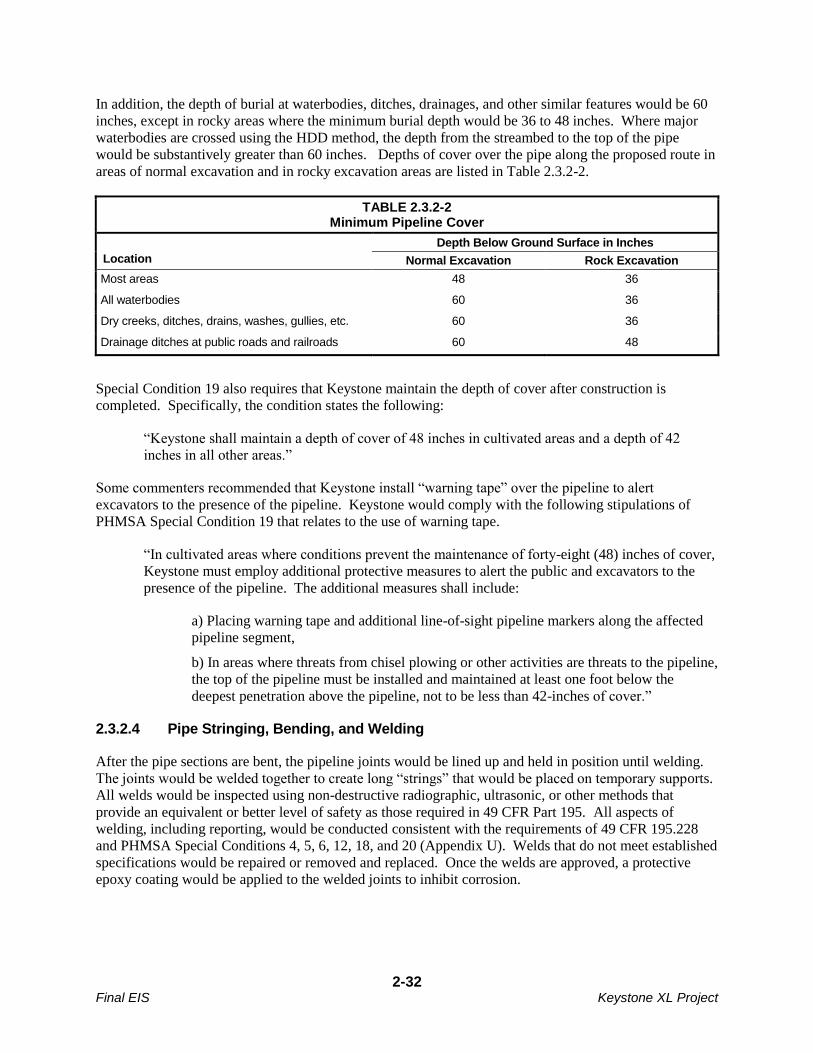
2-32 Final EIS Keystone XL Project
In addition, the depth of burial at waterbodies, ditches, drainages, and other similar features would be 60
inches, except in rocky areas where the minimum burial depth would be 36 to 48 inches. Where major
waterbodies are crossed using the HDD method, the depth from the streambed to the top of the pipe
would be substantively greater than 60 inches. Depths of cover over the pipe along the proposed route in
areas of normal excavation and in rocky excavation areas are listed in Table 2.3.2-2.
TABLE 2.3.2-2 Minimum Pipeline Cover
Depth Below Ground Surface in Inches
Location Normal Excavation Rock Excavation
Most areas 48 36
All waterbodies 60 36
Dry creeks, ditches, drains, washes, gullies, etc. 60 36
Drainage ditches at public roads and railroads 60 48
Special Condition 19 also requires that Keystone maintain the depth of cover after construction is
completed. Specifically, the condition states the following:
“Keystone shall maintain a depth of cover of 48 inches in cultivated areas and a depth of 42
inches in all other areas.”
Some commenters recommended that Keystone install “warning tape” over the pipeline to alert
excavators to the presence of the pipeline. Keystone would comply with the following stipulations of
PHMSA Special Condition 19 that relates to the use of warning tape.
“In cultivated areas where conditions prevent the maintenance of forty-eight (48) inches of cover,
Keystone must employ additional protective measures to alert the public and excavators to the
presence of the pipeline. The additional measures shall include:
a) Placing warning tape and additional line-of-sight pipeline markers along the affected
pipeline segment,
b) In areas where threats from chisel plowing or other activities are threats to the pipeline,
the top of the pipeline must be installed and maintained at least one foot below the
deepest penetration above the pipeline, not to be less than 42-inches of cover.”
2.3.2.4 Pipe Stringing, Bending, and Welding
After the pipe sections are bent, the pipeline joints would be lined up and held in position until welding.
The joints would be welded together to create long “strings” that would be placed on temporary supports.
All welds would be inspected using non-destructive radiographic, ultrasonic, or other methods that
provide an equivalent or better level of safety as those required in 49 CFR Part 195. All aspects of
welding, including reporting, would be conducted consistent with the requirements of 49 CFR 195.228
and PHMSA Special Conditions 4, 5, 6, 12, 18, and 20 (Appendix U). Welds that do not meet established
specifications would be repaired or removed and replaced. Once the welds are approved, a protective
epoxy coating would be applied to the welded joints to inhibit corrosion.
2-33 Final EIS Keystone XL Project
2.3.2.5 Installing and Backfilling
Prior to installing the pipe into the trench, the trench would be cleared of rocks and debris that might
damage the pipe or the pipe coating. If water has entered the trench, dewatering may be required prior to
installation. Discharge of water from dewatering would be accomplished in accordance with applicable
discharge permits. On sloped terrain, trench breakers (e.g., stacked sand bags or foam) would be installed
in the trench at specified intervals to prevent subsurface water movement along the pipeline.
In some cases sand or gravel padding material may be placed in the bottom of the trench to protect the
pipeline from damage during installation. In no case would topsoil be used as a padding material. In
areas of rocky soils or bedrock, the bottom of the trench would be padded with borrow material such as
sand or gravel. Where rock occurs within the trench perimeter, abrasion resistant coatings or rock shields
would be used to protect the pipe prior to installation.
The pipeline would be lowered into the trench and the trench would first be backfilled using the
excavated subsoil material. In rocky areas, excavated rock would be used to backfill the trench to the top
of the existing bedrock profile. After the initial backfilling, topsoil would be returned to its original
position over the trench.
2.3.2.6 Hydrostatic Testing
In addition to hydrostatic testing at the pipe mills, the pipeline would be cleaned and hydrostatically
tested prior to putting the pipe into service and after backfilling and all construction work that could
directly affect the pipe is complete. The testing would be conducted in pipeline sections approximately
30 to 50 miles long. Hydrostatic testing would provide assurance that the system is capable of
withstanding the maximum operating pressure and would be conducted in accordance with the regulatory
requirements of 49 CFR Part 195, Subpart E (Pressure Testing) and the stipulations in PHMSA Special
Conditions 5, 20, 22, and 23 (Appendix U). The process would be conducted as follows:
Isolate the pipe section being tested with test manifolds;
Fill the section with water;
Pressurize the section to a pressure that would produce a hoop stress of a minimum of 100
percent of the specified minimum yield strength for the mainline pipe and 1.39 times the
maximum operating pressure for pump stations; and
Maintain that pressure for a period of 8 hours.
2.3.2.7 Pipe Geometry Inspection, Final Tie-ins, and Commissioning
After hydrostatic testing is complete, the pipeline would be dewatered and inspected using an electronic
caliper (geometry) pig to check for dents or other deformations and where appropriate, pipe sections
would be replaced in accordance with the requirements of 49 CFR 195 and the Special Conditions in
Appendix U. The final pipeline tie-ins would then be welded and inspected.
After the final tie-ins are complete and inspected, the pipeline would be commissioned through the
verification of proper installation and function of the pipeline and appurtenant systems, including control
and communication equipment, based on the requirements of 49 CFR 195 and the relevant PHMSA
Special Conditions.
2-34 Final EIS Keystone XL Project
2.3.2.8 Cleanup and Restoration
Cleanup would include the removal of construction debris, final contouring, and installation of erosion
control features. The cleanup process would begin as soon as possible after backfilling but the timing
would be dependent on weather conditions. Preliminary cleanup would be completed within
approximately 20 days after the completion of backfilling assuming appropriate weather conditions
prevail. Removed construction debris would be disposed in existing, permitted disposal facilities in
accordance with relevant federal, state, and local regulations.
Reseeding of the ROW would occur as soon as possible after completion of cleanup to stabilize soil.
Procedures would depend on weather and soil conditions and would follow recommended rates and seed
mixes provided by the landowner, the land management agency, or the NRCS. Access to the permanent
easement would be restricted using gates, boulders, or other barriers to minimize unauthorized access by
all-terrain vehicles, if requested by the landowner.
All existing fencing and grazing structures, such as fences, gates, irrigation ditches, cattle guards, and
reservoirs would be repaired to pre-construction conditions or better upon completion of construction
activities.
Pipeline markers would be provided for identification of the pipeline location for safety purposes in
accordance with the requirements of 49 CFR 195.410 (Line Markers) and PHMSA Project-specific
Special Condition 40 (see Appendix U), including the following:
Pipeline markers would be installed on both sides of all highways, roads, road ROWs, railroads, and waterbody crossings and in areas where the pipeline is buried less than 48 inches;
Pipeline markers would be made from industrial strength materials to withstand abrasion from wind and damage from cattle;
Pipeline markers would be installed at all fences;
Pipeline markers would be installed along the ROW to provide line-of-sight marking of the pipeline, providing it is practical to do so and consistent with the type of land use, such that it does not hinder the use of the property by the landowner. Pipeline markers would be installed at all angle points, and at intermediate points, where practical, so that from any marker, the adjacent marker in either direction would be visible;
Consideration would be given to installing additional markers, except where they would interfere with land use (e.g., farming);
Aerial markers showing identifying numbers would be installed at approximately 5-mile intervals; and
At each MLV site and pump station, signs would be installed and maintained on the perimeter fence
where the pipeline enters and exits the fenced area.
Markers would identify the owner of the pipeline and convey emergency contact information. Special
markers providing information and guidance to aerial patrol pilots also would be installed. The markers
would be maintained during operating life of the proposed Project.
2.3.2.9 Post-Construction Reclamation Monitoring and Response
The ROW would be inspected after the first growing season to determine the success of revegetation and
noxious weed control. Eroded areas would be repaired and areas that were unsuccessfully re-established
would be revegetated by Keystone or Keystone would compensate the landowner for reseeding. The
2-35 Final EIS Keystone XL Project
CMR Plan (Appendix B) provides information on revegetation and weed control procedures that
Keystone would incorporate into the proposed Project.
2.3.3 Special Pipeline Construction Procedures
Special construction techniques would be used when crossing roads, highways and railroads; pipeline,
utility, and other buried feature crossings; steep terrain; unstable soils; perennial waterbodies; wetlands;
areas that require ripping; and residential and commercial areas. These special techniques are described
below.
2.3.3.1 Road, Highway, and Railroad Crossings
Construction across paved roads, highways, and railroads would be in accordance with the requirements
of the appropriate road and railroad crossing permits and approvals. In general, all major paved roads, all
primary gravel roads, all highways, and all railroads would be crossed by boring beneath the road or
railroad, as shown in Figure 2.3.3-1. Boring would result in minimal or no disruption to traffic at road or
railroad crossings. Each boring would take 1 to 2 days for most roads and railroads, and 10 days for long
crossings such as interstate or 4-lane highways.
Initially, a pit would be excavated on each side of the feature; boring equipment would be placed in the
pit and a hole would be bored under the road at least equal to the diameter of the pipe and a prefabricated
pipe section would be pulled through the borehole. For long crossings, sections would be welded onto the
pipe string before being pulled through the borehole.
If permitted by local regulators and landowners, smaller gravel roads and driveways would likely be
crossed using an open-cut method that would typically take between 1 and 2 days to complete. This
would require temporary road closures and the establishment of detours for traffic. If no reasonable
detour is feasible, at least one lane of traffic would be kept open in most cases. Keystone would post
signs at these open-cut crossings and would implement traffic control plans to reduce traffic disturbance
and protect public safety. Section 2.2.7.5 provides additional information on roadway safety,
maintenance, and repair.
2.3.3.2 Pipeline, Utility, and Other Buried Feature Crossings
Keystone and its pipeline contractors would comply with USDOT regulations, utility agreements, and
industry BMPs with respect to utility crossing and separation specifications. One-call notification would
be made for all utility crossings to identify utilities. Similarly, private landowners would be notified of
planned construction activities so that buried features, such as irrigation systems and other water lines,
could be avoided or replaced. Prior to construction, each rancher with a stock watering or irrigation
system or other water lines would be asked to provide the location of any waterlines in the construction
area. The location of these waterlines would be documented and Keystone would lower some waterlines
prior to construction. In the case of existing buried oil or gas pipelines, the owner of the facility would be
asked to provide information on the locations of pipes in the construction area. Metallic pipelines would
be physically located by a line locating crew prior to construction.
Unless otherwise specified in a crossing agreement, the contractor would excavate to allow installation of
the proposed Project pipeline across the existing pipeline or utility with a minimum clearance of 12
inches. The clearance distance would be filled with sandbags or suitable fill material to maintain the
clearance. Backfill of the crossing would be compacted in lifts to ensure continuous support of the
existing utility.
2-36 Final EIS Keystone XL Project
For some crossings, the owner of the utility or buried feature may require the facility to be excavated and
exposed by their own employees prior to the Keystone contractor getting to the location. In those cases,
Keystone would work with owners to complete work to the satisfaction of the owner. Where the owner
of the utility does not require pre-excavation, generally, the pipeline contractor would locate and expose
the utility before excavating the trench.
2.3.3.3 Steep Terrain
Steep slopes traversed by the proposed route would be graded to reduce slope angles, thus allowing safer
operation of construction equipment and reducing the degree of pipe bending required. In areas where the
pipeline route crosses side slopes, cut-and-fill grading may be employed to obtain a safe working terrace.
Prior to cut-and-fill grading on steep terrain, topsoil would be stripped from the ROW and stockpiled. If
soil and slope conditions permit, soil from the high side of the ROW would be excavated and moved to
the low side to create a safer and more level working surface. After pipeline installation, soil from the
low side of the ROW would be returned to the high side and the contour of the slope would be restored to
its pre-construction condition to the degree practicable.
Temporary sediment barriers, such as silt fences and straw bales, would be installed where appropriate to
prevent erosion and siltation of wetlands, waterbodies, or other environmentally sensitive areas. During
grading, temporary slope breakers consisting of mounded and compacted soil would be installed across
the ROW. In the cleanup phase, permanent slope breakers would be installed where appropriate. Section
4.5 of the CMR Plan (Appendix B) presents additional information on the use of sediment barriers and
slope breakers.
After regrading and installation of erosion control devices, seed would be applied to steep slopes and
mulch consisting of hay or non-brittle straw would be placed on the ROW, or the ROW would be
protected with erosion control geofabrics. Where appropriate to avoid animal entanglement, geofabric
mesh size would be 2 inches or greater. Sediment barriers would be maintained across the ROW until
permanent vegetation is established. Additional temporary workspaces may be required for storage of
graded material and/or topsoil during construction.
2.3.3.4 Unstable Soils
Special construction techniques and environmental protection measures would be applied to areas with
unstable soils, such as those within the Sand Hills region of South Dakota and Nebraska, and to areas
with high potential for landslides, erosion, and mass wasting. Construction in these areas could require
additional temporary workspace areas.
Topsoil piles would be protected from erosion through matting, mulching, watering, or tackifying to the
extent practicable. Photodegradable matting would be placed on steep slopes or areas prone to extreme
wind exposure, such as north- or west-facing slopes and ridge tops. Biodegradable pins would be used in
place of metal staples to hold the matting in place.
Reseeding would be carried out using native seed mixes that are certified noxious weed-free, if possible.
Land imprinting may be employed to create impressions in the soil to reduce erosion, improve moisture
retention, and create micro-sites for seed germination. Keystone would work with landowners to evaluate
fencing the ROW from livestock, or alternatively, to provide compensation if a pasture needs to be rested
until vegetation can become established.

2-37 Final EIS Keystone XL Project
2.3.3.5 Waterbody Crossings
In the final design phase of the proposed Project, perennial waterbody crossings for the proposed pipeline
would be assessed by qualified personnel with respect to the potential for channel aggradation or
degradation and lateral channel migration. The level of assessment for each crossing would vary based
on the professional judgment of the qualified design personnel. The pipeline would be installed as
necessary to address any hazards identified by the assessment. The pipeline would be installed at the
design crossing depth for at least 15 feet beyond the design lateral migration zone, as determined by
qualified personnel. The design of the crossings also would include the specification of appropriate
stabilization and restoration measures. The actual crossing method employed at a perennial stream would
depend on permit conditions from USACE and other relevant regulatory agencies, as well as additional
conditions that may be imposed by landowners or land managers at the crossing location. Appendices D
and E provide Site Specific Waterbody Crossing Plans and Waterbody Crossing Tables, respectively.
Additional information on the types of crossing methods proposed for use on the proposed Project is
presented in the subsections below.
In addition to the proposed pipeline crossings of waterbodies, there would be temporary equipment
bridges installed across many waterways. Prior to the start of clearing for the proposed Project pipeline
along each pipeline construction spread, temporary bridges (e.g., subsoil fill over culverts, timber mats
supported by flumes, railcar flatbeds, or flexi-float apparatus) would be installed across all perennial
waterbodies to allow construction equipment to cross with reduced disturbance. Clearing crews would be
allowed only one pass through the waterbodies prior to temporary bridge construction. All other
construction equipment would be required to use the bridges.
Proposed Waterbody Crossing Methods
Waterbodies would be crossed using one of four different open-cut methods or the HDD method. These
waterbody crossing methods are described below.
Open-Cut Crossing Methods
For most waterbodies to be crossed by the proposed Project, one of the open-cut methods listed below
would be used:
Non-flowing dry open-cut crossing method (for waterbodies that do not have a perceptible flow at
the time of construction);
Flowing open-cut crossing method;
Dry-flume open-cut method; or
Dry dam-and-pump open-cut method.
The trenching, pipeline installation, and backfilling methods used for these types of crossings would be
similar to the cross-country construction methods described above.
Non-Flowing and Flowing Open-Cut Crossing Methods
The non-flowing open-cut method would be used for all waterbodies with no visible flow at the time of
construction. Prior to construction, timber matting and riprap would be installed in the entire area of the
crossing to minimize compaction from equipment. The pipe section would be fabricated adjacent to the
stream or in a staging area, the stream would be trenched, the pipe would be lowered into the trench, and
the trench would be backfilled. Detail 11 of the CMR Plan (Appendix B) is an illustration of a typical
2-38 Final EIS Keystone XL Project
open-cut crossing method for non-flowing waterbodies. After installation, the timber mats would be
removed, the grade would be restored to pre-construction condition, topsoil would be replaced (unless
saturated conditions exist), and permanent erosion control devices would be installed.
If there is flow at the time of construction, the flowing open-cut method would be used and the trench
would be excavated through flowing water. Backhoes operating from one or both banks would excavate
the trench within the streambed while water continues to flow through the construction work area (see
Detail 12 of the CMR Plan [Appendix B]). In wider rivers, in-stream operation of equipment may be
necessary. Keystone would trench through the stream, lower in a pipe that is weighted for negative
buoyancy, then backfill. The need for negative buoyancy would be determined by detailed design and
site-specific considerations at the time of construction. Material excavated from the trench generally
would be placed at least 10 feet away from the water’s edge unless stream width exceeds the reach of the
excavation equipment. Sediment barriers would be installed where necessary to prevent excavated spoil
from entering the water. Hard or soft trench plugs would be placed to prevent the flow of water into the
upland portions of the trench. After installation, the grade would be restored to pre-construction
condition, topsoil would be replaced (unless saturated conditions exist), and permanent erosion control
devices would be installed.
For both crossing types, pipe segments for each crossing would be welded and positioned adjacent to the
waterbody. After the trench is excavated, the pipeline segment would be carried, pushed, or pulled across
the waterbody and positioned in the trench. The trench would be backfilled with native material or with
imported material if required by permits.
Keystone would minimize the time of in-stream construction to reduce impacts to waterbody channel and
banks. For minor waterbodies (less than 10 feet wide at the water’s edge), the trenching and backfill of
the crossing would typically require no more than 24 hours; intermediate waterbodies (10 to 100 feet
wide) would typically require no more than 48 hours. Major waterbodies (more than 100 feet wide)
would be crossed as quickly as possible. It is possible that the time required to accomplish the crossings
of major waterbodies could exceed 48 hours. To the extent practicable, non-flowing open-cut crossings
would be the preferred crossing method.
Dry-Flume Open-Cut Method
Keystone would use the dry-flume method on selected environmentally sensitive waterbodies where
technically feasible. The dry-flume method is used for sensitive, relatively narrow waterbodies free of
large rocks and bedrock at the trenchline and with a relatively straight channel across the construction
ROW. The dry-flume method generally is not appropriate for wide, deep, or heavily flowing
waterbodies. Use of this method involves installing dams upstream and downstream of the construction
area and installing one or more pipes (flumes) that would extend along the course of the waterbody and
through both dams. Streamflow would be carried through the construction area by the flume pipe(s).
Keystone would install flumes with sufficient capacity to transport the maximum flows that could be
generated seasonally within the waterbody. The flumes, typically 40 to 60 feet long, would be installed
before trenching and aligned to prevent impounding of water upstream of the construction area or to cause
back-erosion downstream.
The upstream and downstream ends of the flumes would be incorporated into dams made of sandbags and
plastic sheeting (or equivalent material). Upstream dams would be installed first and would funnel
streamflow into the flumes. Downstream dams then would be constructed to prevent water from flowing
back into the area to be trenched. The flumes would remain in place during pipeline installation,
backfilling, and streambank restoration.

2-39 Final EIS Keystone XL Project
Prior to trenching, the area between the dams typically would be dewatered. Backhoes working from one
or both banks, or from within the isolated waterbody bed, would excavate the trench across the waterbody
and under the flume pipes. Excavated material would be stockpiled on the upland construction ROW at
least 10 feet from the water’s edge or in the extra workspaces. Sediment containment devices, such as silt
fences and straw bales, would be installed to contain the excavated material and to minimize the potential
for sediment to migrate into the waterbody.
After the trench is excavated to the proper depth, a prefabricated section of pipe would be positioned and
lowered into the trench. The trench then would be backfilled with the excavated material from the stream
unless otherwise specified in stream crossing permits. Prior to removing the dams and flume pipes and
restoring streamflow, water that accumulated in the construction area would be pumped into a straw bale
structure or similar dewatering device, and the bottom contours of the streambed and the streambanks
would be restored as close as practical to pre-construction contours.
Dry Dam-and-Pump Open-Cut Method
As an alternative to the dry-flume crossing method, Keystone could use the dry dam-and-pump method
on selected environmentally sensitive waterbodies where practical. The dry dam-and-pump method is
similar to the dry-flume method except that pumps and hoses would be used instead of flumes to move
water around the construction work area. When using this method, Keystone would initiate pumping
while the dams are being installed to prevent interruption of streamflows. Where necessary to prevent
scouring of the waterbody bed or adjacent banks, the downstream discharge would be directed into an
energy-dissipation device or concrete weight. The pump capacity would be greater than the anticipated
flow of the waterbody being crossed. As with the dry-flume method, trenching, pipe installation, and
backfilling would be done while water flow is maintained for all but a short reach of the waterbody at the
actual crossing location. Once backfilling is completed, the stream banks would be restored and
stabilized and the pump hoses would be removed.
Horizontal Directional Drilling Method
As currently proposed, the HDD crossing method would be used at the waterbody crossings listed in
Table 2.3.3-1. The HDD method could also be used to bore beneath terrestrial areas that contain special
resources that require avoidance.
TABLE 2.3.3-1 Waterbodies Crossed Using the Horizontal Directional Drilling Method
Segment Waterbody Number of Crossings Approximate Milepost
Steele City Milk River 1 82.9
Missouri River 1 89.2
Yellowstone River 1 196.4
Little Missouri River 1 292.1
Cheyenne River 1 426.1
White River 1 537.2
Niobrara River 1 615.5
Cedar River 1 697.3
Loup River 1 740.7
Platte River 1 756.3
Gulf Coast Deep Fork 1 22.2
North Canadian River 1 38.6
Little River 1 70.4
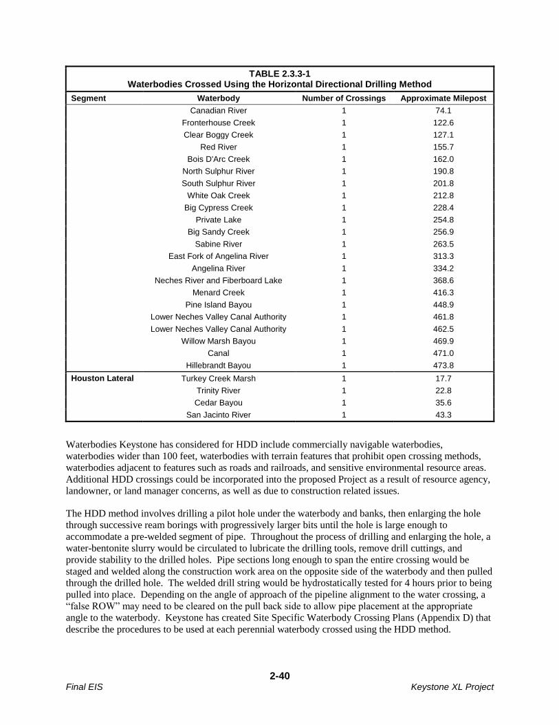
2-40 Final EIS Keystone XL Project
TABLE 2.3.3-1 Waterbodies Crossed Using the Horizontal Directional Drilling Method
Segment Waterbody Number of Crossings Approximate Milepost
Canadian River 1 74.1
Fronterhouse Creek 1 122.6
Clear Boggy Creek 1 127.1
Red River 1 155.7
Bois D'Arc Creek 1 162.0
North Sulphur River 1 190.8
South Sulphur River 1 201.8
White Oak Creek 1 212.8
Big Cypress Creek 1 228.4
Private Lake 1 254.8
Big Sandy Creek 1 256.9
Sabine River 1 263.5
East Fork of Angelina River 1 313.3
Angelina River 1 334.2
Neches River and Fiberboard Lake 1 368.6
Menard Creek 1 416.3
Pine Island Bayou 1 448.9
Lower Neches Valley Canal Authority 1 461.8
Lower Neches Valley Canal Authority 1 462.5
Willow Marsh Bayou 1 469.9
Canal 1 471.0
Hillebrandt Bayou 1 473.8
Houston Lateral Turkey Creek Marsh 1 17.7
Trinity River 1 22.8
Cedar Bayou 1 35.6
San Jacinto River 1 43.3
Waterbodies Keystone has considered for HDD include commercially navigable waterbodies,
waterbodies wider than 100 feet, waterbodies with terrain features that prohibit open crossing methods,
waterbodies adjacent to features such as roads and railroads, and sensitive environmental resource areas.
Additional HDD crossings could be incorporated into the proposed Project as a result of resource agency,
landowner, or land manager concerns, as well as due to construction related issues.
The HDD method involves drilling a pilot hole under the waterbody and banks, then enlarging the hole
through successive ream borings with progressively larger bits until the hole is large enough to
accommodate a pre-welded segment of pipe. Throughout the process of drilling and enlarging the hole, a
water-bentonite slurry would be circulated to lubricate the drilling tools, remove drill cuttings, and
provide stability to the drilled holes. Pipe sections long enough to span the entire crossing would be
staged and welded along the construction work area on the opposite side of the waterbody and then pulled
through the drilled hole. The welded drill string would be hydrostatically tested for 4 hours prior to being
pulled into place. Depending on the angle of approach of the pipeline alignment to the water crossing, a
“false ROW” may need to be cleared on the pull back side to allow pipe placement at the appropriate
angle to the waterbody. Keystone has created Site Specific Waterbody Crossing Plans (Appendix D) that
describe the procedures to be used at each perennial waterbody crossed using the HDD method.
2-41 Final EIS Keystone XL Project
Several commenters on the draft EIS were concerned that the HDD method might damage the pipe or the
protective coating of the pipe. Keystone would use industry standard procedures to ensure pipe and
coating integrity are maintained during HDD installations. This includes application of an abrasion
resistant overcoat to the FBE coating on the pipe joints designated for HDDs. This overcoat prevents
damage to the corrosion resistant FBE coating as the pipe is pulled through the bored hole. During HDD
operations, the hole that is reamed to allow the pipeline to be pulled through is much larger than the pipe
diameter (approximately a 42-inch-diameter hole or larger for the 36-inch-diameter pipe). As noted
above, bentonite drilling mud would be used to reduce friction and provide lubrication and buoyancy for
the pipe during the pull back, assuring minimal contact with the walls of the drill hole. After installation,
Keystone would conduct cathodic protection and in-line inspection surveys to determine if any damage
may have resulted to the pipe coating during the construction process.
Procedures to Avoid or Minimize Impacts of Waterbody Crossings
Equipment refueling and lubricating would take place in upland areas 100 feet or more from the water. If
equipment refueling and lubricating becomes necessary within 100 feet of a perennial waterbody, the
SPCC Plan would be adhered to relative to the handling of fuel and other hazardous materials.
To minimize the potential for sediment runoff during clearing, sediment barriers such as silt fences and
staked straw bales would be installed and maintained on drainages in the ROW and adjacent to
waterbodies and within additional temporary workspace areas. Silt fences and straw bales located across
the working side of the ROW would be removed during the day when vehicle traffic is present and would
be replaced each night. Drivable berms may be installed across the ROW instead of silt fences or straw
bales.
After pipeline installation, stream banks would be restored to preconstruction contours or to a stable
configuration. Stream banks would be seeded for stabilization, and covered with mulch or covered with
erosion control fabric in accordance with the CMR Plan (Appendix B) and applicable state and federal
permit conditions. Stream banks would be temporarily stabilized within 24 hours of completing in-stream
construction. Sediment barriers, such as silt fences, straw bales, or drivable berms, would be maintained
across the ROW at all stream or other waterbody approaches until permanent vegetation becomes
established. Temporary equipment bridges would be removed after construction.
2.3.3.6 Wetland Crossings
Construction across wetlands would be similar to typical conventional upland cross-country construction,
with modifications to reduce the potential for effects to wetland hydrology and soil structure. The
wetland crossing methods used would depend largely on the stability of the soils at the crossing location
at time of construction.
Over most of the ROW, clearing of vegetation in wetlands would be limited to flush-cutting of trees and
shrubs and their subsequent removal from wetland areas. Stump removal, grading, topsoil segregation,
and excavation would be limited to the area immediately over the trench line. During clearing, sediment
barriers, such as silt fences and staked straw bales, would be installed and maintained on slopes adjacent
to saturated wetlands and within additional temporary workspace areas as necessary to reduce sediment
runoff. Tall-growing vegetation would be allowed to regrow in riparian areas in the temporary ROW, but
not in the permanent ROW.
In areas with unsaturated soils that are able to support construction equipment without equipment mats,
construction would occur in a manner similar to conventional upland cross-country construction. Topsoil
removed from the trench line would be segregated and replaced after backfilling the trench with subsoil.
2-42 Final EIS Keystone XL Project
In areas where wetlands overlie rocky soil, the pipe would be padded with rock-free soil or sand before
backfilling with native bedrock and soil.
Where wetland soils are saturated or inundated, the pipeline could be installed using the push-pull
technique. The push-pull installation process would involve stringing and welding the pipeline outside of
the wetland, and excavating and backfilling the trench using a backhoe supported by equipment mats or
timber riprap. Trench breakers would be installed where necessary to prevent the subsurface drainage of
water from wetlands. The pipeline segment would be installed in the wetland by equipping it with floats
and pushing or pulling it across the water-filled trench. After the pipeline is floated into place, the floats
would be removed and the pipeline would sink into place. Most pipes installed in saturated wetlands
would be coated with concrete or installed with set-on weights to provide negative buoyancy. Where
topsoil has been segregated from subsoil, the subsoil would be backfilled first followed by the topsoil.
Restoration of contours would be accomplished during backfilling because little or no grading would
occur in wetlands.
Construction equipment working in saturated wetlands would be limited to that area essential for clearing
the ROW, excavating the trench, welding and installing the pipeline, backfilling the trench, and restoring
the ROW. In areas where there is no reasonable access to the ROW except through wetlands, non-
essential equipment would be allowed to travel through wetlands only if the ground is firm enough or has
been stabilized to avoid rutting. Additional temporary workspace areas would be required on both sides
of wide saturated wetlands to stage construction, weld the pipeline, and store materials. These additional
temporary workspace areas would be located in upland areas a minimum of 10 feet from the wetland
edge. This distance is that a standard backhoe can reach and would avoid the need for additional
equipment to transfer soil farther from the wetland.
Equipment mats, timber riprap, gravel fill, geotextile fabric, and straw mats would be removed from
wetlands after backfilling except in the travel lane to allow continued, controlled access through the
wetland until the completion of construction. Upon the completion of construction, these materials would
be removed. Topsoil would be replaced to the original ground level leaving no crown over the trench
line. Excess excavated material would be removed from the wetland and spread along the upland ROW,
placed in a location as requested by a landowner, or disposed of at an existing authorized landfill.
Where wetlands are located at the base of slopes, permanent slope breakers would be constructed across
the ROW in upland areas adjacent to the wetland boundary. Temporary sediment barriers would be
installed where necessary until revegetation of adjacent upland areas is successful. Once revegetation is
successful, sediment barriers would be removed from the ROW and disposed of at an existing authorized
landfill.
If equipment refueling and lubricating becomes necessary within 100 feet of a wetland, the SPCC Plan
would be adhered to relative to the handling of fuel and other hazardous materials.
2.3.3.7 Ripping
In areas where bedrock is within 84 inches (7 feet) of the surface and is expected to be dense or highly
stratified, ripping could be required. Ripping would involve tearing up the rock with mechanical
excavators. During ripping, Keystone would take extreme care to avoid damage to underground
structures, cables, conduits, pipelines, and underground watercourses.
Keystone anticipates that blasting would not be required. If blasting is necessary, Keystone would
prepare and file a blasting plan with the appropriate agencies.
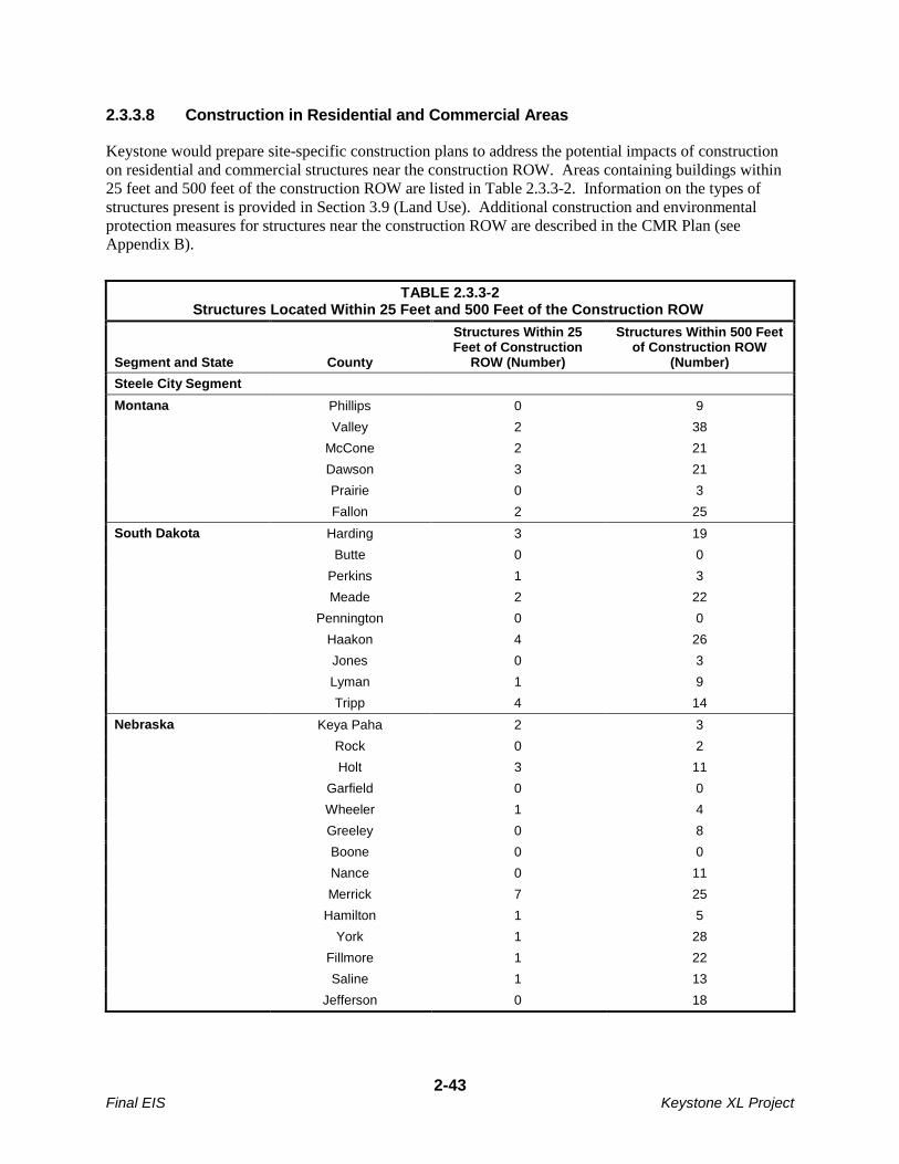
2-43 Final EIS Keystone XL Project
2.3.3.8 Construction in Residential and Commercial Areas
Keystone would prepare site-specific construction plans to address the potential impacts of construction
on residential and commercial structures near the construction ROW. Areas containing buildings within
25 feet and 500 feet of the construction ROW are listed in Table 2.3.3-2. Information on the types of
structures present is provided in Section 3.9 (Land Use). Additional construction and environmental
protection measures for structures near the construction ROW are described in the CMR Plan (see
Appendix B).
TABLE 2.3.3-2 Structures Located Within 25 Feet and 500 Feet of the Construction ROW
Segment and State County
Structures Within 25 Feet of Construction
ROW (Number)
Structures Within 500 Feet of Construction ROW
(Number)
Steele City Segment
Montana Phillips 0 9
Valley 2 38
McCone 2 21
Dawson 3 21
Prairie 0 3
Fallon 2 25
South Dakota Harding 3 19
Butte 0 0
Perkins 1 3
Meade 2 22
Pennington 0 0
Haakon 4 26
Jones 0 3
Lyman 1 9
Tripp 4 14
Nebraska Keya Paha 2 3
Rock 0 2
Holt 3 11
Garfield 0 0
Wheeler 1 4
Greeley 0 8
Boone 0 0
Nance 0 11
Merrick 7 25
Hamilton 1 5
York 1 28
Fillmore 1 22
Saline 1 13
Jefferson 0 18
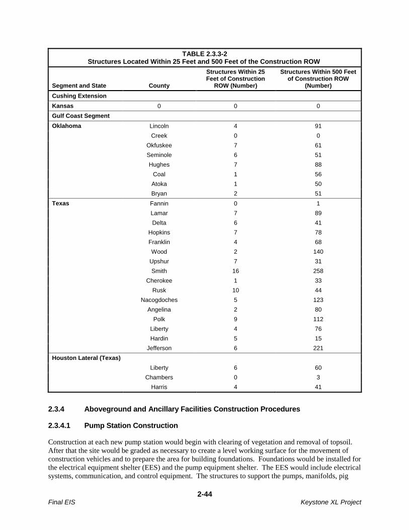
2-44 Final EIS Keystone XL Project
TABLE 2.3.3-2 Structures Located Within 25 Feet and 500 Feet of the Construction ROW
Segment and State County
Structures Within 25 Feet of Construction
ROW (Number)
Structures Within 500 Feet of Construction ROW
(Number)
Cushing Extension
Kansas 0 0 0
Gulf Coast Segment
Oklahoma Lincoln 4 91
Creek 0 0
Okfuskee 7 61
Seminole 6 51
Hughes 7 88
Coal 1 56
Atoka 1 50
Bryan 2 51
Texas Fannin 0 1
Lamar 7 89
Delta 6 41
Hopkins 7 78
Franklin 4 68
Wood 2 140
Upshur 7 31
Smith 16 258
Cherokee 1 33
Rusk 10 44
Nacogdoches 5 123
Angelina 2 80
Polk 9 112
Liberty 4 76
Hardin 5 15
Jefferson 6 221
Houston Lateral (Texas)
Liberty 6 60
Chambers 0 3
Harris 4 41
2.3.4 Aboveground and Ancillary Facilities Construction Procedures
2.3.4.1 Pump Station Construction
Construction at each new pump station would begin with clearing of vegetation and removal of topsoil.
After that the site would be graded as necessary to create a level working surface for the movement of
construction vehicles and to prepare the area for building foundations. Foundations would be installed for
the electrical equipment shelter (EES) and the pump equipment shelter. The EES would include electrical
systems, communication, and control equipment. The structures to support the pumps, manifolds, pig
2-45 Final EIS Keystone XL Project
receiving and pig launching equipment, densitometers (where present), and associated facilities would
then be erected. This would include installation of a block valve into the mainline as well as two MLV
block valves: one would be installed on the suction piping of the pumps and one would be installed on the
discharge piping of the pumps as required by 49 CFR 195.260.
The piping, both aboveground and below ground, would be installed and pressure tested using the
methods employed for the main pipeline. After successful testing, the piping would be tied into the main
pipeline. Piping installed below grade would be coated for corrosion protection as required by 49 CFR
195 Subpart H (Corrosion Control) and the applicable Project-specific PHMSA special conditions. In
addition, all below-grade facilities would be protected by a cathodic protection system as required by
Subpart H and the applicable Project-specific PHMSA special conditions. Pumps, controls, and safety
devices would be checked and tested to ensure proper system operation and activation of safety
mechanisms before being put into service. After hydrostatic testing of the below-grade equipment, the
site would be graded and surfaced with gravel and a security fence would be installed around the entire
perimeter of each site.
Construction activities and the storage of construction materials would be confined to each pump station
site. Figures 2.2.3-1 and 2.2.3-2 are plot plans for typical pump stations.
2.3.4.2 Tank Farm Construction
The tank farm would be installed on a 74-acre site that would also include pump station 32. Wildhorse
Creek extends through the site, but there would not be any construction activities in the creeks or on its
banks. Portions of the site to be developed would be cleared and graded to create a level work surface for
the tanks. The 350,000-barrel tanks would be welded steel tanks with external floating roofs that would
be installed inside an impervious bermed area that would act as secondary containment. The piping in the
tank farm area would be both above and below ground. The tanks and associated piping would be
isolated electrically from the pipeline and protected by a separate cathodic protection system. The tank
farm would use the electrical supply and control system of the adjacent pump station (see Figure 2.2.6-1).
The tank farm would be final graded and a permanent security fence would be installed around the entire
perimeter of the 74-acre site.
After successful hydrostatic testing of the tanks and associated piping and manifolds, the control system
would be put into service and the tanks would be connected to the pipeline via the manifold. Each tank
would have a separate water screen and fire suppression system supplied by an on-site fire water supply
pond. A separate larger pond would be installed to manage storm water and mitigate any potential
contamination from the site.
2.3.4.3 Mainline Valves and Delivery Sites
MLV construction would occur during mainline pipeline construction. All MLVs would be within the
permanent ROW. To facilitate year-round access, the MLVs would be located as near as practicable to
existing public roads. The construction sequence would consist of clearing and grading followed by
trenching, valve installation, fencing, cleanup, and site restoration. If necessary, new access roads would
be constructed into the fenced MLV sites. Two 10,417-barrel surge relief tanks would be installed at the
end of the Gulf Coast Segment in Nederland on at a previously disturbed site with an industrial property.
The area would be graded as necessary for installation of the tank foundations, and the tanks would be
installed inside a bermed, impervious area that would act as secondary containment.
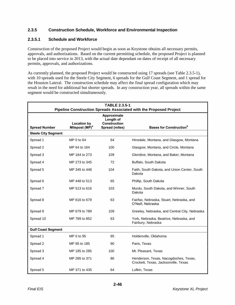
2-46 Final EIS Keystone XL Project
2.3.5 Construction Schedule, Workforce and Environmental Inspection
2.3.5.1 Schedule and Workforce
Construction of the proposed Project would begin as soon as Keystone obtains all necessary permits,
approvals, and authorizations. Based on the current permitting schedule, the proposed Project is planned
to be placed into service in 2013, with the actual date dependant on dates of receipt of all necessary
permits, approvals, and authorizations.
As currently planned, the proposed Project would be constructed using 17 spreads (see Table 2.3.5-1),
with 10 spreads used for the Steele City Segment, 6 spreads for the Gulf Coast Segment, and 1 spread for
the Houston Lateral. The construction schedule may affect the final spread configuration which may
result in the need for additional but shorter spreads. In any construction year, all spreads within the same
segment would be constructed simultaneously.
TABLE 2.3.5-1 Pipeline Construction Spreads Associated with the Proposed Project
Spread Number Location by
Milepost (MP)a
Approximate Length of
Construction Spread (miles) Bases for Construction
b
Steele City Segment
Spread 1 MP 0 to 64 64 Hinsdale, Montana, and Glasgow, Montana
Spread 2 MP 64 to 164 100 Glasgow, Montana, and Circle, Montana
Spread 3 MP 164 to 273 109 Glendive, Montana, and Baker, Montana
Spread 4 MP 273 to 345 72 Buffalo, South Dakota
Spread 5 MP 345 to 448 104 Faith, South Dakota, and Union Center, South Dakota
Spread 6 MP 448 to 513 65 Phillip, South Dakota
Spread 7 MP 513 to 616 103 Murdo, South Dakota, and Winner, South Dakota
Spread 8 MP 616 to 679 63 Fairfax, Nebraska, Stuart, Nebraska, and O’Neill, Nebraska
Spread 9 MP 679 to 789 109 Greeley, Nebraska, and Central City, Nebraska
Spread 10 MP 789 to 852 63 York, Nebraska, Beatrice, Nebraska, and Fairbury, Nebraska
Gulf Coast Segment
Spread 1 MP 0 to 95 95 Holdenville, Oklahoma
Spread 2 MP 95 to 185 90 Paris, Texas
Spread 3 MP 185 to 285 100 Mt. Pleasant, Texas
Spread 4 MP 285 to 371 86 Henderson, Texas, Nacogdoches, Texas, Crockett, Texas, Jacksonville, Texas
Spread 5 MP 371 to 435 64 Lufkin, Texas
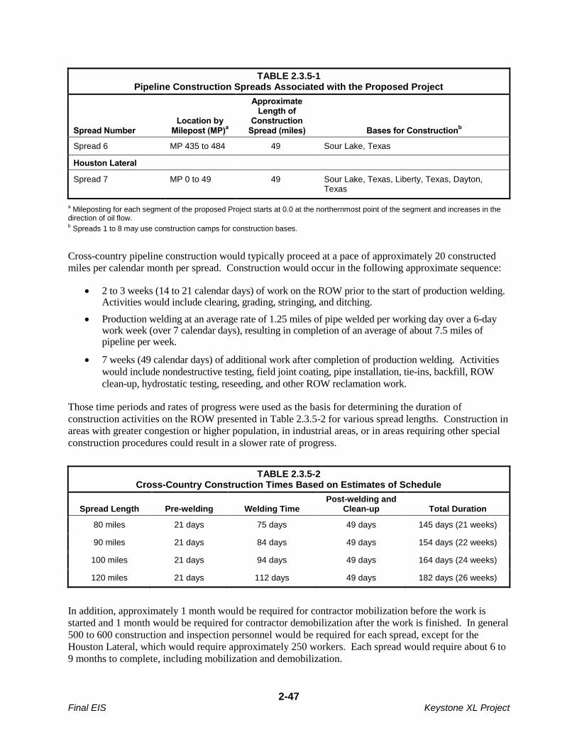
2-47 Final EIS Keystone XL Project
TABLE 2.3.5-1 Pipeline Construction Spreads Associated with the Proposed Project
Spread Number Location by
Milepost (MP)a
Approximate Length of
Construction Spread (miles) Bases for Construction
b
Spread 6 MP 435 to 484 49 Sour Lake, Texas
Houston Lateral
Spread 7 MP 0 to 49 49 Sour Lake, Texas, Liberty, Texas, Dayton, Texas
a Mileposting for each segment of the proposed Project starts at 0.0 at the northernmost point of the segment and increases in the
direction of oil flow. b Spreads 1 to 8 may use construction camps for construction bases.
Cross-country pipeline construction would typically proceed at a pace of approximately 20 constructed
miles per calendar month per spread. Construction would occur in the following approximate sequence:
2 to 3 weeks (14 to 21 calendar days) of work on the ROW prior to the start of production welding. Activities would include clearing, grading, stringing, and ditching.
Production welding at an average rate of 1.25 miles of pipe welded per working day over a 6-day work week (over 7 calendar days), resulting in completion of an average of about 7.5 miles of pipeline per week.
7 weeks (49 calendar days) of additional work after completion of production welding. Activities
would include nondestructive testing, field joint coating, pipe installation, tie-ins, backfill, ROW
clean-up, hydrostatic testing, reseeding, and other ROW reclamation work.
Those time periods and rates of progress were used as the basis for determining the duration of
construction activities on the ROW presented in Table 2.3.5-2 for various spread lengths. Construction in
areas with greater congestion or higher population, in industrial areas, or in areas requiring other special
construction procedures could result in a slower rate of progress.
TABLE 2.3.5-2 Cross-Country Construction Times Based on Estimates of Schedule
Spread Length Pre-welding Welding Time Post-welding and
Clean-up Total Duration
80 miles 21 days 75 days 49 days 145 days (21 weeks)
90 miles 21 days 84 days 49 days 154 days (22 weeks)
100 miles 21 days 94 days 49 days 164 days (24 weeks)
120 miles 21 days 112 days 49 days 182 days (26 weeks)
In addition, approximately 1 month would be required for contractor mobilization before the work is
started and 1 month would be required for contractor demobilization after the work is finished. In general
500 to 600 construction and inspection personnel would be required for each spread, except for the
Houston Lateral, which would require approximately 250 workers. Each spread would require about 6 to
9 months to complete, including mobilization and demobilization.
2-48 Final EIS Keystone XL Project
Tank farm construction would involve approximately 30 to 40 construction personnel over a period of 15
to 18 months concurrent with mainline construction. Construction of new pump stations would require
20 to 30 additional workers at each site. Construction of all pump stations would be completed in 18 to
24 months.
A peak workforce of approximately 5,000 to 6,000 personnel would be required to construct the entire
Project and would be spread along the nearly 1,384-mile-long route. All workers would be trained and
certified for their specific field of work (e.g., welders would be qualified as required by 49 CFR 195.222
and the Project-specific PHMSA special condition 18). Construction personnel would consist of
Keystone employees, contractor employees, construction inspection staff and environmental inspection
staff. Keystone would attempt to hire construction staff from the local population through its construction
contractors and subcontractors. Assuming that qualified personnel are available, approximately 10 to
15 percent (50 to 100 people per spread) could be hired from the local work force for each spread,
although this may not be possible in rural areas.
2.3.5.2 Environmental Inspection
Keystone would use Environmental Inspectors on each construction spread. The Environmental
Inspectors would review the Project activities daily for compliance with state, federal, and local
regulatory requirements and would have the authority to stop specific tasks as approved by the Chief
Inspector. The inspectors would also be able to order corrective action in the event that construction
activities violate the provisions of the CMR Plan, landowner requirements, or any applicable permit
requirements.
2.4 OPERATIONS AND MAINTENANCE
The proposed Project would be operated, maintained, monitored, and inspected in accordance with 49
CFR 194 and 195 and other applicable federal and state regulations. In addition to the requirements of 49
CFR 195, Keystone has agreed to incorporate 57 PHMSA Project-specific special conditions that address
proposed Project operation, inspection, and monitoring (see Appendix U). The operational requirements
of 49 CFR 195 and the PHMSA Project-specific Special Conditions related to operation of the proposed
Project (Appendix U) would be included in the proposed Project operations, maintenance, and
emergencies manual that would be required by 49 CFR 195.402, and they would also be incorporated into
Keystone’s existing Operations Control Center (OCC) in Calgary, Canada.
The remainder of this section addresses normal operation and routine maintenance (Section 2.4.1) and
abnormal operations (Section 2.4.2).
2.4.1 Normal Operations and Routine Maintenance
Keystone would prepare the manuals and written procedures for conducting normal operations,
maintenance, inspection, and monitoring activities as required by the PHMSA regulations, particularly as
required by 49 CFR 195.402 and in the applicable PHMSA Project-specific special conditions (see
Appendix U). This would include development and implementation of an annual Pipeline Maintenance
Program (PMP) to ensure the integrity of the pipeline. The PMP would include valve maintenance,
periodic inline inspections, and cathodic protection readings to ensure facilities are reliable and in service.
Data collected in each year of the program would be fed back into the decision-making process for the
development of the following year’s program.
The Project OCC would be manned by experienced and highly trained personnel 24 hours per day, every
day of the year in Calgary. In addition, a fully redundant backup OCC would be constructed, operated,
2-49 Final EIS Keystone XL Project
and maintained, also in Canada. Primary and backup communications systems would provide real-time
information from the pump stations to field personnel. The control center would have highly
sophisticated pipeline monitoring systems including a leak detection system capable of identifying
abnormal conditions and initiating visual and audible alarms. Automatic shut down systems would be
initiated if a valve starts to shut and all pumps upstream would turn off automatically. All other pipeline
situations would require human response.
The proposed Project would include a supervisory control and data acquisition (SCADA) system to
constantly monitor the pipeline system. The SCADA system would be installed and operated in
accordance with the requirements of 49 CFR 195 and PHMSA Project-specific special conditions 24
through 31 (see Appendix U). SCADA facilities would be located in the OCC and along the pipeline
system, and all pump stations and delivery facilities would have communication software that sends data
back to the OCC. The pipeline SCADA system would allow the OCC to remotely read intermediate
MLV positions, tank levels, and delivery flow and total volume. The OCC personnel would also be able
to start and stop pump stations and open and close MLVs. SCADA systems are further discussed in
Sections 2.4.2.1 and 3.13.4.5.
The pipeline ROW would be inspected via aerial and ground surveillance to provide prompt identification
of possible encroachments or nearby construction activities, ROW erosion, exposed pipe, or any other
conditions that could result in damage to the pipeline. The aerial surveillance of the pipeline ROW would
be carried out at least 26 times per year at intervals not to exceed 3 weeks as required by 49 CFR 195.412.
Landowners would be encouraged to report any pipeline integrity concerns to Keystone or to PHMSA.
Intermediate MLVs and MLVs at pump stations would also be inspected. As required by 49 CFR
195.420(b), they would be inspected at intervals not to exceed 7.5 months but at least twice each calendar
year.
In comments on the supplemental draft EIS, EPA expressed concern that relying solely on pressure drops
and aerial surveys to detect leaks may result in smaller leaks going undetected for some time, resulting in
potentially large spill volumes. In light of those concerns, EPA requested consideration of additional
measures to reduce the risks of undetected leaks. A PHMSA report (2007) addressed the state of leak
detection technology and its applicability to pipeline leak detection. External leak detection technology
addressed included liquid sensing cables, fiber optic cables, vapor sensing, and acoustic emissions. In
that report PHMSA concludes that while external leak detection systems have proven results for
underground storage tank systems there are limitations to their applicability to pipeline systems and they
are better suited to shorter pipeline segments. Their performance even in limited application is affected by
soil conditions, depth to water table, sensor spacing, and leak rate. While it is acknowledged that some
external detection methods are more sensitive to small leaks than the SCADA computational approach,
the stability and robustness of the systems are highly variable and the costs are extremely high.
Therefore, long-term reliability is not assured and the efficacy of these systems for a 1,384-mile long
pipeline is questionable. It may be possible, however, to incorporate external leak detection methods
along discrete segments of pipeline where particularly sensitive resources may exist. For example, in the
development of the original Keystone pipeline, specific analysis was commissioned at the request of the
North Dakota Public Utilities Commission to examine the possibility of using external leak detection in
the area of the Fordville aquifer. That analysis was performed by Accufacts, Inc., a widely recognized
expert on pipeline safety that has authored a report for the Pipeline Safety Trust on leak detection
technology. The Accufacts, Inc. report (2007) on the Fordville aquifer noted:
“Such real-time external systems should be considered as complementing CPM [computational
pipeline monitoring] leak detection in those few ultra-sensitive areas where the environment can
quickly spread low rate releases. These systems may be justified in a few areas that can have
2-50 Final EIS Keystone XL Project
high consequences because of the number of sensitive receptors (i.e., people) or the potential to
critically impact the environment.”
The author of the report defined “ultra-sensitive” areas as those areas where low rate or seepage pipeline
release could “reach a sensitive area, have serious consequences, and could not be actively remediated.”
(Accufacts, Inc. 2007).
DOS in consultation with PHMSA and EPA determined that Keystone should commission an engineering
analysis by an independent consultant that would review the proposed Project risk assessment and
proposed valve placement. The engineering analysis would, at a minimum, assess the advisability of
additional valves and/or the deployment of external leak detection systems in areas of particularly
sensitive environmental resources. The scope of the analysis and the selection of the independent
consultant would be approved by DOS in consultation with PHMSA and EPA. After completion and
review of the engineering analysis, DOS with concurrence from PHMSA and EPA would determine the
need for any additional mitigation measures.
Relative to additional ground patrols, Keystone responded to a data request from DOS concerning the
feasibility of more ground-level inspections. Keystone responded that based on land owner concerns,
additional ground-level inspections are not feasible due to potential disruption of normal land use
activities (e.g., farming, animal grazing). PHMSA technical staff indicated that such concerns about
landowner acceptance of more frequent ground-level inspections were consistent with their experience
with managing pipelines in the region. Although widespread use of ground-level inspections may not be
warranted, in the start-up year it is not uncommon for pipelines to experience a higher frequency of spills
from valves, fittings, and seals. Such incidences are often related to improper installation, or defects in
materials. In light of this fact, DOS in consultation with PHMSA and EPA determined that if the
proposed Project were permitted, it would be advisable for the applicant to conduct inspections of all
intermediate valves, and unmanned pump stations during the first year of operation to facilitate
identification of small leaks or potential failures in fittings and seals. In the normal course of
maintenance beyond the first year of operation, Keystone would have crews at various places along the
proposed Project corridor (e.g., maintenance inspections of cathodic protection system rectifiers, MLVs,
and pump stations). These crews would be trained and experienced in the identification of crude oil
releases. It should be noted that the 14 leaks from fittings and seals that have occurred to date on the
existing Keystone Oil Pipeline were identified from the SCADA leak detection system and landowner
reports.
PHMSA regulations at 49 CFR 195.450 and Special Condition 14 require that pipeline operators identify
areas along the proposed pipeline corridor that would be considered High Consequence Areas (HCAs).
While some of these areas need to be defined through sophisticated risk modeling, in general they are
specific locales where an accidental release from a hazardous liquid pipeline could produce significant
adverse consequences as described in 49 CFR 195.450. HCAs include navigable waterways, high
population areas, and unusually sensitive areas. Keystone would need to identify the HCAs along the
proposed route. Population changes along the route would be monitored throughout pipeline operation
and any additional HCAs identified as necessary. Keystone would conduct a pipeline integrity
management program in HCAs as required by 49 CFR 195.452 (Pipeline Integrity Management in High
Consequence Areas).
All maintenance work would be performed in accordance with PHMSA requirements, the applicable
PHMSA Special Conditions, and the stipulations in environmental permits issued for the proposed
Project. Woody vegetation along the permanent easement would be cleared periodically in order to
maintain accessibility for pipeline integrity surveys. Mechanical mowing or cutting would be carried out
from time to time as needed along the permanent easement for normal vegetation maintenance.
2-51 Final EIS Keystone XL Project
Cultivated crops would be allowed to grow in the permanent easement, but trees would be removed from
the permanent ROW in all areas. In areas constructed using the HDD method, trees would be cleared as
required on a site specific basis.
Permanent erosion control devices would be monitored to identify any areas requiring repair. The
remainder of the ROW would be monitored to identify areas where additional erosion control devices
would be necessary to prevent future degradation. The ROW would be monitored to identify any areas
where soil productivity has been degraded as a result of pipeline construction. In these areas, reclamation
measures would be implemented to rectify the problems.
Operation and maintenance of the pipeline system would typically be accomplished by Keystone
personnel. The permanent operational pipeline workforce would comprise about 20 U.S. employees
strategically located along the length of the pipeline in the U.S.
2.4.2 Abnormal Operations
Keystone would implement Abnormal Operating Procedures in accordance with 49 CFR Section
195.402(d). Those procedures would be developed and documented in a manual as required by 49 CFR
195.402. The manual would include procedures to provide safety when operating design limits have been
exceeded. That would include investigating and correcting the cause of unintended closure of valves or
shutdowns, increases or decreases in pressure or flow rate outside normal operating limits, loss of
communications, operation of any safety device, and any other malfunction of a component, deviation
from normal operation, or personnel error which could cause a hazard to persons or property. Procedures
would also include checking variations from normal operation after abnormal operation has ended at
sufficient critical locations in the system to accomplish the following:
Assure continued integrity and safe operation;
Identify variations from normal operation of pressure and flow equipment and controls;
Notify responsible operator personnel when notice of an abnormal operation is received;
Review periodically the response of operator personnel to determine the effectiveness of the procedures controlling abnormal operation; and
Take corrective action where deficiencies are found.
The operations manager on duty would be responsible for executing abnormal operating procedures in the
event of any unusual situation.
2.4.2.1 Pipeline Integrity, SCADA, and Leak Detection
The following overlapping and redundant integrity systems and measures would be incorporated into the
proposed Project:
Quality Assurance (QA) program for pipe manufacture and pipe coating;
FBE coating;
Cathodic protection;
Non-destructive testing of 100 percent of the girth welds;
Hydrostatic testing;
Periodic internal cleaning and high-resolution in-line inspection;
2-52 Final EIS Keystone XL Project
Depth of cover exceeding federal standards;
Periodic aerial surveillance;
Public awareness program;
SCADA system; and
An OCC with complete redundant backup, providing monitoring of the pipeline every 5 seconds,
24 hours per day, every day of the year.
SCADA facilities would be used to remotely monitor and control the pipeline system. This would
include a redundant fully functional backup system available for service at all times. Automatic features
would be installed as integral components within the SCADA system to ensure operation within
prescribed pressure limits. Additional automatic features would be installed at the local pump station
level and would provide pipeline pressure protection in the event communications with the SCADA host
are interrupted.
Software associated with the SCADA monitoring system and volumetric balancing would be used to
assist in leak detection during pipeline operations. If pressure indications change, the pipeline controller
would immediately evaluate the situation. If a leak is suspected, the ERP would be initiated, as described
in Section 2.4.2.2. If there is a pipeline segment shutdown due to a suspected leak, operation of the
affected segment would not be resumed until the cause of the alarm (e.g., false alarm by instrumentation
or a leak) is identified and repaired. In the case of a reportable leak, OHMSA approval would be required
to resume operation of the affected segment.
A number of complementary leak detection methods and systems would be available within the OCC and
would be linked to the SCADA system. Remote monitoring would consist primarily of monitoring
pressure and flow data received from pump stations and valve sites that would be fed back to the OCC by
the SCADA system. Software based volume balance systems would monitor receipt and delivery
volumes and would detect leaks down to approximately 5 percent of pipeline flow rate. Computational
Pipeline Monitoring or model-based leak detection systems would separate the pipeline system into
smaller segments and would monitor each segment on a mass balance basis. These systems would detect
leaks down to a level of approximately 1.5 to 2 percent of the pipeline flow rate. Computer-based, non-
real time, accumulated gain/loss volume trending would assist in identifying low rate or seepage releases
below the 1.5 to 2 percent by volume detection thresholds. If any of the software-based leak detection
methods indicates that a predetermined loss threshold has been exceeded, an alarm would be sent through
SCADA and the Controller would take corrective action. The SCADA system would continuously poll
all data on the pipeline at an interval of approximately 5 seconds
If an accidental release were to occur, the operator would shut down operating pumping units and close
the isolation valves. Once shutdown activities are initiated, it would take approximately 9 minutes to
complete the emergency shut-down procedure (shut down operating pumping units) and an additional 3
minutes to close the isolation valves.
In addition to the SCADA and complimentary leak detection systems, direct observation methods,
including aerial patrols, ground patrols and public and landowner awareness programs, would be
implemented to encourage and facilitate the reporting of suspected leaks and events that could suggest a
threat to the integrity of the pipeline.
Several commenters suggested that external mechanical leak detection systems should be considered. In
response, DOS requested information from Keystone regarding the feasibility of installing mechanical
external leak detection systems along the proposed Project corridor. Keystone considers that the presently
2-53 Final EIS Keystone XL Project
available technology for external leak detection is not practicable for use along a 1,384 mile pipeline.
Additionally, a PHMSA report (2007) addressed the state of leak detection technology and its
applicability to pipeline leak detection. External leak detection technology addressed included liquid
sensing cables, fiber optic cables, vapor sensing, and acoustic emissions. In that report PHMSA
concludes that while external leak detection systems have proven results for underground storage tank
systems there are limitations to their applicability to pipeline systems and they are better suited to shorter
pipeline segments. Their performance even in limited application is affected by soil conditions, depth to
water table, sensor spacing, and leak rate. While it is acknowledged that some external detection methods
are more sensitive to small leaks than the SCADA computational approach, the costs are extremely high
and the stability and robustness of the systems are highly variable. Therefore, long-term reliability is not
assured and the efficacy of these systems for a 1,384-mile long pipeline is questionable.
2.4.2.2 Emergency Response Procedures
There were many comments on the draft EIS concerning the ERP, including suggestions that a
supplemental draft EIS be issued to include a more complete ERP and allow for public review of that
plan. Those issues are addressed below along with additional information on the proposed Project ERP.
Section 3.13.1.1 provides additional information on the regulations associated with an ERP.
PHMSA requires that pipeline operators prepare and abide by more than one written emergency plan for
responding to emergencies on their systems.
First, 49 CFR 194, which resulted from the CWA as amended by the Oil Pollution Act of 1990 (OPA 90)
and as implemented by Executive Order 12777, requires that pipeline operators have response plans that
ensure resources are available to remove, mitigate, or prevent a discharge from an oil pipeline that could
cause substantial or significant harm to the environment, including a worst case discharge. As stated in
49 CFR 194.7(a), a pipeline operator “may not handle, store, or transport oil unless the operator has
submitted a response plan meeting requirements of this part,” and as stated in 49 CFR 194.7(b), operators
must also operate onshore pipeline facilities in accordance with the approved response plan. In addition,
49 CFR 194.107 requires that the response plan include “procedures and a list of resources for
responding, to the maximum extent practicable, to a worst case discharge, and to a substantial threat of
such a discharge.” Keystone would submit a Pipeline Spill Response Plan (PSRP) to PHMSA prior to the
initiation of proposed Project operations in accordance with the requirements of 49 CFR 194. The PSRP
would describe how spills would be responded to in the event of a release from the proposed Project
resulting from any cause (e.g., corrosion, third-party damage, natural hazards, materials defects, hydraulic
surge). The plan would address the maximum spill scenario and the procedures that would be in place to
deal with the maximum spill. The PSRP requires PHMSA review and approval; however, there is a 2-
year grace period under which operations can proceed, thus allowing PHMSA time to review the
document in light of as-built Project conditions and to require incorporation of any needed changes to
ensure system safety prior to PHMSA approval.
As required by 49 CFR 195.40, Keystone would also prepare and follow a manual of written procedures
for conducting normal operations and maintenance activities and handling abnormal operations and
emergencies. This manual would be reviewed by PHMSA at intervals not exceeding 15 months, but at
least once each calendar year, and appropriate changes would be made as necessary to ensure that the
manual is effective. This manual would be prepared before initial operations of the proposed Project and
appropriate sections would be kept at locations where operations and maintenance activities are
conducted. The emergency section of this operations and maintenance plan would be prepared by
Keystone in a separate document that Keystone refers to as the Emergency Response Plan (ERP).
2-54 Final EIS Keystone XL Project
While EPA has authority under the CWA and OPA 90 with respect to regulation of onshore non-
transportation related facilities and EPA requires the development and submittal of a Facility Response
Plan (FRP) for any such facility, it appears that none of the facilities or activities associated with the
proposed Project would be non-transportation-related equipment or activities subject to the EPA
regulatory authority, as previously noted in Section 2.3.
Keystone would therefore be required to develop a PSRP for review and approval by PHMSA and an
ERP for review by PHMSA for the proposed Project. PHMSA may request EPA and U.S. Coast Guard
consultation on the response elements of the PSRP. Keystone would share on its own volition portions of
the PSRP with community emergency responders along the proposed pipeline corridor to ensure an
appropriate level of collaborative emergency response planning. However, based on a PHMSA advisory
bulletin issued on November 3, 2010, Keystone would be required to share the ERP with local emergency
responders in relevant jurisdictions along the proposed Project corridor.
While the draft PSRP and the draft ERP for the proposed Project are not yet available, Keystone prepared
similar plans for the existing Keystone Oil Pipeline Project. These plans for the proposed Project would
have the same general approach as those plans but would have many specific differences, such as the
names and contact information for responders along the proposed Project route. The publically available
portion of the Keystone Oil Pipeline System ERP is included as Appendix C to the EIS (some of the ERP
and the PSRP are considered confidential by PHMSA and the U.S. Department of Homeland Security).
As described in Section 3.13.1.1, the existing Keystone Oil Pipeline Project documents would be used as
templates for the plans for the proposed Project. Project-specific information would be inserted into the
plans as it becomes available. In addition, response equipment would be procured and strategically
positioned along the route, staff would be trained in spill response and the Incident Command System,
and emergency services and public officials would be educated on all aspects of the proposed Project and
what their roles would be if an accidental release were to occur. If a release were to occur, Keystone and
its contractors would be responsible for recovery and cleanup. PHMSA would require a certification
from Keystone that necessary emergency response equipment is available in the event of an unplanned
spill prior to providing Keystone with an authorization to begin operating the proposed Project.
The specific locations of Keystone’s emergency responders and equipment would be determined upon
conclusion of the pipeline detailed design and described in the PSRP and ERP. Company emergency
responders would be placed consistent with industry practice and with applicable regulations, including
49 CFR Parts 194 and 195. The response time to transfer additional resources to a potential leak site
would follow an escalating tier system, with initial emergency responders capable of reaching all
locations within 6 hours in the event of a spill. Typically, emergency responders would be based in closer
proximity to the following areas:
Commercially navigable waterways and other water crossings;
Populated and urbanized areas; and
Unusually sensitive areas, including drinking water locations, ecological, historical, and
archaeological resources.
Types of emergency response equipment situated along the pipeline route would include pick-up trucks,
one-ton trucks and vans; vacuum trucks; work and safety boats; containment boom; skimmers; pumps,
hoses, fittings and valves; generators and extension cords; air compressors; floodlights; communications
equipment including cell phones, two way radios and satellite phones; containment tanks and rubber
bladders; expendable supplies including absorbent booms and pads; assorted hand and power tools
including shovels, manure forks, sledge hammers, rakes, hand saws, wire cutters, cable cutters, bolt
cutters, pliers and chain saws; ropes, chains, screw anchors, clevis pins and other boom connection
2-55 Final EIS Keystone XL Project
devices; personnel protective equipment (PPE) including rubber gloves, chest and hip waders and
airborne contaminant detection equipment; and wind socks, signage, air horns, flashlights, megaphones
and fluorescent safety vests. Emergency response equipment would be maintained and tested in
accordance with manufacturers recommendations.
Additional equipment including helicopters, fixed wing aircraft, all-terrain vehicles, snowmobiles,
backhoes, dump trucks, watercraft, bull dozers, and front-end loaders could also be accessed depending
upon site-specific circumstances. Other types, numbers and locations of equipment would be determined
upon conclusion of the pipeline detailed design and the completion of the PSRP and the ERP for the
proposed Project.
Several federal regulations define the notification requirements and response actions in the case of an
accidental release, including the National Oil and Hazardous Substances Pollution Contingency Plan (40
CFR Part 300), the CWA, and OPA 90.
If an accidental release occurs, Keystone would implement several procedures to mitigate damage,
including a line shut down. Other procedures would include immediate dispatch of a first responder to
verify the release and secure the site. Simultaneously, an Incident Command System would be
implemented and internal and external notifications would take place. The National Response Center
(NRC) would be notified if the release meets one of the prescribed criteria. Keystone and the NRC would
also notify other regional and local emergency response agencies as quickly as possible. All of this
information would be included in the ERP for the proposed Project.
Many commenters expressed concern that an accidental release of heavy crude oil from the proposed
Project would require unique methods to clean up the oil. As described in Section 3.13.5.3, heavy WCSB
crude oil is similar to heavy crude oil currently being processed in refineries in the Houston area and
elsewhere in the U.S. Therefore, the methods used to cleanup crude oil accidentally released from the
proposed Project would be similar to methods used elsewhere in the U.S. to address a heavy crude oil
release.
Some commenters also suggested that the EIS should provide alternatives to the ERP and evaluate those
alternatives as a part of the NEPA environmental review process. Keystone’s ERP would be prepared to
meet the PHMSA requirements in 49 CFR 195.40 and would reflect actual field conditions. Additionally,
Keystone’s PSRP would be prepared to meet the requirements of 49 CFR 194. Due to the range of
possible accidental release scenarios (including timing, size, location, season, weather conditions, and
many other variables), it is not possible to assess the impact of each and every response and cleanup
scenario. As a result, NEPA environmental reviews do not assess the relative effectiveness of specific
procedures and PSRP and ERP alternatives.
In the event of a suspected release or if a release is reported to the OCC, after verification there would be
an emergency pipeline shutdown. This would involve stopping all operating pumping units at all pump
stations. The on-call response designate would respond to and verify an incident. Once the OCC notifies
the individual and an assessment of the probability and risk is established, field personnel could elect to
dispatch other resources as soon as practical. Response efforts would first be directed to preventing or
limiting any further contamination of the waterway, once any concerns with respect to health and safety
of the responders have been addressed.
Many commenters expressed concern about abnormal pipeline operations that could result in an
explosion. A review of PHMSA data related to pipeline accidents indicates that most “petroleum or
hydrocarbon pipeline explosions” occur in pipelines that are transporting highly flammable, highly
volatile hydrocarbons such as natural gas, liquid propane gas (LPG), propane, gasoline, naphtha, or
2-56 Final EIS Keystone XL Project
similar products. Typically, any of those materials accidentally released from the pipeline form a
flammable vapor cloud that can explode when it reaches a certain concentration level in air, particularly
in a confined space. In rare cases diesel, gas condensate, kerosene, or similarly-refined liquid
hydrocarbon ignite and burn explosively if the vapors are exposed to a fire or similar high temperature
heat source, usually a fire caused by some other accident.
As noted in Section 3.13, PHMSA data for onshore oil and hazardous material pipelines indicate that only
6 of 2,706 (0.2 percent) of incidents that occurred from 1990 through 2009 were attributed to
“fire/explosion as a primary cause.” A search of the internet for reports of crude oil pipeline explosions
suggests that (1) there are very few if any explosions in crude oil pipeline operation that were the result of
a failure of the pipeline as a primary cause, and (2) the very few that have occurred are attributable to
explosions in ancillary facilities or errors in operations unassociated with crude oil transportation. For
example, the recent explosion and fire in the crude oil pipeline/storage tank area in Dalian, China
occurred as a result of an improper desulfurization operation; the primary cause was not the transport of
crude oil in the pipeline.
The proposed Project would use pump stations that are powered by electricity; as a result, there would not
be natural gas or other petroleum products at the facility that could ignite explosively. An accidental
crude oil spill from the pipeline or at a pump station would likely result in some hydrocarbon vapors, but
they would not be in confined spaces and therefore would be unlikely to explode.
A fire associated with a release from a crude oil pipeline is relatively rare. In the event of a fire, local
emergency responders would execute the roles listed above and more specifically in the PSRP and the
ERP, and firefighters would take actions to prevent the crude oil fire from spreading to residential areas.
2.4.2.3 Remediation
Corrective remedial actions would be dictated by federal, state, and local regulations and enforced by the
USEPA, OPS, and appropriate state and/or local agencies. Required remedial actions may be large or
small, dependent upon a number or factors including state-mandated remedial cleanup levels, potential
effects to sensitive receptors, the volume and extent of the contamination, whether or not there is a
violation of water quality standards, and the magnitude of adverse impacts caused by remedial activities.
A large remediation action may include the excavation and removal of contaminated soil, for example, or
could involve allowing the contaminated soil to recover through natural attenuation or environmental fate
processes such as evaporation and biodegradation. Additional information on remediation is presented in
Section 3.13 (Reliability and Safety).
If there is an accidental release from the proposed Project, Keystone would implement the remedial
measures necessary to meet the federal, state, and local standards that are designed to ensure protection of
human health and environmental quality.
2.5 CONNECTED ACTIONS
DOS identified four actions that are separate from the proposed Project that are not part of the
Presidential Permit application submitted by Keystone and has determined that they are connected actions
for the purposes of this NEPA review as defined by 40 CFR 1508.25(a)1. The four connected actions are
described in the following subsections:
Electrical distribution lines and substations associated with the proposed pump stations (Section
2.5.1);
The Big Bend to Witten 230-kilovolt (kV) electrical transmission line (Section 2.5.2);

2-57 Final EIS Keystone XL Project
The Bakken Marketlink Project (Section 2.5.3); and
The Cushing Marketlink Project (Section 2.5.4).
Preliminary information on the design, construction, and operation of these projects is presented below.
Although the permit applications for these projects would be reviewed and acted on by other agencies, the
potential impacts of these projects have been analyzed in the EIS based on currently available information
and are addressed within each resource assessed in Section 3.0. However, in some cases only limited
information was available on the design, construction, and operation of the projects. The reviews of
permit applications by other agencies would include more detailed environmental reviews of the
connected actions.
DOS is not aware of any planned refinery upgrades or new refinery construction that would directly result
from implementation of the proposed Project.
2.5.1 Electrical Distribution Lines and Substations
2.5.1.1 Overview
Electrical power for the proposed Project would be obtained from local power providers. These power
providers would construct the necessary substations and transformers and would either use existing
service lines or construct new service lines to deliver electrical power to the specified point of use. The
electrical power providers would be responsible for obtaining the necessary permits, approvals, or
authorizations from federal, state, and local governments, except in those instances in Montana where
new service lines less than 10 miles in length would be constructed. Under Montana regulations, these
distribution lines would be considered “associated facilities” connected with the overall pipeline system.
Where this occurs, the review and approval of the new lines would occur as part of the review and
approval of Keystone’s MFSA application for a Certificate of Compliance.
New electrical transmission power lines with voltages of 69 kV or greater would be constructed to service
the pump stations and the Cushing tank farm. Table 2.5.1-1 lists the electrical power supply requirements
for the pump stations and Figures 2.1-1 through 2.1-6 depict the locations of the distribution lines.
TABLE 2.5.1-1 Electrical Power Supply Requirements for Pump Stations
Pump Station No. Milepost
a
Transformer Size
(Megavolt Amperes)
Kilovolts of
Electricity
Estimated Electrical
Line Length (miles) Power Provider
Steele City Segment
Montana
PS-09 1.2 20/27/33 115 61.8b Big Flat Electric Cooperative
PS-10 49.5 20/27/33 115 49.1c NorVal Electric Cooperative
PS-11 98.4 20/27/33 230 0.2 Norval Electric Cooperative
PS-12 149.1 20/27/33 115 3.2 McCone Electric Cooperative
PS-13 199.6 20/27/33 115 15.2 Tongue River Electric Cooperative
PS-14 237.1 20/27/33 115 6.3 Montana-Dakota Utilities Company
South Dakota
PS-15 285.7 20/27/33 115 24.5 Grand Electric Cooperative
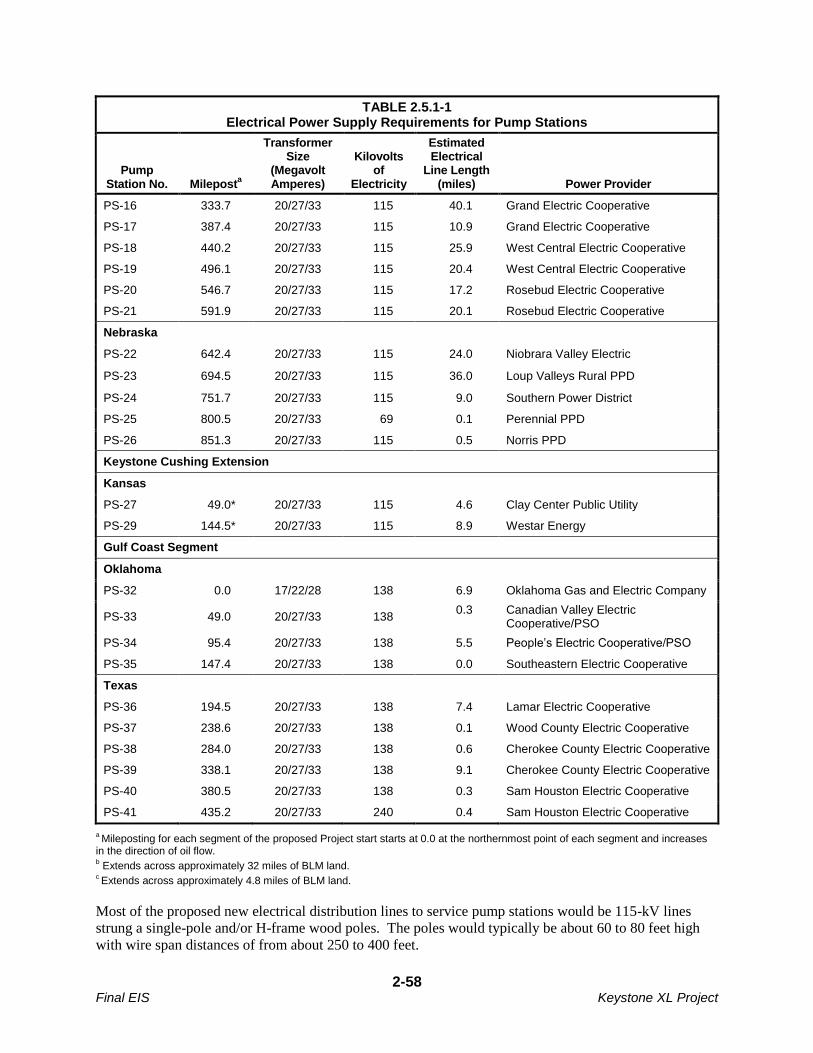
2-58 Final EIS Keystone XL Project
TABLE 2.5.1-1 Electrical Power Supply Requirements for Pump Stations
Pump Station No. Milepost
a
Transformer Size
(Megavolt Amperes)
Kilovolts of
Electricity
Estimated Electrical
Line Length (miles) Power Provider
PS-16 333.7 20/27/33 115 40.1 Grand Electric Cooperative
PS-17 387.4 20/27/33 115 10.9 Grand Electric Cooperative
PS-18 440.2 20/27/33 115 25.9 West Central Electric Cooperative
PS-19 496.1 20/27/33 115 20.4 West Central Electric Cooperative
PS-20 546.7 20/27/33 115 17.2 Rosebud Electric Cooperative
PS-21 591.9 20/27/33 115 20.1 Rosebud Electric Cooperative
Nebraska
PS-22 642.4 20/27/33 115 24.0 Niobrara Valley Electric
PS-23 694.5 20/27/33 115 36.0 Loup Valleys Rural PPD
PS-24 751.7 20/27/33 115 9.0 Southern Power District
PS-25 800.5 20/27/33 69 0.1 Perennial PPD
PS-26 851.3 20/27/33 115 0.5 Norris PPD
Keystone Cushing Extension
Kansas
PS-27 49.0* 20/27/33 115 4.6 Clay Center Public Utility
PS-29 144.5* 20/27/33 115 8.9 Westar Energy
Gulf Coast Segment
Oklahoma
PS-32 0.0 17/22/28 138 6.9 Oklahoma Gas and Electric Company
PS-33 49.0 20/27/33 138 0.3 Canadian Valley Electric
Cooperative/PSO
PS-34 95.4 20/27/33 138 5.5 People’s Electric Cooperative/PSO
PS-35 147.4 20/27/33 138 0.0 Southeastern Electric Cooperative
Texas
PS-36 194.5 20/27/33 138 7.4 Lamar Electric Cooperative
PS-37 238.6 20/27/33 138 0.1 Wood County Electric Cooperative
PS-38 284.0 20/27/33 138 0.6 Cherokee County Electric Cooperative
PS-39 338.1 20/27/33 138 9.1 Cherokee County Electric Cooperative
PS-40 380.5 20/27/33 138 0.3 Sam Houston Electric Cooperative
PS-41 435.2 20/27/33 240 0.4 Sam Houston Electric Cooperative
a Mileposting for each segment of the proposed Project start starts at 0.0 at the northernmost point of each segment and increases
in the direction of oil flow. b Extends across approximately 32 miles of BLM land.
c Extends across approximately 4.8 miles of BLM land.
Most of the proposed new electrical distribution lines to service pump stations would be 115-kV lines
strung a single-pole and/or H-frame wood poles. The poles would typically be about 60 to 80 feet high
with wire span distances of from about 250 to 400 feet.
2-59 Final EIS Keystone XL Project
Each pump station would have a substation integrated into the general pump station layout. In some cases
(pump stations 36 and 41), Keystone would share pump station land with the local utility for the
installation of their substation. Sharing of substation land at the pump station would allow the utility to
provide a second transformer to provide service to the rural customers in the area.
The exact location of each substation cannot be identified at this time because the electrical supply lines
would access pump stations from different alignments. Each substation footprint would be approximately
1 to 1.5 acres and is included in the total land size of each pump station. The actual size of a substation
would be dictated by the specific design and size requirements of the local power supply company, the
capacity of the power supply lines connected to each specific pump station, and the associated equipment.
Figures 2.2.3-1 and 2.2.3-2 provide typical layouts for substations and pump stations.
Other electrical power requirements, such as power for MLVs, would be supplied from distribution
service drops from adjacent distribution power lines with voltage below 69 kV. Each distribution service
drop would typically be less than 200 feet long, and would require the installation of one or two poles and
a transformer. The electric utility would typically install a pole-mounted transformer within 200 feet of
the valve site location. However, in some cases the electric utility would install the transformer on an
existing pole which would be more than 200 feet from the valve site. The decision on where the
transformer pole would be located would generally be based on the most economical installation. For
example, MLVs north of the Milk River in Montana would be supplied from transformers on poles along
small lines that currently supply power to irrigation systems. Upon completion of the new service drops,
the electrical power providers would restore the work area as required, in accordance with local permits.
Preliminary routing for new electrical distribution lines was established in consultation with each utility
company. Where practicable, these preliminary routes were along existing county roads, section lines, or
field edges, to minimize interference with adjacent agricultural lands. The routes are subject to change as
pumping station supply requirements are further reviewed with power providers and in some cases, as a
result of environmental review of the routes by the agencies with jurisdiction.
Electromagnetic induction can occur from power lines, which can cause noise, radio, and television
interference. This potential interference would be mitigated by siting the power line away from
residences (500 feet minimum, if possible) and by routing the power line to reduce parallel metallic
interferences.
Power line Radio Frequency Interference (RFI) is usually caused by sparking (arcs) which is typically
caused by loose hardware. The power provider design uses spring washers to keep hardware tight to
minimize arcing and conductor supports use specialized clamps to keep the conductor and support clamps
firmly connected to further reduce the potential for arcing. Defective lightning arrestors could also
contribute to RFI. The power providers would use a static conductor at the top of the pole to mitigate
lightning-caused flashovers. Lightning arrestors would be limited to the stations where major equipment
is located.
The radio communication systems at the proposed Project facilities would operate on specific frequencies
licensed by the Federal Communications Commission (FCC). This would reduce the risk of any
interference with radio, television, or any other communication system in the area.
Several Montana residents expressed concern about the source of energy for the electricity provided by
utility companies to power the pump stations and mainline valves in Montana. Some Montana residents
also asked about the potential for residential rates to increase.
Electric cooperatives (coops) in Montana obtain electricity from a variety of sources, including coal-fired
power plants, hydroelectric plants, and at wind farms in the area. Many coops have service agreements

2-60 Final EIS Keystone XL Project
with Western Area Power Administration (Western), Bonneville Power Administration (BPA), PPL
Montana, and Basin Electric Power Cooperative, some of which likely results in electrical energy being
transported to Montana from many distant and varied sources. This energy flows primarily across
transmission owned by Western and NorthWestern Energy to delivery points within the cooperative
systems. The energy is delivered to the members/consumers through distribution lines, substations, and
other related infrastructure.
As a result, it is not possible to identify the specific facilities or the specific sources of energy that would
be used to generate the electricity that would be used at the pump stations and mainline valves in
Montana. Each of the coops involved has agreed to provide the necessary power and would likely request
the additional power from their current providers. Any increase in power generation at the plants
providing that power would have to be conducted in compliance with environmental regulations. If
additional nonrenewable resources are needed to generate the additional, the provision of those resources
would also have to be accomplished consistent with regulatory requirements.
2.5.1.2 Construction Procedures
All distribution lines and substations would be installed and operated by local power providers. This
work would include ROW acquisition, ROW clearing, construction, site restoration, cleanup, and
obtaining any necessary permits, approvals, or authorizations from federal, state, and local governments.
The proposed distribution lines would require a 100-foot-wide construction ROW and an 80-foot-wide
permanent ROW. Each power provider would develop detailed power line construction procedures to
address site specific conditions. In general, construction of the electrical distribution lines would involve
the following:
ROW Acquisition/Easements: The electric power provider would obtain any necessary easements.
ROW Clearing: Limited clearing would be required along existing roads in native and improved grasslands and croplands. Either tree trimming or tree removal would be conducted to provide adequate clearance between the conductors and underlying vegetation.
Power Line Construction: Power line poles and associated structures would be delivered on flatbed trucks. Radial arm diggers would typically be used to excavate the required holes. Poles would be either wood or steel and would be directly embedded into the excavated holes using a mobile crane or picker truck where appropriate. Anchors may be required at angles and dead ends.
Stringing: After the power line poles are in place, conductors (wires) would be strung between them. Pulling or reeling areas would be needed for installation of the conductor wires which would be attached to the poles using porcelain or fiberglass insulators.
Restoration: After completion of distribution line construction, the disturbed areas would be
restored. All litter and other remaining materials would be removed from the construction areas and
disposed of in accordance with regulatory requirements. Preconstruction contours would be
restored as closely as possible and reseeding would follow landowner requirements.
2.5.2 Big Bend to Witten 230-kV Transmission Line
2.5.2.1 Overview
After receipt of information on the power requirements for the proposed pump stations in South Dakota,
the Western Area Power Administration (Western) conducted a joint system engineering study to
determine system reliability under the proposed loads at full Project electrical energy consumption. The
joint system engineering studies determined that a 230-kV transmission line originating at the Fort
Thompson/Big Bend area and extending south to the existing Witten Substation would be required to
2-61 Final EIS Keystone XL Project
support voltage requirements for pump stations 20 and 21 in the Witten area when the proposed Project is
operating at maximum capacity.
To address this requirement, Western proposes to convert the existing Big Bend-Fort Thompson No. 2,
230-kV transmission line turning structure, located on the south side of the dam, to a double-circuit
structure. Western would then construct approximately 2.1 miles of new double-circuit transmission line
south to a new substation, tentatively named Big Bend Substation, which would also be constructed by
Western. The new switchyard/substation would be a 3-breaker ring bus configuration, expandable to a
breaker and a half configuration. The new 2.1-mile-long double-circuit 230-kV transmission line would
be owned, constructed, and operated by Western. After construction, the ownership of the Big Bend
Substation would be transferred to the Basin Electric Power Cooperative (BEPC) which would then own
and operate it. Western would complete design of the new substation and double-circuit transmission line
in 2012 and would begin construction in the spring of 2013.
BEPC proposes to construct and operate a new 230-kV transmission line from the proposed new Big
Bend Substation to the existing Witten Substation owned by Rosebud Electric Cooperative. The new Big
Bend Substation and approximately 70-mile-long Big Bend to Witten 230-kV transmission line would
assure future electric power requirements at pump stations 20 and 21 would be met without degrading
system reliability when the proposed Project is operating at maximum capacity. The new Big Bend to
Witten 230-kV transmission line would be built, owned, and operated by BEPC. The Witten Substation
would also need to be expanded to accommodate the new switching equipment associated with the Big
Bend to Witten 230-kV transmission line.
A SCADA system would interconnect the substations. Hardwire system communications would utilize
fiber optics within the Optical Overhead Ground Wire between the substations. Microwave
communications equipment would be installed for SCADA redundancy and to facilitate voice and data
communications by field personnel. Additional communications facilities may also be needed. The
proposed substation and transmission line projects would be in Lyman and Tripp counties in south-central
South Dakota. The Big Bend Dam is in Lyman County, close to the city of Fort Thompson. The Witten
Substation is in Tripp County near the city of Witten.
Western and BEPC identified two alternative corridors for the proposed Big Bend to Witten transmission
line project, and there are nine route options within each corridor between the Big Bend and Witten
substations. Initially, a 6-mile-wide corridor, Alternative Corridor A, was identified between an existing
substation on the transmission grid and a proposed new substation at Big Bend. BEPC and Western then
identified five preliminary alternative routes for the transmission line within Corridor A (see Figure 2.5.2-
1); the five alternatives are the Western Alternative and Alternatives BEPC-A through BEPC-D. BEPC,
Western, and the Lower Brule Reservation also identified Alternative Corridor B, which is also a 6-mile-
wide corridor. This corridor follows a similar path from the existing Witten Substation to the proposed
Big Bend Substation but with deviations in the southeast near Winner and the northeast near Reliance.
Corridor B was further developed into four preliminary alternative routings for the transmission line (see
Figure 2.5.2-1); the four alternatives are Alternatives BEPC-E through BEPC-H. The alternatives within
both Corridor A and Corridor B cross the Lower Brule Reservation and connect with an existing
transmission line near the Big Bend Dam.
BEPC is pursuing financing for the transmission line project from the Rural Utilities Service (RUS).
Under the RUS regulations for implementation of NEPA, an Environmental Assessment (EA) must be
prepared to assess potential environmental impacts of the proposed action. BEPC has indicated that RUS
would serve as the lead agency for NEPA, and Western would serve as a cooperating agency. In early
2011, BEPC informed DOS that it would contract with an environmental consultant to prepare a Macro
Corridor Study and an Alternative Evaluation Study prior to initiating scoping for the EA. Based on the

2-62 Final EIS Keystone XL Project
current schedule, BEPC anticipates that all project permits and approvals would be in place by the end of
2012, and construction could begin in early 2013, assuming that there would be a need for the
transmission line at the end of the construction period.
2.5.2.2 Construction Procedures
The proposed transmission line would be constructed within a 125-foot-wide ROW. The specific
structure type has not been determined, but would be either single- or two-pole structures.
All substation and switchyard work, including the placement of concrete foundations, erecting support
structures, construction of control buildings, and the installation of electrical equipment would take place
within secured areas. The proposed substation site at Big Bend and the expansion area at Witten would
be cleared and leveled. Aggregate would be spread throughout undeveloped areas within the substation
sites. Topsoil would be segregated from underlying soils and redistributed on disturbed areas outside the
substation security fences. Soil erosion would be minimized during construction using BMPs. Substation
components would be hauled to the site on local highways and roads and off-loaded using cranes and
similar equipment. Concrete and aggregate from local sources would be hauled to the site by truck.
The impacts of construction and operation of the transmission line alternatives are generally addressed in
Section 3.0 the EIS. However, DOS, Western, and the other cooperating agencies do not have sufficient
design and construction information to establish an agency-preferred alternative for the proposed
transmission line project. An additional and separate NEPA environmental review of the alternatives to
the proposed transmission line will be conducted after the alternative routes are further defined. The
design and environmental review of the proposed 230-kV transmission line are on a different schedule
than the pipeline system itself. Regional transmission system reliability concerns are not associated with
the initial operation of the proposed pipeline pump stations, but only for future operation at the maximum
throughput volume of 830,000 bpd.
2.5.3 Bakken Marketlink Project
Keystone Marketlink, LLC (Keystone Marketlink), a wholly owned subsidiary of TransCanada Pipelines
Limited, is proposing to construct and operate the Bakken Marketlink Project. That project would include
construction of facilities to provide crude oil transportation service from near Baker, Montana to Cushing,
Oklahoma via the proposed Project and from Cushing to delivery points at Nederland and Moore Junction
(east of Houston), Texas, via the proposed Project. After a successful Open Season, Keystone Marketlink
obtained commitments for transport of approximately 65,000 bpd of crude oil through the Bakken
Marketlink Project. The project could deliver up to 100,000 bpd to the proposed Project depending on
ultimate shipper commitments. Baker is near many existing and proposed crude oil gathering systems,
pipelines, and crude oil storage tanks, and the Bakken Marketlink Project would provide direct access to
PADD II and PADD III markets. The announced target in-service date for the Bakken Marketlink Project
is the first quarter of 2013.
The project would consist of piping, booster pumps, meter manifolds and two tank terminals; one
terminal would be near Plevna and Baker, Montana, and the second would be at the proposed Cushing
tank farm. The Bakken Marketlink facilities would include two, 250,000-barrel tanks that would be used
to accumulate crude from connecting third-party pipelines and terminals and a 100,000-barrel tank that
would be use for operational purposes (see Figure 2.5.3-1). The facilities would also include a proposed 5
mile long pipeline that would initiate at an existing Montana tank farm facility in Township 7N Range
58E Section 4. The project is still in the preliminary stages of evaluating the options regarding the
routing of this proposed pipeline.
2-63 Final EIS Keystone XL Project
The Bakken Marketlink Project facilities at the Cushing tank farm would include two, 250,000-barrel
tanks that would be used for batch deliveries from the Baker facilities (see Figure 2.5.3-2). Figure 2.5.3-3
is a plot plan for the tank farm near Cushing that includes the Bakken Marketlink tanks, the Cushing
Marketlink tanks, and two portions of the proposed Keystone XL Project (the Cushing tank farm and
pump station 32).
Crude oil in the Bakken Marketlink storage tanks at the Cushing tank farm would either be pumped to the
Keystone XL pipeline for delivery to PADD III or delivered to other pipelines and tank farms near
Cushing. The Cushing tank farm would be near many pipelines, storage facilities, and refineries since
Cushing is a major crude oil marketing, refining, and pipeline hub that provides shippers with many
delivery options and market access. Delivery of the crude oil to Nederland would be as described in this
EIS for the proposed Project.
The Bakken Marketlink Project would provide the first direct link between the prolific Bakken crude oil
producing region and key U.S. markets near Cushing and the in the Gulf Coast area, which is the largest
refining market in North America.
2.5.4 Cushing Marketlink Project
Keystone Marketlink also plans to construct and operate the Cushing Marketlink Project. The Cushing
Marketlink Project would include construction and operation of facilities within the boundaries of the
proposed Keystone XL Cushing tank farm. From there, crude oil would be transported by the proposed
Keystone XL Project to delivery points at Nederland and Moore Junction (east of Houston), Texas. After
a successful Open Season in late 2010, Keystone Marketlink obtained sufficient commitments to proceed
with the project, which will have the ability to deliver approximately 150,000 barrels of crude oil per day
to the proposed Keystone Xl pipeline. On August 15, 2011, Keystone Marketlink initiated a second
binding Open Season to obtain additional firm commitments from interested parties for the planned
project.
The Cushing Marketlink facilities at the proposed Cushing tank farm site would be adjacent to the
Cushing Oil Terminal, a key pipeline transportation and crude oil storage hub with over 50 million barrels
of storage capacity. As a result, the Cushing Marketlink Project would be near many pipelines and
storage facilities that could ship crude oil to the Cushing Marketlink facilities. The Cushing Marketlink
Project is expected to alleviate current pipeline constraints from the Cushing area and provide shippers
with a new transportation option from the Cushing market to the U.S. Gulf Coast. The announced target
in-service date for the Cushing Marketlink Project is the first quarter of 2013.
The Cushing Marketlink Project would include construction and operation of receipt custody transfer
metering systems and batch accumulation tankage consisting of two, 350,000 barrel tanks, with one tank
dedicated for light sweet crude. The tanks would be located within the proposed Project’s Cushing tank
farm property, which also would house pump station 32 of the proposed Project (see Figure 2.5.3-3) and
the storage tanks for the planned Bakken Marketlink storage tanks (described in Section 2.5.3). The tanks
would accumulate batches from existing third-party pipelines and terminals for transportation to the U.S.
Gulf Coast on the proposed Project. Delivery of the crude oil to delivery points in Texas would be as
described in this EIS for the proposed Project.
2-64 Final EIS Keystone XL Project
2.6 FUTURE PLANS AND PROJECT DECOMMISSIONING
2.6.1 Future Plans
2.6.1.1 Proposed Project
As proposed, the Project would initially have a nominal transport capacity of approximately 700,000 bpd
of crude oil. By increasing the capacity of the pump stations in the future, Keystone could transport up to
830,000 bpd of crude oil through the pipeline. Should Keystone decide to increase pumping capacity to
8300,000 bpd at a later date, the necessary pump station upgrades would be implemented in accordance
with then-applicable permits, approvals, codes, and regulations.
2.6.1.2 Other Related Facilities
After the draft EIS was issued, plans were announced for future development of two projects that could
transport crude oil to the proposed Project from producers in North Dakota and Montana and from
producers in the Cushing, Oklahoma area. Those planned projects are the Bakken Marketlink Project and
the Cushing Marketlink Project. Those projects are considered connected actions for the purpose of the
EIS and are described using all available information in Sections 2.5.3 and 2.5.4.
2.6.2 Decommissioning of the Proposed Project
Many commenters requested that the EIS provide additional information about the anticipated life of the
proposed Project and a description of how the proposed Project would be decommissioned at the end of
its useful life. This section has been revised in response to those requests.
2.6.2.1 Project Life
Keystone used a design life of 50 years to develop the engineering standards for the proposed Project.
However, with implementation of the pipeline integrity management plan, the 57 Project-specific Special
Conditions developed by PHMSA (see Appendix U), and an operations and maintenance program as
described above, Keystone anticipates that the life of the proposed Project would be much longer. Many
other pipeline companies have safely extended the duration of pipeline systems by replacing sections of
pipe after finding anomalies and by replacing or upgrading equipment and facilities at pump stations. As
a result, it is not possible to identify a specific number of years that the proposed Project may be in
service.
2.6.2.2 Decommissioning
PHMSA has requirements that apply to the decommissioning of crude oil pipelines in 49 CFR Section
195.402(c)(10) and in 49 CFR 195.59 and 195.402. These regulations require that for hazardous liquid
pipelines, the procedural manuals for operations, maintenance, and emergencies must include procedures
for abandonment, including safe disconnection from an operating pipeline system, purging of
combustibles, and sealing abandoned facilities left in place to minimize safety and environmental hazards
(49 CFR 195.402). Further, these regulations require that for each abandoned onshore pipeline facility
that crosses over, under, or through a commercially navigable waterway, the last operator of that facility
must file a report upon abandonment of that facility. It further states that “. . . operators must submit the
date of abandonment, diameter, method of abandonment, and certification that, to the best of the
operator's knowledge, all of the reasonably available information requested was provided and, to the best
of the operator's knowledge, the abandonment was completed in accordance with applicable laws . . . The
information in the report must contain all reasonably available information related to the facility,
2-65 Final EIS Keystone XL Project
including information in the possession of a third party. The report must contain the location, size, date,
method of abandonment, and a certification that the facility has been abandoned in accordance with all
applicable laws.”
TransCanada (the parent company of Keystone) would adopt operating procedures to address these
requirements for the proposed Project as they have for previous pipeline projects including the existing
Keystone Pipeline. TransCanada typically does not abandon large diameter pipelines but generally idles
or deactivates pipe as market conditions dictate. This allows a dormant pipeline to be reactivated or
converted to another purpose in the future. When a pipeline or a segment of a pipeline is idled or
deactivated, the pipe generally is purged of its contents, filed with an inert gas, and left in place with
warning signage intact. Cathodic protection would likely be left functional as would other integrity
measures such as periodic inspections under the integrity management plan.
The proposed Project pipeline would traverse approximately 44.6 miles of federal land under the
management and jurisdiction of the BLM. The majority of the federal land is in the state of Montana.
The portion of the proposed Project that would cross BLM-administered land would be subject to the
pipeline decommissioning and abandonment requirements stipulated in the BLM right-of-way grants and
permanent easement permits. These requirements are:
“1. Boundary adjustments in Oil and Gas [user entry (lease or unit number)] shall automatically
amend this right-of-way to include that portion of the facility no longer contained within the
above described [user entry]. In the event an automatic amendment to this right-of way grant, the
prior on-lease/unit conditions of approval of this facility will not be affected even though they
would now apply to facilities outside of the lease/unit as a result of a boundary adjustment. Rental
fees, if appropriate shall be recalculated based on the conditions of this grant and the regulations
in effect at the time of an automatic amendment.
2. Prior to termination of the right-of-way, the holder shall contact the authorized officer to
arrange a predetermination conference. This conference will be held to review the termination
provisions of the grant.
3. [user entry, period of time] prior to termination of the right-of-way, the holder shall contact the
authorized officer to arrange a joint inspection of the right-of-way. This inspection will be held to
agree to an acceptable termination (and rehabilitation) plan. This plan shall include, but is not
limited to, removal of facilities, drainage structures, or surface material, recontouring, topsoiling,
or seeding. The authorized officer must approve the plan in writing prior to the holder’s
commencement of any termination activities.”
The right-of-way (ROW) grant on federal lands under the management of BLM for the proposed Project
would have a maximum term not to exceed of 30 years. For the proposed Project to extend beyond 30
years, the approved ROW grant would require a renewal authorization-certification decision by BLM.
This decision would be considered a federal action subject to the requirements of NEPA. As a result, a
decision to renew-certify the ROW grant to allow the proposed Project lifetime to remain in place beyond
30 years would be accompanied by an environmental analysis similar to the analysis required for the
initial ROW grant. This process occurred on the Alyeska Oil Pipeline in Alaska. The initial ROW grant
for federal lands crossed by that project extended from 1974 to 2004, and BLM and the State of Alaska
through the Joint Pipeline Office required an EIS addressing continued operation of that project prior to
certifying a new ROW grant with a maximum term of 30 years. It is likely that the future environmental
assessment that would be required by BLM to renew-certify the approved ROW agreement grant for the
proposed Project would include a review of the environmental effects of the continued operation of the
entire proposed Project, since operations on non-federal lands would be connected actions to the renewal-
2-66 Final EIS Keystone XL Project
certification action on federal lands. Therefore, any operations or decommissioning that would occur
beyond the initial 30-year ROW grant would be subject to extensive federal environmental review.
In Texas, Section 111.025 of the Texas Natural Resources Code would apply to decommissioning of the
proposed Project. The provisions of the code are:
“(a) No common carrier may abandon any of its connections or lines except under authority of a
permit granted by the commission or with written consent of the owner or duly authorized agent
of the wells to which connections are made.
(b) Before granting a permit to abandon any connection, the commission shall issue proper notice
and hold a hearing as provided by law.”
While there are no state regulations applicable to pipeline decommissioning in Montana, South Dakota,
Nebraska, or Oklahoma, environmental specifications developed by Montana DEQ that would address
reclamation of areas disturbed during abandonment would be a condition of the grant of a certificate
under MFSA.
Decommissioning activities would have to be conducted consistent with all applicable regulatory
requirements that are in place at the time of decommissioning. Since regulations at the federal, state, and
local level change over time, it would be highly speculative to project what regulatory framework would
apply to Project decommissioning at the end of the useful life of the proposed Project more than 50 years
in the future.
Prior to decommissioning the Project, Keystone would identify the decommissioning procedures it would
use along each portion of the route, identify the regulations it would be required to comply with, and
submit applications for the appropriate environmental permits. At that point, Keystone and the issuing
agencies would address the environmental impacts of implementation of the decommissioning procedures
and identify the mitigation measures required to avoid or minimize impacts.
It is likely that after decommissioning there would be fewer land use restrictions than during operation of
the proposed Project since either the ROW would no longer have strict encroachment limitations for
protection of the purged pipeline, or the pipeline may have been removed and there would no longer be
limitations of use of the former ROW.
As noted above, PHMSA regulations require that hazardous liquids pipelines be purged of combustibles
prior to decommissioning. Therefore the potential for the release of contaminants from the
decommissioned pipeline would be negligible.
2-67 Final EIS Keystone XL Project
2.7 REFERENCES
Accufacts, Inc. 2007. Recommended Leak Detection Methods for the Keystone Pipeline in the Vicinity
of the Fordville Aquifer, September. Website (http://www.psc.nd.gov/database/documents/06-
0421/165-010.pdf) accessed August 12, 2011.
Griesser, S. 2011. BakkenLink Pipeline LLC. Personal communication to Bill Staeger, Cardno
ENTRIX, February, 2011.
PHMSA. See Pipeline and Hazardous Materials Safety Administration.
Pipeline and Hazardous Materials Safety Administration (PHMSA). 2007. Leak Detection Technology
Study. As Required by The Pipeline Inspection, Protection, Enforcement and Safety (PIPES) Act of
2006 (Pub.L. No.109-468). December 31, 2007.
Purvin & Gertz. 2009. Western Canadian Crude Supply and Markets. A report prepared for
TransCanada Keystone Pipeline GP LMTD.

2-68 Final EIS Keystone XL Project
This page intentionally left blank.