
13VTL100
104
13VT-L100/150 13VT-CL10 CONTENTS Page » IMPORTANT SERVICE SAFETY PRECAUTION .................................................................................... 2 » ELECTRICAL SPECIFICATIONS ............................................................................................................ 6 » LOCATION OF USER’S CONTROL ........................................................................................................ 7 » DISASSEMBLY AND REASSEMBLY ...................................................................................................... 9 » INSTALLATION AND SERVICE INSTRUCTIONS ................................................................................. 12 » PRECAUTIONS IN REASSEMBLING ................................................................................................... 17 » FUNCTION OF MAJOR MECHANICAL PARTS .................................................................................... 18 » ADJUSTMENT, REPLACEMENT AND ASSEMBLY OF MECHANICAL UNITS ................................... 20 » ADJUSTMENT OF THE VCR ELECTRICAL CIRCUITRY ..................................................................... 40 » TROUBLESHOOTING ........................................................................................................................... 42 » CHASSIS LAYOUT ................................................................................................................................. 54 » BLOCK DIAGRAM OF TV SECTION ..................................................................................................... 56 » BLOCK DIAGRAM OF VCR SECTION .................................................................................................. 58 » OVERALL SCHEMATIC DIAGRAM ....................................................................................................... 68 » DESCRIPTION OF SCHEMATIC DIAGRAM ......................................................................................... 70 » PRINTED WIRING BOARD ASSEMBLIES ........................................................................................... 82 » REPLACEMENT PARTS LIST ............................................................................................................... 89 » PACKING OF THE SET ....................................................................................................................... 103 In the interests of user-safety (Required by safety regulations in some countries ) the set should be restored to its original condition and only parts identical to those specified should be used. MODELS TV/VCR COMBINATION Chassis No. B97B 13VT-L100/150 13VT-CL10 SERVICE MANUAL This document has been published to be used for after sales service only. The contents are subject to change without notice. SHARP CORPORATION SERVICE MANUAL MODELS 13VT-L100/150/CL10 S29D113VTL100 TV/VCR COMBINATION
-
Upload
pedro-gabriel -
Category
Documents
-
view
54 -
download
6
Transcript of 13VTL100

1
13VT-L100/15013VT-CL10
13VT-L100/15013VT-CL10
CONTENTS
Page» IMPORTANT SERVICE SAFETY PRECAUTION .................................................................................... 2» ELECTRICAL SPECIFICATIONS ............................................................................................................ 6» LOCATION OF USER’S CONTROL ........................................................................................................ 7» DISASSEMBLY AND REASSEMBLY ...................................................................................................... 9» INSTALLATION AND SERVICE INSTRUCTIONS ................................................................................. 12» PRECAUTIONS IN REASSEMBLING ................................................................................................... 17» FUNCTION OF MAJOR MECHANICAL PARTS.................................................................................... 18» ADJUSTMENT, REPLACEMENT AND ASSEMBLY OF MECHANICAL UNITS ...................................20» ADJUSTMENT OF THE VCR ELECTRICAL CIRCUITRY ..................................................................... 40» TROUBLESHOOTING ........................................................................................................................... 42» CHASSIS LAYOUT................................................................................................................................. 54» BLOCK DIAGRAM OF TV SECTION ..................................................................................................... 56» BLOCK DIAGRAM OF VCR SECTION .................................................................................................. 58» OVERALL SCHEMATIC DIAGRAM ....................................................................................................... 68» DESCRIPTION OF SCHEMATIC DIAGRAM ......................................................................................... 70» PRINTED WIRING BOARD ASSEMBLIES ........................................................................................... 82» REPLACEMENT PARTS LIST ............................................................................................................... 89» PACKING OF THE SET ....................................................................................................................... 103
In the interests of user-safety (Required by safety regulations in some countries ) the set should be restored to itsoriginal condition and only parts identical to those specified should be used.
MODELS
TV/VCR COMBINATION
Chassis No. B97B
13VT-L100/15013VT-CL10
SERVICE MANUAL
This document has been published to be used forafter sales service only.The contents are subject to change without notice.
SHARP CORPORATION
SE
RV
ICE
MA
NU
AL
MO
DE
LS 13V
T-L100/150/C
L10
S29D113VTL100
TV
/VC
R C
OM
BIN
AT
ION

2
13VT-L100/15013VT-CL10
IMPORTANT SERVICE SAFETY PRECAUTIONService work should be performed only by qualified service technicians who are thoroughlyfamiliar with all safety checks and servicing guidelines which follow:
SERVICING OF HIGH VOLTAGE SYSTEM ANDPICTURE TUBE
When servicing the high voltage system, re-move the static charge by connecting a 10kohm resistor in series with an insulated wire(such as a test probe) between the picturetube ground and the anode lead. (AC linecord should be disconnected from AC out-let.)
1. Note that the picture tube in this receiver employsintegral implosion protection.
2. Replace with tube of the same type number forcontinued safety.
3. Do not lift picture tube by the neck.4. Handle the picture tube only when wearing
shatterproof goggles and after discharging the highvoltage anode completely.
WARNING
1. For continued safety, no modification of any circuitshould be attempted.
2. Disconnect AC power before servicing.3. Semiconductor heat sinks are potential shock hazards
when the chassis is operating.4. The chassis in this receiver has two ground systems
which are separated by insulation material. The non-isolated (hot) ground system is for the B+ voltageregulator circuit and the horizontal output circuit.Theisolated ground system is for the low B+ DC voltagesand the secondary circuit of the high voltagetransformer.To prevent electrical shock use an isolationtransformer between the line cord and powerreceptacle, when servicing this chassis.
X-RADIATION AND HIGH VOLTAGE LIMITS
1. Be sure all service personnel are aware of theprocedures and instructions covering X-radiation. Theonly potential source of X-ray in current solid state TVreceivers is the picture tube. However, the picture tubedoes not emit measurable X-Ray radiation if the highvoltage is as specified in the "High Voltage Check"instructions.It is only when high voltage is excessive that X-radiation is capable of penetrating the shell of thepicture tube including the lead in glass material. Theimportant precaution is to keep the high voltage belowthe maximum level specified.
2. It is essential that servicepersonel have available atall times an accurate high voltage meter.The calibration of this meter should be checkedperiodically.
3. High voltage should always be kept at the rated value-no higher. Operation at higher voltages may cause afailure of the picture tube or high voltage circuitryand;also, under certain conditions, may produceradiation that exceeds specifications.
4. When the high voltage regulator is operating properlythere is no possibility of an X-radiation problem. Everytime a color chassis is serviced, the brightnessshould be tested while monitoring the high voltagewith a meter to be certain that the high voltage doesnot exceed the specified value and that it is regulatingcorrectly.
5. Do not use a picture tube other than that specified ormake unrecommended circuit modifications to the highvoltage circuitry.
6. When trouble shooting and taking test measurementson a receiver with excessive high voltage, avoid beingunnecessarily close to the receiver.Do not operate the receiver longer than is necessaryto locate the cause of excessive voltage.
CAUTION: FOR CONTINUEDPROTECTION AGAINST ARISKOF FIRE, REPLACEONLY WITH SAME TYPE 4A-125V FUSE.
4A 125V
3
13VT-L100/15013VT-CL10
BEFORE RETURNING THE RECEIVER
(Fire & Shock Hazard)
Before returning the receiver to the user, perform thefollowing safety checks.
123456789012345678901234567890121234567890123456789012345678901212345678901234567890123456789012123412345678901234567890123456789012123456789012345678901234567890121234567890123456789012345678901212341234567890123456789012345678901212345678901234567890123456789012123456789012345678901234567890121234
SAFETY NOTICE
Many electrical and mechanical parts in televisionreceivers have special safety-related characteristics.These characteristics are often not evident from visualinspection, nor can protection afforded by them benecessarily increased by using replacement componentsrated for higher voltage, wattage, etc.Replacement parts which have special safetycharacteristics are identified in this manual; electricalcomponents having such features are identified by " å "and shaded areas in the Replacement Parts Lists andSchematic Diagrams.
ACVOLTMETER
1.5k ohm10W
0.15µFTEST PROBE
TO EXPOSEDMETAL PARTS
CONNECT TOKNOWN EARTHGROUND
1. Inspect all lead dress to make certain that leads arenot pinched or that hardware is not lodged betweenthe chassis and other metal parts in the receiver.
2. Inspect all protective devices such as non-metalliccontrol knobs, insulating materials, cabinet backs,adjustment and compartment covers or shields,isolation resistor-capacity networks, mechanicalinsulators, etc.
3. To be sure that no shock hazard exists, check forleakage current in the following manner.
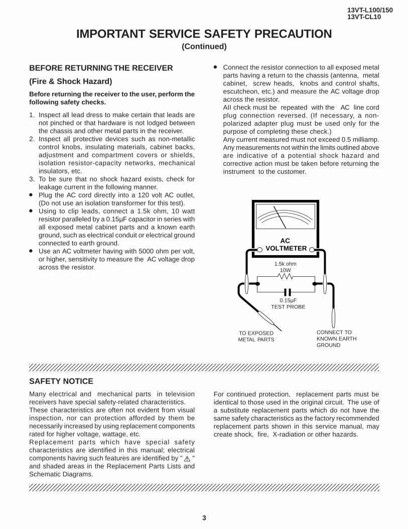
» Plug the AC cord directly into a 120 volt AC outlet,(Do not use an isolation transformer for this test).
» Using to clip leads, connect a 1.5k ohm, 10 wattresistor paralleled by a 0.15µF capacitor in series withall exposed metal cabinet parts and a known earthground, such as electrical conduit or electrical groundconnected to earth ground.
» Use an AC voltmeter having with 5000 ohm per volt,or higher, sensitivity to measure the AC voltage dropacross the resistor.
IMPORTANT SERVICE SAFETY PRECAUTION(Continued)
123456789012345678901234567890121234567890123456789012345678901212345678901234567890123456789012123412345678901234567890123456789012123456789012345678901234567890121234567890123456789012345678901212341234567890123456789012345678901212345678901234567890123456789012123456789012345678901234567890121234
» Connect the resistor connection to all exposed metalparts having a return to the chassis (antenna, metalcabinet, screw heads, knobs and control shafts,escutcheon, etc.) and measure the AC voltage dropacross the resistor.AII check must be repeated with the AC line cordplug connection reversed. (If necessary, a non-polarized adapter plug must be used only for thepurpose of completing these check.)Any current measured must not exceed 0.5 milliamp.Any measurements not within the limits outlined aboveare indicative of a potential shock hazard andcorrective action must be taken before returning theinstrument to the customer.
For continued protection, replacement parts must beidentical to those used in the original circuit. The use ofa substitute replacement parts which do not have thesame safety characteristics as the factory recommendedreplacement parts shown in this service manual, maycreate shock, fire, X-radiation or other hazards.
4
13VT-L100/15013VT-CL10
PRECAUTIONS A PRENDRE LORS DE LA REPARATIONNe peut effectuer la réparation qu' un technicien spécialisé qui s'est parfaitement accoutuméà toute vérification de sécurité et aux conseils suivants.
AVERTISSEMENT
1. N'entreprendre aucune modification de tout circuit.C'est dangereux.
2. Débrancher le récepteur avant toute réparation.3. Les déversoirs thermiques à semi-conducteurs
peuvent présenter un danger de choc électriquelorsque le réceqteur est en marche.
4. Le châssis de ce récepteur a deux systèmes de miseà la terre qui sont séparés par un matériau isolant. Lesystème de mise à la terre non-isolée (chaud) est pourle circuit du régulateur de tension B+ et le circuit desortie horizontale. Le système de mise à la terre isoléest pour les basses tensions C. C. B+ et le circuitsecondaire du transformateur de haute tension.
REPARATION DU SYSTEME A HAUTE TEN-SION ET DU TUBE-IMAGE
Lors de la réparation de ce systéme,supprimer la charge statique en branchantune résistance de 10 k en série avec un filisolé (comme une sonde d'essai) entre lamise à la terre du tube-image et le fil d'anodel.(Le corden d'alimentation doit être retiré dela prise murale.)
1. Il est à noter que le tube-image de ce récepteur estintégralement protégé contre l'implosion.
2. Par mesure de sécurité, changer le tube-image pourun tube du même numéro de type.
3. Ne pas lever le tube-image par son col.4. Ne manipuler le tube-image qu'en porant des lunettes
incassables et qu'après avoir déchargé totalement lahaute tension.
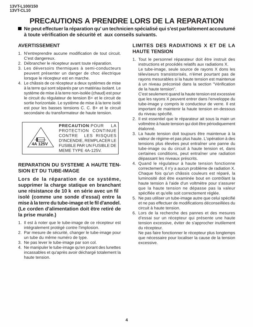
PRECAUTION :POUR LAPROTECTION CONTINUECONTRE LES RISQUESD'INCENDIE, REMPLACER LEFUSIBLE PAR UN FUSIBLE DEMEME TYPE 4A-125V.
4A 125V
LIMITES DES RADIATIONS X ET DE LAHAUTE TENSION
1. Tout le personnel réparateur doit être instruit desinstructions et procédés relatifs aux radiations X.Le tube-image, seule source de rayons X dons lestéleviseurs transistorisés, n'émet pourtant pas derayons mesurables si la haute tension est maintenueà un niveau préconisé dans la section "Vérificationde la haute tension".C'est seulement quand la haute tension est excessiveque les rayons X peuvent entrer dans l'enveloppe dutube-image y compris le conducteur de verre. Il estimportant de maintenir la haute tension en-dessousdu niveau spécifié.
2. Il est essentiel que le réparateur ait sous la main unvoltmètre à haute tension qui doit être périodiquementétalonné.
3. La haute tension doit toujours être maintenue à lavaleur de régime-et pas plus haute. L'opération à destensions plus élevées peut entraîner une panne dutube-image ou du circuit à haute tension et, danscertaines conditions, peut entraîner une radiationdépassant les niveaux préscrits.
4. Quand le régulateur à haute tension fonctionnecorrectement, il n'y a aucun problème de radiation X.Chaque fois qu'un châssis couleurs est réparé, laluminosité doit être examinée bout en contrôlant lahaute tension à l'aide d'un voltmètre pour s'assurerque la haute tension ne dépasse pas la valeurspécifiée et qu'elle soit correctement réglée.
5. Ne pas utiliser un tube-image autre que celui spécifiéet ne pas effectuer de modifications déconseillées ducircuit à haute tension.
6. Lors de la recherche des pannes et des mesuresd'essai sur un récepteur qui présente une hautetension excessive, éviter de s'approcher inutilementdu récepteur.Ne pas faire fonctionner le récepteur plus longtempsque nécessaire pour localiser la cause de la tensionexcessive.
5
13VT-L100/15013VT-CL10
VERIFICATIONS CONTRE L'INCEN-DIE ETLE CHOC ELECTRIQUE
Avant de rendre le récepteur à l'utilisateur, effectuer
123456789012345678901234567890121234567890123456789012345678901212345678901234567890123456789012123412345678901234567890123456789012123456789012345678901234567890121234567890123456789012345678901212341234567890123456789012345678901212345678901234567890123456789012123456789012345678901234567890121234
123456789012345678901234567890121234567890123456789012345678901212345678901234567890123456789012123412345678901234567890123456789012123456789012345678901234567890121234567890123456789012345678901212341234567890123456789012345678901212345678901234567890123456789012123456789012345678901234567890121234
AVIS POUR LA SECURITE
De nombreuses pièces, électriques et mécaniques, dansles téléviseurs présentent des caractéristiques spécialesrelatives à la sécurité, qui ne sont souvent pas évidentesà vue. Le degré de protection ne peut pas êtrenécessairement augmentée en utilisant des pièces deremplacement étalonnées pour haute tension, puissance,etc.Les pièces de remplacement qui présentent cescaractéristiques sont identifiées dans ce manuel; lespièces électriques qui présentent ces particularités sont
PRECAUTIONS A PRENDRE LORS DE LA REPARATION(Suite)
1. Inspecter tous les faisceaux de câbles pour s'assurerque les fils ne soient pas pincés ou qu'un outil ne soitpas placé entre le châssis et les autres piècesmétalliques du récepteur.
2. Inspecter tous les dispositifs de protection comme lesboutons de commande non-métalliques, les isolants,le dos du coffret, les couvercles ou blindages deréglage et de compartiment, les réseaux derésistance-capacité, les isolateurs mécaniques, etc.
3. S'assurer qu'il n'y ait pas de danger d'électrocutionen vérifiant la fuite de courant, de la facon suivante:
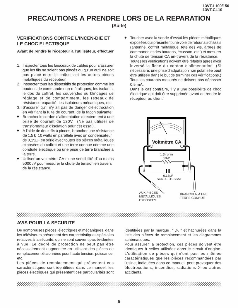
» Brancher le cordon d'alimentation directem-ent à uneprise de courant de 120V. (Ne pas utiliser detransformateur d'isolation pour cet essai).
» A l'aide de deux fils à pinces, brancher une résistancede 1,5 k 10 watts en parallèle avec un condensateurde 0,15µF en série avec toutes les pièces métalliquesexposées du coffret et une terre connue comme uneconduite électrique ou une prise de terre branchée àla terre.
» Utiliser un voltmètre CA d'une sensibilité d'au moins5000 /V pour mesurer la chute de tension en traversde la résistance.
ACVOLTMETER
1.5k ohm10W
0.15µFTEST PROBE
TO EXPOSEDMETAL PARTS
CONNECT TOKNOWN EARTHGROUND
SONDE D'ESSAI
AUX PIECESMETALLIQUESEXPOSEES
Voltmètre CA
BRANCHER A UNETERRE CONNUE
» Toucher avec la sonde d'essai les pièces métalliquesexposées qui présentent une voie de retour au châssis(antenne, coffret métallique, tête des vis, arbres decommande et des boutons, écusson, etc.) et mesurerla chute de tension CA en-travers de la résistance.Toutes les vérifications doivent être refaites après avoirinversé la fiche du cordon d'alimentation. (Sinécessaire, une prise d'adpatation non polarisée peutêtre utilisée dans le but de terminer ces vérifications.)Tous les courants mesurés ne doivent pas dépasser0,5 mA.Dans le cas contraire, il y a une possibilité de chocélectrique qui doit être supprimée avant de rendre lerécepteur au client.
identifiées par la marque " å " et hachurées dans laliste des pièces de remplacement et les diagrammesschématiques.Pour assurer la protection, ces pièces doivent êtreidentiques à celles utilisées dans le circuit d'origine.L'util isation de pièces qui n'ont pas les mêmescaractéristiques que les pièces recommandées parl'usine, indiquées dans ce manuel, peut provoquer desélectrocutions, incendies, radiations X ou autresaccidents.

6
13VT-L100/15013VT-CL10
ELECTRICAL SPECIFICATIONS
TV SECTIONPOWER INPUT: 120 V AC 60 Hz
POWER RATING: 65 WPICTURE SIZE
Width: 37.8 cmHeight: 38.7 cmDepth: 38.2 cm
CONVERGENCE: MagneticSWEEP DEFLECTION: Magnetic
FOCUS: Hi-Bi-Potential ElectrostaticINTERMEDIATE FREQUENCIES
Picture IF Carrier Frequency: 45.75 MHzSound IF Carrier Frequency: 41.25 MHz
Color Sub-Carrier Frequency: 42.17 MHz (Nominal)AUDIO POWER OUTPUT RATING: 0.8 W (at 10% Distortion)
SPEAKERSize: 5 × 9 cm (2" × 31/2")
Voice Coil Impedance: 16 ohm at 400 HzVHF/UHF ANTENNA INPUT IMPEDANCE: 75 ohm unbalanced
TUNING RANGESVHF-Channels: 2 thru 13
UHF -Channels: 14 thru 69CATV Channels: 1,14 thru 125 (EIA, Channel Plan)
VCR SECTIONFormat: VHS Standard
Video Recording System: Rotary Two-Head Helical ScanningNumber of Video Heads: 2 pcs.
Video Signal Standard: NTSC Color SystemTape Width: 12.7mm (1/2inch)
Tape Speed: (SP)33.35mm/sec (1.31 i.p.s)(LP)16.67mm/sec (0.66 i.p.s)Play back only(EP)11.12 mm/sec (0.44 i.p.s)
Maximum Recording Time: (SP)160 min (T-160)(EP)480 min (T-160)
Video Input: 0.5 to 2.0 Vp-p, 75 ohm unbalancedAudio Input: -8 dB, 47k ohm unbalanced (0 dB-0.775 Vrms)
Operating Temperature: 5°C to 40°C (41°F to 104°F)Storage Temperature: -20°C to 60°C (-4°F to 140°F)
Specifications are subject to change without prior notice.

7
13VT-L100/15013VT-CL10
Description Of Controls
LOCATION OF USER'S CONTROL

8
13VT-L100/15013VT-CL10
Location Of Control’s Buttons (Remote Control)
LOCATION OF USER'S CONTROL (Continued)
Remote Control Battery Installation
Before using the television, prepare the Remote Control.
Battery Cover
Pull Up
» Remote the battery cover as shown and insert two batteries (size“AA”) making sure the polarity matches the (+) and (–) marks insidethe battery conpartment.

9
13VT-L100/15013VT-CL10
1. Remove the 7 rear cover fixing screws and detach the rear cover.2. Take out the anode cap, CRT PWB, connectors K and M, coating earth, Speaker chip fixing screws and others.3. Take out the main PWB unit and the VCR unit.4. Remove the 5 VCR fixing screws, and detach the shielding case.
DISASSEMBLY AND REASSEMBLY
3
2
K
M
1
4

10
13VT-L100/15013VT-CL10
5. Remove the 4 cassette housing control fixing screws, and detach the cassette housing control.6. Remove the 2 mechanism chassis angle fixing screws, and remove the 1 head amp shielding case fixing screw.7. Remove the 3 mechanism chassis fixing screws, and detach the mechanism chassis from the main PWB.8. Remove the 2 main PWB fixing screws, and detach the main PWB.9. Remove the 2 power PWB fixing screws, and detach the power PWB
DISASSEMBLY AND REASSEMBLY (Continued)
5
7
7
6
89

11
13VT-L100/15013VT-CL10
DISASSEMBLY AND REASSEMBLY (Continued)
For servicing any of the components inside, disconnect the lead dressing holder. Position the main PWB unit upright asshown below and connect the leads for starting the services.
GC YC
M
KS YC
FRONT
SP
PO
PG
PG
S
GC
PO

12
13VT-L100/15013VT-CL10
INSTALLATION AND SERVICE INSTRUCTIONS
Note: (1) When performing any adjustments to resistor controls and transformers use non-metallicscrewdriver or TV alignment tools.
(2) Before performing adjustment, TV set must be on at least 15 minutes.
CIRCUIT PROTECTIONThe receiver is protected by a 4.0A fuse (F701), mountedon PWB-A, wired into one side of the AC line input.
X-RADIATION PROTECTOR CIRCUITTESTAfter service has been performed on the horizontaldeflection system, high voltage system, or B+ system,test the X-Radiation protector circuit to ascertain properoperation as follows:1. Apply 120V AC using a variac transformer for accurate
input voltage.2. Allow for warm up and using the remote controller,
set the brightness level and contrast level to maximum.3. Check the voltage of test point TP653. (It’s voltage
should be about 10.1V DC.)4. Apply external 13.1V DC at TP653 by using an
external DC supply. The increased voltage will causethe horizontal oscillator to stop and the TV to shut off.
5. To re-start the oscillator, remove the external DCpower supply and short together TP651 and TP652.Once the TV set operates normally again, remove theshort between TP651 and TP652.
HIGH VOLTAGE CHECKHigh voltage is not adjustable but must be checkedto verify that the receiver is operating within safe andefficient design limitations as specified checksshould be as follows:1. Connect an accurate high voltage meter between
ground and anode of Picture tube.2. Operate receiver for at least 15 minutes at 120V AC
line voltage, with strong air signal or properly tuned intest signal.
3. Set to Service mode on, "Mute" and bus data 1(Y-mute on).
4. The voltage should be approximately 25.4kV (at zerobeam). If a correct reading cannot be obtained, checkcircuitry for malfunctioning components.After the voltage test, "Mute" and bus data "0" (Y-muteoff).

13
13VT-L100/15013VT-CL10
1. Service modeBerfore putting unit into the service mode, check, thatcustomer adjustments are in the normal mode, usethe reset function in the video adjust menu to ensurecustomer controls are in their proper (reset) position.
To enter the service modePlug in a television set, during push S2507 (CH-up).When successfuly entered, the service mode will bedisplayed as shown in Figure A .
To exit service modeTurn off the power or unplug the set.
2. Adjustment Item selectionOnce in the service mode, press the channel up orchannel down button on the remote controller or atthe set (Table-A.). Select the item you wish to adjust.
PICTURE: 16 2
The L-series SHARP TV/VCR COMBINATION have most of the analog setup adjustments eliminated. Coil andvariable resistor adjustments are now performed digitally by using the remote transmitter or set’s volume andchannel change function buttons.Note: There are still a few analog adjustments in the L-series such as 120V adjust, focus, master screen voltage
and coils in the picture IF/detector circuit.Follow the steps below whenever service adjustment is required. See table "B" to determine if serviceadjustments are required.
3. Data number selectionPress the volume up or down button to adjust the datanumber in the upper right hand side of the screen.
Figure A.

14
13VT-L100/15013VT-CL10
Table - B
*No adjustment is required due to proper setting being made by IC2001 automatically.
Table - A
ADJUSTMENTITEM
DATAINTIAL VALUE RANGE
ADJUSTMENTCOMMENTS
PICTURE 16 0~63TINT 39 0~77COLOR 13 0~63BRIGHT 32 0~63SHARPNESS 7 0~13VERTICAL PHASE 0 0~7H-PHASE 20 0~31RF-AGC 18 0~63V-AMP 32 0-63PIF-VCO 40 0-127R CUT-OFF 0 0~255G CUT -OFF 0 0~255B CUT-OFF 0 0~255G GAIN 128 0-255B GAIN 128 0-255Y-MUTE 0 0-2 "0"= Normal raster "1"= no"Y"
"2"= No VerticalBALANCE 32 0~63TEXT BOX 15 0-127TEXT PICTURE 20 0-80CCD LEVEL 7 0-10OPTION 1 0-3
PARTREPLACED
ADJUSTMENTNECESSARY UNNECESSARY
NOTE
IC2001 X
IC401 X
IC2101 X
CRT X
Data is stored in IC2101.
The adjustment is needed to compensate for characteristicsof parts including IC401.
Initial setting values are written from IC2001. Adjust for bestresults.
Adjust items related to picture tube only.

15
13VT-L100/15013VT-CL10
White Balance Adjustment1. Have unit receive a good local channel.2. Enter the service mode. Select service adjustment
item "COLOR" and set to "0" (minimum color)."COLOR" does not have to be adjusted if you selecteda B/W picture or monoscope pattern.
3. Alternately adjust service adjustment data of "G GAIN"and "B GAIN" untill a good grey scale with normalwhites is obtained.
4. Select service adjustment item "COLOR" and adjustdata to obtain normal color level.
Picture Adjustment1. Have unit receive a good local channel.2. Make sure the customer picture control is set to
maximum.3. Enter the service mode and select service adjustment
item "PICTURE".4. Adjust the data value to achieve normal contrast
range.
Tint Adjustment1. Have unit receive a good local channel.2. Set customer tint control to center of it’s range.3. Enter the service mode and select service adjustment
item "TINT".4. Adjust "TINT" data value to obtain normal flesh tones.
Color Adjustment1. Have unit receive a good local channel.2. Make sure the customer color control is set to center
position .3. Enter the service mode and select service adjustment
item "COLOR".4. Adjust "COLOR" data value to obtain normal color
level.
Brightness Adjustment1. Have unit receive a good local channel.2. Make sure the customer brightness control is set to
center position.3. Enter the service mode and select service adjustment
item "BRIGHT".4. Adjust "BRIGHT" data value to obtain normal
brightness level.
SERVICE ADJUSTMENT
VCO Adjustment1. Connect a digital voltmeter between pin (44) of IC401
and ground.2. Select a good local channel.3. Enter the service mode. select adjustment item PIF-
VCO and data value "40".4. Adjust the VCO coil L202 so that the digital voltmeter
reads 2.5 volts.5. Adjustment is complete, remove the voltmeter, return
to "normal" mode.
RF AGC Adjustment1. Have unit receive a good local channel.2. Enter the service mode and select service adjustment
item "RF-AGC".3. Set the data value to point where no noise or beat
appears.4. Select another channel to confirm that no noise or
beat appears.Note 1: You will have to come out of the service mode
to select another channel.Note 2: Setting the data to "0" will produce a black
raster.
Screen Adjustment1. Select a good local channel.2. Enter the service mode and select service adjustment
item "COLOR" and set the data value to "0" to set thecolor level to minimum. You may skip this step, if youselected a B/W picture or monoscope pattern.
3. Select service adjustment item "Y-MUTE" and adjustthe data value to "1", this turns off the luminance signal(Y-mute).
4. Select service adjustment item "BRIGHT" and set thevalue to "32".
5. Adjust the master screen cotrol untill raster darkensto the point where raster is barely seen.
6. Adjust service adjustments item "R-CUT OFF" red "G-CUT OFF" green and "B-CUT OFF" blue to obtain agood grey scale with normal whites at low brightnesslevel.
7. Select service adjustment item "MUTE" and reset datato "0". Select service adjustment item "COLOR" andreset data to obtain normal color level.

16
13VT-L100/15013VT-CL10
Figure B.
Vertical-Size adjustment1. Have unit receive a good local channel.2. Enter the service mode and select service adjustment
item "V-AMP".3. While observing the top and bottom of the screen,
adjust "V-AMP" data value to proper vertical size andlinearity.
Horizontal Position Adjustment1. Have unit receive a good local channel.2. Enter the service mode and select service adjustment
item "H-PHASE".3. Adjust "H-PHASE" data value so that picture is
centered.
Caption Position Adjustment(Horizontal)1. Have unit receive a good local channel.2. Enter the service mode and select service adjustment
item "TEXT BOX".3. A black text box appears on the screen. (See Figure
B. below.)4. Adjust "TEXT BOX" data value so that text box is
positioned in the center of the screen.

13VT-L100/15013VT-CL10
17
PRECAUTIONS IN REASSEMBLING
MOUTING THE CASSETTE CONTROLLERInitial setting is indispensable before placing the cassette controller in the mechanism. The initial setting is made in two ways;electricaland mechanical.
Electrical setting:Make a short-circuit between TP7701 and TP7702 and be sure that the mechanism is back to its initial setting position (*1).
COUPLING THE MECHANISM TO THE PWBMatch the mechanism’s projections with the two symbols (round reference and oval sub-reference) on the main PWB. Place themechanism straight down in position with due care so that the mechanism chassis’s outer edges should not damage any parts nearby.Tighten up the two screws (one for fixing the mechanism and the head amplifier shield, the other on the main PWB’s soldering sideand located near the loading motor) to fix the mechanism and main PWB. Reconnect the FFC cables (MH and AA, ME and AD, DrumUnit and AH) between the mechanism and main PWB.Parts to pay attention to:
Start and end sensors Q7703, Q7704Record tip switch S7701
Take special care of the connectors (board to board; AC, AE, AL) between the mechanism and main PWB.
Mechanical setting:Turn the loading motor’s pulley feed gear using ascrewdriver and be sure that the mechanism is backto its initial setting position (*1). Now place thecassette controller in position.(This method is appli-cable for the mechanism alone.)
Pulley feed gear
Screwdriver
Large tooth
Casecondrive gear
Drive angle ofcassette control
END SENSOR
REC TIP SW
AL Connector
AE Connector
AC Connector
START SENSOR

13VT-L100/15013VT-CL10
18
FUNCTION OF MAJOR MECHANICAL PARTS (TOP VIEW)
No. Function No. Function
1. Full erase head ass’yErase the old recording on the tape in the record-ing mode.
3. Tension arm ass’yDetects the tension of tape while running, andbrakes the supply reel disk via the tension band.
7. Sup Main brake leverBrakes the supply reel disk to prevent tapeslackening when the unit is stopped in fast for-ward or rewind mode.
9. Main take-up brake leverBrakes the take-up reel disk to prevent tapeslackening when the unit is stopped in fast for-ward or rewind mode.
13. Reverse guide lever ass’yPulls out the tape and controls the tape drive trainheight with the upper and lower guides.
16. Pinch roller lever ass’yPress-fits the tape to the capstan during taperunning.
18. Loading motorA motive power which drives the mechanism. Ittransmits the power to the master cam and cas-sette housing control ass'y.
Full EraseHead
Supply PoleBase Ass'y
Supply ReelDisk
Sup MainBrake Ass'y
Idler WheelAss'y
Take-upReel Disk
LoadingMotor
TensionArm Ass'y
Fixing Guide2211
20
21
19
17
16
10
13
8
14
9
181586
3
7
2
1
Drum Ass'y
Drum Motor
Take-up Pole Base Ass'y
A/C Head Ass'y
Pinch RollerLever Ass'y
Automatic Head Cleaner Ass'y
Pinch Drive Cam
Pinch Drive Lever Ass'y
Casecon Drive Gear
Tu Main Brake Ass'y
Reverse Guide Lever Ass'y

13VT-L100/15013VT-CL10
19
FUNCTION OF MAJOR MECHANICAL PARTS (BOTTOM VIEW)
Capstan D. D. Motor
Drive Belt
Slow Brake
Master Cam
Casecon Drive Gear
Clutch Lever
Limiter Pulley Ass'y
Shifter
3
4
1
2
7
5 6
8
No. FunctionNo. Function
6. Limiter pulley ass’yTransmits the power of the capstan D.D. motor tothe reel disk via the drive idler.
8. ShifterTransmits the operation of the master cam to breakass’y, Ioading gear, tension arm and clutch lever.
9. Take-up loading gearShifts the take-up pole base and guide roller via theloading gear T, and applies the tape around the drumassembly, as well as transmits the power to theloading gears.
1. Slow brakeGets in contact with the capstan D.D. motorlinking to the master cam in the slow still mode,and brakes it to a certain degree.
3. Capstan D.D. motorA motive power which runs the tape. It transmitsthe power via the Drive belt.
4. Drive beltTransmits the power to run the tape to the Limiterpulley.
13VT-L100/15013VT-CL10
20
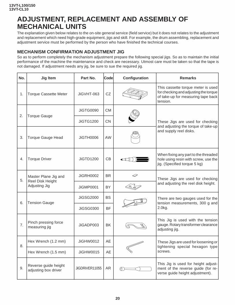
ADJUSTMENT, REPLACEMENT AND ASSEMBLY OFMECHANICAL UNITSThe explanation given below relates to the on-site general service (field service) but it does not relates to the adjustmentand replacement which need high-grade equipment, jigs and skill. For example, the drum assembling, replacement andadjustment service must be performed by the person who have finished the technical courses.
MECHANISM CONFIRMATION ADJUSTMENT JIGSo as to perform completely the mechanism adjustment prepare the following special jigs. So as to maintain the initialperformance of the machine the maintenance and check are necessary. Utmost care must be taken so that the tape isnot damaged. If adjustment needs any jig, be sure to sue the required jig.
1. Torque Cassette Meter JiGVHT-063 CZ
JiGTG1200 CN
JiGMP0001 BY
No. Jig ltem Part No. Code Configuration Remarks
JiGTG0090 CM
3. Torque Gauge Head JiGTH0006 AW
5.JiGRH0002 BR
JiGSG2000 BS
JiGSG0300 BF
6.
7. JiGADP003 BK
8.
9. JiGDRiVER11055 AR
2. Torque Gauge
Tension Gauge
These Jigs are used for checkingand adjusting the reel disk height.
When fixing any part to the threadedhole using resin with screw, use thejig. (Specified torque 5 kg)
This cassette torque meter is usedfor checking and adjusting the torqueof take-up for measuring tape backtension.
These Jigs are used for checkingand adjusting the torque of take-upand supply reel disks.
Master Plane Jig andReel Disk HeightAdjusting Jig
Pinch pressing forcemeasuring jig
Reverse guide heightadjusting box driver
This Jig is used for height adjust-ment of the reverse guide (for re-verse guide height adjustment).
Hex Wrench (1.5 mm) JiGHW0015 AE
This Jig is used with the tensiongauge. Rotary transformer clearanceadjusting jig.
There are two gauges used for thetension measurements, 300 g and2.0kg.
Hex Wrench (1.2 mm) JiGHW0012 AE
4. Torque Driver JiGTD1200 CB
These Jigs are used for loosening ortightening special hexagon typescrews.

13VT-L100/15013VT-CL10
21
12. JiGDRiVER-6 BM
11. JiGDRiVERH-4 AP
No. Jig ltem Part No. Code Configuration Remarks
This screwdriver is used for adjust-ing the guide roller height.
VROATSV CD
These tapes are especially used forelectrical fine adjustment.
VROBBZGS CB 7k — 30µm
This Jig is used for heightadjustment of the reverse guide.
Guide roller heightadjustment drive
10. Alignment Tape
X value adjustmentgear type screw driver
Reverse Guide HeightAdjusting Jig
525 Monoscope
Video Audio Hi-Fi Audio Track
525 Monoscope 7k — 58µm
NTSC Color Bar 1k — 58µm
13. JiGRVGH-F18 BU
For X value adjustment

13VT-L100/15013VT-CL10
22
MAINTENANCE CHECK ITEMS AND EXECUTION TIME
Perform the maintenance with the regular intervals as follows so as to maintain the quality of machine.
PartsMaintained 500
hrs.1000hrs.
1500hrs.
2000hrs.
Guide roller ass’y
Sup Guide Shaft
Retaining guide
Slant pole
Full-erase head Colour and beating
Clean tape contact part withthe specified cleaning liquid.
Abnormal rotation or significant vi-bration requires replacement.
RemarksPossible symptomencountered
3000hrs.
Lateral noises Headoccasionally blocked
Small sound or sounddistortion
Upper and lower drum ass’yPoor S/N ratio, no colorPoor flatness of the enve-lope with alignment tape
Clean rubber and rubbercontact area with thespecified cleaning liquid.
Pinch rollerNo tape running, tapeslack
No tape running, tapeslack, no fast forward/rewind motion
Reel belt
Cassette not loaded orunloaded
Idler ass’y
Tension band ass’y Screen swaying
Loading Motor
Limiter pulley
Supply/take-up Main brake levers Tape slack
A/C head
No tape running, tapeslack
NOTE: : Part replacement. : Cleaning : Oil refilling<Specified> Cleaning liquid Industrial ethyl alcohol
* This mechanism does not need electric adjustment with variable resistor. Check parts. If any deviation is found, cleanor replace parts.
Clean tape contact area withthe specified cleaning liquid.
Capstan D.D. MotorNo tape running, unevencolor

13VT-L100/15013VT-CL10
23
Figure 1-1.
• Reassembly1. Before installing the cassette housing control, short-
circuit TP7701 and TP7702 provided at the left of themain PWB, prug in the power cord. The casecon drivegear turns and stops when the positioning mark ap-pears. Engage two teeth of casecon drive gear with thethree teeth of casecon drive angle gear, and set on themechanism chassis as shown below.
Figure 1-2.
2. Install in the reverse order of removal.
REMOVING AND INSTALLING THE CASSETTEHOUSING• Removal1. In the cassette eject mode, remove the cassette.2. Unplug the power cord.3. Remove in the following numerical order.
a) Remove two screws 1.b) Slide and pull up the cassette housing control.
Figure 1-3.
Notes:1. When fitting the S/E sensor holder to the cassette
controller frame L/R, take care.2. Misengagement of teeth of casecon drive gear and drive
angle gear causes malfunction. (The cassette cannot beset, load and ejection are repeated).
3. In the case when you use the magnet screw driver, neverapproach the magnet driver to the A/C head, FE head,and drum.
4. When installing or removing, take care so that thecassette housing control and tool do not contact theguide pin or drum.
5. After installing the cassette housing control once per-form cassette loading operation.
TO RUN A TAPE WITHOUT THE CASSETTEHOUSING CONTROL ASSEMBLY1. Short-circuit TP7701 and TP7702.2. Plug in the power cord.3. Turn on the power.4. Open the lid of a cassette tape by hand.5. Hold the lid with two pieces of vinyl tape.6. Set the cassette tape in the mechanism chassis.7. Stabilize the cassette tape with a weight (500g) to
prevent floating.8. Perform running test.
Notes:1. The weight should not be more than 500g.2. Take care not to damage the tape when the Cassette is
set in the mechanism shassis or taken out of it becausethe supply/take-up poles are shifted foward the tapeloading direction in the EJECT position.
1
Mechanism chassisWeight to preventfloat (500g)
500g
Casecondrive gear
Casecon driveangle gear
13VT-L100/15013VT-CL10
24
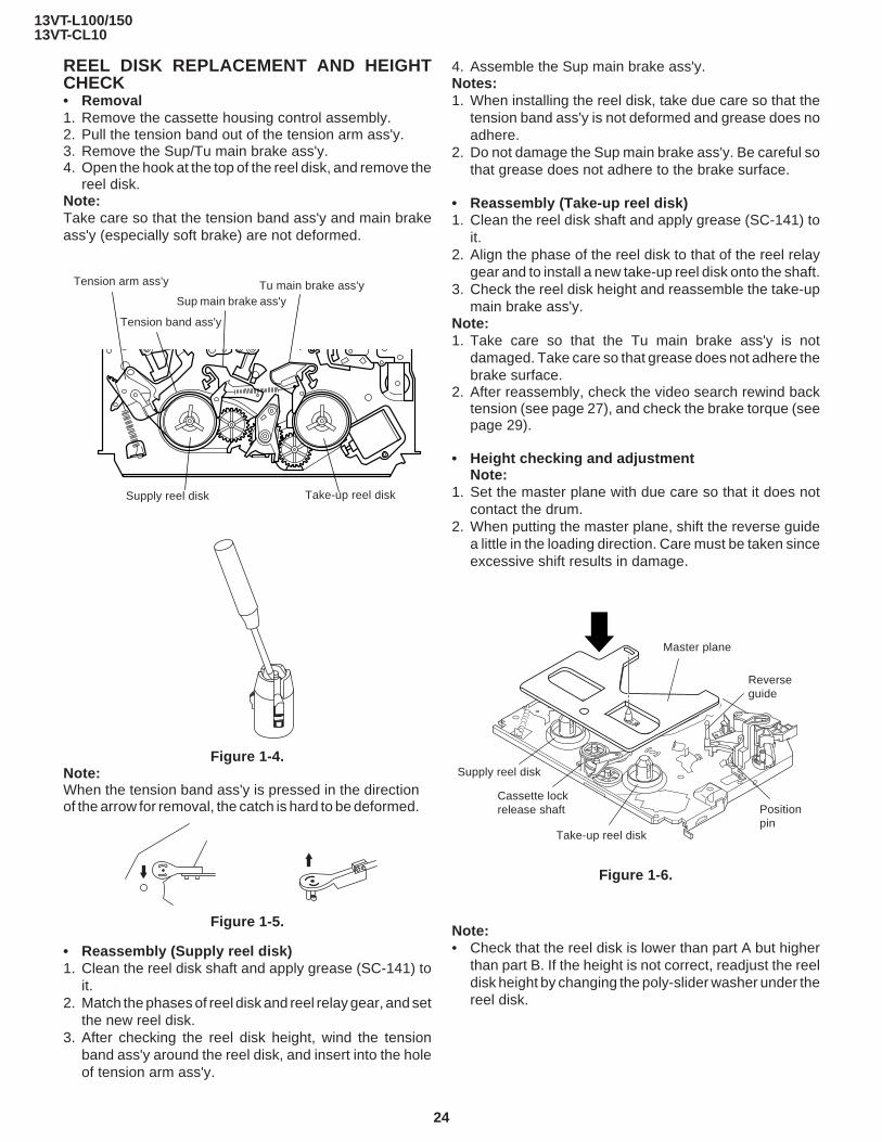
REEL DISK REPLACEMENT AND HEIGHTCHECK• Removal1. Remove the cassette housing control assembly.2. Pull the tension band out of the tension arm ass'y.3. Remove the Sup/Tu main brake ass'y.4. Open the hook at the top of the reel disk, and remove the
reel disk.Note:Take care so that the tension band ass'y and main brakeass'y (especially soft brake) are not deformed.
Note:When the tension band ass'y is pressed in the directionof the arrow for removal, the catch is hard to be deformed.
Figure 1-5.
• Reassembly (Supply reel disk)1. Clean the reel disk shaft and apply grease (SC-141) to
it.2. Match the phases of reel disk and reel relay gear, and set
the new reel disk.3. After checking the reel disk height, wind the tension
band ass'y around the reel disk, and insert into the holeof tension arm ass'y.
4. Assemble the Sup main brake ass'y.Notes:1. When installing the reel disk, take due care so that the
tension band ass'y is not deformed and grease does noadhere.
2. Do not damage the Sup main brake ass'y. Be careful sothat grease does not adhere to the brake surface.
• Reassembly (Take-up reel disk)1. Clean the reel disk shaft and apply grease (SC-141) to
it.2. Align the phase of the reel disk to that of the reel relay
gear and to install a new take-up reel disk onto the shaft.3. Check the reel disk height and reassemble the take-up
main brake ass'y.Note:1. Take care so that the Tu main brake ass'y is not
damaged. Take care so that grease does not adhere thebrake surface.
2. After reassembly, check the video search rewind backtension (see page 27), and check the brake torque (seepage 29).
• Height checking and adjustmentNote:
1. Set the master plane with due care so that it does notcontact the drum.
2. When putting the master plane, shift the reverse guidea little in the loading direction. Care must be taken sinceexcessive shift results in damage.
Figure 1-4.
Tension arm ass'y
Supply reel disk Take-up reel disk
Sup main brake ass'yTu main brake ass'y
Tension band ass'y
Master plane
Reverseguide
Positionpin
Supply reel disk
Cassette lockrelease shaft
Take-up reel disk
Figure 1-6.
Note:• Check that the reel disk is lower than part A but higher
than part B. If the height is not correct, readjust the reeldisk height by changing the poly-slider washer under thereel disk.

13VT-L100/15013VT-CL10
25
Note:Whenever replacing the reel disk, perform the height check-ing and adjustment.
A B
Figure 1-7.
Master planeReel disk heightadjusting jig
Mechanism chassis
Reel disk
10 ± 0.2mm Reel disk
CHECKING AND ADJUSTMENT OF TAKE-UPTORQUE IN FAST FORWARD MODE• Remove the cassette housing control assembly.
• After short-circuiting TP7701 and TP7702 providedat the left on the main PWB, plug in the power cord,then turn on the power.
• Setting1. Set a torque gauge to zero on the scale. Place it on the
take-up reel disk.2. Press the FF button.3. To calculate the remaining capacity of the play back
mode, slowly rotate the supply reel disk, and then shiftit into the forward mode.
• Checking1. Turn the torque gauge slowly (one rotation every 2 to 3
seconds) by hand in the CW direction.2. Make sure that the indication of torque gauge is not less
than 30mN·m (306gf·cm).
Torque gauge
30mN·m (306gf·cm)or more
Supply reel disk
Idler ass'y
The gauge is held atits maximum value.(Red mark)
CCW
Figure 1-9.
• Adjustment1. If the FF winding-up torque is less than the specified
value, clean the capstan D.D. motor pulley, drive belt,and limiter pulley with cleaning liquid, and check again.
2. If the torque is less that the set value, replace the reelbelt.
Notes:1. Hold the torque gauge by hand so that it is not moved.2. Do not keep the reel disk in lock state. Do not allow long-
time measurement.
CHECKING AND ADJUSTMENT OF TAKE-UPTORQUE IN REWIND MODE• Remove the cassette housing control assembly.
• After short-circuiting TP7701 and TP7702 providedat the left on the main PWB, plug in the power cord,then turn on the power.
• Setting1. Set a torque gauge to zero on the scale. Place it on the
supply reel disk.2. Press the rewind button.3. To calculate the remaining capacity, slowly rotate the
take-up reel disk, and then shift it into the rewind mode.
• Checking1. Turn the torque gauge slowly (one rotation every 2 to 3
seconds) by hand in the CCW direction.2. Make sure that the indication of torque gauge is not less
than 30mN·m (306gf·cm).
Figure 1-8.
Torque gauge
30mN·m (306gf·cm)or more
The gauge is held atits maximum value.(Red mark)
Idler ass'y
CW
• Adjustment1. If the rewind winding-up torque is less than the specified
value, clean the capstan D.D. motor pulley, drive belt,and limiter pulley with cleaning liquid, rewind again, andcheck the winding-up torque.
2. If the winding-up torque is still out of range, replace thedrive belt.
13VT-L100/15013VT-CL10
26
Figure 1-10.
Notes:1. Hold the torque gauge by hand so that it is not moved.2. Do not keep the reel disk in lock state. Do not allow long-
time measurement.
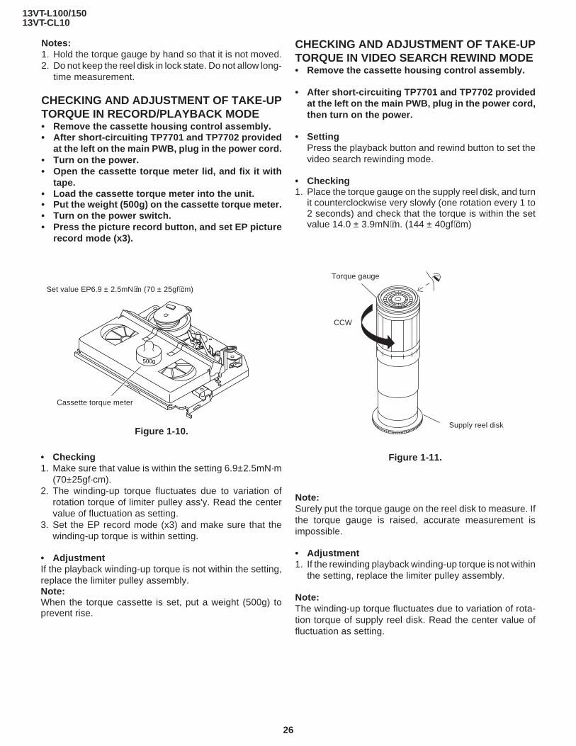
CHECKING AND ADJUSTMENT OF TAKE-UPTORQUE IN RECORD/PLAYBACK MODE• Remove the cassette housing control assembly.• After short-circuiting TP7701 and TP7702 provided
at the left on the main PWB, plug in the power cord.• Turn on the power.• Open the cassette torque meter lid, and fix it with
tape.• Load the cassette torque meter into the unit.• Put the weight (500g) on the cassette torque meter.• Turn on the power switch.• Press the picture record button, and set EP picture
record mode (x3).
CHECKING AND ADJUSTMENT OF TAKE-UPTORQUE IN VIDEO SEARCH REWIND MODE• Remove the cassette housing control assembly.
• After short-circuiting TP7701 and TP7702 providedat the left on the main PWB, plug in the power cord,then turn on the power.
• SettingPress the playback button and rewind button to set thevideo search rewinding mode.
• Checking1. Place the torque gauge on the supply reel disk, and turn
it counterclockwise very slowly (one rotation every 1 to2 seconds) and check that the torque is within the setvalue 14.0 ± 3.9mN⋅m. (144 ± 40gf⋅cm)
Set value EP6.9 ± 2.5mN⋅m (70 ± 25gf⋅cm)
500g
Cassette torque meter
Torque gauge
Supply reel disk
CCW
Figure 1-11.
Note:Surely put the torque gauge on the reel disk to measure. Ifthe torque gauge is raised, accurate measurement isimpossible.
• Adjustment1. If the rewinding playback winding-up torque is not within
the setting, replace the limiter pulley assembly.
Note:The winding-up torque fluctuates due to variation of rota-tion torque of supply reel disk. Read the center value offluctuation as setting.
• Checking1. Make sure that value is within the setting 6.9±2.5mN·m
(70±25gf·cm).2. The winding-up torque fluctuates due to variation of
rotation torque of limiter pulley ass'y. Read the centervalue of fluctuation as setting.
3. Set the EP record mode (x3) and make sure that thewinding-up torque is within setting.
• AdjustmentIf the playback winding-up torque is not within the setting,replace the limiter pulley assembly.Note:When the torque cassette is set, put a weight (500g) toprevent rise.

13VT-L100/15013VT-CL10
27
CHECKING THE VIDEO SEARCH REWINDBACK TENSION• Remove the cassette housing control assembly.
• After short-circuiting TP7701 and TP7702 providedat the left on the main PWB, plug in the power cord,then turn on the power.
• Checking1. After pressing the play button, press the rewind button,
and set the video search rewind mode.2. Place the torque gauge on the take-up reel disk, and turn
it counterclockwise very slowly (one rotation every 2 to3 seconds) and check that the torque is within the setvalue 3.4±1.5mN⋅m (35±15gf⋅cm).
Figure 1-13.
Torque gauge
Take-up reel disk
CCW
Figure 1-12.
Notes:Set the torque gauge securely on the take-up reel disk.If it is not secure, the measurement will be incorrect.
CHECKING THE PINCH ROLLER PRESSURE• Remove the cassette housing control assembly.
• After short-circuiting TP7701 and TP7702 providedat the left on the main PWB, plug in the power cord,then turn on the power.
• CheckingPress the play button to set the playback mode.
Pinch roller Tension gauge900 - 1,200g
Capstan shaft
Tension gauge adapter
1. Detach the pinch roller from the capstan shaft.Do not separate excessively. Or the pinch lever andpinch double action lever may disengage.
2. Engage the tension gauge adapter with the pinch rollershaft, and pull in the arrow direction.
3. Gradually return the pinch roller, and measure thepulling force when the pinch roller contacts the capstanshaft.
4. Make sure that the measured value is within setting 0.9to 11.8 N (900 to 1,200g).
CHECKING AND ADJUSTMENT OF TENSIONPOLE POSITION• Remove the cassette housing control assembly.
• After short-circuiting TP7701 and TP7702 providedat the left on the main PWB, plug in the power cord,then turn on the power.
• Setting1. Open the cassette tape (T-120), and fix with tape.2. Set the cassette tape in loading state.3. Put the weight (500g) on the cassette tape.4. Make the adjustment with the beginning of a T-120 tape.
• Checking1. Set a cassette tape, push the REC button to place the
unit in the SP record mode. Now check the tension poleposition.
(T-120)
Weight to preventfloat (500g)
500g
Figure 1-14.
13VT-L100/15013VT-CL10
28
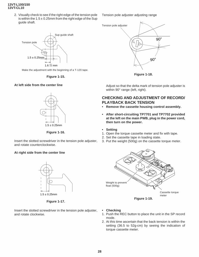
2. Visually check to see if the right edge of the tension poleis within the 1.5 ± 0.25mm from the right edge of the Supguide shaft.
Insert the slotted screwdriver in the tension pole adjuster,and rotate clockwise.
Figure 1-17.
At left side from the center line
Figure 1-15.
Figure 1-16.
Insert the slotted screwdriver in the tension pole adjuster,and rotate counterclockwise.
At right side from the center line
1.6 mm-0.1-0.6
1.5 ± 0.25mm
1.5 ± 0.25mm
1.5 ± 0.25mm
Sup guide shaft
Make the adjustment with the beginning of a T-120 tape.
Tension pole adjuster
90°
90°
Tension pole
500g
Weight to preventfloat (500g)
Cassette torquemeter
Tension pole adjuster adjusting range
Adjust so that the delta mark of tension pole adjuster iswithin 90° range (left, right).
CHECKING AND ADJUSTMENT OF RECORD/PLAYBACK BACK TENSION• Remove the cassette housing control assembly.
• After short-circuiting TP7701 and TP7702 providedat the left on the main PWB, plug in the power cord,then turn on the power.
• Setting1. Open the torque cassette meter and fix with tape.2. Set the cassette tape in loading state.3. Put the weight (500g) on the cassette torque meter.
• Checking1. Push the REC button to place the unit in the SP record
mode.2. At this time ascertain that the back tension is within the
setting (36.5 to 52g·cm) by seeing the indication oftorque cassette meter.
Figure 1-18.
Figure 1-19.

13VT-L100/15013VT-CL10
29
• Adjustment1. If the indication of torque cassette meter is lower than
the setting, shift the tension spring engagement to thepart A.
2. If the indication of torque cassette meter is higher thanthe setting, shift the tension spring engagement to thepart B.
CCW: 8.8~23.5mN⋅m (90~240gf⋅cm)
CW: 4.9~11.8mN⋅m (50~120gf⋅cm)
Figure 1-20.
CHECKING THE BRAKE TORQUE• Checking the brake torque at the supply side
CCW: 3.9~9.8mN⋅m (40~100gf⋅cm)
CW: 8.8~23.5mN⋅m (90~240gf⋅cm)
Figure 1-21.• Remove the cassette housing control assembly.
• After short-circuiting TP7701 and TP7702 providedat the left on the main PWB, plug in the power cord,then turn on the power.
• Setting1. Set a torque gauge to zero on the scale. Place it on the
supply reel disk.2. Switch from the FF mode to the STOP mode.3. Disconnect the power cord.
• CheckingTurn the torque gauge at a rate of about one turn/2 secin the CW direction/CCW direction with respect to thesupply reel disk so that the reel disk and torque gaugepointer rotate at equal speed, and make sure that thevalue is within the setting (CW direction: 8.8 to 23.5mN·m(90 to 240gf·cm); CCW direction: 3.9 to 9.8mN·m (40 to100gf·cm).
Tension arm
Tension spring
CW
CCW CW
Supply reel disk
Torque gauge
Torque gauge
CCW
Take-up reeldisk
A B
• Checking the brake torque at the take-up side
• Remove the cassette housing control assembly.
• After short-circuiting TP7701 and TP7702 pro-vided at the left on the main PWB, plug in thepower cord, then turn on the power.
• Setting1. Switch from the FF mode to the STOP mode.2. Disconnect the power cord.3. Set a torque gauge to zero on the scale. Place it on the
take-up reel disk.
• Checking1. Turn the torque gauge at a rate of about one turn/2 sec
in the CCW direction/CW direction so that the reel diskand torque gauge pointer rotates at equal speed andmake sure that the value is within the setting (CCWdirection: 8.8 to 23.5mN·m (90 to 240gf·cm), CWdirection: 4.9 to 11.8 mN·m (50 to 120gf·cm).
2. Adjustment of the brake torque at the supply side andthe take-up side
• Unless the supply side brake torque or take-up sidebrake torque is within the setting, clean the felt surfaceof reel disk (supply, take-up) brake lever, check againthe brake torque.
• If value cannot be set within the setting yet, replace themain brake ass'y or main brake spring.
Figure 1-22.
13VT-L100/15013VT-CL10
30
REPLACEMENT OF A/C (Audio/Control) HEAD1. Remove the cassette housing control assembly.2. In unloading state, unplug the power cord.
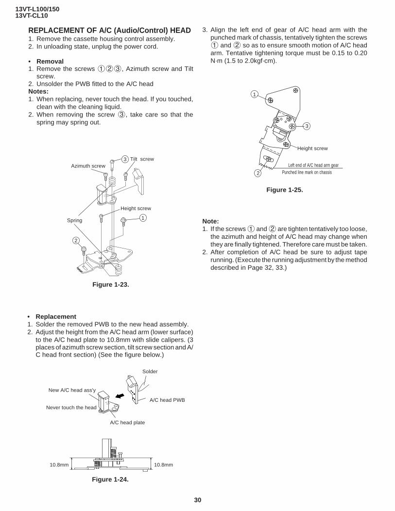
• Removal1. Remove the screws 123, Azimuth screw and Tilt
screw.2. Unsolder the PWB fitted to the A/C headNotes:1. When replacing, never touch the head. If you touched,
clean with the cleaning liquid.2. When removing the screw 3, take care so that the
spring may spring out.
A/C head PWB
Figure 1-24.
Solder
Never touch the head
10.8mm10.8mm
A/C head plate
Figure 1-23.
• Replacement1. Solder the removed PWB to the new head assembly.2. Adjust the height from the A/C head arm (lower surface)
to the A/C head plate to 10.8mm with slide calipers. (3places of azimuth screw section, tilt screw section and A/C head front section) (See the figure below.)
New A/C head ass'y
3. Align the left end of gear of A/C head arm with thepunched mark of chassis, tentatively tighten the screws1 and 2 so as to ensure smooth motion of A/C headarm. Tentative tightening torque must be 0.15 to 0.20N·m (1.5 to 2.0kgf·cm).
Note:1. If the screws 1 and 2 are tighten tentatively too loose,
the azimuth and height of A/C head may change whenthey are finally tightened. Therefore care must be taken.
2. After completion of A/C head be sure to adjust taperunning. (Execute the running adjustment by the methoddescribed in Page 32, 33.)
Figure 1-25.
Punched line mark on chassisLeft end of A/C head arm gear
1
2
3
Height screw
2
Spring 1
Azimuth screw
Height screw
Tilt screw3

13VT-L100/15013VT-CL10
31
500g
Figure 1-27.
Height screw
Azimuth screw
Tilt screw
Cassette tape
Weight to preventfloat (500g)
Mechanism chassis
Tape
0.3mm
A/C head
• AdjustmentAdjust the height screw visually so that the control head isvisible 0.3mm below the bottom of the tape.
Figure 1-29.
Figure 1-28.
A/C HEAD HEIGHT ROUGH ADJUSTMENT
• Setting1. Set the cassette tape in the unit.2. Press the PLAY button to put the unit in the playback
mode.3. Roughly adjust the height of the A/C head by turning the
height screw until the tape is in the position shownbelow.
Figure 1-26.
HEIGHT ADJUSTMENT OF REVERSE GUIDE
1. Adjust the height from the mechanism chassis to thereverse guide lower flange to 13.38 mm, using thereverse guide height adjustment jig, in tape loadingstate. (Refer to Figure 1-28 (a) (b).)
(a) (b)
13.38mm
Reverse guide heightadjusting jigReverse guide height
adjusting jig
Reverse guide
Mechanismchassis
2. Rotate counterclockwise the reverse guide height ad-justment nut 1/10 turn. (For height adjustment use thereverse guide height adjustment box driver (JiGDRiVER11055)).
Box driver
Height adjusting nut
CCW
3. Set the tape, and check for tape crease near the reverseguide in the playback mode.If crease is found, turn the reverse guide adjustment nutto remove crease. (As for crease check refer to Figure 1-30.)
An example ofcrease near thereverse guide
500g
Capstanmotor shaft
Mechanismchassis
Reverse guide
Weight toprevent float (500g)
Fixingguide
A
* Check for crease from the A direction.
Figure 1-30.

13VT-L100/15013VT-CL10
32
ADJUSTMENT OF TAPE DRIVE TRAIN1. Tape run rough adjustment
1 Remove the cassette housing control assembly.2 After shortcircuiting TP7701 and TP7702 provided
at the main PWB, plug in the power cord, then turn onthe power.
3 Check and adjust the position of the tension pole.(See page 28.)
4 Check and adjust the video search rewind backtension. (See page 27.)
5 Connect the oscilloscope to the test point for PBCHROMA envelope output (TP3301). Set the syn-chronism of the oscilloscope to EXT. The PBCHROMA signal is to be triggered by the headswitching pulse (TP3302).
6 Set the alignment tape (VROBBZGS) to play. (Put a500g weight on the cassette tape to prevent lift ofcassette tape.)
500g
Figure 1-31.
7 Press the tracking button (+), (–) and change theenvelope waveform from max to min and from min tomax. At this time make sure that the envelopewaveform changes nearly parallel.
8 Unless the envelope waveform changes nearly par-allel, adjust the height of supply side and take-upside guide roller so that the envelope waveformchanges nearly parallel. (For envelope adjustmentprocedure refer to Figure 1-35.)
9 Turn the tilt screw to remove the tape crease at thefixing guide flange.Play back the tape and check for tape crease at thefixing guide flange.(1) If there is no tape crease
Turn the tilt screw clockwise so that tape creaseappears once at the flange, and then return the tiltscrew so that the crease disappears.
(2) If there is tape creaseTurn counterclockwise the tilt screw so that thetape crease disappears.(Reference) If the tilt screw is turned clockwisecrease appears at the lower flange.
Guide roller
Weight of 500g
Cassette Tape
For X value adjustmentAdjust the X value, turning the gear-type screwdriver.
Notes:1. Previously set the tracking control in the center position,
and adjust the envelope waveform to maximum with Xvalue adjustment nut. Thereby the tape run rough ad-justment is facilitated.
2. Especially the outlet side envelope waveform must havehigher flatness.
Figure 1-32.
2. Adjustment of A/C head height and azimuth1 Perform the initial setting of A/C head position by the
method stated in "Page 30 Replacement 3".2 Connect the oscilloscope to the audio output
(TP6601).3 Using the alignment tape in which 1 kHz linear audio
signal has been recorded, adjust the height screw soas to get max audio output.
4 Using the alignment tape in which 7 kHz linear audiosignal has been recorded, adjust the azimuth screwso as to get max audio output.
Figure 1-33.
13VT-L100/15013VT-CL10
33
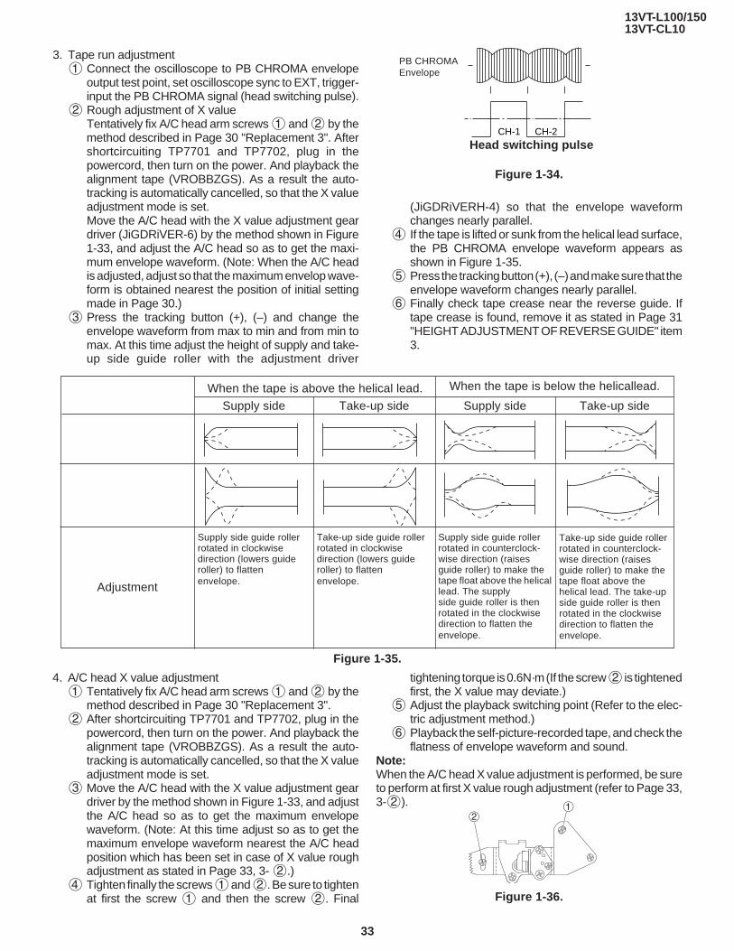
3. Tape run adjustment1 Connect the oscilloscope to PB CHROMA envelope
output test point, set oscilloscope sync to EXT, trigger-input the PB CHROMA signal (head switching pulse).
2 Rough adjustment of X valueTentatively fix A/C head arm screws 1 and 2 by themethod described in Page 30 "Replacement 3". Aftershortcircuiting TP7701 and TP7702, plug in thepowercord, then turn on the power. And playback thealignment tape (VROBBZGS). As a result the auto-tracking is automatically cancelled, so that the X valueadjustment mode is set.Move the A/C head with the X value adjustment geardriver (JiGDRiVER-6) by the method shown in Figure1-33, and adjust the A/C head so as to get the maxi-mum envelope waveform. (Note: When the A/C headis adjusted, adjust so that the maximum envelop wave-form is obtained nearest the position of initial settingmade in Page 30.)
3 Press the tracking button (+), (–) and change theenvelope waveform from max to min and from min tomax. At this time adjust the height of supply and take-up side guide roller with the adjustment driver
Figure 1-35.
4. A/C head X value adjustment1 Tentatively fix A/C head arm screws 1 and 2 by the
method described in Page 30 "Replacement 3".2 After shortcircuiting TP7701 and TP7702, plug in the
powercord, then turn on the power. And playback thealignment tape (VROBBZGS). As a result the auto-tracking is automatically cancelled, so that the X valueadjustment mode is set.
3 Move the A/C head with the X value adjustment geardriver by the method shown in Figure 1-33, and adjustthe A/C head so as to get the maximum envelopewaveform. (Note: At this time adjust so as to get themaximum envelope waveform nearest the A/C headposition which has been set in case of X value roughadjustment as stated in Page 33, 3- 2.)
4 Tighten finally the screws 1 and 2. Be sure to tightenat first the screw 1 and then the screw 2. Final
(JiGDRiVERH-4) so that the envelope waveformchanges nearly parallel.
4 If the tape is lifted or sunk from the helical lead surface,the PB CHROMA envelope waveform appears asshown in Figure 1-35.
5 Press the tracking button (+), (–) and make sure that theenvelope waveform changes nearly parallel.
6 Finally check tape crease near the reverse guide. Iftape crease is found, remove it as stated in Page 31"HEIGHT ADJUSTMENT OF REVERSE GUIDE" item3.
PB CHROMAEnvelope
CH-1 CH-2
Head switching pulse
Figure 1-34.
When the tape is above the helical lead. When the tape is below the helicallead.
Take-up side Supply side Take-up side
Adjustment
Supply side
Supply side guide rollerrotated in clockwisedirection (lowers guideroller) to flattenenvelope.
Take-up side guide rollerrotated in clockwisedirection (lowers guideroller) to flattenenvelope.
Supply side guide rollerrotated in counterclock-wise direction (raisesguide roller) to make thetape float above the helicallead. The supplyside guide roller is thenrotated in the clockwisedirection to flatten theenvelope.
Take-up side guide rollerrotated in counterclock-wise direction (raisesguide roller) to make thetape float above thehelical lead. The take-upside guide roller is thenrotated in the clockwisedirection to flatten theenvelope.
tightening torque is 0.6N·m (If the screw 2 is tightenedfirst, the X value may deviate.)
5 Adjust the playback switching point (Refer to the elec-tric adjustment method.)
6 Playback the self-picture-recorded tape, and check theflatness of envelope waveform and sound.
Note:When the A/C head X value adjustment is performed, be sureto perform at first X value rough adjustment (refer to Page 33,3-2).
Figure 1-36.
12
13VT-L100/15013VT-CL10
34
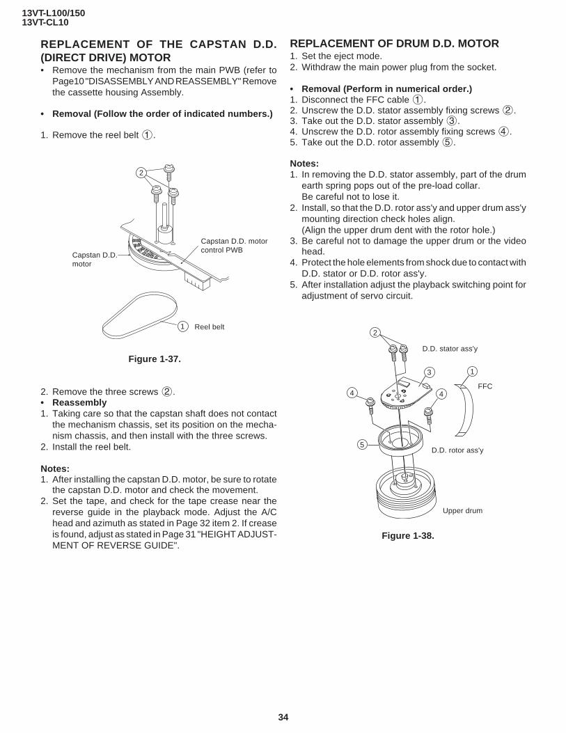
REPLACEMENT OF THE CAPSTAN D.D.(DIRECT DRIVE) MOTOR• Remove the mechanism from the main PWB (refer to
Page10 "DISASSEMBLY AND REASSEMBLY" Removethe cassette housing Assembly.
• Removal (Follow the order of indicated numbers.)
1. Remove the reel belt 1.
Figure 1-37.
2. Remove the three screws 2.• Reassembly1. Taking care so that the capstan shaft does not contact
the mechanism chassis, set its position on the mecha-nism chassis, and then install with the three screws.
2. Install the reel belt.
Notes:1. After installing the capstan D.D. motor, be sure to rotate
the capstan D.D. motor and check the movement.2. Set the tape, and check for the tape crease near the
reverse guide in the playback mode. Adjust the A/Chead and azimuth as stated in Page 32 item 2. If creaseis found, adjust as stated in Page 31 "HEIGHT ADJUST-MENT OF REVERSE GUIDE".
Capstan D.D.motor
Capstan D.D. motorcontrol PWB
2
1 Reel belt
REPLACEMENT OF DRUM D.D. MOTOR1. Set the eject mode.2. Withdraw the main power plug from the socket.
• Removal (Perform in numerical order.)1. Disconnect the FFC cable 1.2. Unscrew the D.D. stator assembly fixing screws 2.3. Take out the D.D. stator assembly 3.4. Unscrew the D.D. rotor assembly fixing screws 4.5. Take out the D.D. rotor assembly 5.
Notes:1. In removing the D.D. stator assembly, part of the drum
earth spring pops out of the pre-load collar.Be careful not to lose it.
2. Install, so that the D.D. rotor ass'y and upper drum ass'ymounting direction check holes align.(Align the upper drum dent with the rotor hole.)
3. Be careful not to damage the upper drum or the videohead.
4. Protect the hole elements from shock due to contact withD.D. stator or D.D. rotor ass'y.
5. After installation adjust the playback switching point foradjustment of servo circuit.
Figure 1-38.
2
4
3
4
5
1
D.D. stator ass'y
D.D. rotor ass'y
FFC
Upper drum
13VT-L100/15013VT-CL10
35
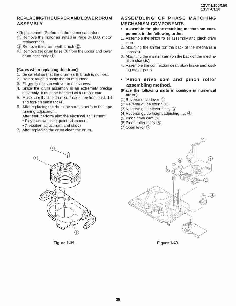
REPLACING THE UPPER AND LOWER DRUMASSEMBLY
• Replacement (Perform in the numerical order)1Remove the motor as stated in Page 34 D.D. motor
replacement.2Remove the drum earth brush 2.3Remove the drum base 3 from the upper and lower
drum assembly 1.
[Cares when replacing the drum]1. Be careful so that the drum earth brush is not lost.2. Do not touch directly the drum surface.3. Fit gently the screwdriver to the screws.4. Since the drum assembly is an extremely precise
assembly, it must be handled with utmost care.5. Make sure that the drum surface is free from dust, dirt
and foreign substances.6. After replacing the drum be sure to perform the tape
running adjustment.After that, perform also the electrical adjustment.• Playback switching point adjustment• X-position adjustment and check
7. After replacing the drum clean the drum.
Figure 1-39.
2
1
3
ASSEMBLING OF PHASE MATCHINGMECHANISM COMPONENTS• Assemble the phase matching mechanism com-
ponents in the following order.1. Assemble the pinch roller assembly and pinch drive
cam.2. Mounting the shifter (on the back of the mechanism
chassis).3. Mounting the master cam (on the back of the mecha-
nism chassis).4. Assemble the connection gear, slow brake and load-
ing motor parts.
• Pinch drive cam and pinch rollerassembling method.
(Place the following parts in position in numericalorder.)
(1)Reverse drive lever 1(2)Reverse guide spring 2(3)Reverse guide lever ass’y 3(4)Reverse guide height adjusting nut 4(5)Pinch drive cam 5(6)Pinch roller ass’y 6(7)Open lever 7
Figure 1-40.
7
4
3
2
6
1
5
13VT-L100/15013VT-CL10
36
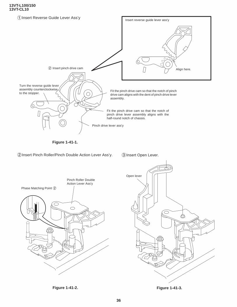
1Insert Reverse Guide Lever Ass’y
Figure 1-41-1.
Phase Matching Point 2
Pinch Roller DoubleAction Lever Ass'y
Open lever
Insert reverse guide lever ass'y
Align here.2 Insert pinch drive cam
Pinch drive lever ass'y
Fit the pinch drive cam so that the notch of pinchdrive cam aligns with the dent of pinch drive leverassembly.
Fit the pinch drive cam so that the notch ofpinch drive lever assembly aligns with thehalf-round notch of chassis.
Turn the reverse guide leverassembly counterclockwiseto the stopper.
2Insert Pinch Roller/Pinch Double Action Lever Ass’y.
Figure 1-41-2.
3Insert Open Lever.
Figure 1-41-3.

13VT-L100/15013VT-CL10
37
INSTALLING THE SHIFTER
Figure 1-42.
CapstanD.D. motor
Drum
Reel pulley
(Bottom side of mechanism chassis)
Sifter
Phase-Matchingpoint 2
Insertpoint 1
Half round notch
Shaft 1
Round mark
Loading gear (T)
Insertpoint 3
Insertpoint 2
Insertpoint 4
Insertpoint 6
Releasepoint 3
Shaft 1
Shaft 1
Shaft 4
Figure 1-43.
Rotationpoint 2
Phase-matchingpoint 1
1. Make sure that the loading gear is at the point 1 asshown below.
2. Install, paying attention to 6 insertion points and 3release points.
3. For the phase matching at the insertion point 1, seethe point 2 as shown below.
4. Finally fix the inserts 1 and 4.

13VT-L100/15013VT-CL10
38
INSTALLING THE MASTER CAM (AT REARSIDE OF MECHANISM CHASSIS)1. Make sure beforehand that the shifter is at the point as
shown below.2. Place the master cam in the position as shown below.
Note:See the figure below for the phase matching between themaster cam and the casecon drive gear.3. Finally fix with the E-ring.
Figure 1-44-2.
When installing the master cam,align the casecon drive gearround mark with the half-roundnotch of master cam.
E-ring(XRESJ30-06000)
Master cam
Fully turnclockwise
Fully turn counterclockwise
Figure 1-44-1.
Face the wide tooth side ward
Master cam
Casecon drive gear
Round mark
Half-round notch
10.2 mm+0.2–0.2
Apply grease
No grease
+0.2–0.2
REPLACEMENT OF LOADING MOTOR• Removal
• Replacement1. Remove the loading motor, and install the replace-
ment loading motor as shown below.
Figure 1-46.
The loading motor pressing-in must be less than 14.7N (15 gf).Adjust the distance between motor and pulley to 10.2 mm).
Figure 1-45.
Apply grease

13VT-L100/15013VT-CL10
39
2. Synchro Gear, Drive Gear L and Drive Gear R
ASSEMBLY OF CASSETTE HOUSING1. Drive Gear and R Drive angle ass’y
Figure 1-47.
MSPRT0381AJFJ
Apply grease
Apply grease
Apply grease
LANGF9592AJFW
Top surface should be free from scratches or soil.
Drive angle
Drive gear R
Frame
Figure 1-48.
13VT-L100/15013VT-CL10
40
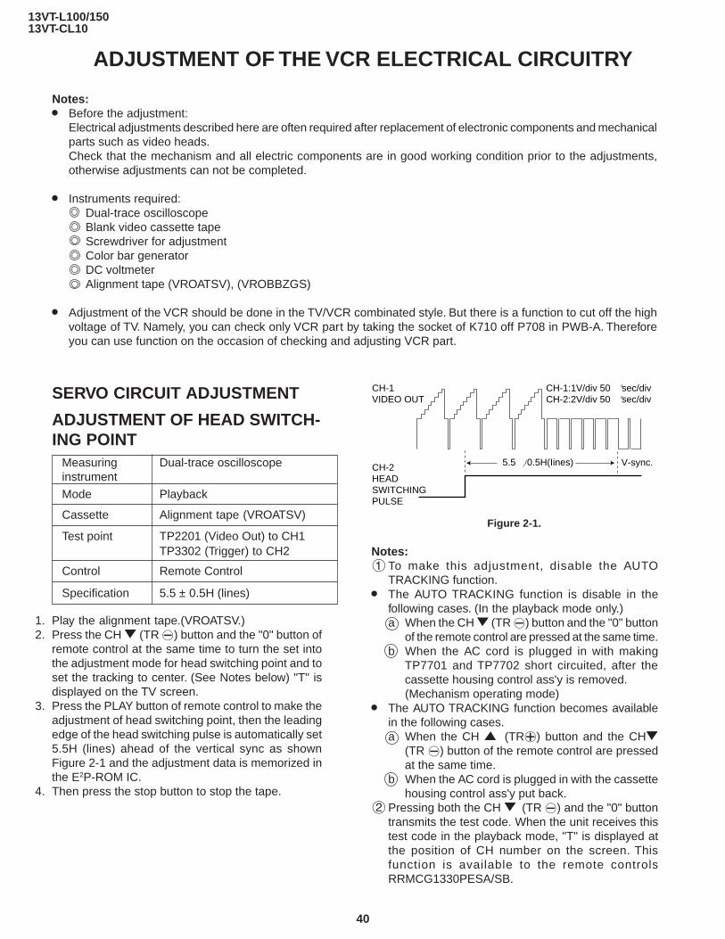
1. Play the alignment tape.(VROATSV.)2. Press the CH " (TR —) button and the "0" button of
remote control at the same time to turn the set intothe adjustment mode for head switching point and toset the tracking to center. (See Notes below) "T" isdisplayed on the TV screen.
3. Press the PLAY button of remote control to make theadjustment of head switching point, then the leadingedge of the head switching pulse is automatically set5.5H (lines) ahead of the vertical sync as shownFigure 2-1 and the adjustment data is memorized inthe E2P-ROM IC.
4. Then press the stop button to stop the tape.
ADJUSTMENT OF THE VCR ELECTRICAL CIRCUITRY
Notes:» Before the adjustment:
Electrical adjustments described here are often required after replacement of electronic components and mechanicalparts such as video heads.Check that the mechanism and all electric components are in good working condition prior to the adjustments,otherwise adjustments can not be completed.
» Instruments required:Dual-trace oscilloscopeBlank video cassette tapeScrewdriver for adjustmentColor bar generatorDC voltmeterAlignment tape (VROATSV), (VROBBZGS)
» Adjustment of the VCR should be done in the TV/VCR combinated style. But there is a function to cut off the highvoltage of TV. Namely, you can check only VCR part by taking the socket of K710 off P708 in PWB-A. Thereforeyou can use function on the occasion of checking and adjusting VCR part.
SERVO CIRCUIT ADJUSTMENT
ADJUSTMENT OF HEAD SWITCH-ING POINT
Measuring Dual-trace oscilloscopeinstrument
Mode Playback
Cassette Alignment tape (VROATSV)
Test point TP2201 (Video Out) to CH1TP3302 (Trigger) to CH2
Control Remote Control
Specification 5.5 ± 0.5H (lines)
Notes:1To make this adjustment, disable the AUTO
TRACKING function.» The AUTO TRACKING function is disable in the
following cases. (In the playback mode only.)a When the CH " (TR —) button and the "0" button
of the remote control are pressed at the same time.b When the AC cord is plugged in with making
TP7701 and TP7702 short circuited, after thecassette housing control ass'y is removed.(Mechanism operating mode)
» The AUTO TRACKING function becomes availablein the following cases.a When the CH ' (TR±) button and the CH"
(TR —) button of the remote control are pressedat the same time.
b When the AC cord is plugged in with the cassettehousing control ass'y put back.
2Pressing both the CH " (TR —) and the "0" buttontransmits the test code. When the unit receives thistest code in the playback mode, "T" is displayed atthe position of CH number on the screen. Thisfunction is available to the remote controlsRRMCG1330PESA/SB.
Figure 2-1.
5.5 }0.5H(Iines) V-sync.CH-2HEADSWITCHINGPULSE
CH-1VIDEO OUT
CH-1:1V/div 50 ˚sec/divCH-2:2V/div 50 ˚sec/div

13VT-L100/15013VT-CL10
41
Test points layout of Main Unit.
ADJUSTMENT OF EP STILL PIC-TURE VERTICAL SYNC
Measuring Monitor TVinstrument
Mode EP still picture playback
Input signal Self-recording tape
Test point Monitor screen
Control CH '/" (TR ±/ —) buttons
Specification No Vertical jitter
Figure 2-2.
1. Playback the EP Self-recorded tape in the still mode.2. Using the CH '/" (TR ±/ —) buttons on the remote
control or inside the front cover, make adjustment sothat the vertical jitter becomes minimum.
3. Then press the STOP button to stop the tape.
Note:The data of this adjustment is memorized to the E2P-ROM IC.

13VT-L100/15013VT-CL10
42
TROUBLESHOOTING OF VCR SECTION
Che
ck/r
epla
ce X
7701
an
d/or
IC77
01.
ELE
CT
RIC
AL
TR
OU
BLE
SH
OO
TIN
G
VC
R P
OW
ER
TR
OU
BLE
SH
OO
TIN
GF
LOW
CH
AR
T N
O.1
-1
The
VC
R is
dea
d.(N
o po
wer
)
Unp
lug
the
AC
pow
er c
ord.
Rep
lug
it a
few
min
utes
late
r.
Are
the
AT
5V
and
AT
12V
lin
es n
orm
al?
Are
the
AT
5V
and
GN
D
lines
pro
perly
con
nect
ed
with
IC77
01?
Is th
ere
osci
llatio
n (1
6MH
z) a
t pin
s (3
8) a
nd
(39)
of I
C77
01?
Doe
s th
e "L
" pu
lse
of s
ys-
con
rese
t app
ear
at p
in
(43)
of I
C77
01 a
fter
the
AC
cor
d is
plu
gged
in?
Doe
s pi
n (2
1) o
f IC
7701
ch
ange
from
"L"
to "
H"
leve
l whe
n th
e po
wer
bu
tton
is p
ress
ed to
turn
on
the
pow
er?
Are
the
PC
9V
and
PC
5V
lin
es n
orm
al?
Che
ck p
ower
circ
uit.
Che
ck p
oor
sold
erin
g.
Che
ck th
e si
gnal
line
of
sys-
con
rese
t all
the
way
up
to p
in (
33)
of IC
2001
.
Che
ck th
e po
wer
key
in
put t
o IC
2001
and
ser
ial
data
s/cl
ocks
bet
wee
n IC
2001
and
IC77
01.
Che
ck p
ower
circ
uit.
Che
ck th
e se
nsor
inpu
ts
to IC
7701
from
m
echa
nism
. (C
AM
sw
itche
s,st
art/e
nd
sens
ors,
and
reel
sen
sors
)
KE
Y-I
N T
RO
UB
LES
HO
OT
ING
FLO
W C
HA
RT
NO
.1-2
Key
-in in
put f
or V
CR
is n
ot r
ecei
ved.
Is th
e ke
y sw
itch
in g
ood
cont
act?
Is th
ere
shor
t-ci
rcui
t in
the
key
inpu
t?
Are
sig
nals
rec
eive
d at
pi
n (2
7) o
f IC
2001
whe
n th
e ke
y is
act
ivat
ed?
Che
ck IC
7701
, IC
2001
and
si
gnal
line
of s
eria
l dat
as,
seria
l clo
ck a
nd r
eady
(L)
.
Che
ck th
e sw
itch
cont
act.
Che
ck IC
2001
and
sw
itche
s fo
r po
or s
olde
ring.
Che
ck k
ey li
nes
to in
put
IC20
01.
YE
SY
ES
YE
S
YE
S
YE
S
YE
S
YE
S
YE
S
YE
S
YE
S
NO
NO
NO
NO
NO
NO
NO
NO
NO
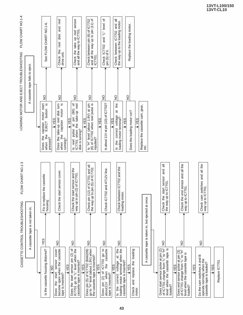
13VT-L100/15013VT-CL10
43
NO
NO
NO
NO
Che
ck p
in (
12)
of I
C77
01 a
nd a
ll th
e w
ay u
p to
pin
(5)
of I
C77
02.
NO
NO
CA
SS
ET
TE
CO
NT
RO
L T
RO
UB
LES
HO
OT
ING
FLO
W C
HA
RT
NO
.1-3
A c
asse
tte ta
pe is
not
take
n in
.
YE
S
YE
S
YE
S
YE
S
YE
S
YE
S
Fix
or
repl
ace
the
cass
ette
ho
usin
g.
Che
ck th
e st
art s
enso
r co
ver.
Che
ck th
e st
art s
enso
r an
d th
e w
ay u
p to
pin
(2)
of I
C77
01.
NO
NO
NO
YE
S
YE
S
YE
S
Che
ck IC
7702
and
AT
12V
line
.
Che
ck b
etw
een
IC77
02 a
nd th
e lo
adin
g m
otor
.
A c
asse
tte ta
pe is
take
n in
, but
eje
cted
at o
nce.
Rep
lace
IC77
01
Is th
e ca
sset
te h
ousi
ng d
isto
red?
Doe
s th
e st
art
sens
or
cove
r be
com
e op
en w
hen
the
cass
ette
ta
pe is
inse
rted
?
Doe
s th
e st
art
sens
or p
in (
2) o
f IC
7701
go
to "
L" l
evel
whe
n th
e ca
sset
te ta
pe is
inse
rted
?
Doe
s pi
n (5
) of
IC
7702
(B
A62
09)
go to
"H
" le
vel (
abou
t 1.8
V)
whe
n th
e ca
sset
te ta
pe is
inse
rted
?
Che
ck a
nd r
epla
ce t
he l
oadi
ng
mot
or.
Is
the
corr
ect
volta
ge
at
the
load
ing
mot
or t
erm
inal
whe
n th
e ca
sset
te ta
pe is
inse
rted
?
Doe
s pi
n (2
) of
IC
7702
go
to
ab
out1
1V
whe
n th
e ca
sset
te
tape
is in
sert
ed?
Do
the
cam
sw
itche
s A
and
B
oper
ate
norm
ally
whe
n th
e ca
sset
te ta
pe is
load
ed?
Doe
s en
d se
nsor
pul
se a
t pin
(3)
of
IC77
01 c
hang
e fr
om "
L" to
"H
" le
vel w
hen
the
cass
ette
tape
is
load
ed?
Doe
s st
art s
enso
r pu
lse
at p
in (
2)
of I
C77
01 c
hang
e fr
om "
L" t
o "H
" le
vel
whe
n th
e ca
sset
te t
ape
is
load
ed?
Che
ck t
he s
tart
sen
sor
and
all
the
way
up
to IC
7701
.
Che
ck t
he e
nd s
enso
r an
d al
l the
w
ay u
p to
IC77
01.
Che
ck c
am s
witc
hes
and
all
the
way
up
to IC
7701
.
FLO
W C
HA
RT
NO
.1-4
NO
NO
NO
NO
NO
NO
NO
YE
S
YE
S
YE
S
YE
S
YE
S
YE
S
YE
S
See
FLO
W C
HA
RT
NO
.1-6
.
Rep
lace
the
load
ing
mot
or.
Che
ck
the
reel
di
sk
and
reel
dr
ive
unit.
Che
ck t
he t
ake
up r
eel
sens
or
and
all t
he w
ay to
IC77
01.
Che
ck b
etw
een
pin
(6)
of IC
7702
an
d al
l th
e w
ay u
p to
pin
(11
) of
IC
7701
.
Che
ck I
C77
02 a
nd "
L" l
evel
of
pin
(5)
of it
.
Che
ck b
etw
een
IC77
02 a
nd a
ll th
e w
ay u
p to
the
load
ing
mot
or.
LOA
DIN
G M
OT
OR
AN
D E
JEC
T T
RO
UB
LES
HO
OT
ING
A c
asse
tte ta
pe fa
ils to
eje
ct.
Doe
s th
e ca
psta
n m
otor
st
art
wh
en
th
e
EJE
CT
b
utt
on
is
pr
esse
d?
Doe
s th
e ta
ke-u
p re
el d
isk
turn
w
he
n
the
ca
pst
an
m
oto
r is
ru
nnin
g?
Is
reel
pu
lse
at
pin
(80)
of
IC
7701
whe
n th
e ta
ke-u
p re
el
disk
is tu
rnin
g?
Is "
H"
leve
l (a
bout
1.8
V)
at p
in
(6)
of I
C77
02 w
hen
reel
pul
se i
s in
putte
d?
Is a
bout
11V
at p
in (1
0) o
f IC
7702
?
Is
the
corr
ect
volta
ge
at
the
load
ing
mot
or te
rmin
al?
Doe
s th
e lo
adin
g m
otor
run
?
Rep
lace
the
cass
ette
cam
, gea
r,
etc.

13VT-L100/15013VT-CL10
44
NO
NO
NO
NO
NO
SY
ST
EM
CO
NT
RO
L T
RO
UB
LES
HO
OT
ING
FLO
W C
HA
RT
NO
.1-5
FLO
W C
HA
RT
NO
.1-6
No
pow
er.
YE
S
YE
S
YE
S
YE
S
YE
S
NO
NO
NO
NO
YE
S
YE
S
YE
S
YE
S
Che
ck IC
2001
and
IC77
01.
Che
ck IC
7701
.
Che
ck IC
765
(PC
9V G
EN
.)
Che
ck Q
756
(PC
5V G
EN
.)
Che
ck th
e A
T5V
line
.
Che
ck p
in (
74)
of IC
7701
Che
ck th
e A
T8V
line
or
the
AT
12V
line
.
Doe
s po
wer
con
trol
(H
) si
gnal
at
pin
(21)
of
IC77
01 c
hang
e fr
om
"L"
to"H
" le
vel?
Che
ck p
erip
hera
l ci
rcui
t fo
r po
or
sold
erin
g of
P
C9V
an
d P
C5V
lin
es.
Are
se
rial
cl
ock
puls
e an
d T
V
data
pul
se a
pplie
d to
pin
s (6
7)
and
(66)
of I
C77
01 fr
om IC
2001
?
Are
sy
stem
co
ntro
l da
ta
puls
e an
d sy
stem
con
trol
rea
dy p
ulse
ap
plie
d to
pin
s (3
6) a
nd (
35)
of
IC20
01 fr
om IC
7701
?
Ch
eck
b
etw
ee
n
the
M
C
con
ne
cto
r a
nd
IC
77
01
, a
nd
be
twee
n th
e M
C c
onne
ctor
and
pi
n (7
5) o
f IC
7701
.
CA
PS
TA
N M
OT
OR
TR
OU
BLE
SH
OO
TIN
G
The
cap
stan
mot
or fa
ils to
run
.
Is t
he v
olta
ge m
ore
than
abo
ut
2.6V
gi
ven
to
pin
(4)
of
AC
co
nnec
tor?
Is t
he v
olta
ge a
t pi
n (3
) of
AC
co
nnec
tor
1.8~
2.7V
?
Is 5
V a
t pin
(8)
of A
C c
onne
ctor
?
Che
ck/r
epla
ce th
e ca
psta
n m
otor
.
Is th
e P
C5V
line
nor
mal
?
Is th
e P
C9V
line
nor
mal
?
Is 8
V o
r 12
V a
t pin
(5)
of A
C
conn
ecto
r?

13VT-L100/15013VT-CL10
45
TA
KE
-UP
RE
EL
PU
LSE
GE
NE
RA
TO
R T
RO
UB
LES
HO
OT
ING
FLO
W C
HA
RT
NO
.1-7
HE
AD
SW
ITC
HIN
G P
ULS
E T
RO
UB
LES
HO
OT
ING
FLO
W C
HA
RT
NO
.1-8
FLO
W C
HA
RT
NO
.1-9
No
reel
sen
sor
puls
e ap
pear
s.
No
head
sw
itchi
ng p
ulse
.
YE
SN
O
NO
NO
NO
NO
YE
S
YE
S
YE
S
Che
ck th
e A
T12
V li
ne.
Inse
rt th
e ca
sset
te, a
nd
put t
he u
nit i
n F
F o
r R
EW
m
ode.
Rep
lace
the
take
up
/sup
ply
reel
sen
sors
D
7702
/D77
03.
Che
ck th
e ha
rnes
s A
D-M
E a
nd th
e dr
um
mot
or u
nit.
Che
ck p
in (
18)
of IC
7701
an
d si
gnal
line
of h
ead
switc
hing
pul
se.
Che
ck a
ll th
e w
ay u
p to
pi
ns (
86)
and
(87)
of
IC77
01.
Che
ck b
etw
een
the
ME
soc
ket
and
pin
(78)
of I
C77
01, a
nd
betw
een
the
ME
soc
ket a
nd p
in
(76)
of I
C77
01.
YE
S
YE
S
YE
S
NO
NO
NO
DR
UM
MO
TO
R T
RO
UB
LES
HO
OT
ING
The
dru
m m
otor
fails
to r
un.
Is th
e vo
ltage
mor
e th
an a
bout
2.
6V a
pplie
d at
pin
(1)
of M
E
conn
ecto
r.
Che
ck b
etw
een
the
ME
co
nnec
tor
and
all t
he w
ay u
p to
pi
n (8
6) o
f IC
7701
.
Is 5
V a
t pin
(7)
of M
E c
onne
ctor
?
Che
ck/r
epla
ce th
e dr
um m
otor
.
Is 1
2V a
t pin
(4)
of M
E c
onne
ctor
?
Che
ck th
e A
T 5
V li
ne.
NO
NO
NO
YE
S
YE
S
YE
S
Che
ck o
r re
plac
e IC
7701
.
The
dru
m m
otor
run
s on
ly fo
r a
few
sec
onds
.
Che
ck p
in (
76)
of IC
7701
.
Che
ck th
e dr
um m
otor
.
Are
ther
e th
e ta
ke
up/s
uppl
y re
el p
ulse
s at
th
e co
llect
ors
of
D77
02/D
7703
.
Are
the
drum
PG
and
dr
um F
G s
igna
l inp
utte
d to
pin
s (8
6) a
nd (
87)
of
IC77
01, r
espe
ctiv
ely?
Are
ther
e th
e dr
um P
G
and
drum
FG
Sig
nals
at
pins
(3)
and
(5)
of
conn
ecto
r A
D?
Che
ck
betw
een
D77
02
and
pin
(80)
of
IC77
01,
betw
een
D77
03 a
nd p
in
(79)
of I
C77
01.
Is th
e dr
um m
otor
ro
tatin
g?
Is d
rum
PG
sig
nal a
t pin
(86
) of
IC
7701
?
Is d
rum
PG
sig
nal a
t pin
(5)
of
ME
con
nect
or?
IS H
.SW
. pul
se a
t pin
(18
) of
IC
7701
?
See
FLO
W C
HA
RT
NO
. 1-
9.
4.2 4.
40
0
D-P
G
D-F
Gabou
t4.
5Vp-
p

13VT-L100/15013VT-CL10
46
NO
NO
NO
NO
NO
NO
NO
NO
DR
UM
SE
RV
O T
RO
UB
LES
HO
OT
ING
FLO
W C
HA
RT
NO
.1-1
0
Dru
m s
ervo
doe
s no
t fun
ctio
n.
YE
S
YE
S
YE
S
YE
S YE
S
YE
S
YE
S
YE
S
See
FLO
W C
HA
RT
NO
. 1-
8.
Is p
in (
76)
of IC
7701
in
high
impe
danc
e?
Rep
lace
IC77
01.
Rep
lace
IC77
01.
Che
ck X
7701
, C77
05 a
nd
C77
06.
Che
ck th
e si
gnal
line
of
drum
PG
.
Is t
here
16M
Hz
osci
llatio
n at
pin
s (3
8) a
nd (
39)
of
IC77
01?
Is th
ere
the
durm
PG
si
gnal
at p
in (
86)
of
IC77
01?
Che
ck th
e co
mpo
site
sy
nc. s
igna
l at p
in (
14)
of
IC22
01, Q
2201
and
Q
2202
.
Is th
ere
the
head
sw
itchi
ng p
ulse
at p
in (
18)
of IC
7701
?
Is th
ere
the
drum
FG
si
gnal
at p
in (
87)
of
IC77
01?
Is th
ere
the
drum
con
trol
ou
tput
at p
in (
78)
of
IC77
01?
Che
ck th
e si
gnal
line
be
twee
n pi
n (7
) of
AD
an
d pi
n (7
6) o
f IC
7701
.
Che
ck P
G a
nd F
G to
pin
s (5
) an
d (3
) of
the
conn
ecto
r M
E a
nd th
e dr
um m
otor
.
Is th
ere
the
drum
con
trol
vo
ltage
app
lied
to p
in (
1)
of M
E c
onne
ctor
?
Che
ck A
T 1
2V a
t pin
(4)
an
d A
T 5
V a
t pin
(7)
of
ME
con
nect
or.
Che
ck a
nd r
epla
ce th
e dr
um m
otor
.
Is th
ere
the
refe
renc
e si
gnal
(V
-syn
c.)
at p
in
(84)
of I
C77
01?
In R
EC
mod
eIn
PB
mod
e

13VT-L100/15013VT-CL10
47
NO
NO
NO
NO
NO
NO
NO
NO
CA
PS
TA
N S
ER
VO
TR
OU
BLE
SH
OO
TIN
GF
LOW
CH
AR
T N
O.1
-11
YE
S
YE
S
YE
S
YE
S
NO
NO
YE
S
YE
S
YE
S
YE
S
YE
S
YE
S
YE
S
YE
S
NO
Is p
in (
75)
of IC
7701
no
rmal
?
Rep
lace
the
caps
tan
mot
or.
Rep
lace
IC77
01.
Rep
lace
IC77
01.
Rep
lace
the
FF
C A
A-M
H.
Che
ck X
7701
, C77
05 a
nd
C77
06.
Che
ck th
e ca
psta
n F
G
sign
al li
ne b
etw
een
AM
co
nnec
tor
and
IC77
01.
Doe
s th
ere
appe
ar th
e ca
psta
n F
G s
igna
l at p
in
(85)
of I
C77
01?
Is th
ere
the
caps
tan
cont
rol v
olta
ge a
pplie
d to
pi
n (4
) of
AC
con
nect
or?
Che
ck th
e co
mpo
site
sy
nc. s
igna
l at p
in (
14)
of
IC22
01, Q
2201
and
Q
2202
, up
to p
in (
84)
of
IC77
01.
Rep
lace
IC77
01.
Rep
lace
A/C
hea
d.
Che
ck "
A "
Che
ck "
B "
In c
ase
of N
O G
OO
D
Doe
s th
ere
appe
ar th
e V
-syn
c. a
t pin
(84
) at
IC
7701
?
Is th
ere
RE
C C
TL
sign
al
outp
ut a
t pin
s (9
2), (
91)
of
IC77
01?
Is th
ere
caps
tan
cont
rol
sign
al a
t pin
(77
) of
IC
7701
?
Are
RE
C a
nd /o
r P
B
mod
e in
oper
ativ
e?
Is th
e F
FC
AA
-MH
no
rmal
?
Doe
s th
e A
/C h
ead
oper
ate
norm
ally
?
Adj
ust t
he h
eigh
t of t
he
A/C
hea
d.
Doe
s P
B C
TL
sign
al
appe
ar a
t pin
(97
) of
IC
7701
?
Doe
s C
TL
ampl
ifier
circ
uit
of IC
7701
(pi
ns (
92)
to
(97)
) op
erat
e no
rmal
ly?
(Doe
s th
e no
ise
appe
ar a
t pi
n (9
7) w
hen
touc
h R
7774
by
hand
?)
Onl
y P
B m
ode
inop
eret
ive.
Onl
y R
EC
mod
e in
oper
etiv
e.A
B
Is th
ere
16M
Hz
osci
llatio
n at
pin
s (3
8) a
nd (
39)
of
IC77
01.
Cap
stan
ser
vo d
oes
not f
unct
ion.

13VT-L100/15013VT-CL10
48
NO
NO
NO
NO
NO
NO
NO
PLA
YB
AC
K M
OD
E T
RO
UB
LES
HO
OT
ING
FLO
W C
HA
RT
NO
.1-1
4
Pla
ybac
k is
not
pos
sibl
e.
YE
SY
ES
YE
S
YE
S
YE
S
YE
S
YE
S
Is t
he s
uppl
y vo
ltage
of
5V
feed
to p
in (
36)
of IC
3301
?C
heck
PC
5V li
ne.
Che
ck H
.SW
.P. l
ine.
Rep
lace
IC33
01.
Rep
lace
IC22
01.
Is t
here
a s
igna
l at
pin
(30
) of
IC33
01?
Is t
here
a s
igna
l at
pin
(57
) of
IC22
01?
Is t
here
a s
igna
l at
pin
(27
) of
IC22
01?
Is th
ere
a si
gnal
at p
in (
25)
of IC
2201
?
Che
ck b
etw
een
pin
(25)
of I
C22
01 a
nd a
ll th
e w
ay u
p th
ru p
in (
14)
of IC
402.
Che
ck p
erip
hera
l ci
rcui
ts o
f X
5502
.
Che
ck b
etw
een
pin
(30)
of
IC33
01 a
nd a
ll th
e w
ay u
p th
rn to
pin
(57
) of
IC22
01.
Che
ck t
he I
2 C b
us d
ata
and
cloc
k at
pin
s (8
) an
d (7
) of
IC
2201
.
Is t
here
a s
igna
l at
pin
(12
) of
IC22
01?
Is th
ere
H.S
W.P
. at p
in (
1) o
f IC
3301
?
⟨LU
MIN
AN
CE
⟩⟨C
HR
OM
INA
NC
E⟩
Pla
ybac
k is
pos
sibl
e bu
tw
ithou
t col
or.
NO
NO
E-E
MO
DE
TR
OU
BLE
SH
OO
TIN
GF
LOW
CH
AR
T N
O.1
-12
No
E-E
sig
nal.
YE
S
YE
S
YE
S
YE
S
YE
S
Che
ck b
etw
een
pins
(8)
an
d (7
) of
IC22
01 a
nd a
ll th
e w
ay u
p th
rn to
pin
s (5
2) a
nd (
51)
of IC
7701
.
NO
NO
NO
Is th
ere
a si
gnal
at p
in
(20)
or
(16)
of I
C22
01?
Is th
ere
a si
gnal
at p
in
(47)
of I
C40
1?
Is th
ere
a si
gnal
at p
in
(25)
of I
C22
01?
Che
ck P
C 5
V li
nes.
Rep
lace
IC22
01.
Che
ck IC
401
and
part
s ar
ound
it.
Che
ck b
etw
een
pin
(47)
of I
C40
1 an
d al
l the
way
up
thru
to
pin
(20)
or
(16)
of I
C22
01.
Is t
he s
uppl
y vo
ltage
of
5V f
eed
to p
ins
(4),
(21
),
(48)
and
(63
) of
IC22
01?
Are
ther
e th
e I2
C b
us
data
and
clo
ck a
t pin
s (8
) an
d (7
) of
IC22
01?
Che
ck b
etw
een
pin
(25)
of
IC22
01 a
nd p
in (
14)
of
IC40
2.
FLO
W C
HA
RT
NO
.1-1
3
NO
NO
NO
NO
NO
NO
NO
YE
S
YE
S
YE
S
YE
S
YE
SY
ES
YE
SY
ES
RE
CO
RD
ING
MO
DE
TR
OU
BLE
SH
OO
TIN
G
Rec
ordi
ng (
LUM
INA
NC
E)
is n
ot p
ossi
ble.
Rec
ordi
ng is
pos
sibl
e bu
t with
out c
olor
.
Is th
ere
a si
gnal
at
pin
(29)
of
IC22
01?
Is th
ere
a si
gnal
at
pin
(57)
of I
C22
01?
Che
ck p
arts
ar
ound
and
pin
s (2
7), (
38),
(36
) an
d (2
9) o
f IC
2201
.
Che
ck p
arts
ar
ound
pin
s (3
0)
and
(31)
of
IC22
01.
Is th
ere
a si
gnal
at
pin
(10)
of
IC22
01?
Is th
ere
a si
gnal
at
pin
(57)
of
IC22
01?
Che
ck p
in (
94)
of
IC22
01.
(VC
O c
ontr
ol)
Che
ck p
arts
ar
ound
pin
s (1
2),
(43)
, (45
) an
d (1
0)
of IC
2201
.
Is th
ere
a si
gnal
at p
in (
26)
of IC
3301
?
Are
pin
s (3
6) a
nd (
35)
of IC
3301
at 5
V?
Is th
ere
a si
gnal
at p
in (
10)
of IC
3301
?
Che
ck u
pper
and
low
er d
rum
.
Che
ck P
C 5
V a
nd b
ias
CT
L (H
) lin
es.
Rep
lace
IC33
01.
Che
ck b
etw
een
pin
(57)
of I
C20
01 a
nd a
ll th
e w
ay u
p th
ru p
in (
26)
of IC
3301
.

13VT-L100/15013VT-CL10
49
SO
UN
D E
-E M
OD
E T
RO
UB
LES
HO
OT
ING
FLO
W C
HA
RT
NO
.1-1
5F
LOW
CH
AR
T N
O.1
-16
No
E-E
sig
nal
YE
S
YE
S
YE
S
YE
S
NO
YE
S
NO
NO
NO
NO
NO
YE
S
YE
S
YE
S
YE
S
YE
S
YE
S
Are
ther
e th
e I2
C b
us d
ata
and
cloc
k si
gnal
at p
ins
(8)
and
(7)
of IC
2201
?
Che
ck c
ircui
ts a
roun
d th
e au
dio
outp
ut
circ
uit i
n tu
ner
(TU
51)
and
part
s ar
ound
the
audi
o in
puts
jack
(J4
01).
Che
ck b
etw
een
pins
(8)
and
(7)
of I
C22
01
and
all t
he w
ay th
ru to
pin
s (5
2) a
nd (
51)
of
IC77
01.
NO
NO
NO
NO
SO
UN
D R
EC
OR
DIN
G M
OD
E T
RO
UB
LES
HO
OT
ING
No
reco
rd.
Che
ck P
C 5
V li
ne.
Is th
ere
"H"
leve
l at p
in (
72)
of IC
2201
?
Che
ck A
-MU
TE
(H
) Li
ne. (
IC22
01 p
in (
72)~
IC
7701
pin
(50
)).
Rep
lace
IC
2201
.
Che
ck th
e I2
C
bus
data
and
cl
ock
sign
al li
ne.
Rep
lace
IC
2201
.
Is th
ere
a si
gnal
at p
in (
87)
or
(91)
of I
C22
01?
Is th
e su
pply
vol
tage
of 5
V
feed
to p
in (
84)
of IC
2201
?
Is th
ere
a si
gnal
at p
in (
85)
of
IC22
01?
Che
ck b
etw
een
pin
(85)
of I
C22
01 a
nd p
in (
1) o
f IC
402.
Is v
olta
ge o
f pin
s (8
6) a
nd (
88)
of IC
2201
no
rmal
?
Is th
ere
"H"
leve
l at p
in (
70)
of
IC22
01?
Che
ck B
IAS
CT
L (H
) lin
e.
Che
ck P
C 9
V li
ne.
Is th
ere
a si
gnal
at p
in (
81)
of
IC22
01?
Is th
ere
"H"
leve
l at p
in (
2) o
f T
6601
?
Is th
ere
a si
gnal
(B
ias)
at p
in (
6) o
f T
6601
?C
heck
T66
01, Q
6603
, Q66
04 a
nd
thei
r pe
riphe
ral p
arts
.
Is th
ere
a si
gnal
(B
ias+
Aud
io s
ig.)
at
pin
(4)
of c
onne
ctor
AA
?
Che
ck th
e si
gnal
line
bet
wee
n pi
n (4
) of
con
nect
or A
A a
nd p
in (
81)
of
IC22
01, a
nd p
in (
6) o
f T66
01.N
OY
ES
Afte
r th
ere
the
I2C
bus
dat
a an
d cl
ock
sign
al a
t pin
s (8
) an
d (7
) of
IC
201?
Che
ck F
FC
MH
-AA
and
A/C
hea
d.

13VT-L100/15013VT-CL10
50
SO
UN
D P
LAY
BA
CK
MO
DE
TR
OU
BLE
SH
OO
TIN
GF
LOW
CH
AR
T N
O.1
-17
No
play
back
.
YE
S
YE
S
YE
S
YE
S
YE
S
YE
S
NO
NO
NO
NO
NO
NO
NO
Is th
ere
a si
gnal
at p
in (
74)
of
IC22
01?
Is th
ere
"L"
leve
l at p
in (
72)
of
IC22
01?
Is th
ere
a si
gnal
at p
in (
85)
of
IC22
01?C
heck
BIA
S C
TL
(H)
line.
Rep
lace
def
ectiv
e pa
rts.
Rea
djus
t azi
mut
h an
d he
ight
.
Rep
lace
A/C
hea
d.
Che
ck A
UD
IO M
UT
E (
H)
line.
Rep
lace
IC22
01.
Is th
ere
"L"
leve
l at p
in (
70)
of
IC22
01?
Are
azi
mut
h an
d he
ight
of t
he A
/C
head
pro
perly
adj
uste
d?
Che
ck li
ne b
etw
een
pin
(85)
of I
C22
01 p
in (
1) o
f IC
402.
Are
the
FF
C M
H-A
A a
nd th
e P
B
AM
P's
per
iphe
ral p
arts
aro
und
pins
(7
5)~
(78)
of I
C22
01 n
orm
al?
Cle
an A
/C h
ead.

13VT-L100/15013VT-CL10
51
NO
NO
NO
NO
FLO
W C
HA
RT
NO
.2-1
FLO
W C
HA
RT
NO
.2-2
Set
not
ope
ratin
g
YE
S
YE
S
YE
S
YE
S
YE
S
Is 1
20V
AC
app
lied
to
line
betw
een
K70
1 an
d K
702?
Pin
(7)
of T
701
volta
ge
chec
k ab
out:
170V
DC
at
120
V A
C
+B
vol
tage
che
ck
abou
t: 11
5.0V
(C
730
⊕
side
)
Doe
s pu
lse
wav
efor
m
exis
t at l
ine
betw
een
pin
(2)
and
(3)
of IC
701?
Che
ck D
701
thru
D
704,
L70
1, a
nd
R70
1.
Is A
C c
ord
conn
ecte
d?
Is 1
70V
DC
app
lied
to
C70
5?
Che
ck T
701
and
adja
cent
par
ts.
Is 1
6V D
C a
pplie
d to
pi
n (4
) of
IC70
1?C
heck
IC70
1, R
717.
Che
ck IC
701
and
adja
cent
par
ts.
CR
T c
onne
ctor
G
C1~
GC
5 bi
as c
heck
The
Fus
e is
aga
in
blow
n ou
t.
D70
1, D
702,
D70
3,
D70
4, D
705
Con
nect
AC
cor
d.F
701
Che
ck
Nor
mal
Nor
mal
IC70
1, C
heck
Nor
mal
Abn
omal
IC40
1 (iX
3253
CE
)
Nor
mal
Nor
mal
C85
4
Blo
wn
out
Rep
lace
the
Fus
e
Abn
orm
al
R70
1
Abn
orm
al
IC70
1, D
727
Nor
mal
Q60
1, Q
602
and
R60
3
AC
cor
d br
oken
.
NO
RA
ST
ER
TROUBLESHOOTING OF TV SECTION

13VT-L100/15013VT-CL10
52
NO
FLO
W C
HA
RT
NO
.2-3
FLO
W C
HA
RT
NO
.2-4
NO
PIC
TU
RE
, NO
SO
UN
D
YE
SY
ES
YE
S
YE
S
YE
SY
ES
YE
S
Che
ck
the
IC40
1 an
d ad
jace
nt
part
s.
Che
ck t
he I
C40
1 an
d ad
jace
nt p
arts
.
Che
ck th
e Q
404,
Q
433
and
adja
cent
pa
rts.
Che
ck th
e C
RT
co
nnec
tor
K1~
K6
and
adja
cent
par
ts.
Pin
(22
) of
IC40
1 bi
as
chec
k.
IC50
1 (L
A78
30)
bias
ch
eck.
D50
2, C
509,
C51
0 an
d R
511
Ver
tical
freq
che
ck
CF
631
(503
kHz)
Nor
mal
Abn
orm
al
IC40
1
Abn
orm
al
Abn
orm
al
Nor
mal
Nor
mal
NO
NO
NO
NO
NO
NO
NO
VE
RT
ICA
L S
CA
NC
ircui
t to
be c
heck
ed:
1. T
UN
ER
2. P
IF3.
Aut
omat
ic g
ain
cont
rol
4. 9
V p
ower
sou
rce
Che
ck th
e IC
401
and
adja
cent
par
ts
Che
ck IC
2001
.
Che
ck th
e tu
ner
AG
C.
Che
ck
the
IC35
1.
Doe
s th
e no
ise
leve
l inc
reas
e at
max
, C
ontr
ast,
Brig
htne
ss, a
nd S
ound
Con
trol
?
Is t
here
a s
igna
l at
pin
(43)
of I
C40
1?
Noi
se in
crea
ses
but
no s
igna
l is
rece
ived
Is th
ere
a si
gnal
at p
in
(41)
of I
C40
1?
Pic
ture
noi
se
decr
ease
but
sou
nd
leve
l var
ies
grea
tly.
Che
ck th
e tu
ner
bias
.
Nor
mal
Abn
orm
al
Abn
orm
al
Che
ck IC
401.
Nor
mal
Che
ck th
e T
uner
circ
uit.
Abn
orm
al
Che
ck th
e P
C9V
line
.
Nor
mal
Che
ck IC
401.
Doe
s th
e 9V
(+
B)
appe
ar a
t pin
(48
) of
IC40
1?
Is t
here
a s
igna
l at
pi
n (3
7) o
f IC
401?
Is
the
re a
sig
nal
at
pin
(53)
of I
C40
1.
Is th
ere
a si
gnal
at
pin
(8
) of
IC
351
(TD
A
7233
)?
Is th
ere
a si
gnal
at
pin
(5
) of
IC
351?
Che
ck
the
spea
ker.
Che
ck
the
IC40
1,
and
adja
cent
pa
rts.
Is th
ere
a si
gnal
at
pin
(5
4) o
f IC
401?
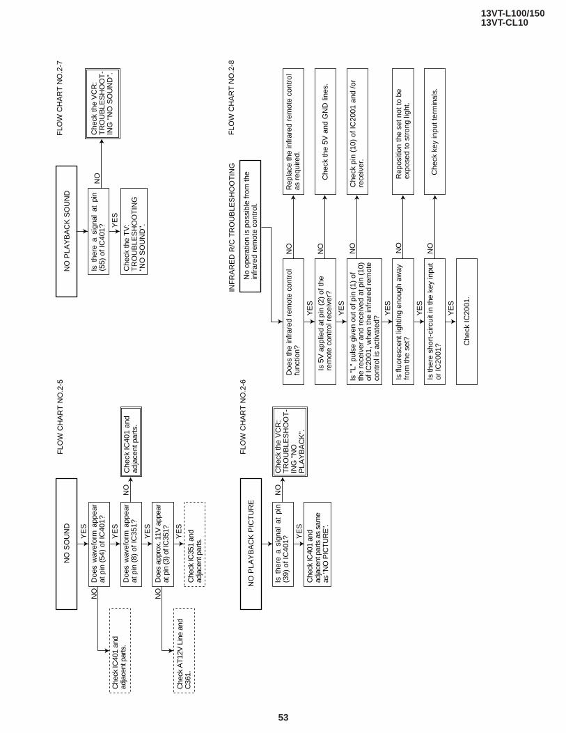
13VT-L100/15013VT-CL10
53
FLO
W C
HA
RT
NO
.2-5
FLO
W C
HA
RT
NO
.2-7
NO
SO
UN
D
FLO
W C
HA
RT
NO
.2-6
NO
PLA
YB
AC
K P
ICT
UR
E
YE
S
YE
S
YE
S
YE
S
YE
SY
ES
YE
S
YE
S
YE
S
YE
S
YE
S
Is t
here
a s
igna
l at
pin
(5
5) o
f IC
401?
Che
ck th
e T
V:
TR
OU
BLE
SH
OO
TIN
G
"NO
SO
UN
D".
NO
NO
NO
NO
PLA
YB
AC
K S
OU
ND
Che
ck IC
401
and
adja
cent
par
ts.
Che
ck th
e V
CR
: T
RO
UB
LES
HO
OT
-IN
G "
NO
SO
UN
D".
FLO
W C
HA
RT
NO
.2-8
Doe
s th
e in
frar
ed r
emot
e co
ntro
l fu
nctio
n?
Is 5
V a
pplie
d at
pin
(2)
of t
he
rem
ote
cont
rol r
ecei
ver?
Is fl
uore
scen
t lig
htin
g en
ough
aw
ay
from
the
set?
Is th
ere
shor
t-ci
rcui
t in
the
key
inpu
t or
IC20
01? C
heck
IC20
01.
Che
ck th
e 5V
and
GN
D li
nes.
Che
ck k
ey in
put t
erm
inal
s.
Rep
lace
the
infr
ared
rem
ote
cont
rol
as r
equi
red.
Che
ck p
in (
10)
of IC
2001
and
/or
rece
iver
.
Rep
ositi
on th
e se
t not
to b
e ex
pose
d to
str
ong
light
.
Is "
L" p
ulse
giv
en o
ut o
f pin
(1)
of
the
rece
iver
and
rec
eive
d at
pin
(10
) of
IC20
01, w
hen
the
infr
ared
rem
ote
cont
rol i
s ac
tivat
ed?
No
oper
atio
n is
pos
sibl
e fr
om th
ein
frar
ed r
emot
e co
ntro
l.
Doe
s w
avef
orm
app
ear
at p
in (
8) o
f IC
351?
Che
ck IC
351
and
adja
cent
par
ts.
Che
ck IC
401
and
adja
cent
par
ts.
Che
ck A
T12V
Lin
e an
d C
361.
Doe
s ap
prox
. 11V
app
ear
at p
in (3
) of I
C35
1?
Che
ck IC
401
and
adja
cent
par
ts a
s sa
me
as "N
O P
ICTU
RE
".
Doe
s w
avef
orm
app
ear
at p
in (
54)
of IC
401?
NO
NO
NO
NO
NO
NO
NO
Che
ck th
e V
CR
: T
RO
UB
LES
HO
OT
-IN
G "
NO
P
LAY
BA
CK
".
Is t
here
a s
igna
l at
pin
(3
9) o
f IC
401?
INF
RA
RE
D R
/C T
RO
UB
LES
HO
OT
ING

54
13VT-L100/15013VT-CL10
A
B
C
D
E
F
G
H
I
J
1 2 3 4 5 6 7 8 9 10
CHASSIS LAYOUT
PWB-B
PWB-D
PWB-C

55
13VT-L100/15013VT-CL10
10 11 12 13 14 15 16 17 18 19
PWB-A

56
13VT-L100/15013VT-CL10
BLOCK DIAGRAM OF TV SECTION

57
13VT-L100/15013VT-CL10
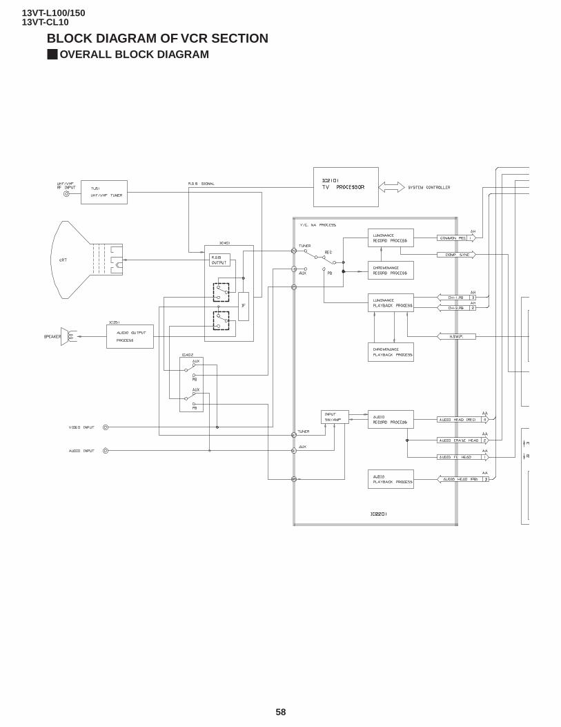
58
13VT-L100/15013VT-CL10
BLOCK DIAGRAM OF VCR SECTIONOVERALL BLOCK DIAGRAM

59
13VT-L100/15013VT-CL10
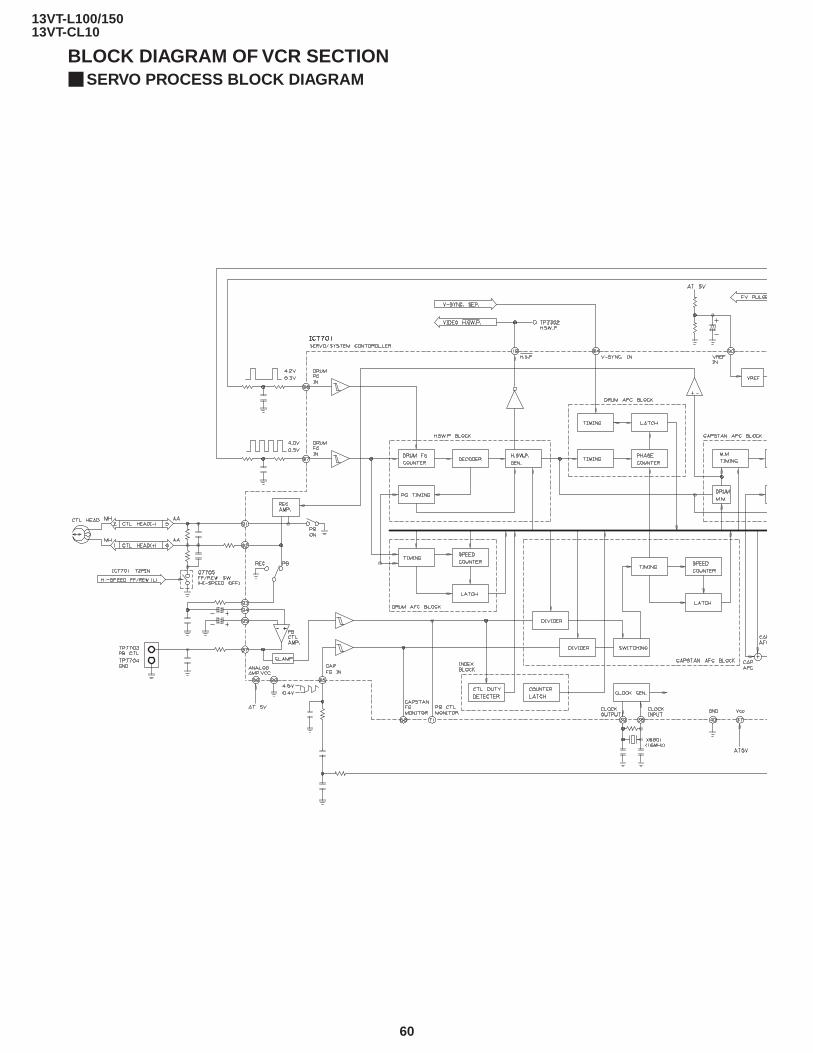
60
13VT-L100/15013VT-CL10
BLOCK DIAGRAM OF VCR SECTIONSERVO PROCESS BLOCK DIAGRAM
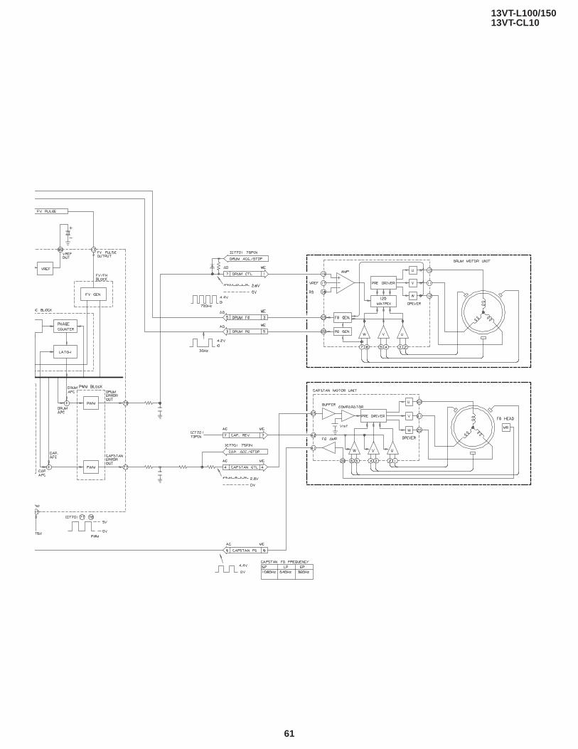
61
13VT-L100/15013VT-CL10
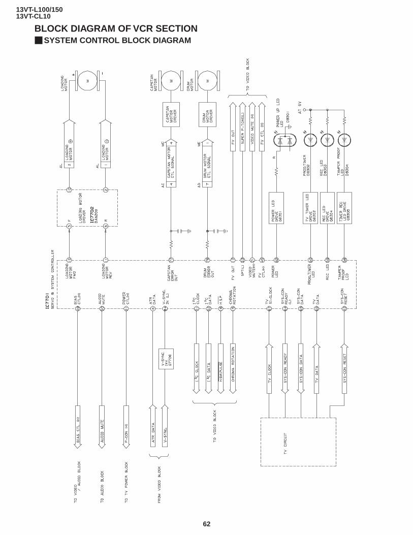
62
13VT-L100/15013VT-CL10
BLOCK DIAGRAM OF VCR SECTIONSYSTEM CONTROL BLOCK DIAGRAM

63
13VT-L100/15013VT-CL10
SAFETY DEVICE BLOCK DIAGRAM
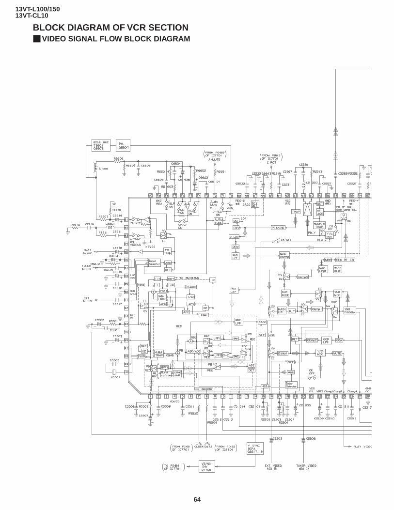
64
13VT-L100/15013VT-CL10
BLOCK DIAGRAM OF VCR SECTIONVIDEO SIGNAL FLOW BLOCK DIAGRAM
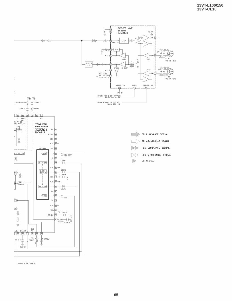
65
13VT-L100/15013VT-CL10

66
13VT-L100/15013VT-CL10
BLOCK DIAGRAM OF VCR SECTIONAUDIO BLOCK DIAGRAM

67
13VT-L100/15013VT-CL10
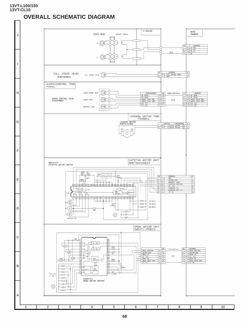
68
13VT-L100/15013VT-CL10
A
B
C
D
E
F
G
H
I
J
1 2 3 4 5 6 7 8 9 10
OVERALL SCHEMATIC DIAGRAM

69
13VT-L100/15013VT-CL10
10 11 12 13 14 15 16 17 18 19

70
13VT-L100/15013VT-CL10
DESCRIPTION OF SECTION SCHEMATIC DIAGRAMNOTE:1. The unit of resistance "ohm" is omitted
(K:1000 ohms, M:1 Meg ohm).2. All resistors are 1/8 watt, unless otherwise noted.3. All capacitors are 50V, unless otherwise noted.4. All capacitors are µF, unless otherwise noted. (P: µµF)5. (G) indicates ±2% tolerance may be used.
VOLTAGE MEASUREMENT CONDITIONS:1. All DC voltages are measured with DVM connected
between points indicated and chassis ground, linevoltage set at 120V AC and all controls set for normalpicture unless otherwise indicated.
2. All voltages measured with 1000µV B&W or Colorsignal.
WAVEFORMS
WAVEFORM MEASUREMENT CONDI-TIONS:1. Photographs taken on a standard gated color bar signal,
the tint setting adjusted for proper color. The wave shapesat the red, green and blue cathodes of the picture tubedepend on the tint, color level and picture control.
2. indicates waveform check points (See chart, waveformsare measured from point indicated to chassis ground.)
å AND SHADED ( ) COMPONENTS= SAFETY RELATED PARTS.
ç MARK= X-RAY RELATED PARTS.
DRGANNES MARQUES åET HACHRES ( ):PIECES RELATIVES A LA SECURITE.MARQUE ç : PIECS RELATIVE AUX RAYONS X.
This circuit diagram is a standard one, printed circuitsmay be subject to change for product improvementwithout prior notice.

71
13VT-L100/15013VT-CL10
A
B
C
D
E
F
G
H
I
J
1 2 3 4 5 6 7 8 9 10
SCHEMATIC DIAGRAM : CRT UNIT

72
13VT-L100/15013VT-CL10
A
B
C
D
E
F
G
H
I
J
1 2 3 4 5 6 7 8 9 10
SCHEMATIC DIAGRAM : MAIN-1 Unit (TV Section)
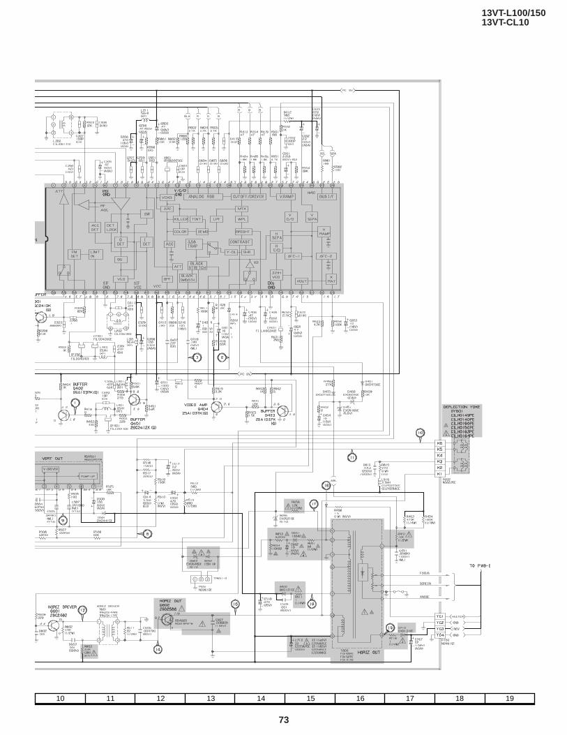
73
13VT-L100/15013VT-CL10
10 11 12 13 14 15 16 17 18 19
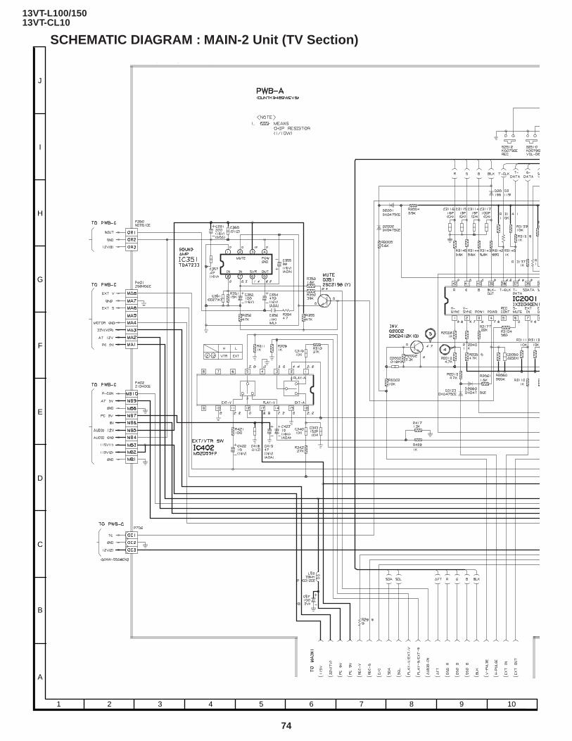
74
13VT-L100/15013VT-CL10
SCHEMATIC DIAGRAM : MAIN-2 Unit (TV Section)
A
B
C
D
E
F
G
H
I
J
1 2 3 4 5 6 7 8 9 10

75
13VT-L100/15013VT-CL10
10 11 12 13 14 15 16 17 18 19

76
13VT-L100/15013VT-CL10
A
B
C
D
E
F
G
H
I
J
1 2 3 4 5 6 7 8 9 10
SCHEMATIC DIAGRAM : POWER Unit (TV Section)

77
13VT-L100/15013VT-CL10
10 11 12 13 14 15 16 17 18 19

78
13VT-L100/15013VT-CL10
A
B
C
D
E
F
G
H
I
J
1 2 3 4 5 6 7 8 9 10
SCHEMATIC DIAGRAM : MAIN Unit (VCR-1 Section)
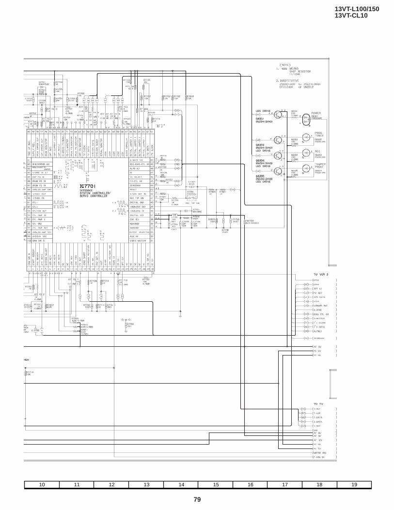
79
13VT-L100/15013VT-CL10
10 11 12 13 14 15 16 17 18 19

80
13VT-L100/15013VT-CL10
A
B
C
D
E
F
G
H
I
J
1 2 3 4 5 6 7 8 9 10
SCHEMATIC DIAGRAM : MAIN Unit (VCR-2 Section)
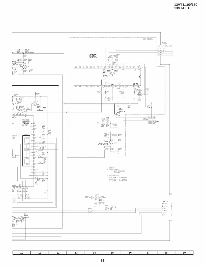
81
13VT-L100/15013VT-CL10
10 11 12 13 14 15 16 17 18 19

82
13VT-L100/15013VT-CL10
A
B
C
D
E
F
G
H
I
J
1 2 3 4 5 6 7 8 9 10
PRINTED WIRING BOARD ASSEMBLIES
PWB-B: CRT Unit (Wiring Side)
PWB-C: POWER Unit (Wiring Side)
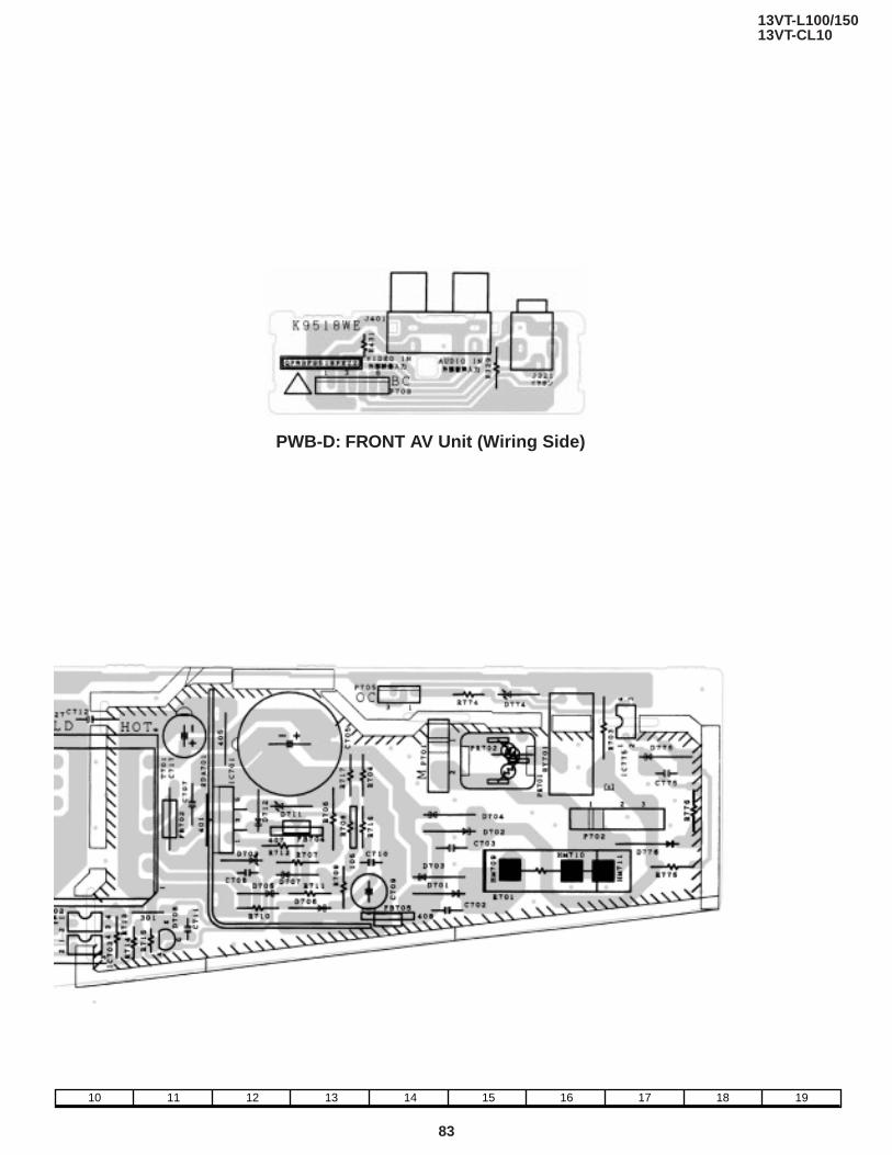
83
13VT-L100/15013VT-CL10
10 11 12 13 14 15 16 17 18 19
PWB-D: FRONT AV Unit (Wiring Side)

84
13VT-L100/15013VT-CL10
A
B
C
D
E
F
G
H
I
J
1 2 3 4 5 6 7 8 9 10
PWB-A: MAIN Unit (Wiring Side)
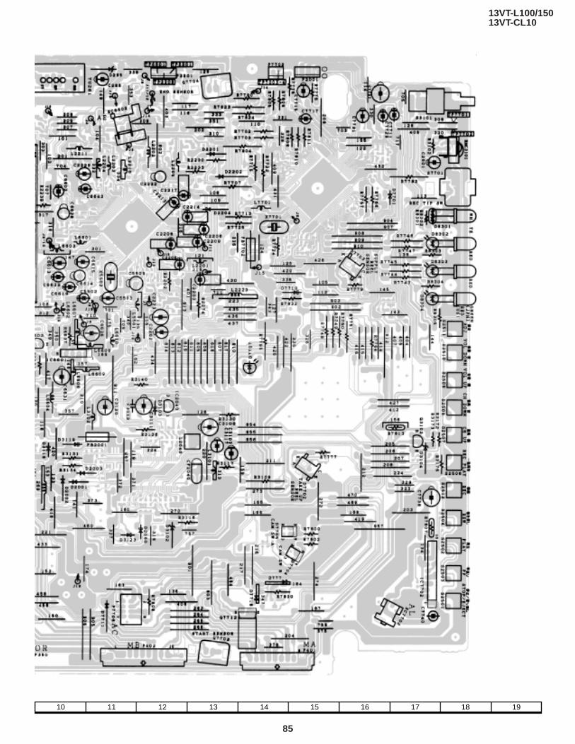
85
13VT-L100/15013VT-CL10
10 11 12 13 14 15 16 17 18 19

86
13VT-L100/15013VT-CL10
A
B
C
D
E
F
G
H
I
J
1 2 3 4 5 6 7 8 9 10
PWB-A: MAIN Unit (Chip Parts Side)

87
13VT-L100/15013VT-CL10
10 11 12 13 14 15 16 17 18 19

88
13VT-L100/15013VT-CL10
- M E M O -

13VT-L100/15013VT-CL10
Ref. No. Part No. ★ Description Code Ref. No. Part No. ★ Description Code
89
Ref. No. Part No. ★ Description Code
PARTS LISTPARTS REPLACEMENT
Replacement parts which have these special safety characteristics iden-tified in this manual ; electrical components having such features are iden-tified by å and shaded areas in the Replacement Parts Lists and Sche-matic Diagrams. The use of a substitute replacement part which dose nohave the same safety characteristic as the factory recommended replace-ment parts shown in this service manual may create shock, fire or otherhazards.
"HOW TO ORDER REPLACEMENT PARTS"To have your order filled promptly and correctly, please furnish the follow-ing informations.
1. MODEL NUMBER 2. REF. NO.
3. PART NO. 4. DESCRIPTION
in USA: Contact your nearest SHARP Parts Distributor to order. Forlocation of SHARP Parts Distributor, Please call Toll-Free; 1-800-BE-SHARP
çå V101 VB34KPU02X/*S J Picture Tube BZçå DY601 RCiLH0149PEN1 R Deflection Yoke BA
å RCiLG0403PEZZ R Degaussing Coil AK
LISTE DES PIECESCHANGE DES PIECES
Les pi`eces de rechange qui pr élelesentent ces caract éleristiques spéleciales de s élecurit éle, sont identifi élees dans ce manuel : les pi`ecesélelectriques qui pr élesentent ces particularit éles, sont rep éler élee parla marque å et sont hachur élees dans les listes de pi`eces et dans lesdiagrammes sch élematiques.La substitution d'une pi`ece de rechange par une autre qui ne pr éLesentepas les m éoemes caract éLeristiques de s élecurit éle que la pi`ecerecommand élee parl'usine et dans ce manuel de service, peut provoquerune éLelectrocution, un incendie ou toutautre sinistre.
"COMMENT COMMANDER LES PIECES DE RECHANGE"Pour que votre commande soit rapidement et correctement remplie,veuillez fournir les renseignements suivants.
1. NUMERO DU MODELE 2. NO. DE REF
3. NO. DE PIECE 4. DESCRIPTION
in CANADA : Contact SHARP Electronics of Canada LimitedPhone (416) 890-2100
★ MARK: SPARE PARTS-DELIVERY SECTION
▲ MARK: X-RAY RELATED PARTS
Ref. No. Part No. ★ Description Code
PWB-A: DUNTK9489WEV8MAIN Unit
★ MARQUE: SECTION LIVRAISON DES PIECES DERECHANGE
▲ MARQUE: PIECES RELATIVE AUX RAYONS X
PICTURE TUBE
TUNER
å TU51 VTUATELH9225A J Vhf Tuner BF
INTEGRATED CIRCUITSIC351 VHiTDA7233/-1 J TDA7233 AFIC401 RH-iX3253CEZZ J IX3253CE AV
å IC402 VHiM52055FP-1 J M52055FP AHå IC501 VHiLA7830//-1 J LA7830 AH
IC2001 RH-iX3204CEZZ J IX3204CE AYIC2040 VHiPST994C/-1 J PST994C ADIC2101 VHiBR2401E2-1 J BR24C01E2 AFIC2201 VHiNN3472F/-1 J NN3472F AXIC3301 VHiAN3363S/-1 J AN3363S AHIC6601 VHiBA7755//-1 J BA7755 ADIC7701 RH-iX3056CEZZ J IX3056CE AZIC7702 VHiBA6209//1E J BA6209 AG
TRANSISTORSQ201 VS2SC1906//1E J 2SC1906 ACQ301 VS2SC2412KQ-1 J 2SC2412KQ AAQ351 VS2SC3198-Y-1 J 2SC3198-Y AAQ401 VS2SC2412KQ-1 J 2SC2412KQ AAQ402 VS2SA1037KQ-1 J 2SA1037KQ AAQ403 VS2SC2412KQ-1 J 2SC2412KQ AAQ404 VS2SA1037KQ-1 J 2SA1037KQ AAQ433 VS2SA1037KQ-1 J 2SA1037KQ AAQ601 VS2SC2482//-1 J 2SC2482 AD
å Q602 VS2SD2586//1E J 2SD2586 AMQ2002 VS2SC2412KQ-1 J 2SC2412KQ AAQ2206 VS2SA1037KQ-1 J 2SA1037KQ AAQ2207 VS2SA1037KQ-1 J 2SA1037KQ AAQ2208 VS2SC2412KQ-1 J 2SC2412KQ AAQ2209 VS2SC2412KQ-1 J 2SC2412KQ AAQ2210 VS2SC2412KQ-1 J 2SC2412KQ AAQ2215 VS2SC2412KQ-1 J 2SC2412KQ AAQ2217 VS2SC2412KQ-1 J 2SC2412KQ AAQ2218 VSUN2113///-1 J UN2113 AAQ2219 VSUN2213///-1 J UN2213 AAQ2220 VS2SA1037KQ-1 J 2SA1037KQ AAQ2224 VSUN2113///-1 J UN2113 AA
NOTE: THE PARTS HERES SHOWN ARE SUPPLIED AS AN ASSEM-BLY NOT INDEPENEDENTLY.
PRINTED WIRING BOARD ASSEMBLYS(NOT REPLACEMENT ITEM)
PWB-A DUNTK9489WEV8 – Main Unit —PWB-B DUNTK8606WEW4 – CRT Unit —PWB-C DUNTK9490WEV8 – Power Unit —
(13VT-L100/L150)PWB-C DUNTK9490WEW1 – Power Unit —
(13VT-CL10)PWB-D DUNTK9518WEV2 – Front AV Unit —
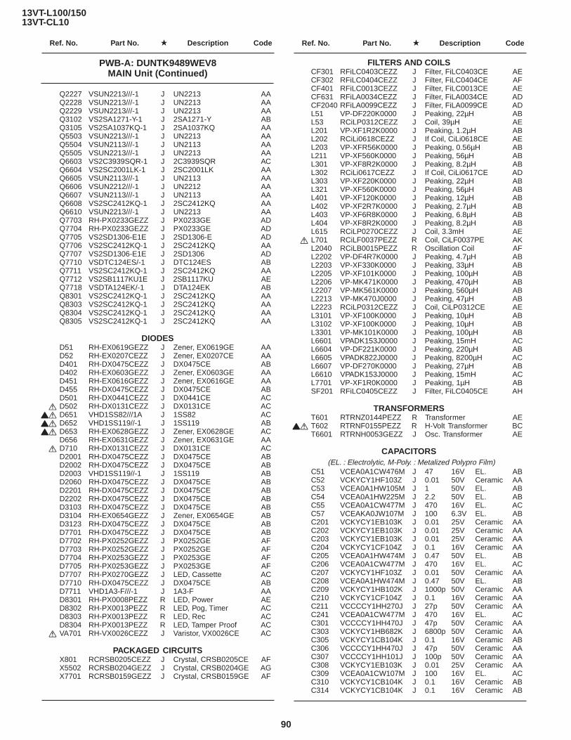
13VT-L100/15013VT-CL10
Ref. No. Part No. ★ Description Code Ref. No. Part No. ★ Description Code
90
Q2227 VSUN2213///-1 J UN2213 AAQ2228 VSUN2213///-1 J UN2213 AAQ2229 VSUN2213///-1 J UN2213 AAQ3102 VS2SA1271-Y-1 J 2SA1271-Y ABQ3105 VS2SA1037KQ-1 J 2SA1037KQ AAQ5503 VSUN2213///-1 J UN2213 AAQ5504 VSUN2113///-1 J UN2113 AAQ5505 VSUN2213///-1 J UN2213 AAQ6603 VS2C3939SQR-1 J 2C3939SQR ACQ6604 VS2SC2001LK-1 J 2SC2001LK AAQ6605 VSUN2113///-1 J UN2113 AAQ6606 VSUN2212///-1 J UN2212 AAQ6607 VSUN2113///-1 J UN2113 AAQ6608 VS2SC2412KQ-1 J 2SC2412KQ AAQ6610 VSUN2213///-1 J UN2213 AAQ7703 RH-PX0233GEZZ J PX0233GE ADQ7704 RH-PX0233GEZZ J PX0233GE ADQ7705 VS2SD1306-E1E J 2SD1306-E ADQ7706 VS2SC2412KQ-1 J 2SC2412KQ AAQ7707 VS2SD1306-E1E J 2SD1306 ADQ7710 VSDTC124ES/-1 J DTC124ES ABQ7711 VS2SC2412KQ-1 J 2SC2412KQ AAQ7712 VS2SB1117KU1E J 2SB1117KU AEQ7718 VSDTA124EK/-1 J DTA124EK ABQ8301 VS2SC2412KQ-1 J 2SC2412KQ AAQ8303 VS2SC2412KQ-1 J 2SC2412KQ AAQ8304 VS2SC2412KQ-1 J 2SC2412KQ AAQ8305 VS2SC2412KQ-1 J 2SC2412KQ AA
DIODESD51 RH-EX0619GEZZ J Zener, EX0619GE AAD52 RH-EX0207CEZZ J Zener, EX0207CE AAD401 RH-DX0475CEZZ J DX0475CE ABD402 RH-EX0603GEZZ J Zener, EX0603GE AAD451 RH-EX0616GEZZ J Zener, EX0616GE AAD455 RH-DX0475CEZZ J DX0475CE ABD501 RH-DX0441CEZZ J DX0441CE AC
å D502 RH-DX0131CEZZ J DX0131CE ACçå D651 VHD1SS82///1A J 1SS82 ACçå D652 VHD1SS119//-1 J 1SS119 ABçå D653 RH-EX0628GEZZ J Zener, EX0628GE AC
D656 RH-EX0631GEZZ J Zener, EX0631GE AAå D710 RH-DX0131CEZZ J DX0131CE AC
D2001 RH-DX0475CEZZ J DX0475CE ABD2002 RH-DX0475CEZZ J DX0475CE ABD2003 VHD1SS119//-1 J 1SS119 ABD2060 RH-DX0475CEZZ J DX0475CE ABD2201 RH-DX0475CEZZ J DX0475CE ABD2202 RH-DX0475CEZZ J DX0475CE ABD3103 RH-DX0475CEZZ J DX0475CE ABD3104 RH-EX0654GEZZ J Zener, EX0654GE ABD3123 RH-DX0475CEZZ J DX0475CE ABD7701 RH-DX0475CEZZ J DX0475CE ABD7702 RH-PX0252GEZZ J PX0252GE AFD7703 RH-PX0252GEZZ J PX0252GE AFD7704 RH-PX0253GEZZ J PX0253GE AFD7705 RH-PX0253GEZZ J PX0253GE AFD7707 RH-PX0270GEZZ J LED, Cassette ACD7710 RH-DX0475CEZZ J DX0475CE ABD7711 VHD1A3-F///-1 J 1A3-F AAD8301 RH-PX0008PEZZ R LED, Power AED8302 RH-PX0013PEZZ R LED, Pog, Timer ACD8303 RH-PX0013PEZZ R LED, Rec ACD8304 RH-PX0013PEZZ R LED, Tamper Proof AC
å VA701 RH-VX0026CEZZ J Varistor, VX0026CE AC
PACKAGED CIRCUITSX801 RCRSB0205CEZZ J Crystal, CRSB0205CE AFX5502 RCRSB0204GEZZ J Crystal, CRSB0204GE AGX7701 RCRSB0159GEZZ J Crystal, CRSB0159GE AF
FILTERS AND COILSCF301 RFiLC0403CEZZ J Filter, FiLC0403CE AECF302 RFiLC0404CEZZ J Filter, FiLC0404CE AFCF401 RFiLC0013CEZZ J Filter, FiLC0013CE AECF631 RFiLA0034CEZZ J Filter, FiLA0034CE ADCF2040 RFiLA0099CEZZ J Filter, FiLA0099CE ADL51 VP-DF220K0000 J Peaking, 22µH ABL53 RCiLP0312CEZZ J Coil, 39µH AEL201 VP-XF1R2K0000 J Peaking, 1.2µH ABL202 RCiLi0618CEZZ J If Coil, CiLi0618CE AEL203 VP-XFR56K0000 J Peaking, 0.56µH ABL211 VP-XF560K0000 J Peaking, 56µH ABL301 VP-XF8R2K0000 J Peaking, 8.2µH ABL302 RCiLi0617CEZZ J If Coil, CiLi0617CE ADL303 VP-XF220K0000 J Peaking, 22µH ABL321 VP-XF560K0000 J Peaking, 56µH ABL401 VP-XF120K0000 J Peaking, 12µH ABL402 VP-XF2R7K0000 J Peaking, 2.7µH ABL403 VP-XF6R8K0000 J Peaking, 6.8µH ABL404 VP-XF8R2K0000 J Peaking, 8.2µH ABL615 RCiLP0270CEZZ J Coil, 3.3mH AE
å L701 RCiLF0037PEZZ R Coil, CiLF0037PE AKL2040 RCiLB0015PEZZ R Oscillation Coil AFL2202 VP-DF4R7K0000 J Peaking, 4.7µH ABL2203 VP-XF330K0000 J Peaking, 33µH ABL2205 VP-XF101K0000 J Peaking, 100µH ABL2206 VP-MK471K0000 J Peaking, 470µH ABL2207 VP-MK561K0000 J Peaking, 560µH ABL2213 VP-MK470J0000 J Peaking, 47µH ABL2223 RCiLP0312CEZZ J Coil, CiLP0312CE AEL3101 VP-XF100K0000 J Peaking, 10µH ABL3102 VP-XF100K0000 J Peaking, 10µH ABL3301 VP-MK101K0000 J Peaking, 100µH ABL6601 VPADK153J0000 J Peaking, 15mH ACL6604 VP-DF221K0000 J Peaking, 220µH ABL6605 VPADK822J0000 J Peaking, 8200µH ACL6607 VP-DF270K0000 J Peaking, 27µH ABL6610 VPADK153J0000 J Peaking, 15mH ACL7701 VP-XF1R0K0000 J Peaking, 1µH ABSF201 RFiLC0405CEZZ J Filter, FiLC0405CE AH
TRANSFORMERST601 RTRNZ0144PEZZ R Transformer AE
çå T602 RTRNF0155PEZZ R H-Volt Transformer BCT6601 RTRNH0053GEZZ J Osc. Transformer AE
CAPACITORS (EL. : Electrolytic, M-Poly. : Metalized Polypro Film)
C51 VCEA0A1CW476M J 47 16V EL. ABC52 VCKYCY1HF103Z J 0.01 50V Ceramic AAC53 VCEA0A1HW105M J 1 50V EL. ABC54 VCEA0A1HW225M J 2.2 50V EL. ABC55 VCEA0A1CW477M J 470 16V EL. ACC57 VCEAKA0JW107M J 100 6.3V EL. ABC201 VCKYCY1EB103K J 0.01 25V Ceramic AAC202 VCKYCY1EB103K J 0.01 25V Ceramic AAC203 VCKYCY1EB103K J 0.01 25V Ceramic AAC204 VCKYCY1CF104Z J 0.1 16V Ceramic AAC205 VCEA0A1HW474M J 0.47 50V EL. ABC206 VCEA0A1CW477M J 470 16V EL. ACC207 VCKYCY1HF103Z J 0.01 50V Ceramic AAC208 VCEA0A1HW474M J 0.47 50V EL. ABC209 VCKYCY1HB102K J 1000p 50V Ceramic AAC210 VCKYCY1CF104Z J 0.1 16V Ceramic AAC211 VCCCCY1HH270J J 27p 50V Ceramic AAC241 VCEA0A1CW477M J 470 16V EL. ACC301 VCCCCY1HH470J J 47p 50V Ceramic AAC303 VCKYCY1HB682K J 6800p 50V Ceramic AAC305 VCKYCY1CB104K J 0.1 16V Ceramic ABC306 VCCCCY1HH470J J 47p 50V Ceramic AAC307 VCCCCY1HH101J J 100p 50V Ceramic AAC308 VCKYCY1EB103K J 0.01 25V Ceramic AAC309 VCEA0A1CW107M J 100 16V EL. ACC310 VCKYCY1CB104K J 0.1 16V Ceramic ABC314 VCKYCY1CB104K J 0.1 16V Ceramic AB
PWB-A: DUNTK9489WEV8MAIN Unit (Continued)

13VT-L100/15013VT-CL10
Ref. No. Part No. ★ Description Code Ref. No. Part No. ★ Description Code
91
PWB-A: DUNTK9489WEV8MAIN Unit (Continued)
C329 VCKYCY1EB103K J 0.01 25V Ceramic AAC340 VCKYCY1CB104K J 0.1 16V Ceramic ABC341 VCE9EA1HW105M J 1 50V EL.(N.P) ACC343 VCCCCY1HH151J J 150p 50V Ceramic AAC351 VCKYCY1HB272K J 2700p 50V Ceramic AAC352 VCEAEA1CW107M J 100 16V EL. ACC354 VCEA0A1CW477M J 470 16V EL. ACC355 VCEA0A1CW226M J 22 16V EL. ABC356 VCQYTA1HM104K J 0.1 50V Mylar ACC357 VCKYCY1CF474Z J 0.47 16V Ceramic ABC360 VCKYCY1HF103Z J 0.01 50V Ceramic AAC361 VCEA0A1CW337M J 330 16V EL. ACC401 VCCCCY1HH271J J 270p 50V Ceramic AAC402 VCCCCY1HH470J J 47p 50V Ceramic AAC403 VCCCCY1HH100D J 10p 50V Ceramic AAC405 VCEA0A1HW105M J 1 50V EL. ABC406 VCEA0A1HW474M J 0.47 50V EL. ABC408 VCEA0A1CW106M J 10 16V EL. ABC409 VCEA0A1HW105M J 1 50V EL. ABC410 VCQYTA1HM104K J 0.1 50V Mylar ACC411 VCEA0A1CW108M J 1000 16V EL. ADC412 VCKYCY1CB104K J 0.1 16V Ceramic ABC413 VCKYCY1HF103Z J 0.01 50V Ceramic AAC414 VCE9EA1HW105M J 1 50V EL.(N.P) ACC418 VCKYCY1HF103Z J 0.01 50V Ceramic AAC419 VCEA0A1CW476M J 47 16V EL. ABC420 VCE9EA1HW105M J 1 50V EL.(N.P) ACC422 VCEAKM1CW106M J 10 16V EL. ABC423 VCEA0A1CW106M J 10 16V EL. ABC451 VCQYTA2AA563K J 0.056 100V Mylar ABC454 VCEA0A1CW106M J 10 16V EL. ABC502 VCEA0A1VW477M J 470 35V EL. ABC504 VCKYPA2HB561K J 560p 500V Ceramic AAC505 VCQYTA1HM473K J 0.047 50V Mylar ABC507 VCQYTA1HM152K J 1500p 50V Mylar ABC508 VCEA0A1HW107M J 100 50V EL. ABC509 VCKYPA2HB102K J 1000p 500V Ceramic AAC510 VCEA0A1VW477M J 470 35V EL. ABC513 VCEA0A1HW225M J 2.2 50V EL. ABC514 VCEACA1HC335J J 3.3 50V EL. ACC551 VCEACA1HC225J J 2.2 50V EL. ACC552 VCEA0A1HW225M J 2.2 50V EL. ABC553 VCCCCY1HH391J J 390p 50V Ceramic AAC602 VCKYPA1HB102K J 1000p 50V Ceramic AAC603 VCKYPA2HB102K J 1000p 500V Ceramic AAC606 VCKYPA1HB472K J 4700p 50V Ceramic AA
çåC607 VCFPPD3CA682H J 6800p 1600V M-Poly AEC612 VCFPVC2DB474J J 0.47 200V M-Poly AEC631 VCEA0A1HW475M J 4.7 50V EL. ABC632 VCKYCY1EB103K J 0.01 25V Ceramic AAC633 VCEA0A1CW477M J 470 16V EL. AC
çå C652 VCEA0A1HW106M J 10 50V EL. ABC653 VCEA0A1CW106M J 10 16V EL. AB
å C701 RC-FZ021SCEZZ J 0.22 AC250 V AEå C713 RC-EZ0587CEZZ J 33 200V EL. AF
C767 VCEA0A2AW226M J 22 100V EL. ACC801 VCKYCY1EB223K J 0.022 25V Ceramic AAC802 VCEA0A1HW474M J 0.47 50V EL. ABC803 VCCCCY1HH120J J 12p 50V Ceramic AAC804 VCKYCY1EB103K J 0.01 25V Ceramic AAC805 VCKYCY1EB103K J 0.01 25V Ceramic AAC806 VCKYCY1EB103K J 0.01 25V Ceramic AAC807 VCCCPA1HH270J J 27p 50V Ceramic AAC2002 VCKYCY1EB183K J 0.018 25V Ceramic AAC2041 VCKYCY1CB104K J 0.1 16V Ceramic ABC2060 VCKYCY1EB223K J 0.022 25V Ceramic AAC2201 VCKYCY1EB822K J 8200p 25V Ceramic AAC2202 VCEAKA1HW225M J 2.2 50V EL. ABC2203 VCEA9A0JW226M J 22 6.3V EL. ABC2204 VCKYCY1HF103Z J 0.01 50V Ceramic AAC2205 VCEA9A1CW106M J 10 16V EL. ABC2206 VCE9EA1HW225M J 2.2 50V EL.(N.P) AB
C2207 VCKYCY1HF103Z J 0.01 50V Ceramic AAC2208 VCEA9A0JW476M J 47 6.3V EL. ABC2209 VCEA9A0JW476M J 47 6.3V EL. ABC2210 VCKYCY1HF103Z J 0.01 50V Ceramic AAC2211 VCKYCY1CF104Z J 0.1 16V Ceramic AAC2212 VCKYCY1CF104Z J 0.1 16V Ceramic AAC2213 VCEAEA1EW475M J 4.7 25V EL. ABC2214 VCEA9A1CW106M J 10 16V EL. ABC2215 VCCCCY1HH221J J 220p 50V Ceramic AAC2216 VCKYCY1CF474Z J 0.47 16V Ceramic ABC2217 VCEA9A1HW474M J 0.47 50V EL. ABC2218 VCKYCY1HF103Z J 0.01 50V Ceramic AAC2219 VCCCCY1HH330J J 33p 50V Ceramic AAC2220 VCKYCY1HF103Z J 0.01 50V Ceramic AAC2221 VCKYCY1CF104Z J 0.1 16V Ceramic AAC2222 VCEA9M1CW106M J 10 16V EL. ABC2223 VCEAKM0JW107M J 100 6.3V EL. ABC2225 VCCCCY1HH390J J 39p 50V Ceramic AAC2227 VCKYCY1AF105Z J 1.0 10V Ceramic ACC2228 VCCCCY1HH820J J 82p 50V Ceramic AAC2229 VCEA9A0JW476M J 47 6.3V EL. ABC2230 VCKYCY1HF103Z J 0.01 50V Ceramic AAC2231 VCKYCY1HF103Z J 0.01 50V Ceramic AAC2233 VCKYCY1CF104Z J 0.1 16V Ceramic AAC2237 VCCCCY1HH201J J 200p 50V Ceramic ADC2238 VCKYCY1HF103Z J 0.01 50V Ceramic AAC2239 VCKYCY1CF474Z J 0.47 16V Ceramic ABC2244 VCKYCY1HF223Z J 0.022 50V Ceramic ABC2245 VCKYCY1CF104Z J 0.1 16V Ceramic AAC2247 VCEAKM1CW476M J 47 16V EL. ABC2254 VCKYCY1HF103Z J 0.01 50V Ceramic AAC2258 VCKYCY1EB103K J 0.01 25V Ceramic AAC2259 VCKYCY1EB103K J 0.01 25V Ceramic AAC2260 VCKYCY1EB103K J 0.01 25V Ceramic AAC2267 VCKYCY1HF103Z J 0.01 50V Ceramic AAC2269 VCKYCY1HF103Z J 0.01 50V Ceramic AAC2271 VCCCPA1HH270J J 27p 50V Ceramic AAC2273 RC-KZ0019GEZZ J 0.1 25V Ceramic AAC2601 VCEA0A1AW476M J 47 10V EL. ABC3102 VCCCCY1HH221J J 220p 50V Ceramic AAC3103 VCEAKA1HW105M J 1 50V EL. ABC3104 VCKYCY1HB102K J 1000p 50V Ceramic AAC3105 VCCCCY1HH221J J 220p 50V Ceramic AAC3107 VCKYCY1HF103Z J 0.01 50V Ceramic AAC3108 VCEAKA0JW107M J 100 6.3V EL. ABC3109 VCKYCY1CB104K J 0.1 16V Ceramic ABC3110 VCKYCY1HB222K J 2200p 50V Ceramic AAC3111 VCEA9A0JW107M J 100 6.3V EL. ABC3112 VCKYPA1HF103Z J 0.01 50V Ceramic AAC3113 VCCCCY1HH101J J 100p 50V Ceramic AAC3114 VCCCCY1HH150J J 15p 50V Ceramic AAC3115 VCCCCY1HH150J J 15p 50V Ceramic AAC3116 VCCCCY1HH150J J 15p 50V Ceramic AAC3117 VCEAKA1CW106M J 10 16V EL. ABC3130 VCKYCY1HF103Z J 0.01 50V Ceramic AAC3301 VCKYCY1HF223Z J 0.022 50V Ceramic ABC3302 VCCCCY1HH220J J 22p 50V Ceramic AAC3303 VCKYCY1HF223Z J 0.022 50V Ceramic ABC3304 VCCCCY1HH220J J 22p 50V Ceramic AAC3311 VCKYCY1HB471K J 470p 50V Ceramic AAC3312 VCKYCY1HF103Z J 0.01 50V Ceramic AAC3313 VCKYCY1CF104Z J 0.1 16V Ceramic AAC3314 VCKYCY1CF104Z J 0.1 16V Ceramic AAC3316 VCKYCY1CF104Z J 0.1 16V Ceramic AAC3317 VCEAKM1CW476M J 47 16V EL. ABC5501 VCKYCY1HB392K J 3900p 50V Ceramic AAC5502 VCEA9A1HW225M J 2.2 50V EL. ABC5503 VCEA9A1HW225M J 2.2 50V EL. ABC5505 VCKYCY1HF103Z J 0.01 50V Ceramic AAC5506 VCKYCY1HF103Z J 0.01 50V Ceramic AAC5507 VCKYCY1CF474Z J 0.47 16V Ceramic ABC5508 VCKYCY1CF104Z J 0.1 16V Ceramic AAC5509 VCEA9M0JW476M J 47 6.3V EL. ABC5510 VCKYCY1HF103Z J 0.01 50V Ceramic AAC5511 VCKYCY1HF103Z J 0.01 50V Ceramic AAC5512 VCKYCY1EB223K J 0.022 25V Ceramic AA
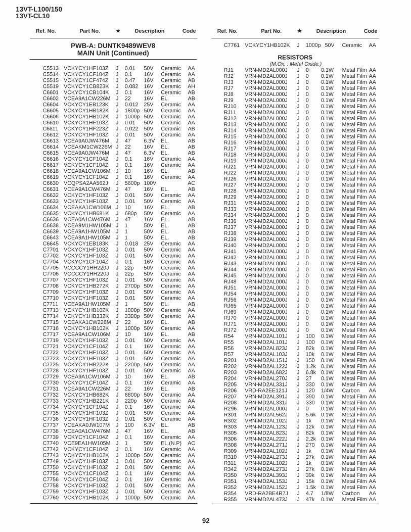
13VT-L100/15013VT-CL10
Ref. No. Part No. ★ Description Code Ref. No. Part No. ★ Description Code
92
C5513 VCKYCY1HF103Z J 0.01 50V Ceramic AAC5514 VCKYCY1CF104Z J 0.1 16V Ceramic AAC5515 VCKYCY1CF474Z J 0.47 16V Ceramic ABC5519 VCKYCY1CB823K J 0.082 16V Ceramic AHC6601 VCKYCY1CB104K J 0.1 16V Ceramic ABC6602 VCEA9A1CW226M J 22 16V EL. ABC6604 VCKYCY1EB123K J 0.012 25V Ceramic AAC6605 VCKYCY1HB182K J 1800p 50V Ceramic AAC6606 VCKYCY1HB102K J 1000p 50V Ceramic AAC6610 VCKYCY1HF103Z J 0.01 50V Ceramic AAC6611 VCKYCY1HF223Z J 0.022 50V Ceramic ABC6612 VCKYCY1HF103Z J 0.01 50V Ceramic AAC6613 VCEA9A0JW476M J 47 6.3V EL. ABC6614 VCEAKM1CW226M J 22 16V EL. ABC6615 VCEA9A0JW476M J 47 6.3V EL. ABC6616 VCKYCY1CF104Z J 0.1 16V Ceramic AAC6617 VCKYCY1CF104Z J 0.1 16V Ceramic AAC6618 VCEA9A1CW106M J 10 16V EL. ABC6619 VCKYCY1CF104Z J 0.1 16V Ceramic AAC6630 VCQPSA2AA562J J 5600p 100V ACC6631 VCEA9A1CW476M J 47 16V EL. ABC6632 VCKYCY1HF103Z J 0.01 50V Ceramic AAC6633 VCKYCY1HF103Z J 0.01 50V Ceramic AAC6634 VCEAKA1CW106M J 10 16V EL. ABC6635 VCKYCY1HB681K J 680p 50V Ceramic AAC6636 VCEA0A1CW476M J 47 16V EL. ABC6638 VCEA9M1HW105M J 1 50V EL. ABC6639 VCEA9A1HW105M J 1 50V EL. ABC6643 VCEA9A1HW105M J 1 50V EL. ABC6645 VCKYCY1EB183K J 0.018 25V Ceramic AAC7701 VCKYCY1HF103Z J 0.01 50V Ceramic AAC7702 VCKYCY1HF103Z J 0.01 50V Ceramic AAC7704 VCKYCY1CF104Z J 0.1 16V Ceramic AAC7705 VCCCCY1HH220J J 22p 50V Ceramic AAC7706 VCCCCY1HH220J J 22p 50V Ceramic AAC7707 VCKYCY1HF103Z J 0.01 50V Ceramic AAC7708 VCKYCY1HB272K J 2700p 50V Ceramic AAC7709 VCKYCY1HF103Z J 0.01 50V Ceramic AAC7710 VCKYCY1HF103Z J 0.01 50V Ceramic AAC7711 VCEA9A1HW105M J 1 50V EL. ABC7713 VCKYCY1HB102K J 1000p 50V Ceramic AAC7714 VCKYCY1HB332K J 3300p 50V Ceramic AAC7715 VCEAKA1CW226M J 22 16V EL. ABC7716 VCKYCY1HB102K J 1000p 50V Ceramic AAC7717 VCEA9A1CW106M J 10 16V EL. ABC7719 VCKYCY1HF103Z J 0.01 50V Ceramic AAC7721 VCKYCY1CF104Z J 0.1 16V Ceramic AAC7722 VCKYCY1HF103Z J 0.01 50V Ceramic AAC7723 VCKYCY1HF103Z J 0.01 50V Ceramic AAC7725 VCKYCY1HB222K J 2200p 50V Ceramic AAC7728 VCKYCY1HF103Z J 0.01 50V Ceramic AAC7729 VCEA9A1CW106M J 10 16V EL. ABC7730 VCKYCY1CF104Z J 0.1 16V Ceramic AAC7731 VCEA9A1CW226M J 22 16V EL. ABC7732 VCKYCY1HB682K J 6800p 50V Ceramic AAC7733 VCKYCY1HB221K J 220p 50V Ceramic AAC7734 VCKYCY1CF104Z J 0.1 16V Ceramic AAC7735 VCKYCY1HF103Z J 0.01 50V Ceramic AAC7736 VCKYCY1HF103Z J 0.01 50V Ceramic AAC7737 VCEAKA0JW107M J 100 6.3V EL. ABC7738 VCEA0A1CW476M J 47 16V EL. ABC7739 VCKYCY1CF104Z J 0.1 16V Ceramic AAC7740 VCE9EA1HW105M J 1 50V EL.(N.P) ACC7742 VCKYCY1CF104Z J 0.1 16V Ceramic AAC7743 VCKYCY1HB102K J 1000p 50V Ceramic AAC7749 VCKYCY1HF103Z J 0.01 50V Ceramic AAC7750 VCKYCY1HF103Z J 0.01 50V Ceramic AAC7755 VCKYCY1CF104Z J 0.1 16V Ceramic AAC7756 VCKYCY1CF104Z J 0.1 16V Ceramic AAC7758 VCKYCY1HF103Z J 0.01 50V Ceramic AAC7759 VCKYCY1HF103Z J 0.01 50V Ceramic AAC7760 VCKYCY1HB102K J 1000p 50V Ceramic AA
C7761 VCKYCY1HB102K J 1000p 50V Ceramic AA
RESISTORS (M.Ox. : Metal Oxide.)
RJ1 VRN-MD2AL000J J 0 0.1W Metal Film AARJ2 VRN-MD2AL000J J 0 0.1W Metal Film AARJ3 VRN-MD2AL000J J 0 0.1W Metal Film AARJ7 VRN-MD2AL000J J 0 0.1W Metal Film AARJ8 VRN-MD2AL000J J 0 0.1W Metal Film AARJ9 VRN-MD2AL000J J 0 0.1W Metal Film AARJ10 VRN-MD2AL000J J 0 0.1W Metal Film AARJ11 VRN-MD2AL000J J 0 0.1W Metal Film AARJ12 VRN-MD2AL000J J 0 0.1W Metal Film AARJ13 VRN-MD2AL000J J 0 0.1W Metal Film AARJ14 VRN-MD2AL000J J 0 0.1W Metal Film AARJ15 VRN-MD2AL000J J 0 0.1W Metal Film AARJ16 VRN-MD2AL000J J 0 0.1W Metal Film AARJ17 VRN-MD2AL000J J 0 0.1W Metal Film AARJ18 VRN-MD2AL000J J 0 0.1W Metal Film AARJ19 VRN-MD2AL000J J 0 0.1W Metal Film AARJ21 VRN-MD2AL000J J 0 0.1W Metal Film AARJ22 VRN-MD2AL000J J 0 0.1W Metal Film AARJ26 VRN-MD2AL000J J 0 0.1W Metal Film AARJ27 VRN-MD2AL000J J 0 0.1W Metal Film AARJ28 VRN-MD2AL000J J 0 0.1W Metal Film AARJ29 VRN-MD2AL000J J 0 0.1W Metal Film AARJ31 VRN-MD2AL000J J 0 0.1W Metal Film AARJ33 VRN-MD2AL000J J 0 0.1W Metal Film AARJ34 VRN-MD2AL000J J 0 0.1W Metal Film AARJ36 VRN-MD2AL000J J 0 0.1W Metal Film AARJ37 VRN-MD2AL000J J 0 0.1W Metal Film AARJ38 VRN-MD2AL000J J 0 0.1W Metal Film AARJ39 VRN-MD2AL000J J 0 0.1W Metal Film AARJ40 VRN-MD2AL000J J 0 0.1W Metal Film AARJ41 VRN-MD2AL000J J 0 0.1W Metal Film AARJ42 VRN-MD2AL000J J 0 0.1W Metal Film AARJ43 VRN-MD2AL000J J 0 0.1W Metal Film AARJ44 VRN-MD2AL000J J 0 0.1W Metal Film AARJ45 VRN-MD2AL000J J 0 0.1W Metal Film AARJ48 VRN-MD2AL000J J 0 0.1W Metal Film AARJ51 VRN-MD2AL000J J 0 0.1W Metal Film AARJ54 VRN-MD2AL000J J 0 0.1W Metal Film AARJ56 VRN-MD2AL000J J 0 0.1W Metal Film AARJ65 VRN-MD2AL000J J 0 0.1W Metal Film AARJ69 VRN-MD2AL000J J 0 0.1W Metal Film AARJ70 VRN-MD2AL000J J 0 0.1W Metal Film AARJ71 VRN-MD2AL000J J 0 0.1W Metal Film AARJ72 VRN-MD2AL000J J 0 0.1W Metal Film AAR54 VRN-MD2AL101J J 100 0.1W Metal Film AAR55 VRN-MD2AL101J J 100 0.1W Metal Film AAR56 VRN-MD2AL823J J 82k 0.1W Metal Film AAR57 VRN-MD2AL103J J 10k 0.1W Metal Film AAR201 VRN-MD2AL151J J 150 0.1W Metal Film AAR202 VRN-MD2AL122J J 1.2k 0.1W Metal Film AAR203 VRN-MD2AL682J J 6.8k 0.1W Metal Film AAR204 VRN-MD2AL270J J 27 0.1W Metal Film AAR205 VRN-MD2AL331J J 330 0.1W Metal Film AAR206 VRD-RA2EE121J J 120 1/4W Carbon AAR207 VRN-MD2AL391J J 390 0.1W Metal Film AAR208 VRN-MD2AL331J J 330 0.1W Metal Film AAR296 VRN-MD2AL000J J 0 0.1W Metal Film AAR301 VRN-MD2AL562J J 5.6k 0.1W Metal Film AAR302 VRN-MD2AL102J J 1k 0.1W Metal Film AAR303 VRN-MD2AL123J J 12k 0.1W Metal Film AAR305 VRN-MD2AL823J J 82k 0.1W Metal Film AAR306 VRN-MD2AL222J J 2.2k 0.1W Metal Film AAR308 VRN-MD2AL271J J 270 0.1W Metal Film AAR309 VRN-MD2AL102J J 1k 0.1W Metal Film AAR310 VRN-MD2AL273J J 27k 0.1W Metal Film AAR311 VRN-MD2AL102J J 1k 0.1W Metal Film AAR342 VRN-MD2AL273J J 27k 0.1W Metal Film AAR350 VRN-MD2AL393J J 39k 0.1W Metal Film AAR351 VRN-MD2AL153J J 15k 0.1W Metal Film AAR352 VRN-MD2AL152J J 1.5k 0.1W Metal Film AAR354 VRD-RA2BE4R7J J 4.7 1/8W Carbon AAR355 VRN-MD2AL473J J 47k 0.1W Metal Film AA
PWB-A: DUNTK9489WEV8MAIN Unit (Continued)

13VT-L100/15013VT-CL10
Ref. No. Part No. ★ Description Code Ref. No. Part No. ★ Description Code
93
R802 VRN-MD2AL392J J 3.9k 0.1W Metal Film AAR803 VRN-MD2AL272J J 2.7k 0.1W Metal Film AAR804 VRN-MD2AL272J J 2.7k 0.1W Metal Film AAR805 VRN-MD2AL272J J 2.7k 0.1W Metal Film AAR806 VRN-MD2AL333J J 33k 0.1W Metal Film AAR807 VRN-MD2AL000J J 0 0.1W Metal Film AAR809 VRN-MD2AL101J J 100 0.1W Metal Film AAR810 VRS-CY1JF000J J 0 1/16W M.Ox AAR961 VRD-RA2BE101J J 100 1/8W Carbon ABR962 VRD-RA2BE101J J 100 1/8W Carbon ABR2002 VRN-MD2AL332J J 3.3k 0.1W Metal Film AAR2003 VRN-MD2AL103J J 10k 0.1W Metal Film AAR2004 VRN-MD2AL392J J 3.9k 0.1W Metal Film AAR2005 VRN-MD2AL562J J 5.6k 0.1W Metal Film AAR2012 VRN-MD2AL472J J 4.7k 0.1W Metal Film AAR2013 VRN-MD2AL472J J 4.7k 0.1W Metal Film AAR2028 VRN-MD2AL102J J 1.0k 0.1W Metal Film AAR2040 VRN-MD2AL102J J 1.0k 0.1W Metal Film AAR2043 VRN-MD2AL102J J 1.0k 0.1W Metal Film AAR2055 VRN-MD2AL472J J 4.7k 0.1W Metal Film AAR2060 VRN-MD2AL564J J 560k 0.1W Metal Film AAR2061 VRN-MD2AL152J J 1.5k 0.1W Metal Film AAR2201 VRN-MD2AL103J J 10k 0.1W Metal Film AAR2202 VRD-RA2BE103J J 10k 1/8W Carbon AAR2203 VRN-MD2AL474J J 470k 0.1W Metal Film AAR2204 VRS-CY1JF125J J 1.2M 1/16W M.Ox AAR2205 VRN-MD2AL121J J 120 0.1W Metal Film AAR2208 VRN-MD2AL272J J 2.7k 0.1W Metal Film AAR2210 VRN-MD2AL103J J 10k 0.1W Metal Film AAR2211 VRN-MD2AL682J J 6.8k 0.1W Metal Film AAR2212 VRN-MD2AL103J J 10k 0.1W Metal Film AAR2213 VRN-MD2AL471J J 470 0.1W Metal Film AAR2215 VRN-MD2AL472J J 4.7k 0.1W Metal Film AAR2216 VRN-MD2AL562J J 5.6k 0.1W Metal Film AAR2217 VRN-MD2AL103J J 10k 0.1W Metal Film AAR2222 VRN-MD2AL151J J 150 0.1W Metal Film AAR2225 VRN-MD2AL561J J 560 0.1W Metal Film AAR2226 VRN-MD2AL272J J 2.7k 0.1W Metal Film AAR2227 VRN-MD2AL681J J 680 0.1W Metal Film AAR2228 VRN-MD2AL471J J 470 0.1W Metal Film AAR2229 VRN-MD2AL102J J 1k 0.1W Metal Film AAR2230 VRN-RA2BE272J J 2.7k 1/8W Carbon AAR2231 VRN-MD2AL104J J 100k 0.1W Metal Film AAR2232 VRN-MD2AL101J J 100 0.1W Metal Film AAR2233 VRN-RA2BE822J J 8.2k 1/8W Carbon AAR2234 VRN-MD2AL681J J 680 0.1W Metal Film AAR2235 VRN-MD2AL562J J 5.6k 0.1W Metal Film AAR2236 VRN-MD2AL331J J 330 0.1W Metal Film AAR2237 VRN-MD2AL822J J 8.2k 0.1W Metal Film AAR2238 VRN-MD2AL272J J 2.7k 0.1W Metal Film AAR2245 VRN-MD2AL681J J 680 0.1W Metal Film AAR2253 VRN-MD2AL122J J 1.2k 0.1W Metal Film AAR2254 VRN-MD2AL333J J 33k 0.1W Metal Film AAR2255 VRN-MD2AL103J J 10k 0.1W Metal Film AAR2257 VRN-MD2AL101J J 100 0.1W Metal Film AAR2258 VRN-MD2AL000J J 0 0.1W Metal Film AAR2260 VRN-MD2AL103J J 10k 0.1W Metal Film AAR2261 VRN-MD2AL103J J 10k 0.1W Metal Film AAR2262 VRN-MD2AL103J J 10k 0.1W Metal Film AAR2263 VRN-MD2AL103J J 10k 0.1W Metal Film AAR2267 VRN-MD2AL332J J 3.3k 0.1W Metal Film AAR2271 VRN-MD2AL103J J 10k 0.1W Metal Film AAR2274 VRD-RA2BE224J J 220k 1/8W Carbon AAR2275 VRD-RA2BE125J J 1.2M 1/8W Carbon AAR2276 VRN-MD2AL223J J 22k 0.1W Metal Film AAR2277 VRD-RA2BE103J J 10k 1/8W Carbon AAR2278 VRD-RA2BE102J J 1k 1/8W Carbon AAR2279 VRD-RA2BE102J J 1k 1/8W Carbon AAR3102 VRD-RA2BE470J J 47 1/8W Carbon AAR3104 VRN-MD2AL561J J 560 0.1W Metal Film AAR3107 VRN-MD2AL102J J 1k 0.1W Metal Film AAR3108 VRN-MD2AL102J J 1k 0.1W Metal Film AAR3109 VRD-RA2BE152J J 1.5k 1/8W Carbon AAR3110 VRN-MD2AL102J J 1k 0.1W Metal Film AAR3111 VRN-MD2AL103J J 10k 0.1W Metal Film AAR3112 VRN-MD2AL102J J 1k 0.1W Metal Film AA
PWB-A: DUNTK9489WEV8MAIN Unit (Continued)
R356 VRN-MD2AL473J J 47k 0.1W Metal Film AAR401 VRN-MD2AL682J J 6.8k 0.1W Metal Film AAR402 VRN-MD2AL331J J 330 0.1W Metal Film AAR403 VRN-MD2AL331J J 330 0.1W Metal Film AAR404 VRN-MD2AL102J J 1k 0.1W Metal Film AAR405 VRN-MD2AL330J J 33 0.1W Metal Film ABR406 VRN-MD2AL680J J 68 0.1W Metal Film AAR407 VRN-MD2AL102J J 1k 0.1W Metal Film AAR408 VRN-MD2AL471J J 470 0.1W Metal Film AAR409 VRN-MD2AL123J J 12k 0.1W Metal Film AAR410 VRN-MD2AL104J J 100k 0.1W Metal Film AAR411 VRD-RA2BE104J J 100k 1/8W Carbon AAR412 VRD-RA2EE561J J 560 1/4W Carbon AAR413 VRN-MD2AL470J J 47 0.1W Metal Film AAR414 VRN-MD2AL470J J 47 0.1W Metal Film AAR415 VRN-MD2AL470J J 47 0.1W Metal Film AAR416 VRN-MD2AL222J J 2.2k 0.1W Metal Film AAR417 VRN-MD2AL122J J 1.2k 0.1W Metal Film AAR418 VRN-MD2AL000J J 0 0.1W Metal Film AAR421 VRN-MD2AL101J J 100 0.1W Metal Film AAR422 VRN-MD2AL102J J 1k 0.1W Metal Film AAR423 VRN-MD2AL152J J 1.5k 0.1W Metal Film AAR424 VRN-MD2AL182J J 1.8k 0.1W Metal Film AAR425 VRN-MD2AL182J J 1.8k 0.1W Metal Film AAR426 VRN-MD2AL182J J 1.8k 0.1W Metal Film AAR427 VRD-RA2EE101J J 100 1/4W Carbon AAR428 VRD-RA2EE101J J 100 1/4W Carbon AAR429 VRD-RA2EE101J J 100 1/4W Carbon AAR438 VRN-MD2AL822J J 8.2k 0.1W Metal Film AAR441 VRN-MD2AL122J J 1.2k 0.1W Metal Film AAR442 VRN-MD2AL000J J 0 0.1W Metal Film AAR443 VRN-MD2AL102J J 1k 0.1W Metal Film AA
å R451 VRS-SV2HC103J J 10k 1/2W M.Ox AAR452 VRN-MD2AL000J J 0 0.1W Metal Film AAR453 VRD-RA2EE474J J 470k 1/4W Carbon AAR454 VRD-RA2EE184J J 180k 1/4W Carbon AAR456 VRN-MD2AL273J J 27k 0.1W Metal Film AAR466 VRN-VV3AB1R5J J 1.5 1W Metal Film AAR501 VRN-MD2AL101J J 100 0.1W Metal Film AAR504 VRD-RA2BE471J J 470 1/8W Carbon AAR505 VRD-RA2BE101J J 100 1/8W Carbon ABR506 VRD-RA2BE683G J 68k 1/8W Carbon AAR507 VRD-RA2BE104G J 100k 1/8W Carbon AAR508 VRD-RA2BE683J J 68k 1/8W Carbon AAR510 VRN-VV3AB1R0J J 1 1W Metal Film AA
å R511 VRN-GA2EB1R0J J 1 1/4W Metal Film AAR512 VRD-RM2HD561J J 560 1/2W Carbon AAR516 VRD-RA2BE153G J 15k 1/8W Carbon AAR517 VRD-RA2BE223G J 22k 1/8W Carbon AAR518 VRD-RA2BE154J J 150k 1/8W Carbon AAR519 VRD-RM2HD681J J 680 1/2W Carbon AAR525 VRN-MD2AL183J J 18k 0.1W Metal Film AAR551 VRN-MD2AL472J J 4.7k 0.1W Metal Film AAR552 VRN-MD2AL102J J 1k 0.1W Metal Film AAR554 VRN-MD2AL393J J 39k 0.1W Metal Film AAR601 VRN-MD2AL331J J 330 0.1W Metal Film AAR602 VRD-RM2HD392J J 3.9k 1/2W Carbon AA
å R603 VRS-KT3LB222J J 2.2k 3.0W M.Ox ACR608 VRD-RA2BE331J J 330 1/8W Carbon AAR611 VRD-RM2HD220J J 22 1/2W Carbon AAR615 VRS-VV3AB271J J 270 1W M.Ox AAR631 VRN-MD2AL391J J 390 0.1W Metal Film AAR632 VRD-RA2BE272J J 2.7k 1/8W Carbon AAR633 VRN-MD2AL472J J 4.7k 0.1W Metal Film AA
çå R651 VRD-RM2HD680J J 68 1/2W Carbon AAçå R653 VRD-RA2BE822G J 8.2k 1/8W Carbon AAçå R654 VRD-RA2BE103G J 10k 1/8W Carbon AA
R655 VRN-MD2AL104J J 100k 0.1W Metal Film AAå R656 VRD-RM2HD123J J 12k 1/2W Carbon AAå R702 VRC-UA2HG395K J 3.9M 1/2W Solid AAå R718 VRN-GA2EB1R0J J 1 1/4W Metal Film AA
R801 VRN-MD2AL103J J 10k 0.1W Metal Film AA

13VT-L100/15013VT-CL10
Ref. No. Part No. ★ Description Code Ref. No. Part No. ★ Description Code
94
R3113 VRN-MD2AL103J J 10k 0.1W Metal Film AAR3117 VRD-RA2BE102J J 1k 1/8W Carbon AAR3118 VRN-MD2AL122J J 1.2k 0.1W Metal Film AAR3119 VRS-CY1JF105J J 1M 1/16W M.Ox AAR3120 VRN-MD2AL222J J 2.2k 0.1W Metal Film AAR3121 VRN-MD2AL223J J 22k 0.1W Metal Film AAR3122 VRN-MD2AL102J J 1k 0.1W Metal Film AAR3123 VRN-MD2AL223J J 22k 0.1W Metal Film AAR3124 VRN-MD2AL102J J 1k 0.1W Metal Film AAR3125 VRN-MD2AL223J J 22k 0.1W Metal Film AAR3127 VRN-MD2AL334J J 330k 0.1W Metal Film ACR3128 VRN-MD2AL564J J 560k 0.1W Metal Film AAR3129 VRN-MD2AL102J J 1k 0.1W Metal Film AAR3130 VRD-RA2BE223J J 22k 1/8W Carbon AAR3131 VRD-RA2BE221J J 220 1/8W Carbon AAR3132 VRN-MD2AL103J J 10k 0.1W Metal Film AAR3133 VRN-MD2AL221J J 220 0.1W Metal Film AAR3134 VRD-RA2BE221J J 220 1/8W Carbon AAR3135 VRN-MD2AL103J J 10k 0.1W Metal Film AAR3136 VRD-RA2BE102J J 1k 1/8W Carbon AAR3137 VRN-MD2AL102J J 1k 0.1W Metal Film AAR3138 VRN-MD2AL102J J 1k 0.1W Metal Film AAR3139 VRN-MD2AL103J J 10k 0.1W Metal Film AAR3140 VRD-RA2BE102J J 1k 1/8W Carbon AAR3141 VRN-MD2AL103J J 10k 0.1W Metal Film AAR3142 VRN-MD2AL681J J 680 0.1W Metal Film AAR3143 VRN-MD2AL562J J 5.6k 0.1W Metal Film AAR3144 VRN-MD2AL562J J 5.6k 0.1W Metal Film AAR3145 VRN-MD2AL562J J 5.6k 0.1W Metal Film AAR3167 VRN-MD2AL221J J 220 0.1W Metal Film AAR3170 VRN-MD2AL000J J 0 0.1W Metal Film AAR3173 VRD-RA2BE4R7J J 4.7 1/8W Carbon AAR3174 VRN-MD2AL104J J 100k 0.1W Metal Film AAR3175 VRN-MD2AL104J J 100k 0.1W Metal Film AAR3176 VRD-RA2BE222J J 2.2k 1/8W Carbon AAR3177 VRN-MD2AL223J J 22k 0.1W Metal Film AAR3178 VRN-MD2AL221J J 220 0.1W Metal Film AAR3179 VRN-MD2AL221J J 220 0.1W Metal Film AAR3180 VRN-MD2AL221J J 220 0.1W Metal Film AAR3181 VRN-MD2AL221J J 220 0.1W Metal Film AAR3207 VRN-MD2AL223J J 22k 0.1W Metal Film AAR3208 VRN-MD2AL103J J 10k 0.1W Metal Film AAR3209 VRN-MD2AL682J J 6.8k 0.1W Metal Film AAR3210 VRN-MD2AL472J J 4.7k 0.1W Metal Film AAR3211 VRN-MD2AL563J J 56k 0.1W Metal Film AAR3212 VRN-MD2AL223J J 22k 0.1W Metal Film AAR3213 VRN-MD2AL103J J 10k 0.1W Metal Film AAR3214 VRN-MD2AL682J J 6.8k 0.1W Metal Film AAR3215 VRN-MD2AL472J J 4.7k 0.1W Metal Film AAR3308 VRN-MD2AL102J J 1k 0.1W Metal Film AAR3312 VRN-MD2AL682J J 6.8k 0.1W Metal Film AAR3314 VRN-MD2AL473J J 47k 0.1W Metal Film AAR5501 VRN-MD2AL122J J 1.2k 0.1W Metal Film AAR5502 VRN-MD2AL103J J 10k 0.1W Metal Film AAR5503 VRN-MD2AL102J J 1k 0.1W Metal Film AAR5504 VRN-MD2AL102J J 1k 0.1W Metal Film AAR5507 VRN-MD2AL223J J 22k 0.1W Metal Film AAR6601 VRN-MD2AL102J J 1k 0.1W Metal Film AAR6602 VRN-MD2AL151J J 150 0.1W Metal Film AAR6603 VRN-MD2AL472J J 4.7k 0.1W Metal Film AAR6604 VRN-MD2AL334J J 330k 0.1W Metal Film ACR6605 VRN-MD2AL333J J 33k 0.1W Metal Film AAR6606 VRS-CY1JF471J J 470 1/16W M.Ox AAR6607 VRN-MD2AL223J J 22k 0.1W Metal Film AAR6610 VRN-MD2AL821J J 820 0.1W Metal Film AAR6611 VRN-MD2AL681J J 680 0.1W Metal Film AAR6612 VRS-CY1JF225J J 2.2M 1/16W M.Ox AAR6613 VRN-MD2AL561J J 560 0.1W Metal Film AAR6614 VRN-MD2AL123J J 12k 0.1W Metal Film AAR6615 VRN-MD2AL223J J 22k 0.1W Metal Film AAR6616 VRN-MD2AL103J J 10k 0.1W Metal Film AAR6630 VRN-MD2AL473J J 47k 0.1W Metal Film AA
R6632 VRD-RA2EE4R7J J 4.7 1/4W Carbon AAR6633 VRN-MD2AL682J J 6.8k 0.1W Metal Film AAR6634 VRD-RA2BE470J J 47 1/8W Carbon AAR6636 VRN-MD2AL561J J 560 0.1W Metal Film AAR6637 VRD-RA2BE153J J 15k 1/8W Carbon AAR6638 VRN-MD2AL472J J 4.7k 0.1W Metal Film AAR6639 VRN-MD2AL473J J 47k 0.1W Metal Film AAR6642 VRN-MD2AL472J J 4.7k 0.1W Metal Film AAR6643 VRN-MD2AL473J J 47k 0.1W Metal Film AAR7701 VRN-MD2AL102J J 1.0k 0.1W Metal Film AAR7702 VRD-RA2BE102J J 1k 1/8W Carbon AAR7703 VRD-RA2BE102J J 1k 1/8W Carbon AAR7707 VRD-RA2BE102J J 1k 1/8W Carbon AAR7708 VRN-MD2AL102J J 1k 0.1W Metal Film AAR7711 VRN-MD2AL102J J 1k 0.1W Metal Film AAR7712 VRN-MD2AL102J J 1k 0.1W Metal Film AAR7715 VRD-RA2BE102J J 1k 1/8W Carbon AAR7718 VRN-MD2AL103J J 10k 0.1W Metal Film AAR7719 VRN-MD2AL102J J 1k 0.1W Metal Film AAR7720 VRN-MD2AL102J J 1k 0.1W Metal Film AAR7722 VRD-RA2BE103J J 10k 1/8W Carbon AAR7724 VRD-RA2BE102J J 1k 1/8W Carbon AAR7727 VRN-MD2AL102J J 1k 0.1W Metal Film AAR7728 VRN-MD2AL103J J 10k 0.1W Metal Film AAR7730 VRN-MD2AL102J J 1k 0.1W Metal Film AAR7731 VRN-MD2AL102J J 1k 0.1W Metal Film AAR7732 VRN-MD2AL103J J 10k 0.1W Metal Film AAR7733 VRN-MD2AL103J J 10k 0.1W Metal Film AAR7735 VRN-MD2AL103J J 10k 0.1W Metal Film AAR7737 VRN-MD2AL103J J 10k 0.1W Metal Film AAR7738 VRN-MD2AL103J J 10k 0.1W Metal Film AAR7739 VRN-MD2AL562J J 5.6k 0.1W Metal Film AAR7740 VRN-MD2AL103J J 10k 0.1W Metal Film AAR7743 VRD-RA2BE103J J 10k 1/8W Carbon AAR7744 VRD-RA2BE103J J 10k 1/8W Carbon AAR7745 VRD-RA2BE103J J 10k 1/8W Carbon AAR7747 VRD-RA2BE102J J 1k 1/8W Carbon AAR7748 VRD-RA2BE102J J 1k 1/8W Carbon AAR7749 VRD-RA2BE102J J 1k 1/8W Carbon AAR7750 VRD-RA2BE102J J 1k 1/8W Carbon AAR7751 VRD-RA2BE102J J 1k 1/8W Carbon AAR7752 VRN-MD2AL103J J 10k 0.1W Metal Film AAR7753 VRN-MD2AL102J J 1k 0.1W Metal Film AAR7754 VRN-MD2AL393J J 39k 0.1W Metal Film AAR7755 VRN-MD2AL183J J 18k 0.1W Metal Film AAR7756 VRN-MD2AL102J J 1k 0.1W Metal Film AAR7757 VRD-RA2BE223J J 22k 1/8W Carbon AAR7758 VRN-MD2AL153J J 15k 0.1W Metal Film AAR7759 VRN-MD2AL102J J 1k 0.1W Metal Film AAR7760 VRN-MD2AL102J J 1k 0.1W Metal Film AAR7761 VRN-MD2AL274J J 270k 0.1W Metal Film AAR7762 VRN-MD2AL224J J 220k 0.1W Metal Film AAR7763 VRN-MD2AL473J J 47k 0.1W Metal Film AAR7764 VRD-RA2BE472J J 4.7k 1/8W Carbon AAR7765 VRN-MD2AL104J J 100k 0.1W Metal Film AAR7766 VRD-RA2BE102J J 1k 1/8W Carbon AAR7767 VRN-MD2AL102J J 1k 0.1W Metal Film AAR7770 VRN-MD2AL102J J 1k 0.1W Metal Film AAR7771 VRN-MD2AL102J J 1k 0.1W Metal Film AAR7772 VRN-MD2AL102J J 1k 0.1W Metal Film AAR7773 VRN-MD2AL102J J 1k 0.1W Metal Film AAR7774 VRN-MD2AL681J J 680 0.1W Metal Film AAR7775 VRD-RA2BE332J J 3.3k 1/8W Carbon AAR7776 VRD-RA2BE472J J 4.7k 1/8W Carbon AAR7777 VRD-RA2BE102J J 1k 1/8W Carbon AAR7778 VRN-MD2AL154J J 150k 0.1W Metal Film AAR7779 VRD-RA2BE102J J 1k 1/8W Carbon AAR7780 VRN-MD2AL154J J 150k 0.1W Metal Film AAR7781 VRN-MD2AL103J J 10k 0.1W Metal Film AAR7782 VRD-RA2BE102J J 1k 1/8W Carbon AAR7788 VRN-MD2AL103F J 10k 0.1W Metal Film AAR7790 VRD-RA2BE102J J 1k 1/8W Carbon AAR7791 VRN-MD2AL102J J 1k 0.1W Metal Film AAR7792 VRN-MD2AL123J J 12k 0.1W Metal Film AAR7793 VRN-MD2AL103F J 10k 0.1W Metal Film AAR7794 VRN-MD2AL123J J 12k 0.1W Metal Film AA
PWB-A: DUNTK9489WEV8MAIN Unit (Continued)

13VT-L100/15013VT-CL10
Ref. No. Part No. ★ Description Code Ref. No. Part No. ★ Description Code
95
R7795 VRD-RA2EE151J J 150 1/4W Carbon AAR7796 VRN-MD2AL332J J 3.3k 0.1W Metal Film AAR7797 VRN-MD2AL182J J 1.8k 0.1W Metal Film AAR7798 VRD-RA2BE102J J 1k 1/8W Carbon AAR7799 VRN-MD2AL104J J 100k 0.1W Metal Film AAR7800 VRD-RA2BE271J J 270 1/8W Carbon AAR7801 VRN-MD2AL104J J 100k 0.1W Metal Film AAR7802 VRD-RA2BE271J J 270 1/8W Carbon AAR7803 VRN-MD2AL103J J 10k 0.1W Metal Film AAR7804 VRD-RA2BE222J J 2.2k 1/8W Carbon AAR7805 VRD-RA2BE103J J 10k 1/8W Carbon AAR7806 VRD-RA2BE103J J 10k 1/8W Carbon AA
å R7807 VRG-SC2EB1R8J J 1.8 1/4W AER7808 VRD-RA2BE102J J 1k 1/8W Carbon AAR7809 VRD-RA2BE822J J 8.2k 1/8W Carbon AAR7810 VRD-RA2BE822J J 8.2k 1/8W Carbon AAR7811 VRD-RA2BE822J J 8.2k 1/8W Carbon AAR7812 VRN-MD2AL822J J 8.2k 0.1W Metal Film AA
å R7813 VRG-SC2EB1R2J J 1.2 1/4W ABR7818 VRN-MD2AL103J J 10k 0.1W Metal Film AAR7820 VRN-MD2AL102J J 1k 0.1W Metal Film AAR7821 VRN-MD2AL102J J 1k 0.1W Metal Film AAR7822 VRN-MD2AL104J J 100k 0.1W Metal Film AAR7823 VRD-RA2BE102J J 1k 1/8W Carbon AAR7824 VRD-RA2BE102J J 1k 1/8W Carbon AAR7826 VRN-MD2AL103J J 10k 0.1W Metal Film AAR7827 VRN-MD2AL103J J 10k 0.1W Metal Film AAR7828 VRN-MD2AL684J J 680k 0.1W Metal Film AAR7830 VRD-RM2HD561J J 560 1/2W Carbon AAR7831 VRD-RA2BE102J J 1k 1/8W Carbon AAR7832 VRD-RA2BE223J J 22k 1/8W Carbon AAR7860 VRN-MD2AL103J J 10k 0.1W Metal Film AAR7863 VRD-RA2BE332J J 3.3k 1/8W Carbon AAR8301 VRD-RA2BE271J J 270 1/8W Carbon AAR8303 VRD-RA2BE331J J 330 1/8W Carbon AAR8304 VRD-RA2BE331J J 330 1/8W Carbon AAR8305 VRD-RA2BE331J J 330 1/8W Carbon AA
SWITCHESS2501 QSW-K0079GEZZ J Switch, EJECT ABS2502 QSW-K0079GEZZ J Switch, PLAY ABS2503 QSW-K0079GEZZ J Switch, FF ABS2504 QSW-K0079GEZZ J Switch, REW ABS2506 QSW-K0079GEZZ J Switch, INPUT ABS2507 QSW-K0079GEZZ J Switch, CH-UP ABS2508 QSW-K0079GEZZ J Switch, CH-DOWN ABS2509 QSW-K0079GEZZ J Switch, VOL-UP ABS2510 QSW-K0079GEZZ J Switch, VOL-DOWN ABS2512 QSW-K0079GEZZ J Switch, REC ABS3101 QSW-P0593CEZZ J Switch, POWER AES7701 QSW-F0042AJZZ J Switch, REC-TIP AG
MISCELLANEOUS PARTSå ACC701 QACCD3064CESA J AC Cord (13VT-L100/CL100)å ACC701 QACCD3064CESB J AC Cord (13VT-L150)å F701 QFS-B4023CEZZ J Fuse, 4A AC
FB2001 RBLN-0037CEZZ J Balun, BLN-0037CE ABFB7701 RBLN-0036CEZZ J Balun, BLN-0036CE ABFB7702 RBLN-0036CEZZ J Balun, BLN-0036CE AB
å FH701 QFSHD1013CEZZ J Fuse Holder ACå FH702 QFSHD1014CEZZ J Fuse Holder AC
P350 QPLGN0361CEZZ J Plug, 3Pin ABP401 QPLGZ0840CEZZ J Plug, 8Pin AFP402 QPLGZ1040CEZZ J Plug, 10Pin AEP404 QPLGN0561CEZZ J Plug, 5Pin ABP602 QPLGN0603CEZZ J Plug, 6Pin ABP651 QPLGN0361CEZZ J Plug, 3Pin ABP703 QPLGN0461CEZZ J Plug, 4Pin ABP2201 QPLGN0361CEZZ J Plug, 3Pin ABP2401 QPLGN0561CEZZ J Plug, 5Pin ABP3301 QPLGN0352GEZZ J Plug, 3Pin AAP7702 QPLGN0252GEZZ J Plug, 2Pin AA
PWB-A: DUNTK9489WEV8MAIN Unit (Continued)
P7706 QPLGZ0883GEZZ J Plug, 8Pin ADSC3301 QSOCN0499REZZ J Socket, 4Pin ACSC6601 QSOCN0695REZZ J Socket, 6Pin ABSC6602 QSOCZ0293GEZZ J Socket, 2Pin ACSC7701 QSOCN0795REZZ J Socket, 7Pin ACSC7702 QSOCZ0292GEZZ J Socket, 2Pin ACRMC3101 RRMCU0222CEZZ J Remote Receiver ALHM601 LX-GZ3001PEZZ R Screw ABHM602 LX-GZ3001PEZZ R Screw ABHM603 LX-GZ3001PEZZ R Screw ABHM604 LX-GZ3001PEZZ R Screw ABHM605 LX-GZ3001PEZZ R Screw ABHM606 LX-GZ3001PEZZ R Screw ABHM607 LX-GZ3001PEZZ R Screw ABHM608 LX-GZ3002PEZZ R Screw ABHM609 LX-GZ3002PEZZ R Screw ABHM611 LX-GZ3002PEZZ R Screw ABHM612 LX-GZ3002PEZZ R Screw ABRDA603 PRDAR0219PEFW R Heat Sink AERDA501 PRDAR0242PEFW R Heat Sink AE
PSLDM0251PEFW R Shield ADPSLDM0252PEFW R Shield ADQCNW-2205PEZZ R Connecting Cord, 2Pin AEQCNW-5508PEN3 R Connecting Cord, 3Pin ADLHLDP1057PEZZ R Holder ADLHLDZ1893AJ00 J Holder ABLX-BZ3100CEFD J Screw AALX-BZ3100CEFD J Screw AALX-TZ3004CEFD J Screw AA
INTEGRATED CIRCUITSå IC701 VHiSTRF6624-1 J STRF6624 AWå IC702 RH-FX0029CEZZ J FX0029CE AEå IC703 RH-FX0029CEZZ J FX0029CE AE
IC756 VHiBA005T//-1 J BA005T AFIC765 VHiPQ09RD11-1 J PQ09RD11 AG
å IC775 RH-FX0029CEZZ J FX0029CE AE
TRANSISTORSQ735 VS2SC3198-Y-1 J 2SC3198-Y AAQ750 VSKTA1024-Y-1 J KTA1024-Y ADQ751 VS2SC2229O/1E J 2SC2229O ADQ752 VS2SC2229O/1E J 2SC2229O ADQ756 VS2SD471-KL1E J 2SD471-KL AC
DIODESå D701 RH-DX0154CEZZ J DX0154CE ACå D702 RH-DX0154CEZZ J DX0154CE ACå D703 RH-DX0154CEZZ J DX0154CE ACå D704 RH-DX0154CEZZ J DX0154CE AC
D705 VHD1SS82///1A J 1SS82 ACD706 VHD10ELS2//-1 J 10ELS2 ACD707 VHD1SS82///1A J 1SS82 ACD708 VHSSFOR5D43-1 J SFOR5D43 ACD709 RH-EX0610GEZZ J Zener, EX0610GE AAD711 RH-EX0207CEZZ J Zener, EX0207CEZ AA
PWB-C: DUNTK9490WEV8 (13VT-L100/150)PWB-C: DUNTK9490WEW1 (13VT-CL10)
POWER Unit
RESISTORR431 VRD-RA2BE750J J 75 1/8W Carbon AA
MISCELLANEOUS PARTSJ401 QJAKF0040CEZZ J Jack, Video in/Audio in AF
QCNW-6008PEN3 R Connecting Cord, 3Pin AE
PWB-D: DUNTK9518WEV2FRONT AV Unit
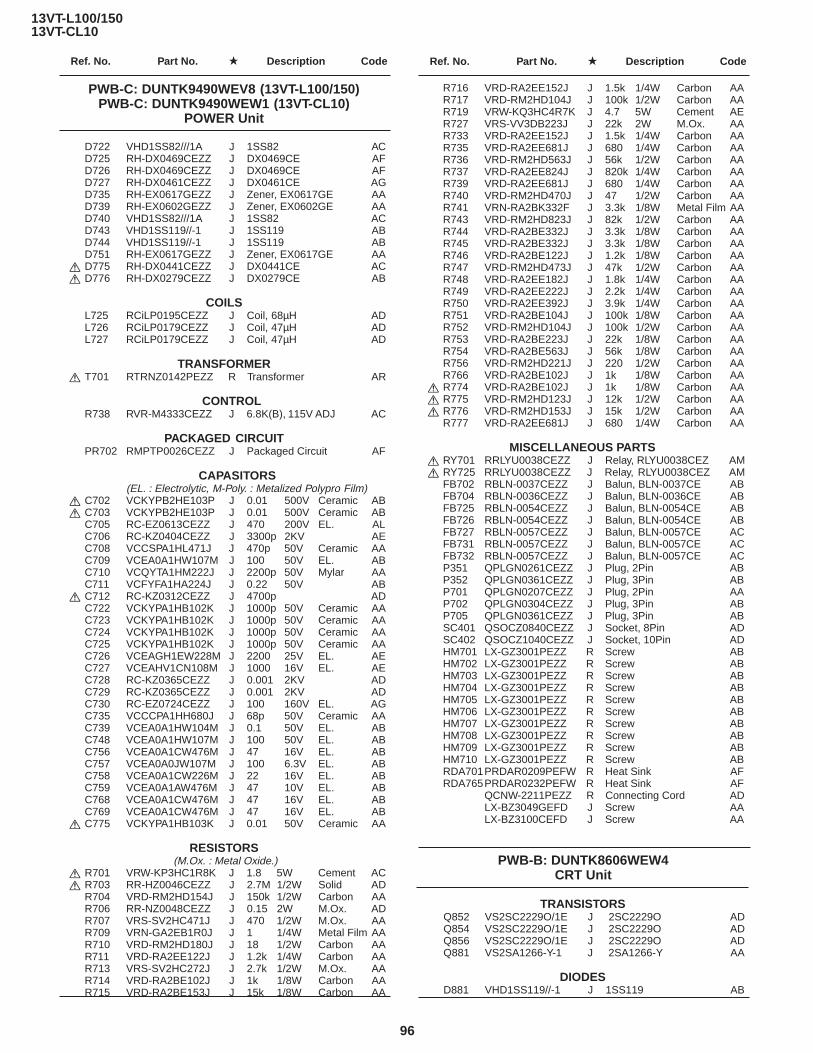
13VT-L100/15013VT-CL10
Ref. No. Part No. ★ Description Code Ref. No. Part No. ★ Description Code
96
PWB-C: DUNTK9490WEV8 (13VT-L100/150)PWB-C: DUNTK9490WEW1 (13VT-CL10)
POWER Unit
D722 VHD1SS82///1A J 1SS82 ACD725 RH-DX0469CEZZ J DX0469CE AFD726 RH-DX0469CEZZ J DX0469CE AFD727 RH-DX0461CEZZ J DX0461CE AGD735 RH-EX0617GEZZ J Zener, EX0617GE AAD739 RH-EX0602GEZZ J Zener, EX0602GE AAD740 VHD1SS82///1A J 1SS82 ACD743 VHD1SS119//-1 J 1SS119 ABD744 VHD1SS119//-1 J 1SS119 ABD751 RH-EX0617GEZZ J Zener, EX0617GE AA
å D775 RH-DX0441CEZZ J DX0441CE ACå D776 RH-DX0279CEZZ J DX0279CE AB
COILSL725 RCiLP0195CEZZ J Coil, 68µH ADL726 RCiLP0179CEZZ J Coil, 47µH ADL727 RCiLP0179CEZZ J Coil, 47µH AD
TRANSFORMERå T701 RTRNZ0142PEZZ R Transformer AR
CONTROLR738 RVR-M4333CEZZ J 6.8K(B), 115V ADJ AC
PACKAGED CIRCUITPR702 RMPTP0026CEZZ J Packaged Circuit AF
CAPASITORS(EL. : Electrolytic, M-Poly. : Metalized Polypro Film)
å C702 VCKYPB2HE103P J 0.01 500V Ceramic ABå C703 VCKYPB2HE103P J 0.01 500V Ceramic AB
C705 RC-EZ0613CEZZ J 470 200V EL. ALC706 RC-KZ0404CEZZ J 3300p 2KV AEC708 VCCSPA1HL471J J 470p 50V Ceramic AAC709 VCEA0A1HW107M J 100 50V EL. ABC710 VCQYTA1HM222J J 2200p 50V Mylar AAC711 VCFYFA1HA224J J 0.22 50V AB
å C712 RC-KZ0312CEZZ J 4700p ADC722 VCKYPA1HB102K J 1000p 50V Ceramic AAC723 VCKYPA1HB102K J 1000p 50V Ceramic AAC724 VCKYPA1HB102K J 1000p 50V Ceramic AAC725 VCKYPA1HB102K J 1000p 50V Ceramic AAC726 VCEAGH1EW228M J 2200 25V EL. AEC727 VCEAHV1CN108M J 1000 16V EL. AEC728 RC-KZ0365CEZZ J 0.001 2KV ADC729 RC-KZ0365CEZZ J 0.001 2KV ADC730 RC-EZ0724CEZZ J 100 160V EL. AGC735 VCCCPA1HH680J J 68p 50V Ceramic AAC739 VCEA0A1HW104M J 0.1 50V EL. ABC748 VCEA0A1HW107M J 100 50V EL. ABC756 VCEA0A1CW476M J 47 16V EL. ABC757 VCEA0A0JW107M J 100 6.3V EL. ABC758 VCEA0A1CW226M J 22 16V EL. ABC759 VCEA0A1AW476M J 47 10V EL. ABC768 VCEA0A1CW476M J 47 16V EL. ABC769 VCEA0A1CW476M J 47 16V EL. AB
å C775 VCKYPA1HB103K J 0.01 50V Ceramic AA
RESISTORS (M.Ox. : Metal Oxide.)
å R701 VRW-KP3HC1R8K J 1.8 5W Cement ACå R703 RR-HZ0046CEZZ J 2.7M 1/2W Solid AD
R704 VRD-RM2HD154J J 150k 1/2W Carbon AAR706 RR-NZ0048CEZZ J 0.15 2W M.Ox. ADR707 VRS-SV2HC471J J 470 1/2W M.Ox. AAR709 VRN-GA2EB1R0J J 1 1/4W Metal Film AAR710 VRD-RM2HD180J J 18 1/2W Carbon AAR711 VRD-RA2EE122J J 1.2k 1/4W Carbon AAR713 VRS-SV2HC272J J 2.7k 1/2W M.Ox. AAR714 VRD-RA2BE102J J 1k 1/8W Carbon AAR715 VRD-RA2BE153J J 15k 1/8W Carbon AA
R716 VRD-RA2EE152J J 1.5k 1/4W Carbon AAR717 VRD-RM2HD104J J 100k 1/2W Carbon AAR719 VRW-KQ3HC4R7K J 4.7 5W Cement AER727 VRS-VV3DB223J J 22k 2W M.Ox. AAR733 VRD-RA2EE152J J 1.5k 1/4W Carbon AAR735 VRD-RA2EE681J J 680 1/4W Carbon AAR736 VRD-RM2HD563J J 56k 1/2W Carbon AAR737 VRD-RA2EE824J J 820k 1/4W Carbon AAR739 VRD-RA2EE681J J 680 1/4W Carbon AAR740 VRD-RM2HD470J J 47 1/2W Carbon AAR741 VRN-RA2BK332F J 3.3k 1/8W Metal Film AAR743 VRD-RM2HD823J J 82k 1/2W Carbon AAR744 VRD-RA2BE332J J 3.3k 1/8W Carbon AAR745 VRD-RA2BE332J J 3.3k 1/8W Carbon AAR746 VRD-RA2BE122J J 1.2k 1/8W Carbon AAR747 VRD-RM2HD473J J 47k 1/2W Carbon AAR748 VRD-RA2EE182J J 1.8k 1/4W Carbon AAR749 VRD-RA2EE222J J 2.2k 1/4W Carbon AAR750 VRD-RA2EE392J J 3.9k 1/4W Carbon AAR751 VRD-RA2BE104J J 100k 1/8W Carbon AAR752 VRD-RM2HD104J J 100k 1/2W Carbon AAR753 VRD-RA2BE223J J 22k 1/8W Carbon AAR754 VRD-RA2BE563J J 56k 1/8W Carbon AAR756 VRD-RM2HD221J J 220 1/2W Carbon AAR766 VRD-RA2BE102J J 1k 1/8W Carbon AA
å R774 VRD-RA2BE102J J 1k 1/8W Carbon AAå R775 VRD-RM2HD123J J 12k 1/2W Carbon AAå R776 VRD-RM2HD153J J 15k 1/2W Carbon AA
R777 VRD-RA2EE681J J 680 1/4W Carbon AA
MISCELLANEOUS PARTSå RY701 RRLYU0038CEZZ J Relay, RLYU0038CEZ AMå RY725 RRLYU0038CEZZ J Relay, RLYU0038CEZ AM
FB702 RBLN-0037CEZZ J Balun, BLN-0037CE ABFB704 RBLN-0036CEZZ J Balun, BLN-0036CE ABFB725 RBLN-0054CEZZ J Balun, BLN-0054CE ABFB726 RBLN-0054CEZZ J Balun, BLN-0054CE ABFB727 RBLN-0057CEZZ J Balun, BLN-0057CE ACFB731 RBLN-0057CEZZ J Balun, BLN-0057CE ACFB732 RBLN-0057CEZZ J Balun, BLN-0057CE ACP351 QPLGN0261CEZZ J Plug, 2Pin ABP352 QPLGN0361CEZZ J Plug, 3Pin ABP701 QPLGN0207CEZZ J Plug, 2Pin AAP702 QPLGN0304CEZZ J Plug, 3Pin ABP705 QPLGN0361CEZZ J Plug, 3Pin ABSC401 QSOCZ0840CEZZ J Socket, 8Pin ADSC402 QSOCZ1040CEZZ J Socket, 10Pin ADHM701 LX-GZ3001PEZZ R Screw ABHM702 LX-GZ3001PEZZ R Screw ABHM703 LX-GZ3001PEZZ R Screw ABHM704 LX-GZ3001PEZZ R Screw ABHM705 LX-GZ3001PEZZ R Screw ABHM706 LX-GZ3001PEZZ R Screw ABHM707 LX-GZ3001PEZZ R Screw ABHM708 LX-GZ3001PEZZ R Screw ABHM709 LX-GZ3001PEZZ R Screw ABHM710 LX-GZ3001PEZZ R Screw ABRDA701PRDAR0209PEFW R Heat Sink AFRDA765PRDAR0232PEFW R Heat Sink AF
QCNW-2211PEZZ R Connecting Cord ADLX-BZ3049GEFD J Screw AALX-BZ3100CEFD J Screw AA
PWB-B: DUNTK8606WEW4CRT Unit
TRANSISTORSQ852 VS2SC2229O/1E J 2SC2229O ADQ854 VS2SC2229O/1E J 2SC2229O ADQ856 VS2SC2229O/1E J 2SC2229O ADQ881 VS2SA1266-Y-1 J 2SA1266-Y AA
DIODESD881 VHD1SS119//-1 J 1SS119 AB

13VT-L100/15013VT-CL10
Ref. No. Part No. ★ Description Code Ref. No. Part No. ★ Description Code
97
D882 VHD1SS119//-1 J 1SS119 ABD885 VHD1SS119//-1 J 1SS119 AB
CAPACITORS (EL. : Electrolytic)
C851 VCCCPA1HH151J J 150p 50V Ceramic AAC852 VCCCPA1HH151J J 150p 50V Ceramic AAC853 VCCCPA1HH151J J 150p 50V Ceramic AAC854 RC-KZ0016CEZZ J 0.01 1.4KV ACC881 VCEA0A1HW106M J 10 50V EL. ABC883 VCEA0A1CW336M J 33 16V EL. AB
RESISTORS (M.Ox. : Metal Oxide.)
R851 VRD-RA2BE470J J 47 1/8W Carbon AAR852 VRD-RA2BE331J J 330 1/8W Carbon AAR853 VRD-RA2BE121J J 120 1/8W Carbon AA
å R857 VRS-VV3AB123J J 12k 1W M.Ox. AAR858 VRD-RM2HD332J J 3.3k 1/2W Carbon AAR859 VRD-RA2BE470J J 47 1/8W Carbon AAR860 VRD-RA2BE331J J 330 1/8W Carbon AAR861 VRD-RA2BE121J J 120 1/8W Carbon AA
å R865 VRS-VV3AB123J J 12k 1W M.Ox. AAR866 VRD-RM2HD332J J 3.3k 1/2W Carbon AAR867 VRD-RA2BE470J J 47 1/8W Carbon AAR868 VRD-RA2BE331J J 330 1/8W Carbon AAR869 VRD-RA2BE121J J 120 1/8W Carbon AA
å R873 VRS-VV3AB123J J 12k 1W M.Ox. AAR874 VRD-RM2HD332J J 3.3k 1/2W Carbon AAR881 VRD-RA2BE102J J 1k 1/8W Carbon AAR882 VRD-RA2BE221J J 220 1/8W Carbon AAR883 VRD-RA2BE561J J 560 1/8W Carbon AAR884 VRD-RA2BE152J J 1.5k 1/8W Carbon AA
MISCELLANEOUS PARTSP851 QPLGN0561CEZZ J Plug, 5Pin ABP852 QPLGN0461CEZZ J Plug, 4Pin ABSC851 QSOCV0842CEZZ J Socket, 8Pin AH
QCNW-5025PEN4 R Connecting Cord, 4Pin AEQCNW-5030PEN5 R Connecting Cord, 5Pin AE
PWB-B: DUNTK8606WEW4CRT Unit
27 MSLiP0010AJZZ V Sifter AH29 MSPRD0175AJFJ V Reverse Guide Spring 2 AE30 MSPRT0402AJFJ V Loading Double Action AE
Spring31 MSPRT0403AJFJ V Pinch Double Action AD
Spring32 MSPRC0213AJFJ V Earth Spring AC33 MSPRT0416AJFJ V Tension Spring AD34 NBLTK0067AJ00 V Reel Belt AE35 NDAiV1078AJ00 V Reel Disk AE36 NGERH1293AJZZ V Loading Connect Gear AD37 NGERH1295AJ00 V Master Cam AE38 NGERH1294AJZZ V Casecon Drive Gear AD39 NGERH1270AJZZ V Take-Up Loading Gear AF40 NGERH1271AJZZ V Supply Loading Gear AD41 NGERH1272AJZZ V Pinch Drive Cam AE43 NGERH1299AJZZ V Reel Relay Gear AE44 NGERW1070AJZZ V Worm Gear AD45 NGERW1066AJZZ V Worm Wheel Gear AD46 NiDR-0018AJZZ V Idler Wheel Ass’y AK47 NPLYV0162AJZZ V Motor Pully AD48 NPLYV0163AJZZ V Limitter Pulley Ass’y AM49 NROLP0131GEZZ J Guide Roller AL50 NSFTP0032AJZZ V Tension Pole Adjuster AB51 MSPRC0217AJFJ V Guide Roller Spring AC52 PREFL1011AJZZ V Light Guide AE53 QCNW-0247AJZZ V FFC for Drum Motor AG55 QCNW-0272AJZZ V FFC for A/C Head AF56 QPWBF5469AJZZ V A/C Head PWB AE57 QSOCN0605REN1 V Socket, 6 pin AB58 RHEDT0036AJZZ V Full Erase Head AM59 RHEDU0088GEZZ J A/C Head Ass’y AV60 RMOTM1078GEZZ J Loading Motor AK61 RMOTN2055GEZZ J Capstan Motor BA62 RMOTP1135GEZZ J Drum Drive Motor AX63 DDRMW0028TEX1 V Upper and lower BP
drum Ass’y65 QBRSK0041GEZZ J Drum Earth Brush AD66 XBPSD26P05J00 V Drum Drive Motor AA
Mounting Screw(SW2.6P+5S)
67 PGiDC0056GEFW J Drum Base AL68 QPWBF5468AJZZ V PWB(LDG Motor) AE69 QPLGZ0292GEZZ J Socket(LDG Motor) AE70 MSPRC0223AJFJ V Azimuth Spring AC71 MSPRC0224AJFJ V Height Adjusting spring AC
MECHANISM CHASSIS
1 LBNDK1011AJZZ V Tension Band Ass’y AH2 LBOSZ1007AJZZ V Tension Arm boss AD4 LBOSZ1006AJZZ V Cassette Stay L AD5 LCHSM0166AJZZ V Main Chassis Ass’y BA6 LHLDZ2016AJZZ V Loading Motor Block AG7 LPOLM0063GEZZ J Supply Pole Base Ass’y AM8 LPOLM0064GEZZ J Take-Up Pole Base Ass’y AM9 MLEVF0518AJZZ V Take-Up Loading AF
Arm Ass’y10 MLEVF0519AJZZ V Supply Loading AF
Arm Ass’y11 MLEVF0499AJZZ V Pinch Drive Lever Ass’y AG12 MLEVF0500GEZZ J Pinch Roller Lever Ass’y AW15 MLEVF0523AJZZ V Tension Arm Ass’y AH16 LANGF9620AJFW V A/C Head Plate AG17 MLEVP0271AJZZ V Sifter Drive Lever AE18 MLEVP0272AJZZ V Pinch Double Action LeverAD19 MLEVP0301AJZZ V Reverse Guide Lever Ass’yAL20 MLEVP0275AJZZ V Reverse Drive Lever AD21 MLEVP0292AJZZ V Slow Brake Lever AE22 MLEVP0290AJZZ V Open Lever AD23 MLEVP0293AJZZ V Clutch Lever AE24 MLEVP0294AJZZ V Sup Main Brake Ass’y AF25 MLEVP0295AJZZ V Take-Up Main Brake AF
Ass’y26 CLEVP0287AJZZ V Auto Head Cleaner Ass’y AG
SCREW, NUTS AND WASHERS
201 XBPSD26P08000 V Screw 2.6P+8S A/C Head AA202 LX-HZ3082GEZZ J A/C Head Screw AD203 XHPSD26P06000 V Screw, C2.6P+6S AA
(For Capstan Motor)207 XHPSD30P08WS0 V Screw, C3.0P+8S AA
(For Drum Base)208 XRESJ30-06000 V E-Ring, E-3 AA209 XWHJZ31-05052 V Washer, W3.1-5.2-0.5 AC210 XWHJZ31-03052 V Washer, W3.1-5.2-0.3 AC211 XWHJZ31-04052 V Washer, W3.1-5.2-0.4 AC212 XWHJZ31-06052 V Washer, W3.1-5.2-0.6 AC213 XWHJZ31-07052 V Washer, W3.1-5.2-0.7 AC214 PSPAP0009AJZZ V Reverse Guide AB
Adjusting Nut216 LX-WZ1041GE00 J CW 2.5-6-0.5 CAM AA218 XBPSD30P08J00 V Drum Base Mounting AA
Screw (SW 3P+8S)219 LX-WZ1098GE00 J CW 2.6-4.7-10.5 RED AB220 LX-BZ3096GEFD J Tilt Adjusting Screw AA221 XBPSD26P06000 V Azimuth Adjusting Screw AA
2.6+6S222 LX-BZ3197GEFD J Screw (A/C Head) AD223 XWHJZ31-08052 V Washer, W3.1-5.2-0.8 AC224 LX-RZ3015GEFJ J CS Washer AB
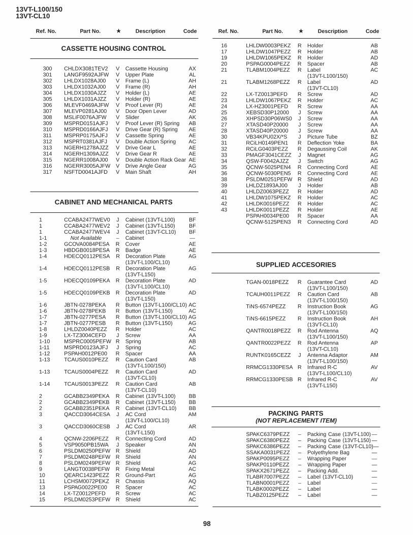
13VT-L100/15013VT-CL10
Ref. No. Part No. ★ Description Code Ref. No. Part No. ★ Description Code
98
CASSETTE HOUSING CONTROL
300 CHLDX3081TEV2 V Cassette Housing AX301 LANGF9592AJFW V Upper Plate AL302 LHLDX1028AJ00 V Frame (L) AH303 LHLDX1032AJ00 V Frame (R) AH304 LHLDX1030AJZZ V Holder (L) AE305 LHLDX1031AJZZ V Holder (R) AE306 MLEVF0469AJFW V Proof Lever (R) AE307 MLEVP0281AJ00 V Door Open Lever AD308 MSLiF0076AJFW V Slider AK309 MSPRD0151AJFJ V Proof Lever (R) Spring AB310 MSPRD0166AJFJ V Drive Gear (R) Spring AE311 MSPRP0175AJFJ V Cassette Spring AE312 MSPRT0381AJFJ V Double Action Spring AC313 NGERH1278AJZZ V Drive Gear L AE314 NGERH1309AJZZ V Drive Gear R AE315 NGERR1008AJ00 V Double Action Rack Gear AE316 NGERR3005AJFW V Drive Angle Gear AG317 NSFTD0041AJFD V Main Shaft AH
CABINET AND MECHANICAL PARTS
1 CCABA2477WEV0 J Cabinet (13VT-L100) BF1 CCABA2477WEV2 J Cabinet (13VT-L150) BF1 CCABA2477WEV4 J Cabinet (13VT-CL10) BF1-1 Not Available – Cabinet —1-2 GCOVA0084PESA R Cover AE1-3 HBDGB0018PESA R Badge AE1-4 HDECQ0112PESA R Decoration Plate AG
(13VT-L100/CL10)1-4 HDECQ0112PESB R Decoration Plate AG
(13VT-L150)1-5 HDECQ0109PEKA R Decoration Plate AD
(13VT-L100/CL10)1-5 HDECQ0109PEKB R Decoration Plate AD
(13VT-L150)1-6 JBTN-0278PEKA R Button (13VT-L100/CL10) AC1-6 JBTN-0278PEKB R Button (13VT-L150) AC1-7 JBTN-0277PESA R Button (13VT-L100/CL10) AG1-7 JBTN-0277PESB R Button (13VT-L150) AG1-8 LHLDZ0040PEZZ R Holder AC1-9 LX-TZ3004CEFD J Screw AA1-10 MSPRC0005PEFW R Spring AB1-11 MSPRD0123AJFJ J Spring AC1-12 PSPAH0012PE00 R Spacer AA1-13 TCAUS0010PEZZ R Caution Card AB
(13VT-L100/150)1-13 TCAUS0004PEZZ R Caution Card AD
(13VT-CL10)1-14 TCAUS0013PEZZ R Caution Card AB
(13VT-CL10)2 GCABB2349PEKA R Cabinet (13VT-L100) BB2 GCABB2349PEKB R Cabinet (13VT-L150) BB2 GCABB2351PEKA R Cabinet (13VT-CL10) BB3 QACCD3064CESA J AC Cord AM
(13VT-L100/CL10)3 QACCD3060CESB J AC Cord AR
(13VT-L150)4 QCNW-2206PEZZ R Connecting Cord AD5 VSP9050PB15WA J Speaker AN6 PSLDM0250PEFW R Shield AD7 PSLDM0248PEFW R Shield AN8 PSLDM0249PEFW R Shield AG9 LANGT0038PEFW R Fixing Metal AC10 QEARC1423PEZZ R Ground-Part AG11 LCHSM0072PEKZ R Chassis AQ13 PSPAG0022PE00 R Spacer AC14 LX-TZ0012PEFD R Screw AC15 PSLDM0253PEFW R Shield AC
16 LHLDW0003PEKZ R Holder AB17 LHLDW1047PEZZ R Holder AB19 LHLDW1065PEKZ R Holder AD20 PSPAG0004PEZZ R Spacer AB21 TLABM1004PEZZ R Label AC
(13VT-L100/150)21 TLABM1268PEZZ R Label AD
(13VT-CL10)22 LX-TZ0013PEFD R Screw AD23 LHLDW1067PEKZ R Holder AC24 LX-HZ3001PEFD R Screw AA25 XEBSD30P12000 J Screw AA26 XHPSD30P06WS0 J Screw AA27 XTASD40P20000 J Screw AA28 XTASD40P20000 J Screw AA30 VB34KPU02X/*S J Picture Tube BZ31 RCiLH0149PEN1 R Deflection Yoke BA32 RCiLG0403PEZZ R Degaussing Coil AK33 PMAGF3041CEZZ J Magnet AG34 QSW-F0042AJZZ J Switch AG35 QCNW-5025PEN4 R Connecting Cord AE36 QCNW-5030PEN5 R Connecting Cord AE38 PSLDM0251PEFW R Shield AD39 LHLDZ1893AJ00 J Holder AB40 LHLDZ0063PEZZ R Holder AD41 LHLDW1075PEKZ R Holder AC42 LHLDK0016PEZZ R Holder AC43 LHLDK0011PEZZ R Holder AE
PSPAH0034PE00 R Spacer AAQCNW-5125PEN3 R Connecting Cord AD
SUPPLIED ACCESORIES
TGAN-0018PEZZ R Guarantee Card AD(13VT-L100/150)
TCAUH0011PEZZ R Caution Card AB(13VT-L100/150)
TiNS-6574PEZZ R Instruction Book AG(13VT-L100/150)
TiNS-6615PEZZ R Instruction Book AH(13VT-CL10)
QANTR0018PEZZ R Rod Antenna AQ(13VT-L100/150)
QANTR0022PEZZ R Rod Antenna AP(13VT-CL10)
RUNTK0165CEZZ J Antenna Adaptor AM(13VT-L100/150)
RRMCG1330PESA R Infrared R-C AV(13VT-L100/CL10)
RRMCG1330PESB R Infrared R-C AV(13VT-L150)
PACKING PARTS(NOT REPLACEMENT ITEM)
SPAKC6379PEZZ – Packing Case (13VT-L100) —SPAKC6380PEZZ – Packing Case (13VT-L150) —SPAKC6386PEZZ – Packing Case (13VT-CL10)—SSAKA0031PEZZ – Polyethylene Bag —SPAKP0095PEZZ – Wrapping Paper —SPAKP0110PEZZ – Wrapping Paper —SPAKX2671PEZZ – Packing Add. —TLABR7007PEZZ – Label (13VT-CL10) —TLABN0001PEZZ – Label —TLABK0002PEZZ – Label —TLABZ0125PEZZ – Label —

13VT-L100/15013VT-CL10
Ref. No. Part No. ★ Description Code Ref. No. Part No. ★ Description Code
99
22
31
12
2018
214
19
29
49
51
8
11
203
49
51
7
58
52
4
25
242
33
15
1
50
218
207
67
207
63
62
66
66
6653
65
21641
61
21
38
17
208
6047
44
6
30
36
9
39 224
45
219
10
30
40
27
43
46
43
35
35
37
34
23
62
48
209210211212213223
5
26
32
68
69
224
55
16
202222
221
201
202
202
220
59
70
57
71
56
A
B
C
D
E
F
G
H
I
J
1 2 3 4 5 6 7 8 9 10
MECHANISM CHASSIS PARTS

13VT-L100/15013VT-CL10
Ref. No. Part No. ★ Description Code Ref. No. Part No. ★ Description Code
100
A
B
C
D
E
F
G
H
I
J
1 2 3 4 5 6 7 8 9 10
CABINET AND MECHANICAL PARTS
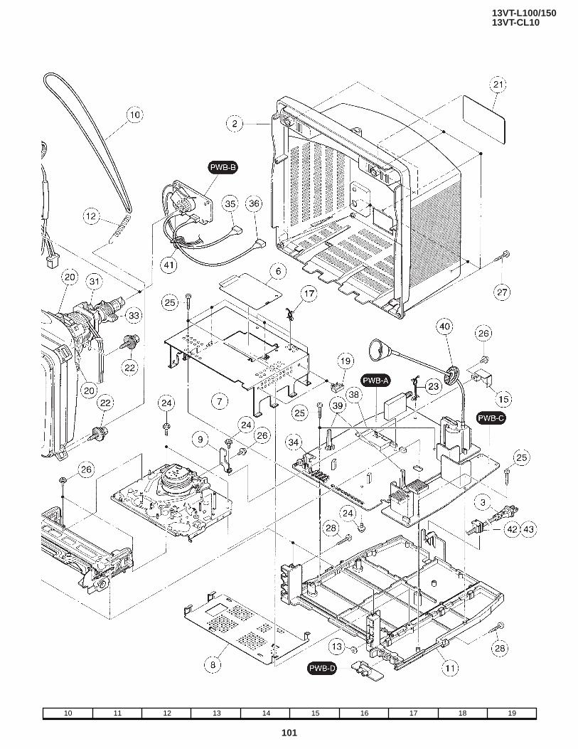
13VT-L100/15013VT-CL10
Ref. No. Part No. ★ Description Code Ref. No. Part No. ★ Description Code
101
10 11 12 13 14 15 16 17 18 19
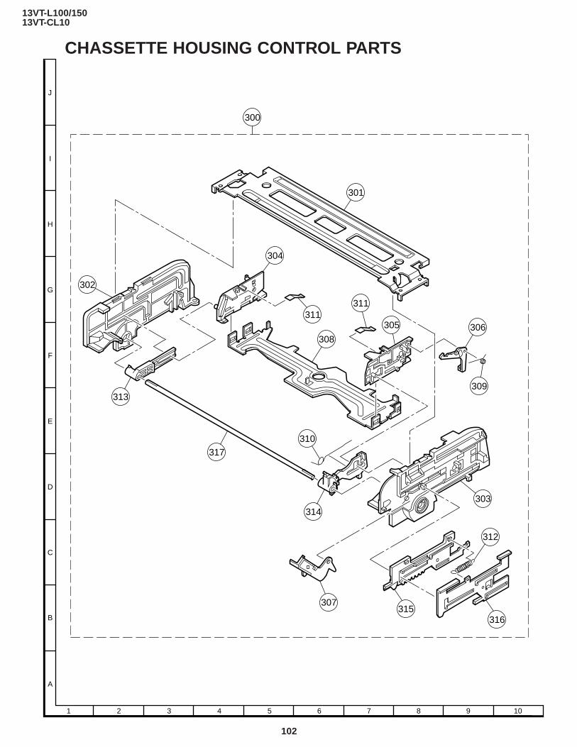
13VT-L100/15013VT-CL10
Ref. No. Part No. ★ Description Code Ref. No. Part No. ★ Description Code
102
A
B
C
D
E
F
G
H
I
J
1 2 3 4 5 6 7 8 9 10
CHASSETTE HOUSING CONTROL PARTS
301
300
304
311
308
311
305 306
309
303
312
316315
307
314
310
317
313
302

13VT-L100/15013VT-CL10
Ref. No. Part No. ★ Description Code Ref. No. Part No. ★ Description Code
103
PACKING OF THE SET • SETTING POSITIONS OF THE KNOBS
Power SW OFF
Use 22 staples to fix the packing
case.
MARK ★ : Not Replacement Items.
FRONT
REAR
★ Buffer Material(Top and Bottom)
★ Polystyrene Bag
Infrared R/C Unit
Operation ManualGuarantee Card★ Batteries
Rod Antenna
★ Polyethylene Sack
★ Packing Case
★ Number Card
★ Serial Number Label
13VT-L100/15013VT-CL10
Ref. No. Part No. ★ Description Code Ref. No. Part No. ★ Description Code
104
SHARP CORPORATIONAV Systems GroupQuality & Reliability Control CenterYaita, Tochigi 329-2193, Japan
COPYRIGHT C 1999 BY SHARP CORPORATION
ALL RIGHTS RESERVED.
No part of this publication may be reproduced,
stored in a retrieval system, or transmitted in
any form or by any means, electronic, mechanical,
photocopying, recording, or otherwise, without
prior written permission of the publisher.
TQ0608-SFeb. 1999 Printed in JAPAN
KI. NS


