1 s2.0-s0376738800824503-main
22
Journal of Membrane Science, 58 (1991) 117-138 Elsevier Science Publishers B.V.. Amsterdam 117 Electrodialysis water splitting technology K.N. Mani Aquatech Systems. Allied-Signal Inc., 7 Powder Horn Drive, Warren, NJO7059-5191 (USA) (Received October 16,1989; accepted in revised form September 13,199O) Abstract Membrane water splitting technology is a general purpose unit operation for converting water soluble salts to their corresponding acids and bases. The process uses bipolar ion exchange mem- branes in conjunction with convertional cation and/or anion exchange membranes and the sep- aration and rearrangement of ions is effected by a direct current driving force. The absence of electrochemical transformations enables the water splitting process to be energy efficient, as well as permits direct processing of oxidation sensitive chemicals and fluoride salts. The technology has many applications in the areas of pollution control/resource recovery and chemical processing. This paper provides a general background on the process itself, some techo-economic considera- tions in design, as well as a review of some of the major applications. Keywords: bipolar membranes; electrodialysis; ion exchange membranes; electrochemistry; acid/ base production Introduction Aqueous salt streams, e.g. NaCl, Na,SO, are generated in many diverse chemical processing operations such as flue gas scrubbing, metals pickling, fermentation and rayon manufacture. Conventional techniques such as recov- ery via evaporative crystallization or disposal in waterways are proving to be increasingly expensive because of the high cost of capital and the stringent environmental regulations. Disposal of these salts also represents a lost re- source since the processor usually has to replace it with purchased acids and bases. Electrodialytic water splitting is an energy efficient means for converting the salts to their acids and bases [l-4]. The technology, which is presently being commercialized by the Aquatech Systems division of Allied-Signal Inc., is based on the successful development of a unique low resistance/high per- formance bipolar ion exchange membrane. At present the first commercial 0376-7388/91/$03.50 0 1991- Elsevier Science Publishers B.V.
-
Upload
rehan-khatri -
Category
Business
-
view
58 -
download
0
Transcript of 1 s2.0-s0376738800824503-main
Journal of Membrane Science, 58 (1991) 117-138 Elsevier Science Publishers B.V.. Amsterdam
117
Electrodialysis water splitting technology
K.N. Mani
Aquatech Systems. Allied-Signal Inc., 7 Powder Horn Drive, Warren, NJO7059-5191 (USA)
(Received October 16,1989; accepted in revised form September 13,199O)
Abstract
Membrane water splitting technology is a general purpose unit operation for converting water soluble salts to their corresponding acids and bases. The process uses bipolar ion exchange mem- branes in conjunction with convertional cation and/or anion exchange membranes and the sep- aration and rearrangement of ions is effected by a direct current driving force. The absence of electrochemical transformations enables the water splitting process to be energy efficient, as well as permits direct processing of oxidation sensitive chemicals and fluoride salts. The technology has many applications in the areas of pollution control/resource recovery and chemical processing. This paper provides a general background on the process itself, some techo-economic considera- tions in design, as well as a review of some of the major applications.
Keywords: bipolar membranes; electrodialysis; ion exchange membranes; electrochemistry; acid/ base production
Introduction
Aqueous salt streams, e.g. NaCl, Na,SO, are generated in many diverse chemical processing operations such as flue gas scrubbing, metals pickling, fermentation and rayon manufacture. Conventional techniques such as recov- ery via evaporative crystallization or disposal in waterways are proving to be increasingly expensive because of the high cost of capital and the stringent environmental regulations. Disposal of these salts also represents a lost re- source since the processor usually has to replace it with purchased acids and bases.
Electrodialytic water splitting is an energy efficient means for converting the salts to their acids and bases [l-4]. The technology, which is presently being commercialized by the Aquatech Systems division of Allied-Signal Inc., is based on the successful development of a unique low resistance/high per- formance bipolar ion exchange membrane. At present the first commercial
0376-7388/91/$03.50 0 1991- Elsevier Science Publishers B.V.

118
plant that uses this technology is operational [ 51. In this paper we will provide background on the technology, some technical and economic considerations useful in devising and optimizing chemical processes and a review of the major applications.
Technical background
The technology uses ion exchange membranes to concentrate the ions in solution and is driven by an electrical potential and in this respect is closely related to electrodialytic concentration. A drawing of the generalized three- compartment water splitting cell is shown in Fig. 1. The three chambers, acid, salt and base, are bounded by the bipolar, anion and cation membranes as shown. In a commercial operation, up to 200 such cell units are assembled between a single set of electrodes to form a compact water splitting stack in which feed to the acid, base and salt chambers is achieved via internal mani- folds. The salt, e.g. sodium sulfate, is fed to the chamber between the cation and anion selective membranes. When an electrical potential is applied across the electrodes, the cations (Na+ ) and anions (SO:- ) move across the mono- polar membranes and combine with the hydroxide and hydrogen ions gener- ated at the bipolar membrane to form the base and acid. The generation of new products distinguishes electrodialytic water splitting from conventional electrodialysis.
The heart of the water splitter is the bipolar membrane. An expanded view of its construction and operation is shown in Fig. 2. The membrane is a com- posite one and consists of three parts, a cation selective region, an anion selec- tive region and the interface between the two regions. When a direct current is passed across the bipolar membrane with the cation selective side toward the cathode, electrical conduction is achieved by the transport of H+ and OH-
Standard Mode HX SOLN L I- Depleted MX SOLN
d OH-f9 “‘$$;H* b
Hill 1 ,rg 2 2 SOLN
Legend
0 Bipolar Membrane
0 Cation Membrane
0 Anion Membrane
Fig. 1. Three compartment cell.
119
t H+ Cathode
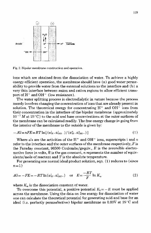
Fig. 2. Bipolar membrane construction and operation.
ions which are obtained from the dissociation of water. To achieve a highly energy efficient operation, the membrane should have (a) good water perme- ability to provide water from the external solutions to the interface and (b) a very thin interface between anion and cation regions to allow efficient trans- port of H+ and OH- (low resistance).
The water splitting process is electrodialytic in nature because the process merely involves changing the concentration of ions that are already present in solution. The theoretical energy for concentrating H+ and OH- ions from their concentration in the interface of the bipolar membrane (approximately 10e7 A4 at 25’ C) to the acid and base concentrations at the outer surfaces of the membrane can be calculated readily. The free energy change in going from the interior of the membrane to the outside is given by:
-dG=nFE=RTln[ (a~+a~u_)/(a&+~~~-)] (1)
Where u’s are the activities of the H+ and OH- ions, superscripts i and o refer to the interface and the outer surfaces of the membrane respectively, F is the Faraday constant, 96500 Coulombs/gequiv., E is the reversible electro- motive force in volts, R is the gas constant, n represents the number of equiv- alents/mole of reactant and 2’ is the absolute temperature.
For generating one normal ideal product solution, eqn. (1) reduces to (since n=l)
dG= -FE= -RTln(u~+uou_) or E=- -RTlnK F w
(2)
where K, is the dissociation constant of water. To overcome this potential, a positive potential E. = -E must be applied
across the membrane. Using the data on free energy for dissociation of water one can calculate the theoretical potential for generating acid and base for an ideal (i.e. perfectly permselective) bipolar membrane as 0.83V at 25°C and

120
0.874V at 70°C. The theoretical energy requirement can be computed to be under 560 kWh/MT (MT = metric ton) of NaOH.
Figures 3 and 4 show the actual potential drop behavior of a bipolar mem- brane made by Aquatech Systems. As seen in Fig. 3, the membrane shows a steeply rising voltage at low currents followed by a flattening out at the higher current densities as would be expected for transport across low resistance ion exchange membranes. In the commercially interesting range of 50-150 mA/ cm2 the membrane has a potential drop of 0.9-l.lV in a 0.5M Na,SO, solution. In more concentrated solutions the potential drop is slightly higher, as shown in Fig. 4, primarily due to the higher osmotic pressures. When contrasted with the theoretical E, value, the Aquatech bipolars can be seen to be highly energy efficient.
0 20 40 60 80 100
Current Density (mAem’)
Fig. 3. Potential drop across bipolar membrane.
Acid Base - 3 7% Na+O, 7% Na,SO, n Sat. N&l 6.6%&OH a Sat. NaCl 15.6% NaOH
14t I
071 ; I 5 25 50 75 100
Current Density mA,cm’
Fig. 4. Potential drop across bipolar membrane in various media.

121
In addition to energy consumed by the water splitting operation, there are ohmic resistances associated with the transport of ions in the acid, salt and base solutions and through the cation, anion and bipolar membranes. A typical three compartment cell would have a potential drop of 1.6-2.5V at a current density of 100 mA/cm2. Careful attention, therefore, has to be paid toward the selection of monopolar membranes as well as to ensure that the various solu- tion streams have adequate electrical conductivity. The energy requirement is represented by the equation:
Kell =M~Rn + CLl) +&I =LlR, +& (3)
P= 10AldEcell = 1OA (I& +I&,) (4)
Where A is the effective membrane area ( m2 ) , Id is the current density (A/ cm2 ), R, and Rsoln represent the individual resistances of the membranes and solutions ( Q-cm2 ), Ecell represents the unit cell potential (V) and P is the power requirement (kW) .
The membrane area requirement is the second important design parameter because it determines the overall capital investment and contributes to the overall operating cost since the membranes require replacement at the end of their useful life. Effective membrane area A is given by the expression:
JF A=-
lo%&
where J represents gequiv./sec of material processed and q represents overall current (faraday) efficiency, i.e. the number of equivalents of product per far- aday of electrical current input. The latter is an important process parameter that will be discussed further in the next section.
From eqns. (4) and (5) one can see that a doubling of the process current density at constant product rate and current efficiency will result in the mem- brane area being halved but will result in as much as a doubling of power con- sumption. There is also potential for reduced membrane life at the higher cur- rent densities (i.e. higher operating cost). In any process optimization one therefore has to weigh the advantages of reduced capital investment (lower membrane area) against the increased energy and maintenance costs.
Another important factor that must be considered is the heat generation, which is directly related to the power consumption. The water splitting process operates at significantly higher current densities and voltage drops than con- ventional electrodialysis and, therefore, generates a greater amount of heat. Not all the electrical energy used by the water splitter is converted to heat, since work is done to concentrate the H+ and OH- ions, in addition to the minor potential drops associated with other concentration differences. As a first approximation, the heat generated, Q (kcal/hr ) can be written as:
Q=f360LAU3,,1,--&) (6)

122
Process design considerations
Based on our extensive studies on converting various salts to acids and bases, a generalized set of guidelines for successful operation of the Aquatech cells has been developed. These guidelines are designed to ensure that the water splitter can operate for long periods of time in an economical and cost efficient manner. This section covers the general guidelines, experimental setup op- tions, as well as the cell transport characteristics. Operating techniques and cell configurations that can be used to improve water splitter performance or for devising novel applications are detailed in the following section.
Table 1 summarizes the general process requirements for the Aquatech tech- nology. The guideline are designed to ensure that the overall process has a current efficiency of 80% or higher at a current density of 100 mA/cm’. At this performance level the Aquatech cell can generate a metric ton of sodium hy- droxide using 1400-2000 kWh of DC power.
It should be pointed out that the criteria outlined in Table 1 apply to the boundary of the cell stack only. If the feed characteristics and/or product spec- ifications are outside the boundary, one has to use suitable pre/posttreatment to enable the streams to be handled via the water splitting technology. In cer- tain applications where the salt stream contains metals such as Fe, Cr, Ni a
TABLE 7
General process guidelines
Feed salt soln: Soluble salts
Clear solution
Conductivity > 35000 ,&/cm
Metal contaminants (Ca, Mg, Fe etc.) < 2 ppm (relaxable for weak base
generation)
Acid product:
Minimize high MW organics
Caution with acids having poor solubility at lower pH
Typical product concentration:
Strong acids = 1N
Sulfate/sulfuric z 2N
Weak acids= 3-6N
Base product:
General:
S02, CO,, H,S > 95 wt.%
Typical product strength:
NaOH, KOH, Na&O,, K&O,, NaySO, Y 3-6N
Temperature: ambient-50°C
Non-oxidizing chemicals
Current density: 50-150 mA/cm’
Unit cell voltage: 1.3-1.9V (2 compt)
1.6-2.5V (3 compt)
Expected membrane life: 1 yr. +

123
simple pH adjustment followed by careful filtration can make the stream ready for processing through the Aquatech cell. Often, however, the presence of mul- tivalent impurities (Ca, Mg, etc.) would necessitate further purification via ion exchange. Chelating resins such as Amberlite IRC-718 or Duolite C467 are quite effective in reducing the contaminant metal levels to < lppm. The key consideration in establishing the guidelines shown in Table 1 is to minimize the formation of insoluble impurities inside the cell stack and to avoid fouling of the membrane by multivalent cationic and high molecular weight anionic material. Proper and adequate pretreatment is critical for the long term stable operation of the water splitter.
In arriving at a suitable design/configuration of the water splitter cell for a given application careful consideration should be given to the following: 9 overall current efficiency l product purity and strength l water balance around the process
The three items are interrelated but for a given application any one of them can become the prime factor for reasons of market demand or overall economics.
Current efficiency The current (faraday) efficiency is an important process parameter in elec-
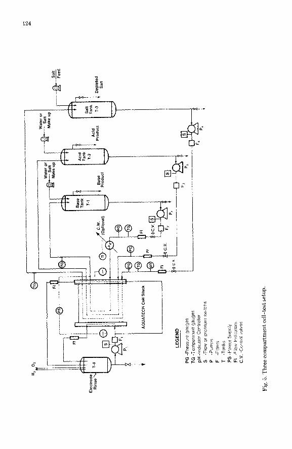
trodialytic processes. A typical experimental set up for measuring the perform- ance of a three-compartment cell is shown in Fig. 5. The experimental tech- niques are similar to those used in conventional electrodialysis. Feed to the acid, base, salt and electrode rinse loops is achieved with recirculation tanks and pumps. Make up of process solutions and withdrawal of product is easily achieved from the recirculation tanks. It is also possible to replace the tanks with small pipe sections so that the overall hold up in the loops is minimized. The electrode rinse stream is typically l-2Nbase (NaOH, KOH) and requires only infrequent changes. Use of a basic electrode rinse allows the water splitter cell to operate with a nickel anode and a 316SS cathode. Typical linear solution velocity in the stacks is 5-8 cm/set. The experiment set up should preferably have on-line guard filters (5-10 pm), flow meters and diaphragm valves to monitor and regulate flow and flow-pressure switches to permit unattended operation. The entire assembly should be plumbed with plastic materials, pref- erably PVC but PP is acceptable. Membrane performance is monitored through voltage drop and current efficiency measurements on a periodic basis.
Generally speaking the performance of the water splitter is controlled by the permselectivities of the individual component membranes and by diffusive transport. This is illustrated in Fig. 6 which shows the various processes that contribute to the overall current efficiency. Line 1 represents the desirable process that produces, in the net, acid and base from salt and water. Competing with this are the unwanted processes, all of which reduce the current efficiency. out ofLine 2 represents the inefficiency arising from the imperfect permselec-
AQ
UA
TEC
H
Cel
l S
tack
LEG
EN
D
PG
-P
ress
ure
gaug
es
TG
-T
empe
ratu
re
gaug
es
pH
-In
&c
ato
r C
On
trO
iler
S -F
low
or
pr
essu
re
swltc
hs
P
-Pum
ps
F
-Filt
ers
T -T
aoks
PS
-P
ower
Su
pp
ly
FI
-Flo
w
Ind
ica
tors
C.V
. -C
ontr
ol
valv
es
Dep
lete
d S
alt
Fig
. 5.
Th
ree
com
part
men
t ce
ll-t
est
setu
p.
125
+ -+
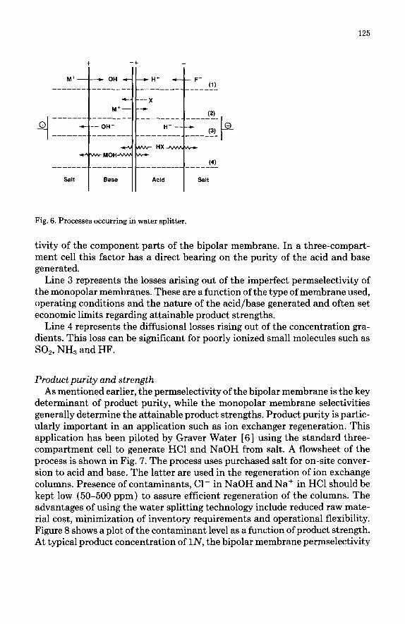
Fig. 6. Processes occurring in water splitter.
tivity of the component parts of the bipolar membrane. In a three-compart- ment cell this factor has a direct bearing on the purity of the acid and base generated.
Line 3 represents the losses arising out of the imperfect permselectivity of the monopolar membranes. These are a function of the type of membrane used, operating conditions and the nature of the acid/base generated and often set economic limits regarding attainable product strengths.
Line 4 represents the diffusional losses rising out of the concentration gra- dients. This loss can be significant for poorly ionized small molecules such as SO2, NH, and HF.
Product purity and strength As mentioned earlier, the permselectivity of the bipolar membrane is the key
determinant of product purity, while the monopolar membrane selectivities generally determine the attainable product strengths. Product purity is partic- ularly important in an application such as ion exchanger regeneration. This application has been piloted by Graver Water [ 61 using the standard three- compartment cell to generate HCl and NaOH from salt. A flowsheet of the process is shown in Fig. 7. The process uses purchased salt for on-site conver- sion to acid and base. The latter are used in the regeneration of ion exchange columns. Presence of contaminants, Cl- in NaOH and Na+ in HCl should be kept low (50-500 ppm) to assure efficient regeneration of the columns. The advantages of using the water splitting technology include reduced raw mate- rial cost, minimization of inventory requirements and operational flexibility. Figure 8 shows a plot of the contaminant level as a function of product strength. At typical product concentration of lN, the bipolar membrane permselectivity

126
Fig. 7. Ion exchanger regeneration.
7
6- .
. Na in Acid
\o 5 0 + Cl in Base
; Id = 100 mA/cm’ 4-
E
.E 3 E m s 2-
0
l-
0, I I I 04 06 08 1 12 14 16 18 2 22 :
Concentration of Acid or Base, eq.‘l 4
Fig. 8. Ion exchanger regeneration. Product contamination vs. concentration.
is seen to be 97-98%. Purity levels can be enhanced further by operating at a lower product concentration or by increasing the current density.
In general for strong acids/bases the permselectivity of the anion membrane is lower than that of the cation membrane at a given normality. Consequently when a salt such as NaCl is processed in a three-compartment cell, the salt stream becomes acidic. This acidity is typically a loss in current efficiency. However, in one application involving brine acidification for membrane chlor- alkali or sodium chlorate production, one is able to recover this acid and design a process around it. A flowsheet of this is shown in Fig. 9. Typically a chlorate or chlor-alkali plant requires 4-8% of its chlorine/chlorate production in the form of makeup HCl. The acid is required for acidifying the brine feed as well as for use in ion exchangers and chlorine/chlorate recovery. Using the three- compartment cell one can readily generate three useful product streams namely NaOH, an acidified brine and HCl, all of which can be used in the downstream plant.

127
Cl2 3-S wt% Solid Lime
5-15 wt?& 4 HCI N&l NaOH 3-8 wt% HCI NaOH
HCI
‘I Saturated Addition
Brine 1 , ii
Feed I3
Chlorine ------) Stripper -
uesaturator _ Brine IClIl ---_--
* Purification - Exchange - ’ -
A -’
I I
I 1 1 C3++ 3 Hz C’z
ca++/fdg++
t t Sludge
Depleted Brine *
Chlor-Alkali Acidified Brine pH 3 Membrane Electrotyzer a
. NaOH Product to Evaporator
Fig. 9. Chlor-alkali brine acidification.
TABLE 2
Concentration transport (C,) for acids and bases in the Aquatech cell
Product CT (X0)
HF 18-25 NH, 20-30 NaOH 30-40 KOH 35-45 HCl 50-70 H,SO, 50-90
Water balance consideration Careful consideration to water balance is a key to successful design of pro-
cesses using the water splitting. This is because the water splitter internally generates high concentrations of acid and base. The so-called concentration transport (CT), defined as the ratio of product transport to the total transport (product + water) is significant for many acids and bases. Estimated CT values for a number of acids, bases are shown in Table 2. Permselectivity and eco- nomic considerations generally prohibit operation of the water splitter at such high product concentrations. However, if water (or dilute solution) recycle streams were available, they can be incorporated in an overall design, thereby reducing capital and energy costs for concentrating and processing the dilute streams.
Two examples are used to illustrate this. The first is a process for regener- ating spent stainless steel pickle liquor. This process has been commercialized at Washington Steel, Washington, Pennsylvania, where a plant for processing

128
6 x lo6 l/yr of pickle liquor is presently operational. A flowsheet of the process is shown in Fig. 10. The process uses recycled KOH solution to precipitate the metals values from the pickle liquor. The clear filtrate containing KF and KNO, is processed via the Aquatech cell to generate a mixed acid stream to be sent to the pickling step and a KOH stream for use in the neutralization step.
In this application the mixed acid stream has to be relatively pure. Conse- quently fresh water is used to pick up the acid generated. The KOH stream, however, is simply reused in the neutralization step. Consequently in our pro- cess design, the depleted KF solution from the salt loop is used to collect the base generated. Overall water removal requirements are thereby reduced considerably.
A second example is in the regeneration of sodium sulfate in a rayon plant. In the process (Fig. 11) crystallized Glauber salt is purified and used as the salt feed in a three compartment cell for conversion to NaOH and H&30,. Water is used to generate a clean NaOH solution for reuse in the cellulose dissolution step, while the spent spin bath liquor containing 15-20 wt.% Na,SO, 6-8 wt.% H&SO, is circulated through the acid loop to collect the acid gener- ated. The spin bath liquor is thereby “fortified” with the high strength H&SO, transported (CT = 50-90% H2S04). 0 Vera11 water removal requirements are thereby reduced dramatically, while the current efficiencies are maintained at a high level (Fig. 12).
r
Fig. 10. Pickle liquor recovery process.

129
I 27.9% Na,SO,
Evaporator
12.3% H,SO, +
28% Na,SO, Spent Bath
7.65% H-SO. Liquor
10.8% H,SOa
25.6% Na,SO,
Acid J Salt +
------ r 20% NaOH 16.8% H,SO, Base
SOI’ll 8.8% N&SO, AQUATECH Cell
.
Fig. 11. Rayon process flowsheet.
0 0 Aquatech Anion Membrane
A lonics’ UZL Membrane 1.0, I
Wt% H,SO,
Fig. 12. Effect of sulfuric concentration on efficiency.
Optimization of water splitter performance
For a given salt conversion application, an optimum design involves deci- sions on cell configuration, membrane selection and operating modes/tech-

130
niques. The items listed in Table 1 can be used as broad guidelines in the initial phase of the process design. Experimentation with the actual feed stream is often necessary to identify potential problems regarding membrane perform- ance and stability (especially fouling) as well as to identify potential process integration problems.
Cell arrangements The discussion in the previous section was focused on the standard three-
compartment cell. This is a general purpose unit that can operate over a wide range of salt concentrations and generate relatively pure, concentrated acid and base. However, in certain applications other cell arrangements may be more appropriate. These include:
(a) Two compartment cation cell This arrangement is shown in Fig. 13a and consists of a bipolar membrane
operating in conjunction with a cation membrane. This arrangement is appro- priate for converting salts of weak acids (e.g. Na salts of organic acids) into a mixed acid/salt stream and a relatively pure base stream. It is particularly advantageous when the salt stream is a concentrated solution, e.g. 2-5N. This is because in this arrangement, in addition to the transport processes outlined in Fig. 6, one has to deal with the competing transport of ions of like charges. As can be seen in Fig. 13a, both M+ and H+ ions can be transported across the cation membrane. Only the transport of M+ ions results in the formation of useful products. In this instance the process efficiency is determined primarily by the relative mobilities and concentrations of the two species in the acid loop.
(b) Two compartment anion cell This arrangement is shown in Fig. 13b and consists of a bipolar membrane
and an anion membrane. This type of cell can be used for converting salts of weak bases (e.g. NH,NO,) to a salt/base mixture and a relatively pure acid product. The cell can also be used for salts of strong bases (e.g. Na and K salts) but in such cases the final base concentration in the salt loop must be relatively low, e.g. O.l-0.2lv, to minimize the competitive transport of OH- ion with the X- ion.
(c) Multichamber cation cell This cell is shown in Fig. 13c and consists of two cation membranes in con-
junction with a bipolar membrane. Salt solution is first fed to the chamber between the two cation membranes and the product from this loop is then circulated through the acid compartment. The net result is a salt/acid stream with a higher concentration of acid than a standard two-compartment cation cell. Alternately the cell can be used to generate the same salt/acid composition

131
HX + MX MOH MOH
t
H+ OH- _ --* - H’
M+
t Salt/Acid Base
t ’ I MX H;O
(a)
,,+ _~
t
-
J HX + MX
HX MOH + MX HX
H;O MX
W
tvl+
SaWAcid
I
MX
w
OH-
M+
Base
f
H,O
MX
W
MOH + MX
Fig. 13. Alternate cell arrangements.
at a higher current efficiency. The product base from the cell is essentially the same as that from the two compartment cation cell.
(d) Multichamber anion cell This arrangement shown in Fig. 13d is composed of two anion membranes
in conjunction with a bipolar membrane. This cell can be used to enhance the performance of the two compartment anion cell in a manner analogous to that used for the multichamber cation cell.
Membrane selection The performance of the water splitter cell is obviously very much dependent
on the performance of the individual membranes comprising it. From Figs. 3, 4, 8 and 14 one can see that the Aquatech bipolar membrane itself is highly energy efficient and has high permselectivity in applications of commercial interest.

0.6
t
ld = 109 mA/cm’
11 1 N N&SO, on Acid side
(R,‘s measured in OSM Na,So, Sol’n)
04
t
0.2 0 H’ Generation of Aquatech Biopolar Membrane
q l,A NaOH Production with Aquatech Cation Membrane
02 8 10 12 14 16
wt% NaOH
Fig. 14. Two compartment cation cell. Performance of Aquatech bipolar and cation membranes in NaOH generation.
Aquatech Systems has also developed an efficient cation membrane [ 71 that is suitable for use in non-oxidizing applications for generating bases of l-4N strength. Typical performance of this membrane for the NaOH application is shown in Fig. 14. This membrane is a suitable complement to the bipolar mem- brane in most applications. Commercially available Nafion@ or similar per- fluorinated membranes can be used instead of the Aquatech cation mem- branes, particularly in applications where the oxidative degradation is of concern. The perfluorinated membranes are particularly suited for use in ends of the water splitter stack next to the electrodes where the presence of oxygen can cause stability problems for non-perfluorinated membranes. A potentially lower cost option for the electrode ends is the Ionac MC-4375 cation mem- branes which is mechanically strong and is claimed to be resistant to oxidation. Commercially available non-fluorinated cation membrane from Asahi Glass and Tokuyama Soda can be used in a number of water splitting applications.
Selection of an anion membrane for a given application is the most difficult because there are only limited choices available. All of the commercially avail- able anion membranes have permselectivity and/or stability problems that prohibit their use or restrict the strength of the acid product. Only a few of the commercial anion membranes have been found to be suitable for use in the

133
water splitters. These are RAI-4035 (RAI Corporation), AAV and AMP (from Asahi Glass) and to a limited extent Ionics UZL and QZL series.
Cell operating modes A number of operational techniques can be used to enhance the performance
of the water splitter in a given application. The important ones are:
(a) Product batching As noted earlier, the permselectivities of the membranes decrease as the
product concentration increases. Consequently a process operating in a steady state, feed and bleed mode and generating the products at the highest concen- trations is also working at the lowest current efficiency. This effect is even more pronounced in a two-compartment cell where competition between ions of like charges tends to affect performance more severely. Product batching allows the water splitter to operate at lower average concentrations, and there- fore at a higher overall current efficiency. The effect of product batching is illustrated in Fig. 15 for a two-compartment cation cell using a sodium sulfate feed. It can be seen that at 100% conversion of sulfate to bisulfate, product batching yields an efficiency of over 70% while the feed and bleed method has a current efficiency of only 38%.
Conversion of ~20 wt% Na,SO, to Na,SO, + H,SO,
Id = 100 mA/cm*
Multichamber
7-
r (Two Compartment)
.4-
3 (Two Compartment)
I1 I I I ! I I I I 0 .l 2 .3 .4 .5 6 7 8 .9 .lO
Conversion At 50°C
Conversion = 2 x moles of H2S01
moles of H,SO, + moles of Na,SO,
Fig. 15. Sodium sulfate conversion. Two compartment or multichamber cation cells.

134
(b) Multichamber cell operation Efficiency of a two-compartment cell is improved through use of a third
compartment “to capture” the H+ (or OH- ) ions that have transported across the monopolar membrane and return them to the product loop. This is shown graphically in Fig. 14 for a cell containing two cation membranes for conver- sion of sodium sulfate. It can be seen that even though the cell is being operated in a steady state mode it has a higher current efficiency of 78% at 100% con- version. The two cation membrane cell is, however, somewhat more complex than the conventional two-compartment cell and would operate at a slightly higher voltage drop.
(c) Product removal/stripping When the application involves relatively volatile species such as ammonia
or sulfur dioxide, process efficiency can be increased significantly by continu- ously removing the product via thermal or vacuum stripping. The technique has the added benefit in that the recovered product is at a high concentration, making it easily storable/saleable.
An important example incorporating this concept is in the fermentation field. A number of organic and amino acids are produced efficiently by this technique but usually at low concentrations, e.g. 0.2-1N. The fermentation process typ- ically operates at a near neutral pH; this being maintained via addition of a suitable base. Increasing the product concentration significantly reduces the productivity of the fermentor due to product inhibition.
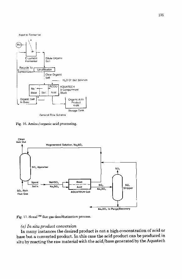
Membrane water splitting technology provides an ideal complement to the fermentation technology by removing the product acid, while simultaneously providing an equivalent amount of base for use in adjusting the pH in the fermentor. The fermentor itself can now be operated at relatively low product concentrations to assure high productivity. As an added advantage the re- covered acid is usually at a significantly higher concentration (e.g. 4-6N) so that the subsequent purification via crystallization or other techniques is rel- atively inexpensive. Figure 16 shows a typical flowsheet of the combined process.
(d) Use of a supporting electrolyte As mentioned earlier, in a two compartment cation cell, for example, the
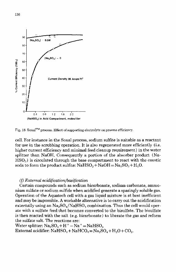
process efficiency is influenced by competitive transport of H+ and M+. Use of a supporting electrolyte raises concentration of M+ ions so that the overall efficiency is improved significantly. An excellent example is in our Soxal flue gas desulfurization process [ 81 where the presence of sodium sulfate as a sup- porting electrolyte enhances the water splitter efficiency dramatically. Figure 17 shows a drawing of the Soxal process for regenerating the spent bisulfite. Figure 18 shows the impact of the supporting electrolyte in raising the overall process efficiency.
135
Feed to Fermenter
Dilute Organic Salt
Fig. 16. Amino/organic acid processing.
ClC?tWl Gas Out
Regenerated Solution, Na,S03
SO, Absorber
spent __--__
S0l’n SO* SO2
Na,SO, Stripper SO2 Rich
Flue Gas ABUATECki Cell
4 Na,SO, to Purge/Recovery
Fig. 17. Soxal TM flue gas desulfurization process.
(e) In situ product conversion In many instances the desired product is not a high concentration of acid or
base but a converted product. In this case the acid product can be produced in situ by reacting the raw material with the acid/base generated by the Aquatech
136
0 90-R 0 0
[Na,SO,l = 0.5M
80-
70-
-? 8 60.
z
2 5 50-
‘G E w 40. Current Density 86 AmpsiFt’ E 2 5 30-
I
”
$ zo- :
I
I 0.4 0.6 1.2 1.6 20
(NaHSO,) In Acid Compartment, moles/liter
Fig. 18. SoxalTM process. Effect of supporting electrolyte on process efficiency.
cell. For instance in the Soxal process, sodium sulfite is suitable as a reactant for use in the scrubbing operation. It is also regenerated more efficiently (i.e. higher current efficiency and minimal feed cleanup requirement) in the water splitter than NaOH. Consequently a portion of the absorber product (Na- HSO,) is circulated through the base compartment to react with the caustic soda to form the product sulfite: NaHSO, + NaOH = Na,S0,3 + H,O.
(f) External acidification/basification Certain compounds such as sodium bicarbonate, sodium carbonate, ammo-
nium sulfate or sodium sulfide when acidified generate a sparingly soluble gas. Operation of the Aquatech cell with a gas liquid mixture is at best inefficient and may be impossible. A workable alternative is to carry out the acidification externally using an Na,SO,/NaHSO, combination. Thus the cell would oper- ate with a sulfate feed that becomes converted to the bisulfate. The bisulfate is then reacted with the salt (e.g. bicarbonate) to liberate the gas and reform the sulfate salt. The reactions are: Water splitter: Na,SO, + H+ - Na+ = NaHSO, External acidifier: NaHSO, + NaHCO, = Na,SO, + H,O + COz.

137
(g) External precipitation This technique is another version of external acidification. A number of or-
ganic acid salts, when acidified, result in the precipitation of the acid. Since the Aquatech cell requires the use of clear solution, an option here would be to acidify the salt externally, say with the bisulfate, to precipitate the acid exter- nal to the cell. The bisulfate is concurrently converted to sulfate which can now be processed in the water splitter.
Discussion and conclusion
The water splitting technology provides a method for recovering spent salts and reformulating them to their original acids and bases and as such is a gen- eral purpose unit operation. In this paper we have attempted to give a general background on the water splitting technology, and, using practical examples,
TABLE 3
Technology applications pollution control/resource recovery
l HF/Mixed acid recovery
l Sulfate recovery
- Stainless steel pickle liquor recovery - HF/NaOH recovery from spent aluminium potlinings - Fluosilicic acid conversion to HF, SiOp - Fluoride emission control in chemical processing
l Pulp & Paper
- Battery acid recovery - Waste sodium sulfate conversion - Sodium sulfate conversion in rayon manufacture
- Sodium alkali recycling in pulping & bleaching operations
l Flue gas desulfurization - SoxalTM process SO, recovery - Dry sodium scrubbing-alkali recovery
Chemical processing l Organic acid production/recovery
- Acetic, formic, citric and amino acids *Ion exchanger regeneration *Brine acidification in chlor-alkali industry l Potassium and sodium mineral processing
- KC1 conversion - Solution mining of trona and subsequent sodium alkali
production - Sodium alkali production from natural brines & solid
trona . Ilmenite (FeO.FTiO,) upgrading with coproduction of KOH
- Upgrading to synthetic rutile - Fluoride route to TiOz pigment

138
covered the many cell configurations and operating techniques that can be used to devise new processes or improve existing ones. In addition to the pro- cesses illustrated in the previous sections, there are applications in fluoride recovery, minerals processing, pulping chemical recovery, etc. Table 3 shows a partial list of the applications that have been identified and/or developed by Aquatech Systems. The applications have been classified under the broad cat- egories of pollution control/resource recovery and chemical processing. New applications for the technology are continually being uncovered. Our economic studies show that in many applications involving salt splitting, Aquatech tech- nology is superior to the conventional options that are presently available. Technologists and researchers should, therefore, give serious consideration to using this technology in applications involving process improvements or re- source recovery/recycling.
References
1 K. Nagasubramanian, F.P. Chlanda and K.J. Liu, Use of bipolar membranes for generation of
acid and base - An engineering and economic analysis, J. Membrane Sci., 2 (2 1 (1977) 109.
2 K.N. Mani, F.P. Chlanda and C.H. Byszewski, AQUATECH membrane technology for recov-
ery of acid/base values from salt streams, Desalination, 68 (1988) 149-166. 3 K.J. Liu, F.P. Chlanda and K. Nagasubramanian, Application of bipolar membrane technol-
ogy: A novel process for control of sulfur dioxide from Flue gases, J. Membrane Sci., 3( 1)
(1978) 57.
4 K.J. Liu, K. Nagasubramanian and F.P. Chlanda, Membrane electrodialysis process for recov-
ery of sulfur dioxide from power plant stack gases, J. Membrane Sci., 3 (1) (1978) 71.
5 C.H. Byszewski and A.S. Bogeatzes, AQUATECH systems - A commercial process for recy-
cling spent pickle liquor, Iron Steel Eng., March (1988) 40-44.
6 T.A. Davis and A. Laterra, Onsite generation of acid and base with bipolar membranes, Paper presented at the 48th Annual Meeting, International Water Conference, Pittsburgh, Pennsyl-
vania, Nov. 1987.
7 Y.C. Chiao, R.S. Cooke and F.P. Chlanda, Cation membranes for water splitting applications,
Paper presentedat AIChE Summer National Meeting, Denver, Colorado, Aug., 1988; Also U.S.
Patent 4,738,764 to Allied-Signal Inc.
8 K.N. Mani and F.P. Chlanda, “SoxalTM process, results of laboratory and pilot studies, Paper
presented at 2nd Annual Pittsburgh Coal Conference, Pittsburgh, Pennsylvania, Sept. 1985.